EP2243923B1 - Sicherheitsvorrichtung für Notfallunterbrechung der Bohrmanöver - Google Patents
Sicherheitsvorrichtung für Notfallunterbrechung der Bohrmanöver Download PDFInfo
- Publication number
- EP2243923B1 EP2243923B1 EP10153562.3A EP10153562A EP2243923B1 EP 2243923 B1 EP2243923 B1 EP 2243923B1 EP 10153562 A EP10153562 A EP 10153562A EP 2243923 B1 EP2243923 B1 EP 2243923B1
- Authority
- EP
- European Patent Office
- Prior art keywords
- door
- arm
- microswitch
- drilling
- mast
- Prior art date
- Legal status (The legal status is an assumption and is not a legal conclusion. Google has not performed a legal analysis and makes no representation as to the accuracy of the status listed.)
- Not-in-force
Links
- 238000005553 drilling Methods 0.000 title claims description 32
- 230000004913 activation Effects 0.000 claims description 7
- 238000013016 damping Methods 0.000 claims description 4
- 230000004397 blinking Effects 0.000 claims description 3
- 230000007935 neutral effect Effects 0.000 claims description 3
- 230000009467 reduction Effects 0.000 claims description 3
- 238000009434 installation Methods 0.000 description 5
- 238000003780 insertion Methods 0.000 description 4
- 230000037431 insertion Effects 0.000 description 4
- 238000000034 method Methods 0.000 description 4
- 230000009471 action Effects 0.000 description 3
- 238000004904 shortening Methods 0.000 description 3
- 230000008901 benefit Effects 0.000 description 2
- 230000008878 coupling Effects 0.000 description 2
- 238000010168 coupling process Methods 0.000 description 2
- 238000005859 coupling reaction Methods 0.000 description 2
- 238000011161 development Methods 0.000 description 2
- 230000000694 effects Effects 0.000 description 2
- 238000005516 engineering process Methods 0.000 description 2
- 238000012423 maintenance Methods 0.000 description 2
- 230000007257 malfunction Effects 0.000 description 2
- 239000000463 material Substances 0.000 description 2
- 239000012190 activator Substances 0.000 description 1
- 230000004888 barrier function Effects 0.000 description 1
- 238000005266 casting Methods 0.000 description 1
- 235000019994 cava Nutrition 0.000 description 1
- 238000007596 consolidation process Methods 0.000 description 1
- 230000008030 elimination Effects 0.000 description 1
- 238000003379 elimination reaction Methods 0.000 description 1
- 239000002360 explosive Substances 0.000 description 1
- 238000002156 mixing Methods 0.000 description 1
- 239000000203 mixture Substances 0.000 description 1
- 238000009527 percussion Methods 0.000 description 1
- 239000004033 plastic Substances 0.000 description 1
- 238000009418 renovation Methods 0.000 description 1
- 230000003252 repetitive effect Effects 0.000 description 1
- 230000009466 transformation Effects 0.000 description 1
Images


Classifications
-
- E—FIXED CONSTRUCTIONS
- E21—EARTH OR ROCK DRILLING; MINING
- E21B—EARTH OR ROCK DRILLING; OBTAINING OIL, GAS, WATER, SOLUBLE OR MELTABLE MATERIALS OR A SLURRY OF MINERALS FROM WELLS
- E21B41/00—Equipment or details not covered by groups E21B15/00 - E21B40/00
- E21B41/0021—Safety devices, e.g. for preventing small objects from falling into the borehole
Definitions
- the field of the present invention is related to the drilling machines which functioning in many technological fields, can require from the auxiliary services personnel manual interventions in zones exposed to dangers.
- all the drilling machines require interventions from the personnel generally subdividable into: first mounting interventions, maintenance interventions and manual interventions contemporary to the working maneuvers.
- the installation care personnel is generally prepared for dealing with this kind of issues and the attention threshold of the personnel is high because the work is each time different and never repetitive.
- the base installations of transformation for making the machine suitable for a specific technology are specific and different case by case.
- the maintenance interventions can be required after scheduled operations of specific actions caused by unpredicted issues. Even in this case the experience of the intervention personnel, the specificity of the issues and the usual practice bring to consider this step as not particularly dangerous.
- the risk exposure is very high because the operations are of routine type (and this physiologically creates an attention reduction in people who does repetitively the same action), with parts in speedy movement and timetable to reduce to the maximum for increasing the productivity.
- the mast in proximity of the mast, it is to be located a device for the emergency interruption, which rapidly and safely interrupts the main drilling maneuvers: the rule requires the instantaneous interruption of the rotation and of the moving forward and backward of the driving head, given to the rods by the driving head.
- devices for the emergency interruption In order to prevent an effective or potential danger, devices for the emergency interruption must be supplied. They must interrupt the most rapidly possible any dangerous movement, for avoiding the development of a dangerous situation without, however, creating additional dangers. In each operating or piloting station there must be an emergency device. A device for the emergency interruption with local effect must interrupt a specific and limited function, such as rotation and moving forward.
- the devices for the emergency interruption must be placed in positions easily reachable by the operator.
- the emergency interruption after the operation, must remain active until it is manually rearmed. This manual rearm must not start the machine, but shall only enable the reboot via the normal procedure. More in particular for the safety devices in proximity of the mast, the rule prescribes:
- the drilling machines with a forward movement guide if there is the danger for the personnel for being caught up and injured by the rotating element, must be provided with additional sensitive devices, in the immediate surroundings of the system of rods of the rotating driller, accessible by the personnel.
- the sensitive devices must be installed and equipped in such a way as to be automatically started in emergency situation by the body, or parts of the body, without any delay or difficulty.
- the actuators of the sensitive device must be clearly marked. If the drilling machine is equipped with a system for tube or drilling rod handling, it is sufficient a sensitive device on the free side of the tube or of the drilling rod. When the sensitive device is started, any energy residual in the system must be contained or dissipated in such a way as to not cause dangerous movements.
- the sensitive device after the operation, must remain active until the manual rearm. This manual rearm must not start the machine but shall only enable the reboot via normal procedure. If such a sensitive device cannot be realized because of operating modes, the dangerous zone must be a forbidden entry zone during the drilling and during the carrying out of other dangerous operations. The forbidden entry area must be indicated by the sign "Off limits”.
- the first device which regularly finds application in almost all of the drilling machines in which is required the manual intervention for the mounting of rods, is the so-called “emergency rope” or “emergency cable”.
- This device is characterized by a lower arm which has a coupling upon which is bolted a tensioning element of the cable, which has at its opposed end, a coupler for the rope (generally in plastic material and red colored for being clearly marked and evident).
- a positive controlled double-contact microswitch On the opposite end of the rope, it is connected a positive controlled double-contact microswitch, which is pre-tensioned with a pre-charging stroke manually given to the tensioner.
- a positive controlled double-contact microswitch In case of emergency or danger, the operator in proximity of the mast can pull in any direction the rope. This movement causes the extension of the piston of the micro, which after a very short stroke (from 3 to 5mm) releases the contact and the dangerous maneuvers are immediately interrupted.
- the rearm is then carried out in proximity of the sensitive device itself, by counter-rotating a button (generally red) provided for this rearm maneuver. Obviously, the micro must therefore find itself to eye level, for being safely and easily rearmed.
- the negative aspects of this solution are such that it is considered as non-safe.
- the main aspects are all connected to the ease with which the micro carries out its stroke and releases the interruption of the maneuvers.
- the presence of vibrations (completely normal in movement or during the drilling) or of scarce tensioning of the system (the same rope caves in and relaxes during the time or it is subject to extensions owing to the exposure to thermal gaps) always produce a continuous inserting of the micro which, by repetitively interrupting the maneuvers, makes it impossible to maneuver the machine and work with continuity.
- Another constructive embodiment in alternative to the preceding one, provides for the use of emergency buttons positioned on arms or support doors on the sides of the mast.
- This solution is used when the drilling machine has a very small size and its use is provided for inner works, in the renovation of buildings or in the carrying out and consolidation of tunnels having a reduced transversal section.
- the sensitive devices must be installed in such a way as to be automatically started in emergency situation by the body, or parts of the body, without any delay or difficulty.
- the standard emergency buttons have a reduced diameter and, in case of emergency, are to be searched for in a very precise point of the space around the mast.
- a final known embodiment relates to a sensitive device constituted by an operating plate that is hinged on a side.
- the pressure exerted on the plate which acts in contrast with elastic devices, causes the insertion of a micro contained inside a containing covering.
- the structure appears therefore as a flat box, within which there are the micro and the elastic elements and on the front part a movable cap for the pressure and the activation of the signal.
- the activation plates even big, are limited to a restricted zone and prevent with their shape from safely carrying out the charging of the rods.
- the box with the movable cap is not sealable and being in proximity of the hole, is subject to castings of drain materials, concrete mixings which fill the inner parts by causing general malfunctions and requesting frequent reset activities.
- CA 2 395 962 A1 shows a prior art guard system having doors covered with a metallic net, the doors being closed during operations for safety reasons. Therefore, in combination with these systems, it is required the mounting of sensitive devices, generally emergency ropes, positioned inside the guard, for interrupting the drilling maneuvers.
- Purpose of the invention is to overcome the preceding limits and to solve all the highlighted issues by realizing a strong sensitive and always functioning device, compatible with the stresses caused by the heaviest works and adjustable in position.
- the invention proposes to realize a safety device for emergency interruption of the drilling maneuvers according to the appended claims.
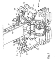
- FIG. 1-6 is shown the base of a drilling machine 10 (it is represented only the lower part of the drilling tower) to which are applied the safety devices object of the invention.
- the arms or doors 11 can rotate around the axis Y pushed or pulled by a manual force exerted on one of the points along the development of the tubulars themselves of the shackle.
- Damping elements 19 are tight against the end of each arm or door 11 by means of a plate 20 adjustable by means of screw means 21 for obtaining an opportune and ideal damping of the vibrations on the arm.
- Each frame 12 laterally brings a covering 23' containing a controlled double contact microswitch 23 (of commonly known type and therefore not described in further details), connected by means of a mechanic rod adjustable in length 24 and on the buttonhole 25 which connects the end of the activation piston of the micro to the rotating bar 11.
- a covering 23' containing a controlled double contact microswitch 23 (of commonly known type and therefore not described in further details)
- a mechanic rod adjustable in length 24 which connects the end of the activation piston of the micro to the rotating bar 11.
- the rod 24 serves for conveniently pre-tensioning the piston of the microswitch 23 by arranging it in median position of its stroke, corresponding to the neutral condition.
- a predefined extra-stroke in extension or in shortening with respect to the neutral condition of start (pre-tensioned) brings the piston to vary the contact and consequently to activate the action of the microswitch 23.
- each arm or door 11 around the axis Y causes an extension or shortening of the piston of the microswitch 23, proportional to the width of the angular movement of rotation of the arm or of the door itself.
- the frames 12 are supported by the mast by couplings of various shape (16, 15) suitable for keeping fixed the frame in a number of multiple positions, more or less near to the drilling axis, for ensuring a suitable protection of the most dangerous zone.
- the microswitch 23 will be connected to command activator means of parts of the machine, such as for example the ones which carry out the rotation and the moving forward of the drilling rods, determining their immediate disengagement with the consequent interruption of the rotation and of the moving forward or backward of the rod, that is to say of the main functional parts of the machine.
- command activator means of parts of the machine such as for example the ones which carry out the rotation and the moving forward of the drilling rods, determining their immediate disengagement with the consequent interruption of the rotation and of the moving forward or backward of the rod, that is to say of the main functional parts of the machine.
- it is possible to command the disengagement of other functions potentially dangerous all referable to the drilling maneuvers (movements of vices, charger, auxiliary pumps, percussions, and so on).
- the return to the center of the arm or of the arms 11 is automatic because it is ensured by rubber pads 19 which crushed by the movement of the arm, elastically push the same to return in balanced position.
- the rubber pads 19 are two and opposed with respect to the tubular arm 11.
- the arms or doors 11 are of guard type, (form of embodiment shown in figures 4 and 5 ), therefore provided with metallic protection net as impediment for entering the dangerous zone, in proximity of the rotation axis Y' of the supporting frame 12 on one of the brackets 15 integral with the mast 17, is inserted a second microswitch 30 (see Figs. 8 and 9 ) activated by the pressure of a piston 31 which, due to the rotation of the corresponding frame 12 of the guard, around the axis Y', is pushed by a cam 32 integral with the frame itself 12.
- the intervention of the microswitch 30 will cause the intervention of, for example, the so-called decalibration mode, that is the reduction of the maneuvering speed and the turn-on of signalization blinking lamps and/or warning buzzers.
Landscapes
- Life Sciences & Earth Sciences (AREA)
- Engineering & Computer Science (AREA)
- Geology (AREA)
- Mining & Mineral Resources (AREA)
- Physics & Mathematics (AREA)
- Environmental & Geological Engineering (AREA)
- Fluid Mechanics (AREA)
- General Life Sciences & Earth Sciences (AREA)
- Geochemistry & Mineralogy (AREA)
- Earth Drilling (AREA)
Claims (9)
- Sicherheitsvorrichtung für die Notunterbrechung des Bohrmanövrierens in einer Bohrmaschine, die mit einem Mast (17) und einer Vorrichtung (10) zum Durchführen des Eintreibens von Bohrelementen in den Boden versehen ist;
aufweisend wenigstens einen Rahmen (12), der an dem Mast (17) befestigt ist und mit wenigstens einem Arm oder einer Tür (11) versehen ist, wobei der Arm oder die Tür in ein Metallnetz gehüllt sind und sich um eine erste Achse (Y) in Bezug auf den Rahmen drehen; der Rahmen (12) ist wiederum an dem Mast (17) eingehängt aber zeitweilig lösbar und rotiert um eine zweite Achse (Y') in Bezug auf den Masten (17);
weiterhin aufweisend einen Mikroschalter (23), der durch die Drehbewegungen um die erste Achse (Y) aktiviert wird, die dem Arm oder der Tür (11) erteilt werden, um wenigstens einige der gefährlichen Bohrmanöver anzuhalten, wobei an dem Rahmen (12) ein zweiter Mikroschalter (30) angebracht ist, der nach der Drehung des entsprechenden Rahmens (12) um die zweite Achse (Y') das Öffnen des Armes oder der Tür (11) signalisiert. - Vorrichtung nach Anspruch 1, dadurch gekennzeichnet, dass die Rahmen (12) zwei an gegenüberliegenden Seiten des Mastes angebrachte Rahmen sind und dass die Arme oder Türen (11) auch zwei Arme oder Türen sind, von denen jeder mit dem Mikroschalter (23) zum Erfassen der Rotation jedes einzelnen der Arme oder Türen selbst (11) versehen ist.
- Vorrichtung nach Anspruch 1, dadurch gekennzeichnet, dass der Mikroschalter (23) ein positiv gesteuerter Doppelkontakt-Mikroschalter ist, der mit dem Dreharm (11) mittels einer in Längsrichtung verstellbaren mechanischen Stange (24) verbunden ist, der das Ende eines Betätigungskolbens des Mikroschalters mit dem rotierenden Arm oder der rotierenden Tür (11) verbindet.
- Vorrichtung nach Anspruch 3, dadurch gekennzeichnet, dass die Stange (24) und die Achse des zugehörigen Kolbens bezüglich der Rotationsachse (Y) des entsprechenden Arms oder der Tür (11) exzentrisch (E) angeordnet sind.
- Vorrichtung nach Anspruch 1, dadurch gekennzeichnet, dass an dem Rahmen (12) entsprechend der Verbindung des Arms oder der Tür (11) Dämpfungselemente (19) vorgesehen sind, die mittels Schraubenmitteln (21) einstellbar sind, um die Vibrationen zu begrenzen und die in elastischem Kontrast gegen den Arm oder die Tür (11) wirken, um ihn in eine zentrierte neutrale Position zu bewegen.
- Vorrichtung nach Anspruch 1, dadurch gekennzeichnet, dass der Rahmen (12) in Bezug auf den Mast in seiner Position verstellbar ist, um den Abstand des Arms oder der Tür (11) von der Bohrachse zu gewährleisten.
- Vorrichtung nach Anspruch 1, dadurch gekennzeichnet, dass der Arm oder die Tür (11) sich über die gesamte Länge des Mastes erstreckt.
- Vorrichtung nach Anspruch 1, dadurch gekennzeichnet, dass das durch das Öffnen des Arms oder der Tür (11) erfasste Drehmanöver den Mikroschalter (30) aktiviert, der den Dekalibrierungsmodus, der die Verringerung der Manövriergeschwindigkeit ist, und die eventuelle Aktivierung von blinkenden Lampen und / oder ertönenden Summer freigibt, die auf der Bohrmaschine installiert sind.
- Vorrichtung nach Anspruch 1, dadurch gekennzeichnet, dass der Mikroschalter (30) durch Drücken eines Kolbens (31) betätigt wird, der durch einen mit dem Rahmen (12) fest verbundenen Nocken (32) gedrückt wird.
Applications Claiming Priority (1)
| Application Number | Priority Date | Filing Date | Title |
|---|---|---|---|
| ITTO2009A000217A IT1393452B1 (it) | 2009-03-20 | 2009-03-20 | Dispositivo di sicurezza per l'interruzione di emergenza delle manovre di perforazione. |
Publications (2)
| Publication Number | Publication Date |
|---|---|
| EP2243923A1 EP2243923A1 (de) | 2010-10-27 |
| EP2243923B1 true EP2243923B1 (de) | 2018-10-10 |
Family
ID=41202652
Family Applications (1)
| Application Number | Title | Priority Date | Filing Date |
|---|---|---|---|
| EP10153562.3A Not-in-force EP2243923B1 (de) | 2009-03-20 | 2010-02-15 | Sicherheitsvorrichtung für Notfallunterbrechung der Bohrmanöver |
Country Status (5)
| Country | Link |
|---|---|
| US (1) | US8232686B2 (de) |
| EP (1) | EP2243923B1 (de) |
| AU (1) | AU2010200622B2 (de) |
| CA (1) | CA2696992C (de) |
| IT (1) | IT1393452B1 (de) |
Families Citing this family (8)
| Publication number | Priority date | Publication date | Assignee | Title |
|---|---|---|---|---|
| US20160032689A1 (en) * | 2013-03-15 | 2016-02-04 | Longyear Tm, Inc. | Drill rod guard and systems and methods of using same |
| EP2921640A1 (de) * | 2014-03-18 | 2015-09-23 | Sandvik Mining and Construction Oy | Schutzkäfig, Gesteinsbohreinheit, Nivellieranordnung und Verfahren zum Steinbohren |
| EP2952671B1 (de) * | 2014-06-05 | 2017-08-30 | Soilmec S.p.A. | Sicherheitssystem für ausgrabungsausrüstung |
| EP2982829B1 (de) * | 2014-08-06 | 2017-06-28 | Soilmec S.p.A. | Sicherheitssystem zur kontrolle eines gefahrenbereichs einer bohrmaschine |
| CN108361005B (zh) * | 2018-03-15 | 2020-03-27 | 延安大学 | 一种抽油机井口安全保护装置 |
| CN110593901B (zh) * | 2019-09-17 | 2021-03-19 | 国家电网有限公司 | 具备主动防护功能的隧道凿岩安全保护台车 |
| IT202000006463A1 (it) * | 2020-03-27 | 2021-09-27 | Casagrande Spa | Macchina perforatrice |
| CN115434634A (zh) * | 2022-08-23 | 2022-12-06 | 四川昌泰建筑工程有限公司 | 一种体育馆施工用旋挖机及其施工方法 |
Family Cites Families (6)
| Publication number | Priority date | Publication date | Assignee | Title |
|---|---|---|---|---|
| US5360072A (en) * | 1993-04-26 | 1994-11-01 | Lange James E | Drill rig having automatic spindle stop |
| WO1997035145A1 (en) * | 1996-03-19 | 1997-09-25 | Doherty Steven G | Machine safety guard |
| CA2395963A1 (en) * | 2002-09-06 | 2004-03-06 | Normand Donald Denis | Percussive or rotary rock drill guard |
| US7293607B2 (en) * | 2004-07-15 | 2007-11-13 | National-Oilwell, L.P. | Automated system for positioning and supporting the work platform of a mobile workover and well-servicing rig |
| US7325599B2 (en) * | 2005-10-31 | 2008-02-05 | John Barker | Safety shield for rotary drilling rigs |
| US7921758B2 (en) * | 2007-02-09 | 2011-04-12 | Schlumberger Technology Corporation | Impact panels |
-
2009
- 2009-03-20 IT ITTO2009A000217A patent/IT1393452B1/it active
-
2010
- 2010-02-15 EP EP10153562.3A patent/EP2243923B1/de not_active Not-in-force
- 2010-02-19 AU AU2010200622A patent/AU2010200622B2/en not_active Ceased
- 2010-03-09 US US12/720,380 patent/US8232686B2/en not_active Expired - Fee Related
- 2010-03-17 CA CA2696992A patent/CA2696992C/en active Active
Non-Patent Citations (1)
| Title |
|---|
| None * |
Also Published As
| Publication number | Publication date |
|---|---|
| ITTO20090217A1 (it) | 2010-09-21 |
| US8232686B2 (en) | 2012-07-31 |
| IT1393452B1 (it) | 2012-04-20 |
| CA2696992C (en) | 2017-04-04 |
| US20100237714A1 (en) | 2010-09-23 |
| CA2696992A1 (en) | 2010-09-20 |
| EP2243923A1 (de) | 2010-10-27 |
| AU2010200622A1 (en) | 2010-10-07 |
| AU2010200622B2 (en) | 2015-07-16 |
Similar Documents
| Publication | Publication Date | Title |
|---|---|---|
| EP2243923B1 (de) | Sicherheitsvorrichtung für Notfallunterbrechung der Bohrmanöver | |
| EP2773816B1 (de) | Sperranordnung | |
| US20160098910A1 (en) | Safety Device | |
| KR101789909B1 (ko) | 개선된 안전성을 갖는 퀵 커플러 | |
| CN102561399A (zh) | 无线电控井盖装置及实现井盖防盗的方法 | |
| EP2949859B1 (de) | Sicherheitssystem zur steuerung eines gefahrenbereichs eines baggers und bagger damit | |
| KR101499298B1 (ko) | 개선된 안전사고 방지구조를 가진 퀵커플러 | |
| EP2952671B1 (de) | Sicherheitssystem für ausgrabungsausrüstung | |
| NO329635B1 (no) | Heisinstallasjon med et temporaert beskyttelsesrom og fremgangsmate for tilveiebringelse av dette | |
| KR102671185B1 (ko) | 지중 배전선로의 사고 예방시스템 | |
| KR101820405B1 (ko) | 퀵 커플러용 자동안전장치 | |
| KR20230147903A (ko) | 위험 지역으로의 진입 차단 시스템 | |
| EP3532764B1 (de) | Vorrichtung und verfahren zur überwachung eines betriebsbereichs | |
| KR101734763B1 (ko) | 개선된 구조를 가진 중장비용 안전퀵커플러 | |
| KR101721773B1 (ko) | 자동잠금기능을 가진 퀵커플러 시스템 및 그 장치 | |
| KR20100024167A (ko) | 건설장비 작업장치용 파편 비산 방지장치 | |
| KR20160029040A (ko) | 갱폼 인양 안전장치 | |
| KR101766443B1 (ko) | 갱폼 인양 안전 시스템 | |
| CN209384745U (zh) | 一种用于双柱升降停车库的全程保险装置 | |
| KR101425075B1 (ko) | 퀵 체인지 결합방식을 갖는 중장비 어태치먼트 구조체 | |
| WO2018128385A1 (ko) | 퀵 커플러용 안전장치 | |
| LU508020B1 (en) | A kind of automatic identification device for intelligent Internet of Things (IoT) garage | |
| JPH10114971A (ja) | 旋回重機の接触防止装置 | |
| CN205802718U (zh) | 电梯松绳断绳保护装置 | |
| KR102504538B1 (ko) | 펌프카용 하부출입 통제장치 |
Legal Events
| Date | Code | Title | Description |
|---|---|---|---|
| PUAI | Public reference made under article 153(3) epc to a published international application that has entered the european phase |
Free format text: ORIGINAL CODE: 0009012 |
|
| AK | Designated contracting states |
Kind code of ref document: A1 Designated state(s): AT BE BG CH CY CZ DE DK EE ES FI FR GB GR HR HU IE IS IT LI LT LU LV MC MK MT NL NO PL PT RO SE SI SK SM TR |
|
| AX | Request for extension of the european patent |
Extension state: AL BA RS |
|
| 17P | Request for examination filed |
Effective date: 20110419 |
|
| 17Q | First examination report despatched |
Effective date: 20110905 |
|
| GRAP | Despatch of communication of intention to grant a patent |
Free format text: ORIGINAL CODE: EPIDOSNIGR1 |
|
| STAA | Information on the status of an ep patent application or granted ep patent |
Free format text: STATUS: GRANT OF PATENT IS INTENDED |
|
| INTG | Intention to grant announced |
Effective date: 20180619 |
|
| GRAS | Grant fee paid |
Free format text: ORIGINAL CODE: EPIDOSNIGR3 |
|
| GRAA | (expected) grant |
Free format text: ORIGINAL CODE: 0009210 |
|
| STAA | Information on the status of an ep patent application or granted ep patent |
Free format text: STATUS: THE PATENT HAS BEEN GRANTED |
|
| AK | Designated contracting states |
Kind code of ref document: B1 Designated state(s): AT BE BG CH CY CZ DE DK EE ES FI FR GB GR HR HU IE IS IT LI LT LU LV MC MK MT NL NO PL PT RO SE SI SK SM TR |
|
| RAP1 | Party data changed (applicant data changed or rights of an application transferred) |
Owner name: SOILMEC S.P.A. |
|
| REG | Reference to a national code |
Ref country code: GB Ref legal event code: FG4D |
|
| REG | Reference to a national code |
Ref country code: CH Ref legal event code: EP Ref country code: AT Ref legal event code: REF Ref document number: 1051470 Country of ref document: AT Kind code of ref document: T Effective date: 20181015 |
|
| REG | Reference to a national code |
Ref country code: IE Ref legal event code: FG4D |
|
| REG | Reference to a national code |
Ref country code: DE Ref legal event code: R096 Ref document number: 602010054164 Country of ref document: DE |
|
| RAP2 | Party data changed (patent owner data changed or rights of a patent transferred) |
Owner name: SOILMEC S.P.A. |
|
| REG | Reference to a national code |
Ref country code: NL Ref legal event code: MP Effective date: 20181010 |
|
| REG | Reference to a national code |
Ref country code: LT Ref legal event code: MG4D |
|
| REG | Reference to a national code |
Ref country code: AT Ref legal event code: MK05 Ref document number: 1051470 Country of ref document: AT Kind code of ref document: T Effective date: 20181010 |
|
| PG25 | Lapsed in a contracting state [announced via postgrant information from national office to epo] |
Ref country code: NL Free format text: LAPSE BECAUSE OF FAILURE TO SUBMIT A TRANSLATION OF THE DESCRIPTION OR TO PAY THE FEE WITHIN THE PRESCRIBED TIME-LIMIT Effective date: 20181010 |
|
| PG25 | Lapsed in a contracting state [announced via postgrant information from national office to epo] |
Ref country code: ES Free format text: LAPSE BECAUSE OF FAILURE TO SUBMIT A TRANSLATION OF THE DESCRIPTION OR TO PAY THE FEE WITHIN THE PRESCRIBED TIME-LIMIT Effective date: 20181010 Ref country code: AT Free format text: LAPSE BECAUSE OF FAILURE TO SUBMIT A TRANSLATION OF THE DESCRIPTION OR TO PAY THE FEE WITHIN THE PRESCRIBED TIME-LIMIT Effective date: 20181010 Ref country code: LV Free format text: LAPSE BECAUSE OF FAILURE TO SUBMIT A TRANSLATION OF THE DESCRIPTION OR TO PAY THE FEE WITHIN THE PRESCRIBED TIME-LIMIT Effective date: 20181010 Ref country code: IS Free format text: LAPSE BECAUSE OF FAILURE TO SUBMIT A TRANSLATION OF THE DESCRIPTION OR TO PAY THE FEE WITHIN THE PRESCRIBED TIME-LIMIT Effective date: 20190210 Ref country code: FI Free format text: LAPSE BECAUSE OF FAILURE TO SUBMIT A TRANSLATION OF THE DESCRIPTION OR TO PAY THE FEE WITHIN THE PRESCRIBED TIME-LIMIT Effective date: 20181010 Ref country code: NO Free format text: LAPSE BECAUSE OF FAILURE TO SUBMIT A TRANSLATION OF THE DESCRIPTION OR TO PAY THE FEE WITHIN THE PRESCRIBED TIME-LIMIT Effective date: 20190110 Ref country code: HR Free format text: LAPSE BECAUSE OF FAILURE TO SUBMIT A TRANSLATION OF THE DESCRIPTION OR TO PAY THE FEE WITHIN THE PRESCRIBED TIME-LIMIT Effective date: 20181010 Ref country code: PL Free format text: LAPSE BECAUSE OF FAILURE TO SUBMIT A TRANSLATION OF THE DESCRIPTION OR TO PAY THE FEE WITHIN THE PRESCRIBED TIME-LIMIT Effective date: 20181010 Ref country code: BG Free format text: LAPSE BECAUSE OF FAILURE TO SUBMIT A TRANSLATION OF THE DESCRIPTION OR TO PAY THE FEE WITHIN THE PRESCRIBED TIME-LIMIT Effective date: 20190110 Ref country code: LT Free format text: LAPSE BECAUSE OF FAILURE TO SUBMIT A TRANSLATION OF THE DESCRIPTION OR TO PAY THE FEE WITHIN THE PRESCRIBED TIME-LIMIT Effective date: 20181010 |
|
| PG25 | Lapsed in a contracting state [announced via postgrant information from national office to epo] |
Ref country code: SE Free format text: LAPSE BECAUSE OF FAILURE TO SUBMIT A TRANSLATION OF THE DESCRIPTION OR TO PAY THE FEE WITHIN THE PRESCRIBED TIME-LIMIT Effective date: 20181010 Ref country code: GR Free format text: LAPSE BECAUSE OF FAILURE TO SUBMIT A TRANSLATION OF THE DESCRIPTION OR TO PAY THE FEE WITHIN THE PRESCRIBED TIME-LIMIT Effective date: 20190111 Ref country code: PT Free format text: LAPSE BECAUSE OF FAILURE TO SUBMIT A TRANSLATION OF THE DESCRIPTION OR TO PAY THE FEE WITHIN THE PRESCRIBED TIME-LIMIT Effective date: 20190210 |
|
| REG | Reference to a national code |
Ref country code: DE Ref legal event code: R097 Ref document number: 602010054164 Country of ref document: DE |
|
| PG25 | Lapsed in a contracting state [announced via postgrant information from national office to epo] |
Ref country code: CZ Free format text: LAPSE BECAUSE OF FAILURE TO SUBMIT A TRANSLATION OF THE DESCRIPTION OR TO PAY THE FEE WITHIN THE PRESCRIBED TIME-LIMIT Effective date: 20181010 Ref country code: DK Free format text: LAPSE BECAUSE OF FAILURE TO SUBMIT A TRANSLATION OF THE DESCRIPTION OR TO PAY THE FEE WITHIN THE PRESCRIBED TIME-LIMIT Effective date: 20181010 |
|
| PLBE | No opposition filed within time limit |
Free format text: ORIGINAL CODE: 0009261 |
|
| STAA | Information on the status of an ep patent application or granted ep patent |
Free format text: STATUS: NO OPPOSITION FILED WITHIN TIME LIMIT |
|
| PG25 | Lapsed in a contracting state [announced via postgrant information from national office to epo] |
Ref country code: RO Free format text: LAPSE BECAUSE OF FAILURE TO SUBMIT A TRANSLATION OF THE DESCRIPTION OR TO PAY THE FEE WITHIN THE PRESCRIBED TIME-LIMIT Effective date: 20181010 Ref country code: SK Free format text: LAPSE BECAUSE OF FAILURE TO SUBMIT A TRANSLATION OF THE DESCRIPTION OR TO PAY THE FEE WITHIN THE PRESCRIBED TIME-LIMIT Effective date: 20181010 Ref country code: SM Free format text: LAPSE BECAUSE OF FAILURE TO SUBMIT A TRANSLATION OF THE DESCRIPTION OR TO PAY THE FEE WITHIN THE PRESCRIBED TIME-LIMIT Effective date: 20181010 Ref country code: EE Free format text: LAPSE BECAUSE OF FAILURE TO SUBMIT A TRANSLATION OF THE DESCRIPTION OR TO PAY THE FEE WITHIN THE PRESCRIBED TIME-LIMIT Effective date: 20181010 |
|
| 26N | No opposition filed |
Effective date: 20190711 |
|
| REG | Reference to a national code |
Ref country code: CH Ref legal event code: PL |
|
| PG25 | Lapsed in a contracting state [announced via postgrant information from national office to epo] |
Ref country code: SI Free format text: LAPSE BECAUSE OF FAILURE TO SUBMIT A TRANSLATION OF THE DESCRIPTION OR TO PAY THE FEE WITHIN THE PRESCRIBED TIME-LIMIT Effective date: 20181010 Ref country code: MC Free format text: LAPSE BECAUSE OF FAILURE TO SUBMIT A TRANSLATION OF THE DESCRIPTION OR TO PAY THE FEE WITHIN THE PRESCRIBED TIME-LIMIT Effective date: 20181010 Ref country code: LU Free format text: LAPSE BECAUSE OF NON-PAYMENT OF DUE FEES Effective date: 20190215 |
|
| REG | Reference to a national code |
Ref country code: BE Ref legal event code: MM Effective date: 20190228 |
|
| REG | Reference to a national code |
Ref country code: IE Ref legal event code: MM4A |
|
| PG25 | Lapsed in a contracting state [announced via postgrant information from national office to epo] |
Ref country code: LI Free format text: LAPSE BECAUSE OF NON-PAYMENT OF DUE FEES Effective date: 20190228 Ref country code: CH Free format text: LAPSE BECAUSE OF NON-PAYMENT OF DUE FEES Effective date: 20190228 |
|
| PG25 | Lapsed in a contracting state [announced via postgrant information from national office to epo] |
Ref country code: IE Free format text: LAPSE BECAUSE OF NON-PAYMENT OF DUE FEES Effective date: 20190215 |
|
| PG25 | Lapsed in a contracting state [announced via postgrant information from national office to epo] |
Ref country code: BE Free format text: LAPSE BECAUSE OF NON-PAYMENT OF DUE FEES Effective date: 20190228 |
|
| PG25 | Lapsed in a contracting state [announced via postgrant information from national office to epo] |
Ref country code: TR Free format text: LAPSE BECAUSE OF FAILURE TO SUBMIT A TRANSLATION OF THE DESCRIPTION OR TO PAY THE FEE WITHIN THE PRESCRIBED TIME-LIMIT Effective date: 20181010 |
|
| PG25 | Lapsed in a contracting state [announced via postgrant information from national office to epo] |
Ref country code: MT Free format text: LAPSE BECAUSE OF NON-PAYMENT OF DUE FEES Effective date: 20190215 |
|
| PG25 | Lapsed in a contracting state [announced via postgrant information from national office to epo] |
Ref country code: CY Free format text: LAPSE BECAUSE OF FAILURE TO SUBMIT A TRANSLATION OF THE DESCRIPTION OR TO PAY THE FEE WITHIN THE PRESCRIBED TIME-LIMIT Effective date: 20181010 |
|
| PG25 | Lapsed in a contracting state [announced via postgrant information from national office to epo] |
Ref country code: HU Free format text: LAPSE BECAUSE OF FAILURE TO SUBMIT A TRANSLATION OF THE DESCRIPTION OR TO PAY THE FEE WITHIN THE PRESCRIBED TIME-LIMIT; INVALID AB INITIO Effective date: 20100215 |
|
| PG25 | Lapsed in a contracting state [announced via postgrant information from national office to epo] |
Ref country code: MK Free format text: LAPSE BECAUSE OF FAILURE TO SUBMIT A TRANSLATION OF THE DESCRIPTION OR TO PAY THE FEE WITHIN THE PRESCRIBED TIME-LIMIT Effective date: 20181010 |
|
| PGFP | Annual fee paid to national office [announced via postgrant information from national office to epo] |
Ref country code: FR Payment date: 20230217 Year of fee payment: 14 |
|
| PGFP | Annual fee paid to national office [announced via postgrant information from national office to epo] |
Ref country code: IT Payment date: 20230203 Year of fee payment: 14 Ref country code: GB Payment date: 20230221 Year of fee payment: 14 Ref country code: DE Payment date: 20230216 Year of fee payment: 14 |
|
| REG | Reference to a national code |
Ref country code: DE Ref legal event code: R119 Ref document number: 602010054164 Country of ref document: DE |
|
| GBPC | Gb: european patent ceased through non-payment of renewal fee |
Effective date: 20240215 |
|
| PG25 | Lapsed in a contracting state [announced via postgrant information from national office to epo] |
Ref country code: DE Free format text: LAPSE BECAUSE OF NON-PAYMENT OF DUE FEES Effective date: 20240903 |
|
| PG25 | Lapsed in a contracting state [announced via postgrant information from national office to epo] |
Ref country code: GB Free format text: LAPSE BECAUSE OF NON-PAYMENT OF DUE FEES Effective date: 20240215 |
|
| PG25 | Lapsed in a contracting state [announced via postgrant information from national office to epo] |
Ref country code: FR Free format text: LAPSE BECAUSE OF NON-PAYMENT OF DUE FEES Effective date: 20240229 |
|
| PG25 | Lapsed in a contracting state [announced via postgrant information from national office to epo] |
Ref country code: GB Free format text: LAPSE BECAUSE OF NON-PAYMENT OF DUE FEES Effective date: 20240215 Ref country code: FR Free format text: LAPSE BECAUSE OF NON-PAYMENT OF DUE FEES Effective date: 20240229 Ref country code: DE Free format text: LAPSE BECAUSE OF NON-PAYMENT OF DUE FEES Effective date: 20240903 |
|
| PG25 | Lapsed in a contracting state [announced via postgrant information from national office to epo] |
Ref country code: IT Free format text: LAPSE BECAUSE OF NON-PAYMENT OF DUE FEES Effective date: 20240215 |