EP2243895A2 - Demountable floor covering - Google Patents
Demountable floor covering Download PDFInfo
- Publication number
- EP2243895A2 EP2243895A2 EP09380196A EP09380196A EP2243895A2 EP 2243895 A2 EP2243895 A2 EP 2243895A2 EP 09380196 A EP09380196 A EP 09380196A EP 09380196 A EP09380196 A EP 09380196A EP 2243895 A2 EP2243895 A2 EP 2243895A2
- Authority
- EP
- European Patent Office
- Prior art keywords
- covering
- pieces
- recesses
- layer
- contour
- Prior art date
- Legal status (The legal status is an assumption and is not a legal conclusion. Google has not performed a legal analysis and makes no representation as to the accuracy of the status listed.)
- Withdrawn
Links
Images


Classifications
-
- B—PERFORMING OPERATIONS; TRANSPORTING
- B32—LAYERED PRODUCTS
- B32B—LAYERED PRODUCTS, i.e. PRODUCTS BUILT-UP OF STRATA OF FLAT OR NON-FLAT, e.g. CELLULAR OR HONEYCOMB, FORM
- B32B3/00—Layered products comprising a layer with external or internal discontinuities or unevennesses, or a layer of non-planar form; Layered products having particular features of form
- B32B3/02—Layered products comprising a layer with external or internal discontinuities or unevennesses, or a layer of non-planar form; Layered products having particular features of form characterised by features of form at particular places, e.g. in edge regions
- B32B3/06—Layered products comprising a layer with external or internal discontinuities or unevennesses, or a layer of non-planar form; Layered products having particular features of form characterised by features of form at particular places, e.g. in edge regions for securing layers together; for attaching the product to another member, e.g. to a support, or to another product, e.g. groove/tongue, interlocking
-
- B—PERFORMING OPERATIONS; TRANSPORTING
- B32—LAYERED PRODUCTS
- B32B—LAYERED PRODUCTS, i.e. PRODUCTS BUILT-UP OF STRATA OF FLAT OR NON-FLAT, e.g. CELLULAR OR HONEYCOMB, FORM
- B32B27/00—Layered products comprising a layer of synthetic resin
- B32B27/30—Layered products comprising a layer of synthetic resin comprising vinyl (co)polymers; comprising acrylic (co)polymers
- B32B27/306—Layered products comprising a layer of synthetic resin comprising vinyl (co)polymers; comprising acrylic (co)polymers comprising vinyl acetate or vinyl alcohol (co)polymers
-
- B—PERFORMING OPERATIONS; TRANSPORTING
- B32—LAYERED PRODUCTS
- B32B—LAYERED PRODUCTS, i.e. PRODUCTS BUILT-UP OF STRATA OF FLAT OR NON-FLAT, e.g. CELLULAR OR HONEYCOMB, FORM
- B32B7/00—Layered products characterised by the relation between layers; Layered products characterised by the relative orientation of features between layers, or by the relative values of a measurable parameter between layers, i.e. products comprising layers having different physical, chemical or physicochemical properties; Layered products characterised by the interconnection of layers
- B32B7/04—Interconnection of layers
- B32B7/05—Interconnection of layers the layers not being connected over the whole surface, e.g. discontinuous connection or patterned connection
-
- B—PERFORMING OPERATIONS; TRANSPORTING
- B32—LAYERED PRODUCTS
- B32B—LAYERED PRODUCTS, i.e. PRODUCTS BUILT-UP OF STRATA OF FLAT OR NON-FLAT, e.g. CELLULAR OR HONEYCOMB, FORM
- B32B7/00—Layered products characterised by the relation between layers; Layered products characterised by the relative orientation of features between layers, or by the relative values of a measurable parameter between layers, i.e. products comprising layers having different physical, chemical or physicochemical properties; Layered products characterised by the interconnection of layers
- B32B7/04—Interconnection of layers
- B32B7/12—Interconnection of layers using interposed adhesives or interposed materials with bonding properties
-
- B—PERFORMING OPERATIONS; TRANSPORTING
- B32—LAYERED PRODUCTS
- B32B—LAYERED PRODUCTS, i.e. PRODUCTS BUILT-UP OF STRATA OF FLAT OR NON-FLAT, e.g. CELLULAR OR HONEYCOMB, FORM
- B32B9/00—Layered products comprising a layer of a particular substance not covered by groups B32B11/00 - B32B29/00
- B32B9/005—Layered products comprising a layer of a particular substance not covered by groups B32B11/00 - B32B29/00 comprising one layer of ceramic material, e.g. porcelain, ceramic tile
-
- B—PERFORMING OPERATIONS; TRANSPORTING
- B32—LAYERED PRODUCTS
- B32B—LAYERED PRODUCTS, i.e. PRODUCTS BUILT-UP OF STRATA OF FLAT OR NON-FLAT, e.g. CELLULAR OR HONEYCOMB, FORM
- B32B9/00—Layered products comprising a layer of a particular substance not covered by groups B32B11/00 - B32B29/00
- B32B9/04—Layered products comprising a layer of a particular substance not covered by groups B32B11/00 - B32B29/00 comprising such particular substance as the main or only constituent of a layer, which is next to another layer of the same or of a different material
- B32B9/045—Layered products comprising a layer of a particular substance not covered by groups B32B11/00 - B32B29/00 comprising such particular substance as the main or only constituent of a layer, which is next to another layer of the same or of a different material of synthetic resin
-
- E—FIXED CONSTRUCTIONS
- E04—BUILDING
- E04F—FINISHING WORK ON BUILDINGS, e.g. STAIRS, FLOORS
- E04F15/00—Flooring
- E04F15/02—Flooring or floor layers composed of a number of similar elements
-
- E—FIXED CONSTRUCTIONS
- E04—BUILDING
- E04F—FINISHING WORK ON BUILDINGS, e.g. STAIRS, FLOORS
- E04F15/00—Flooring
- E04F15/02—Flooring or floor layers composed of a number of similar elements
- E04F15/02194—Flooring consisting of a number of elements carried by a non-rollable common support plate or grid
-
- E—FIXED CONSTRUCTIONS
- E04—BUILDING
- E04F—FINISHING WORK ON BUILDINGS, e.g. STAIRS, FLOORS
- E04F15/00—Flooring
- E04F15/02—Flooring or floor layers composed of a number of similar elements
- E04F15/08—Flooring or floor layers composed of a number of similar elements only of stone or stone-like material, e.g. ceramics, concrete; of glass or with a top layer of stone or stone-like material, e.g. ceramics, concrete or glass
- E04F15/082—Flooring or floor layers composed of a number of similar elements only of stone or stone-like material, e.g. ceramics, concrete; of glass or with a top layer of stone or stone-like material, e.g. ceramics, concrete or glass with a top layer of stone or stone-like material, e.g. ceramics, concrete or glass in combination with a lower layer of other material
- E04F15/087—The lower layer being of organic plastic with or without reinforcements or filling materials
-
- E—FIXED CONSTRUCTIONS
- E04—BUILDING
- E04F—FINISHING WORK ON BUILDINGS, e.g. STAIRS, FLOORS
- E04F15/00—Flooring
- E04F15/18—Separately-laid insulating layers; Other additional insulating measures; Floating floors
- E04F15/20—Separately-laid insulating layers; Other additional insulating measures; Floating floors for sound insulation
-
- B—PERFORMING OPERATIONS; TRANSPORTING
- B32—LAYERED PRODUCTS
- B32B—LAYERED PRODUCTS, i.e. PRODUCTS BUILT-UP OF STRATA OF FLAT OR NON-FLAT, e.g. CELLULAR OR HONEYCOMB, FORM
- B32B2307/00—Properties of the layers or laminate
- B32B2307/50—Properties of the layers or laminate having particular mechanical properties
- B32B2307/51—Elastic
-
- B—PERFORMING OPERATIONS; TRANSPORTING
- B32—LAYERED PRODUCTS
- B32B—LAYERED PRODUCTS, i.e. PRODUCTS BUILT-UP OF STRATA OF FLAT OR NON-FLAT, e.g. CELLULAR OR HONEYCOMB, FORM
- B32B2307/00—Properties of the layers or laminate
- B32B2307/50—Properties of the layers or laminate having particular mechanical properties
- B32B2307/536—Hardness
-
- B—PERFORMING OPERATIONS; TRANSPORTING
- B32—LAYERED PRODUCTS
- B32B—LAYERED PRODUCTS, i.e. PRODUCTS BUILT-UP OF STRATA OF FLAT OR NON-FLAT, e.g. CELLULAR OR HONEYCOMB, FORM
- B32B2307/00—Properties of the layers or laminate
- B32B2307/50—Properties of the layers or laminate having particular mechanical properties
- B32B2307/56—Damping, energy absorption
-
- B—PERFORMING OPERATIONS; TRANSPORTING
- B32—LAYERED PRODUCTS
- B32B—LAYERED PRODUCTS, i.e. PRODUCTS BUILT-UP OF STRATA OF FLAT OR NON-FLAT, e.g. CELLULAR OR HONEYCOMB, FORM
- B32B2471/00—Floor coverings
-
- E—FIXED CONSTRUCTIONS
- E04—BUILDING
- E04F—FINISHING WORK ON BUILDINGS, e.g. STAIRS, FLOORS
- E04F2201/00—Joining sheets or plates or panels
- E04F2201/05—Separate connectors or inserts, e.g. pegs, pins, keys or strips
- E04F2201/0523—Separate tongues; Interlocking keys, e.g. joining mouldings of circular, square or rectangular shape
-
- E—FIXED CONSTRUCTIONS
- E04—BUILDING
- E04F—FINISHING WORK ON BUILDINGS, e.g. STAIRS, FLOORS
- E04F2201/00—Joining sheets or plates or panels
- E04F2201/09—Puzzle-type connections for interlocking male and female panel edge-parts
- E04F2201/093—Puzzle-type connections for interlocking male and female panel edge-parts with the edge-parts being separate elements not being part of the panel body
-
- E—FIXED CONSTRUCTIONS
- E04—BUILDING
- E04F—FINISHING WORK ON BUILDINGS, e.g. STAIRS, FLOORS
- E04F2201/00—Joining sheets or plates or panels
- E04F2201/09—Puzzle-type connections for interlocking male and female panel edge-parts
- E04F2201/096—Puzzle-type connections for interlocking male and female panel edge-parts with only one type of connection parts, i.e. with male or female on one edge
Definitions
- the present invention refers to a demountable floor covering, and more specifically, to a covering of the kind made up of independent pieces and intermediate joining elements, which is placed dry on leveled floors, allowing an instant and clean laying, without using joining materials or producing debris.
- the covering of the invention is especially suitable for indoors, on leveled pavement, both on new work and on already existing pavement.
- a wood covering is attained which can be unsuitable for many applications, as it cannot adequately bear static and dynamic loads without being damaged.
- the coverings obtained with the pieces indicated prevent obtaining surfaces of another nature and are generally not conceived as demountable coverings.
- the object of the present invention is a floor covering, which can be dry laid and is easily mounted, engaging the constitutive pieces with the help of intermediate elements which secure its laying, without any risk of accidental uplifts, but enabling at all times to completely or partially dismount the covering.
- the covering of the invention offers a ceramic surface on which it is possible to walk, with high hardness and which can bear elastic and dynamic loads without any risk of being damaged.
- the covering of the invention belongs to the type consisting of independent pieces and intermediate joining elements.
- the independent pieces consist of a lower shock-absorbing layer and a resistant upper covering layer, having both of them a coinciding contour and being joined together by means of an adhesive.
- the lower layer has discontinuous recesses from its edges, with choked outlet, being said recesses covered by the upper covering layer.
- the lower layer will preferably consist of an elastically deformable material, such as EVA (Ethylene Vinyl Acetate) which, due to its nature, decisively contributes in aspects such as the acoustics and ergonomic characteristics of the system.
- EVA Ethylene Vinyl Acetate
- the upper covering layer it will be ceramic and define the visible surface of the covering pieces, offering a surface with great resistance to any kind of external action.
- the pieces that form the covering offer a ceramic tile aspect.
- the intermediate joining elements can be of the same nature as the lower shock-absorbing layer of the pieces that form the covering or they can be rigid, and they constitute connecting elements between consecutive pieces of the covering.
- the recesses of the lower shock-absorbing layer of the covering pieces can have an oblong contour, with a major axis parallel to the adjacent edge of the lower shock-absorbing layer, which will end in said edge through a passage which is thinner than the length of said axis.
- the intermediate joining elements will have a contour equal to the double of said recess contour, as it has already been indicated, adopting a double H configuration, with rounded edges.
- the pieces or tiles are consecutively placed on the floor, inserting the intermediate joining elements on the recesses of the first piece laid on the floor, and next laying the consecutive piece or tile so that the recesses thereof coincide with the protruding portions of the intermediate joining elements fixed to the previous piece, exerting pressure downwardly until it is fit on said intermediate joining elements.
- the pieces or tiles are coupled in the corresponding parts of the intermediate joining elements.
- the laying of the covering of the invention is carried out without generating any debris and without being necessary to carry out works, thus reducing installation costs. Thanks to its nature, the covering obtained is suitable for the maintenance of underfloor heating and installations that require inspection, since the tiles can be removed or lifted without altering contiguous ones.
- the covering of the invention can be applied in the domestic field or in any other kind of establishments, either public or private ones, and it can be specially applied on those surfaces which frequently change their appearance such as stores, malls, etc.
- the pieces or tiles that form the covering of the invention can also have on the edges of the upper layer an angular profile of elastically compressible material, such as PVC, which can be conceived as an adjustable frame of the upper layer edges and which will enable to attain better settling of the pieces between one another and at the same time to give complete continuity to the external aspect of the covering surface.
- PVC elastically compressible material
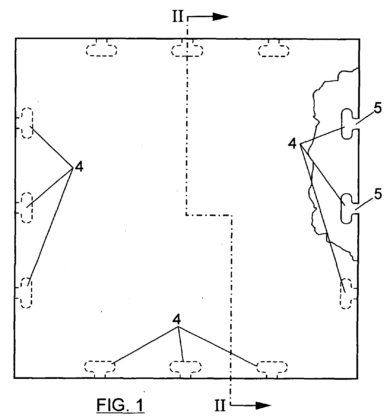
- Figures 1 and 2 show, as a non-limiting example, one of the pieces used to form the covering of the invention.
- This piece consists of two layers, a lower one 1, made of a material with certain capacity to elastically deform, and an upper one 2, made of ceramic material, both of them having an equal contour and joined together by an adhesive 3.
- the lower layer 1 will preferably be made of EVA.
- the lower layer has, from its edges, equal recesses 4, which are arranged in the same position in all edges. These recesses will be preferably oblong, with the major axis parallel to the adjacent edge of the lower layer 1, where they will end through a choked outlet 5.
- the covering of the invention is completed with intermediate joining elements 6, figures 3 to 5 , which have a contour which is equal to the double of the contour of the recesses 4 with their outlet 5, and a thickness equal to that of the lower layer 1 of the covering pieces, these joining elements adopting an H shape, whose parallel branches 7 will correspond to the oblong contour of the recesses 4 and whose central branch 8 will correspond to the double of the choking or outlet 5 of the recesses.
- the recesses 4 and their outlet 5 are covered by the upper layer 2 of the covering pieces.
- figure 6 is a plan view of six pieces or tiles, in some of which the upper layer of the covering 2 has been partially suppressed, so that the recesses 5 an the intermediate joining elements 6 can be better appreciated.
- the covering will start laying a first piece or tile 9, under whose recesses 5 the intermediate joining elements 6 are located, figure 8 , pressing downwardly the piece 9 until its recesses 5 are coupled on the intermediate joining elements 6, which are thus partially housed in the lower layer 1, as shown in figure 9 , half of the intermediate joining element 6 protruding from it, to rest thereon another adjacent piece, 10 or 12, figure 6 , so that the recesses 5 of these adjacent pieces coincide on the protruding part of the intermediate joining element 6 fixed before the piece 9, thus attaining the successive coupling of the pieces which can follow the sequence shown in figure 6 , where a line comprising successive pieces 9, 10 and 11 is placed first and then, a second line of pieces 12, 13 and 14, always with intermediate joining elements 6 which are coupled in the recesses 5 facing the opposite edges of consecutive pieces, to serve as joining or connecting elements between said pieces, thus achieving that all the pieces which constitute the covering are consecutively engaged through joining elements 6.
- the mounting system described enables to dismount any of the pieces which constitute the covering without having to alter or modify the position of the adjacent pieces.
- the covering of the invention will offer a ceramic covering appearance, of high hardness, suitable to walk on it as soon as its laying is finished.
- the pieces or tiles which form the covering of the invention can have an angular profile 15 on the edges of the lower layer 2, made of elastically compressible material, such as PVC, which will enable to attain better settling between tiles and at the same time to obtain a visible surface showing total continuity.
- This profile can be configured as a peripherally adjusted frame on the edges of the upper layer 2.
Abstract
Description
- The present invention refers to a demountable floor covering, and more specifically, to a covering of the kind made up of independent pieces and intermediate joining elements, which is placed dry on leveled floors, allowing an instant and clean laying, without using joining materials or producing debris.
- The covering of the invention is especially suitable for indoors, on leveled pavement, both on new work and on already existing pavement.
- There exist known floor coverings of the kind exposed, suitable for dry mounting. These coverings generally consist of wood pieces, which can have along their edges tongue and groove joints which secure the fixing between consecutive pieces, or otherwise use straps or auxiliary elements which serve as joining means between the covering pieces.
- In any case, a wood covering is attained which can be unsuitable for many applications, as it cannot adequately bear static and dynamic loads without being damaged. Besides, the coverings obtained with the pieces indicated prevent obtaining surfaces of another nature and are generally not conceived as demountable coverings.
- The object of the present invention is a floor covering, which can be dry laid and is easily mounted, engaging the constitutive pieces with the help of intermediate elements which secure its laying, without any risk of accidental uplifts, but enabling at all times to completely or partially dismount the covering. Besides, the covering of the invention offers a ceramic surface on which it is possible to walk, with high hardness and which can bear elastic and dynamic loads without any risk of being damaged.
- As indicated before, the covering of the invention belongs to the type consisting of independent pieces and intermediate joining elements.
- The independent pieces, according to the invention, consist of a lower shock-absorbing layer and a resistant upper covering layer, having both of them a coinciding contour and being joined together by means of an adhesive. The lower layer has discontinuous recesses from its edges, with choked outlet, being said recesses covered by the upper covering layer.
- As regards the intermediate joining elements, their contour is equal to the double of the contour of the recesses of the lower shock-absorbing layer, and their thickness is equal to that of said layer.
- The lower layer will preferably consist of an elastically deformable material, such as EVA (Ethylene Vinyl Acetate) which, due to its nature, decisively contributes in aspects such as the acoustics and ergonomic characteristics of the system.
- As regards the upper covering layer it will be ceramic and define the visible surface of the covering pieces, offering a surface with great resistance to any kind of external action.
- With the aforementioned constitution, the pieces that form the covering offer a ceramic tile aspect.
- The intermediate joining elements can be of the same nature as the lower shock-absorbing layer of the pieces that form the covering or they can be rigid, and they constitute connecting elements between consecutive pieces of the covering.
- The recesses of the lower shock-absorbing layer of the covering pieces can have an oblong contour, with a major axis parallel to the adjacent edge of the lower shock-absorbing layer, which will end in said edge through a passage which is thinner than the length of said axis. The intermediate joining elements will have a contour equal to the double of said recess contour, as it has already been indicated, adopting a double H configuration, with rounded edges.
- With the aforementioned constitution, in order to lay the covering the pieces or tiles are consecutively placed on the floor, inserting the intermediate joining elements on the recesses of the first piece laid on the floor, and next laying the consecutive piece or tile so that the recesses thereof coincide with the protruding portions of the intermediate joining elements fixed to the previous piece, exerting pressure downwardly until it is fit on said intermediate joining elements. Always through a slight pressure, the pieces or tiles are coupled in the corresponding parts of the intermediate joining elements. Once the covering has been finished, all the pieces forming it will be engaged to one another, through intermediate joining elements, being possible to use said covering immediately, obtaining a completely dry ceramic floor-laying.
- The laying of the covering of the invention is carried out without generating any debris and without being necessary to carry out works, thus reducing installation costs. Thanks to its nature, the covering obtained is suitable for the maintenance of underfloor heating and installations that require inspection, since the tiles can be removed or lifted without altering contiguous ones.
- Thanks to its versatility, the covering of the invention can be applied in the domestic field or in any other kind of establishments, either public or private ones, and it can be specially applied on those surfaces which frequently change their appearance such as stores, malls, etc.
- The nature of the lower layer which forms part of the pieces or tiles that constitute the covering of the invention, made of elastic materials, offers excellent energy restitution, thus offering greater comfort.
- The pieces or tiles that form the covering of the invention can also have on the edges of the upper layer an angular profile of elastically compressible material, such as PVC, which can be conceived as an adjustable frame of the upper layer edges and which will enable to attain better settling of the pieces between one another and at the same time to give complete continuity to the external aspect of the covering surface.
- The attached drawings show a non-limiting example of an embodiment, which will allow a better understanding of the characteristics and advantages of the covering of the invention, being as follows:
-
Figure 1 shows a top plan view of a piece to form the covering of the invention, with a partially suppressed upper layer. -
Figure 2 shows a cross section of the same piece, according to the cutting line II-II offigure 1 . -
Figure 3 shows a perspective view of one of the intermediate joining elements between the pieces that form the covering. -
Figure 4 is a plan view of the same intermediate joining element. -
Figure 5 is a section of an intermediate joining element, according to the cutting line V-V offigure 4 . -
Figure 6 shows a schematic plan view of the system of laying and joining between the pieces or tiles that form the covering of the invention. -
Figure 7 is a partial section of the covering of the invention, obtained according to the cutting line VII-VII offigure 6 . -
Figures 8 and 9 show two successive phases of the mounting of the pieces that form the covering of the invention. -
Figure 10 is a partial perspective of one of the pieces that form part of the covering of the invention, with an angular adjustment profile coupled to the edges of the upper layer. -
Figures 1 and 2 show, as a non-limiting example, one of the pieces used to form the covering of the invention. This piece consists of two layers, a lower one 1, made of a material with certain capacity to elastically deform, and an upper one 2, made of ceramic material, both of them having an equal contour and joined together by an adhesive 3. Thelower layer 1 will preferably be made of EVA. - The lower layer has, from its edges,
equal recesses 4, which are arranged in the same position in all edges. These recesses will be preferably oblong, with the major axis parallel to the adjacent edge of thelower layer 1, where they will end through a chokedoutlet 5.
The covering of the invention is completed with intermediate joiningelements 6,figures 3 to 5 , which have a contour which is equal to the double of the contour of therecesses 4 with theiroutlet 5, and a thickness equal to that of thelower layer 1 of the covering pieces, these joining elements adopting an H shape, whoseparallel branches 7 will correspond to the oblong contour of therecesses 4 and whosecentral branch 8 will correspond to the double of the choking oroutlet 5 of the recesses. - The
recesses 4 and theiroutlet 5 are covered by theupper layer 2 of the covering pieces. - For the formation of a covering with the pieces or tiles of
figures 1 and 2 and the intermediate connecting elements offigures 3 to 5 , they are all laid as shown infigure 6 , which is a plan view of six pieces or tiles, in some of which the upper layer of thecovering 2 has been partially suppressed, so that therecesses 5 an the intermediate joiningelements 6 can be better appreciated. - The covering will start laying a first piece or
tile 9, under whoserecesses 5 the intermediate joiningelements 6 are located,figure 8 , pressing downwardly thepiece 9 until itsrecesses 5 are coupled on the intermediate joiningelements 6, which are thus partially housed in thelower layer 1, as shown infigure 9 , half of the intermediate joiningelement 6 protruding from it, to rest thereon another adjacent piece, 10 or 12,figure 6 , so that therecesses 5 of these adjacent pieces coincide on the protruding part of the intermediate joiningelement 6 fixed before thepiece 9, thus attaining the successive coupling of the pieces which can follow the sequence shown infigure 6 , where a line comprisingsuccessive pieces pieces elements 6 which are coupled in therecesses 5 facing the opposite edges of consecutive pieces, to serve as joining or connecting elements between said pieces, thus achieving that all the pieces which constitute the covering are consecutively engaged through joiningelements 6. - The mounting system described enables to dismount any of the pieces which constitute the covering without having to alter or modify the position of the adjacent pieces.
- The covering of the invention will offer a ceramic covering appearance, of high hardness, suitable to walk on it as soon as its laying is finished.
- As shown in
figure 10 , the pieces or tiles which form the covering of the invention can have anangular profile 15 on the edges of thelower layer 2, made of elastically compressible material, such as PVC, which will enable to attain better settling between tiles and at the same time to obtain a visible surface showing total continuity. This profile can be configured as a peripherally adjusted frame on the edges of theupper layer 2.
Claims (9)
- Demountable floor covering, comprising independent pieces and intermediate joining elements, characterized in that the independent pieces comprise a lower shock-absorbing layer and a resistant covering upper layer, both of them having a coinciding contour and being joined together through an adhesive; whose lower layer has recesses from its edges, with a choked outlet, being said recesses covered by the covering upper layer; and whose intermediate joining elements have a contour equal to the double of the contour of the recesses and a thickness equal to that of the lower shock-absorbing layer of the tiles.
- Covering according to claim 1, characterized in that said recesses are arranged in number and position coinciding with all the edges of the lower layer of the pieces.
- Covering according to claim 1, characterized in that the lower layer is made up of an elastically deformable material.
- Covering according to claim 3, characterized in that the lower layer consists of an EVA plate.
- Covering according to claim 1, characterized in that the upper layer of the independent pieces is ceramic.
- Covering according to the preceding claims, characterized in that the recesses have an oblong contour, with a major axis parallel to the adjacent edge of the lower shock-absorbing layer, which ends on said edge through a passage which is thinner than the length of said axis.
- Covering according to claim 1, characterized in that on the edges of the lower layer there is an angular profile made of elastically compressible material.
- Covering according to claim 7, characterized in that the angular profiles attached to the four edges of the upper layer of each piece are joined together at their ends, forming an adjustable frame on the contour of said upper layer.
- Covering according to the preceding claims, characterized in that the intermediate joining elements adopt a configuration similar to an H.
Applications Claiming Priority (1)
| Application Number | Priority Date | Filing Date | Title |
|---|---|---|---|
| ES200930095A ES2357124B1 (en) | 2009-04-24 | 2009-04-24 | REMOVABLE SOIL COATING |
Publications (2)
| Publication Number | Publication Date |
|---|---|
| EP2243895A2 true EP2243895A2 (en) | 2010-10-27 |
| EP2243895A3 EP2243895A3 (en) | 2012-07-25 |
Family
ID=42549442
Family Applications (1)
| Application Number | Title | Priority Date | Filing Date |
|---|---|---|---|
| EP09380196A Withdrawn EP2243895A3 (en) | 2009-04-24 | 2009-12-23 | Demountable floor covering |
Country Status (3)
| Country | Link |
|---|---|
| US (1) | US20100269441A1 (en) |
| EP (1) | EP2243895A3 (en) |
| ES (1) | ES2357124B1 (en) |
Cited By (3)
| Publication number | Priority date | Publication date | Assignee | Title |
|---|---|---|---|---|
| JP2018035575A (en) * | 2016-08-31 | 2018-03-08 | 株式会社山仙 | Tool for preventing tatami mat from sliding |
| EP3449984A1 (en) | 2017-09-04 | 2019-03-06 | Trocellen GmbH | Mat system, especially for sports purposes |
| IT201900020751A1 (en) * | 2019-11-11 | 2021-05-11 | Artimo S R L | MODULABLE RACE TRACK FOR KARTRODOMES |
Families Citing this family (3)
| Publication number | Priority date | Publication date | Assignee | Title |
|---|---|---|---|---|
| PT2602096E (en) | 2010-08-05 | 2014-03-05 | Butech Building Technology S A | Process for producing pieces of removable floor covering and removable floor covering |
| DE102014108565A1 (en) * | 2014-06-18 | 2015-12-24 | Trocellen Gesellschaft Mit Beschränkter Haftung | Sports mat system |
| USD970055S1 (en) | 2021-04-25 | 2022-11-15 | James Loughran | Modular floor panel locking system |
Family Cites Families (19)
| Publication number | Priority date | Publication date | Assignee | Title |
|---|---|---|---|---|
| US716865A (en) * | 1902-05-14 | 1902-12-30 | Henri Choquet | Interlocking bricks. |
| US1149708A (en) * | 1914-06-19 | 1915-08-10 | Aaron Woloshin | Interlocking floor and panel. |
| US3452959A (en) * | 1967-08-31 | 1969-07-01 | Sadao Ishikawa | Combinational plastic hanger-board construction |
| GB1350754A (en) * | 1970-04-21 | 1974-04-24 | British Ceramic Res Ass | Tile-fixing |
| JPH0629340Y2 (en) * | 1989-08-08 | 1994-08-10 | 株式会社ピーシープランニング | Simple tile laying structure |
| SE514645C2 (en) * | 1998-10-06 | 2001-03-26 | Perstorp Flooring Ab | Floor covering material comprising disc-shaped floor elements intended to be joined by separate joint profiles |
| US6413618B1 (en) * | 1999-05-11 | 2002-07-02 | Congoleum Corporation | Laminated glass floor tile and flooring made therefrom and method for making same |
| US6453632B1 (en) * | 1999-08-09 | 2002-09-24 | Chin-Chih Huang | Wooden floor board |
| FR2823781B1 (en) * | 2001-04-19 | 2003-12-12 | Zhi Wen Tseng | WOODEN FLOOR STRUCTURE |
| DE20107338U1 (en) * | 2001-04-28 | 2001-06-28 | Schulze Zuralst Karl | Flexible floor covering system |
| US20020170259A1 (en) * | 2001-05-15 | 2002-11-21 | Ferris Stephen M. | Interlocking sidewalk block system |
| DE10253553A1 (en) * | 2002-03-22 | 2003-10-02 | Frieder Kattwinkel | Floating floor covering consists of top floor held onto support layer by massed of elastic adhesive accommodated in grooves in support layer |
| US20040031225A1 (en) * | 2002-08-14 | 2004-02-19 | Gregory Fowler | Water resistant tongue and groove flooring |
| DE10243196B4 (en) * | 2002-09-18 | 2007-03-22 | Kaindl Flooring Gmbh | Panels with connection bracket |
| ITPD20020249A1 (en) * | 2002-10-01 | 2004-04-02 | Marco Claudio Valerio | SELF-LAYING MODULAR ELEMENT STRUCTURE FOR FLOORING, PARTICULARLY IN STONE OR SIMILAR MATERIAL. |
| DE20313661U1 (en) * | 2003-09-05 | 2003-11-13 | Kaindl Wals M | Panel with protected V-groove |
| US7347788B2 (en) * | 2004-03-16 | 2008-03-25 | Crowson Enterprises Llc | Synthetic ice surface systems and methods thereof |
| EP1934417B1 (en) * | 2005-10-03 | 2012-05-23 | Tarkett SAS | Kit for the construction of a covering surface |
| WO2007129211A2 (en) * | 2006-05-10 | 2007-11-15 | Hermanus Petrus Alheit | Cladding product |
-
2009
- 2009-04-24 ES ES200930095A patent/ES2357124B1/en not_active Expired - Fee Related
- 2009-10-05 US US12/573,424 patent/US20100269441A1/en not_active Abandoned
- 2009-12-23 EP EP09380196A patent/EP2243895A3/en not_active Withdrawn
Non-Patent Citations (1)
| Title |
|---|
| None |
Cited By (6)
| Publication number | Priority date | Publication date | Assignee | Title |
|---|---|---|---|---|
| JP2018035575A (en) * | 2016-08-31 | 2018-03-08 | 株式会社山仙 | Tool for preventing tatami mat from sliding |
| EP3449984A1 (en) | 2017-09-04 | 2019-03-06 | Trocellen GmbH | Mat system, especially for sports purposes |
| WO2019043236A1 (en) | 2017-09-04 | 2019-03-07 | Trocellen Gmbh | Mat system, especially for sports purposes |
| US11318365B2 (en) | 2017-09-04 | 2022-05-03 | Trocellen Gmbh | Mat system, especially for sports purposes |
| IT201900020751A1 (en) * | 2019-11-11 | 2021-05-11 | Artimo S R L | MODULABLE RACE TRACK FOR KARTRODOMES |
| WO2021094936A1 (en) * | 2019-11-11 | 2021-05-20 | Artimo S.R.L. | Modular track for go-kart circuits |
Also Published As
| Publication number | Publication date |
|---|---|
| EP2243895A3 (en) | 2012-07-25 |
| ES2357124A1 (en) | 2011-04-19 |
| ES2357124B1 (en) | 2012-03-20 |
| US20100269441A1 (en) | 2010-10-28 |
Similar Documents
| Publication | Publication Date | Title |
|---|---|---|
| EP2243895A2 (en) | Demountable floor covering | |
| US20200190829A1 (en) | Support plate for installing tile | |
| US9328520B1 (en) | High strength in-floor decoupling membrane | |
| US8186116B2 (en) | Tile tray | |
| US5438809A (en) | Modular tile flooring system | |
| US8607532B2 (en) | Building component for forming a floor or wall coverings | |
| US8166726B2 (en) | Tile leveling process and apparatus | |
| US20120017528A1 (en) | Floor and tile system with pad | |
| CN104895293B (en) | Wood floor paving keel and fast paving method thereof | |
| JP2007182751A (en) | Tile | |
| US20080005988A1 (en) | Floor or wall covering | |
| US20130167463A1 (en) | Composite tile product | |
| US10753092B1 (en) | Fiber reinforced surface covering | |
| ITRE20070066A1 (en) | REMOVABLE SUPPORTS FOR OUTDOOR AND / OR INTERNAL FLOORS | |
| EP2402664A2 (en) | Radiant floor module | |
| US10435893B2 (en) | Method for laying tiles | |
| CN105804353A (en) | Architectural finish material capable of being installed rapidly | |
| US20100095619A1 (en) | Tile | |
| US20140144092A1 (en) | System and apparatus for installation of tile floor | |
| US20150308126A1 (en) | Extended kerf cut and spline restraint system for elevated flooring surfaces | |
| US20170321431A1 (en) | Hard flooring plank and wall panel plank | |
| US20030221388A1 (en) | Tile edging strip | |
| EP3369874B1 (en) | A modular floating screed with incorporated heating elements | |
| EP3124717A1 (en) | Modular floor laid by mechanical interlocking, mechanical interlocking laying method for a modular floor kit for the mechanical interlocking laying of a modular floor | |
| USRE22013E (en) | Means for joining constructional |
Legal Events
| Date | Code | Title | Description |
|---|---|---|---|
| PUAI | Public reference made under article 153(3) epc to a published international application that has entered the european phase |
Free format text: ORIGINAL CODE: 0009012 |
|
| AK | Designated contracting states |
Kind code of ref document: A2 Designated state(s): AT BE BG CH CY CZ DE DK EE ES FI FR GB GR HR HU IE IS IT LI LT LU LV MC MK MT NL NO PL PT RO SE SI SK SM TR |
|
| AX | Request for extension of the european patent |
Extension state: AL BA RS |
|
| PUAL | Search report despatched |
Free format text: ORIGINAL CODE: 0009013 |
|
| AK | Designated contracting states |
Kind code of ref document: A3 Designated state(s): AT BE BG CH CY CZ DE DK EE ES FI FR GB GR HR HU IE IS IT LI LT LU LV MC MK MT NL NO PL PT RO SE SI SK SM TR |
|
| AX | Request for extension of the european patent |
Extension state: AL BA RS |
|
| RIC1 | Information provided on ipc code assigned before grant |
Ipc: B32B 7/04 20060101ALI20120619BHEP Ipc: B32B 27/30 20060101ALI20120619BHEP Ipc: E04F 15/02 20060101AFI20120619BHEP |
|
| STAA | Information on the status of an ep patent application or granted ep patent |
Free format text: STATUS: THE APPLICATION IS DEEMED TO BE WITHDRAWN |
|
| 18D | Application deemed to be withdrawn |
Effective date: 20120703 |