EP2243813A1 - Liquid crystal composition containing polymerizable compound, and liquid crystal display element comprising the liquid crystal composition - Google Patents
Liquid crystal composition containing polymerizable compound, and liquid crystal display element comprising the liquid crystal composition Download PDFInfo
- Publication number
- EP2243813A1 EP2243813A1 EP09712083A EP09712083A EP2243813A1 EP 2243813 A1 EP2243813 A1 EP 2243813A1 EP 09712083 A EP09712083 A EP 09712083A EP 09712083 A EP09712083 A EP 09712083A EP 2243813 A1 EP2243813 A1 EP 2243813A1
- Authority
- EP
- European Patent Office
- Prior art keywords
- liquid crystal
- crystal composition
- ring
- carbon atoms
- polymerizable compound
- Prior art date
- Legal status (The legal status is an assumption and is not a legal conclusion. Google has not performed a legal analysis and makes no representation as to the accuracy of the status listed.)
- Granted
Links
- 0 CCc(cc(cc1)*(Oc(cc2)ccc2OC(C=C)=O)=O)c1OCCCCCCOC(C=C)=O Chemical compound CCc(cc(cc1)*(Oc(cc2)ccc2OC(C=C)=O)=O)c1OCCCCCCOC(C=C)=O 0.000 description 4
- DGGLMNQWUIAHAN-UHFFFAOYSA-N CC(C(C=C1OC)OC(c(cc2)ccc2OCCCCCCOC(C(C)=C)=O)=O)C=C1OC(CCc(cc1)ccc1OC(C=C)=O)=O Chemical compound CC(C(C=C1OC)OC(c(cc2)ccc2OCCCCCCOC(C(C)=C)=O)=O)C=C1OC(CCc(cc1)ccc1OC(C=C)=O)=O DGGLMNQWUIAHAN-UHFFFAOYSA-N 0.000 description 1
- KAGIRXVDTGQWKF-UHFFFAOYSA-N CC(C(OCCCCCCOc(cc1)ccc1C(O)=O)=O)=C Chemical compound CC(C(OCCCCCCOc(cc1)ccc1C(O)=O)=O)=C KAGIRXVDTGQWKF-UHFFFAOYSA-N 0.000 description 1
- QPODDLAKBPKBOT-UHFFFAOYSA-N CCCc(cc(cc1)O)c1OC(c1ccc(cc(cc2)OC(C(C)=C)=O)c2c1)=O Chemical compound CCCc(cc(cc1)O)c1OC(c1ccc(cc(cc2)OC(C(C)=C)=O)c2c1)=O QPODDLAKBPKBOT-UHFFFAOYSA-N 0.000 description 1
- AXZCLPSJTNGFNM-UHFFFAOYSA-N CCCc(cc(cc1)OO)c1OC(c(cc1)cc(cc2)c1cc2OC(C(C)=C)=O)=O Chemical compound CCCc(cc(cc1)OO)c1OC(c(cc1)cc(cc2)c1cc2OC(C(C)=C)=O)=O AXZCLPSJTNGFNM-UHFFFAOYSA-N 0.000 description 1
- MSSFJGDOBFDEOL-UHFFFAOYSA-N CCCc1cc(OC(c(cc2)cc(cc3)c2cc3OCCCCCCOC(C=C)=O)=O)ccc1OC(c1ccc(cc(cc2)OC(C=C)=O)c2c1)=O Chemical compound CCCc1cc(OC(c(cc2)cc(cc3)c2cc3OCCCCCCOC(C=C)=O)=O)ccc1OC(c1ccc(cc(cc2)OC(C=C)=O)c2c1)=O MSSFJGDOBFDEOL-UHFFFAOYSA-N 0.000 description 1
- ZPBGRNSYFRVEFS-UHFFFAOYSA-N CCCc1cc(OC(c(cc2)ccc2OCCCCCCOC(C(C)=C)=O)=O)ccc1OC(c1ccc(cc(cc2)OC(C(C)=C)=O)c2c1)=O Chemical compound CCCc1cc(OC(c(cc2)ccc2OCCCCCCOC(C(C)=C)=O)=O)ccc1OC(c1ccc(cc(cc2)OC(C(C)=C)=O)c2c1)=O ZPBGRNSYFRVEFS-UHFFFAOYSA-N 0.000 description 1
Images
Classifications
-
- C—CHEMISTRY; METALLURGY
- C09—DYES; PAINTS; POLISHES; NATURAL RESINS; ADHESIVES; COMPOSITIONS NOT OTHERWISE PROVIDED FOR; APPLICATIONS OF MATERIALS NOT OTHERWISE PROVIDED FOR
- C09K—MATERIALS FOR MISCELLANEOUS APPLICATIONS, NOT PROVIDED FOR ELSEWHERE
- C09K19/00—Liquid crystal materials
- C09K19/04—Liquid crystal materials characterised by the chemical structure of the liquid crystal components, e.g. by a specific unit
- C09K19/06—Non-steroidal liquid crystal compounds
- C09K19/08—Non-steroidal liquid crystal compounds containing at least two non-condensed rings
- C09K19/10—Non-steroidal liquid crystal compounds containing at least two non-condensed rings containing at least two benzene rings
- C09K19/20—Non-steroidal liquid crystal compounds containing at least two non-condensed rings containing at least two benzene rings linked by a chain containing carbon and oxygen atoms as chain links, e.g. esters or ethers
- C09K19/2007—Non-steroidal liquid crystal compounds containing at least two non-condensed rings containing at least two benzene rings linked by a chain containing carbon and oxygen atoms as chain links, e.g. esters or ethers the chain containing -COO- or -OCO- groups
-
- C—CHEMISTRY; METALLURGY
- C09—DYES; PAINTS; POLISHES; NATURAL RESINS; ADHESIVES; COMPOSITIONS NOT OTHERWISE PROVIDED FOR; APPLICATIONS OF MATERIALS NOT OTHERWISE PROVIDED FOR
- C09K—MATERIALS FOR MISCELLANEOUS APPLICATIONS, NOT PROVIDED FOR ELSEWHERE
- C09K19/00—Liquid crystal materials
- C09K19/04—Liquid crystal materials characterised by the chemical structure of the liquid crystal components, e.g. by a specific unit
- C09K19/06—Non-steroidal liquid crystal compounds
- C09K19/08—Non-steroidal liquid crystal compounds containing at least two non-condensed rings
- C09K19/30—Non-steroidal liquid crystal compounds containing at least two non-condensed rings containing saturated or unsaturated non-aromatic rings, e.g. cyclohexane rings
- C09K19/3001—Cyclohexane rings
- C09K19/3066—Cyclohexane rings in which the rings are linked by a chain containing carbon and oxygen atoms, e.g. esters or ethers
- C09K19/3068—Cyclohexane rings in which the rings are linked by a chain containing carbon and oxygen atoms, e.g. esters or ethers chain containing -COO- or -OCO- groups
-
- C—CHEMISTRY; METALLURGY
- C09—DYES; PAINTS; POLISHES; NATURAL RESINS; ADHESIVES; COMPOSITIONS NOT OTHERWISE PROVIDED FOR; APPLICATIONS OF MATERIALS NOT OTHERWISE PROVIDED FOR
- C09K—MATERIALS FOR MISCELLANEOUS APPLICATIONS, NOT PROVIDED FOR ELSEWHERE
- C09K19/00—Liquid crystal materials
- C09K19/04—Liquid crystal materials characterised by the chemical structure of the liquid crystal components, e.g. by a specific unit
- C09K19/06—Non-steroidal liquid crystal compounds
- C09K19/32—Non-steroidal liquid crystal compounds containing condensed ring systems, i.e. fused, bridged or spiro ring systems
- C09K19/322—Compounds containing a naphthalene ring or a completely or partially hydrogenated naphthalene ring
-
- C—CHEMISTRY; METALLURGY
- C09—DYES; PAINTS; POLISHES; NATURAL RESINS; ADHESIVES; COMPOSITIONS NOT OTHERWISE PROVIDED FOR; APPLICATIONS OF MATERIALS NOT OTHERWISE PROVIDED FOR
- C09K—MATERIALS FOR MISCELLANEOUS APPLICATIONS, NOT PROVIDED FOR ELSEWHERE
- C09K19/00—Liquid crystal materials
- C09K19/04—Liquid crystal materials characterised by the chemical structure of the liquid crystal components, e.g. by a specific unit
- C09K2019/0444—Liquid crystal materials characterised by the chemical structure of the liquid crystal components, e.g. by a specific unit characterized by a linking chain between rings or ring systems, a bridging chain between extensive mesogenic moieties or an end chain group
- C09K2019/0448—Liquid crystal materials characterised by the chemical structure of the liquid crystal components, e.g. by a specific unit characterized by a linking chain between rings or ring systems, a bridging chain between extensive mesogenic moieties or an end chain group the end chain group being a polymerizable end group, e.g. -Sp-P or acrylate
-
- C—CHEMISTRY; METALLURGY
- C09—DYES; PAINTS; POLISHES; NATURAL RESINS; ADHESIVES; COMPOSITIONS NOT OTHERWISE PROVIDED FOR; APPLICATIONS OF MATERIALS NOT OTHERWISE PROVIDED FOR
- C09K—MATERIALS FOR MISCELLANEOUS APPLICATIONS, NOT PROVIDED FOR ELSEWHERE
- C09K2323/00—Functional layers of liquid crystal optical display excluding electroactive liquid crystal layer characterised by chemical composition
-
- G—PHYSICS
- G02—OPTICS
- G02F—OPTICAL DEVICES OR ARRANGEMENTS FOR THE CONTROL OF LIGHT BY MODIFICATION OF THE OPTICAL PROPERTIES OF THE MEDIA OF THE ELEMENTS INVOLVED THEREIN; NON-LINEAR OPTICS; FREQUENCY-CHANGING OF LIGHT; OPTICAL LOGIC ELEMENTS; OPTICAL ANALOGUE/DIGITAL CONVERTERS
- G02F1/00—Devices or arrangements for the control of the intensity, colour, phase, polarisation or direction of light arriving from an independent light source, e.g. switching, gating or modulating; Non-linear optics
- G02F1/01—Devices or arrangements for the control of the intensity, colour, phase, polarisation or direction of light arriving from an independent light source, e.g. switching, gating or modulating; Non-linear optics for the control of the intensity, phase, polarisation or colour
- G02F1/13—Devices or arrangements for the control of the intensity, colour, phase, polarisation or direction of light arriving from an independent light source, e.g. switching, gating or modulating; Non-linear optics for the control of the intensity, phase, polarisation or colour based on liquid crystals, e.g. single liquid crystal display cells
- G02F1/137—Devices or arrangements for the control of the intensity, colour, phase, polarisation or direction of light arriving from an independent light source, e.g. switching, gating or modulating; Non-linear optics for the control of the intensity, phase, polarisation or colour based on liquid crystals, e.g. single liquid crystal display cells characterised by the electro-optical or magneto-optical effect, e.g. field-induced phase transition, orientation effect, guest-host interaction or dynamic scattering
- G02F1/13775—Polymer-stabilized liquid crystal layers
Definitions
- This invention relates to a liquid crystal composition having a specific liquid crystal composition and a polymerizable liquid crystal compound having a (meth)acryloyl group as a polymerizable group and an electrooptical display device having the liquid crystal composition sandwiched between substrates.
- LCDs liquid crystal displays
- ⁇ n optical (refractive index) anisotropy
- ⁇ dielectric anisotropy
- ⁇ dielectric anisotropy
- a liquid crystal compound exhibits an inherent liquid crystal phase between a solid phase and a liquid phase. Liquid crystal phases are roughly classified into a nematic phase, a smectic phase, and a cholesteric phase.
- Display modes applied to LCDs typically include twist nematic (TN), super twist nematic (STN), dynamic scatter (DS), guest host (GH), in-plane switching (IPS), optically compensated birefringence (OCB), electrically controlled birefringence (ECB), vertical alignment (VA), color super homeotropic (CSH), and ferroelectric liquid crystal (FLC).
- TN twist nematic
- STN super twist nematic
- DS dynamic scatter
- guest host GH
- in-plane switching IPS
- OOB optically compensated birefringence
- ECB electrically controlled birefringence
- VA vertical alignment
- CSH color super homeotropic
- FLC ferroelectric liquid crystal
- AM-LCDs mostly use a TN mode liquid crystal cell in which molecules of a liquid crystal material having a positive dielectric anisotropy ( ⁇ ) are aligned to be in parallel to the substrates and twisted by 90 degrees between the opposing substrates.
- ⁇ positive dielectric anisotropy
- the TN mode LCDs have a disadvantage of a narrow viewing angle, and various studies have been made to increase the viewing angle.
- VA mode LCDs particularly MVA and EVA mode LCDs described in non-patent documents 1 and 2 (see below) have been developed as an alternative to TN mode LCDs and succeeded in greatly improving viewing angle characteristics.
- these VA mode LCDs molecules of a liquid crystal material having negative dielectric anisotropy between two substrate are aligned perpendicular to the substrates and, with a voltage applied, the tilt direction of the liquid crystal directors are controlled by ribs or slits made on the surface of the substrates.
- an LCD made by using a liquid crystal material containing a monomer or an oligomer polymerizable on light or heat application has been proposed as in patent document 1 (see below).
- An LCD of this type is produced by sealing the liquid crystal material in between two substrates and polymerizing the polymerizable component while adjusting the voltage applied to the liquid crystal layer thereby to decide the alignment direction of the liquid crystal molecules.
- VHR voltage holding ratio during a frame period
- Patent document 1 discloses a VA mode LCD with reduced burn-in and a composition used therefor.
- Patent document 2 discloses an alignment film providing a VA mode LCD having a high VHR. With these techniques, nevertheless, a satisfactory response speed is not obtained.
- Patent documents 3 and 4 below disclose a VA mode liquid crystal composition but have no mention of the use of a polymerizable liquid crystal compound having a (meth)acryloyl group as a polymerizable group.
- Patent document 5 below proposes a polymerizable liquid crystal compound but neither describes nor suggests the use of the compound in a liquid crystal composition having negative dielectric anisotropy ( ⁇ ).
- An object of the invention is to provide a liquid crystal composition that does not deteriorate in reliability (VHR) on being irradiated with energy rays, such as ultraviolet rays, and affords an LCD capable of high speed response.
- VHR deteriorate in reliability
- a liquid crystal composition comprising 100 parts by mass of a nematic liquid crystal composition having negative dielectric anisotropy ( ⁇ ) and 0.01 to 3 parts by mass of a polymerizable compound represented by general formula (I):
- ring C 1 , ring C 2 , and ring C 3 each independently represent a benzene ring, a cyclohexane ring, or a naphthalene ring, one or more hydrogen atoms of each of which are optionally substituted with an alkyl group having 1 to 3 carbon atoms, an alkoxy group having 1 to 3 carbon atoms, an acyl group having 1 to 3 carbon atoms, or a halogen atom;
- M 1 and M 2 each independently represent a hydrogen atom or a methyl group;
- Z 1 represents a direct bond, -L 1 -, -L 1 O-, -L 1 O-CO-, or -L 1 CO-O-, and
- Z 4 represents a direct bond, -L 2 -, -OL 2 -, -O-COL 2 -, or -CO-OL 2 -, provided that at least one of Z 1 and Z 4 is not a direct bond;
- the invention also provides an electrooptical display device fabricated by sandwiching the liquid crystal composition of the invention between two substrates at least one of which has an electrode to apply a voltage to liquid crystal molecules, irradiating the liquid crystal composition with an energy ray to cause the polymerizable compound represented by general formula (I) present in the liquid crystal composition to polymerize.
- the liquid crystal composition of the invention comprises 100 parts by mass of a nematic liquid crystal composition having negative dielectric anisotropy ( ⁇ ) and 0.01 to 3 parts by mass of a polymerizable compound represented by general formula (I).
- the liquid crystal composition preferably contains 0.05 to 2 parts by mass of the polymerizable compound per 100 parts by mass of the nematic liquid crystal composition. If the content of the polymerizable compound is less than 0.01 parts by mass, the response is slow. If it is more than 3 parts by mass, the composition has poor solubility. More preferably, the content of the polymerizable compound is from 0.05 to 1 part by mass per 100 pats by mass of the nematic liquid crystal composition. With this content the composition achieves a particularly high VHR.
- Examples of the C1-C3 alkyl group, the C1-C3 alkoxy group, and the C1-C3 acyl group that may be substituted for the hydrogen atom of the rings C 1 , C 2 , and C 3 in formula (I) include methyl, ethyl, propyl, and isopropyl; methoxy, ethoxy, propoxy, and isopropoxy; and formyl, acetyl, and propionyl, respectively.
- Examples of the halogen atom that may be substituted for the hydrogen atom of the rings C 1 , C 2 , and C 3 in formula (I) include fluorine, chloride, bromine, and iodine.
- Examples of the optionally branched C1-C10 alkylene group represented by L 1 and L 2 in formula (I) include methylene, ethylene, propylene, trimethylene, tetramethylene, butane-1,3-diyl, 2-methylpropane-1,3-diyl, 2-methylbutane-1,3-diyl, pentane-2,4-diyl, pentane-1,4-diyl, 3-methylbutane-1,4-diyl, 2-methylpentane-1,4-diyl, pentamethylene, hexamethylene, heptamethylene, octamethylene, nonamethylene, and decamethylene.
- Examples of the direct bond, the ester bond, the ether bond, the optionally branched, saturated or unsaturated C2-C8 alkylene group, or a combination thereof include -CO-O-, -O-CO-, -O-CO-O-, -(CH 2 ) a -, -(CH 2 ) a -O-, -O-(CH 2 ) a -, -O-(CH 2 ) a -O-, -(CH 2 ) a -O-CO-, -CO-O-(CH 2 ) a -, -(CH 2 ) a -CO-O-, -O-CO-(CH 2 ) a -, -(CH 2 ) a -O-CO-O-, -O-CO-O-(CH 2 ) a -, -(CH 2 ) a -O-CO-O-, -O-CO-O-(CH 2 )
- the compound of formula (I) in which at least one hydrogen atom of the rings C 1 , C 2 , and C 3 is substituted by C1-C3 alkyl, C1-C3 alkoxy, C1-C3 acyl, or halogen is preferred as having good solubility in the nematic liquid crystal compound.
- the expression "when Z 1 and Z 4 are the same” means that Z 1 and Z 4 are a combination of -L 1 - and -L 2 -, a combination of -L 1 O- and -OL 2 -, a combination of -L 1 O-CO- and -CO-OL 2 -, or a combination of -L 1 CO-O- and -O-COL 2 -.
- the polymerizable compound of formula (I) be dissolved in the nematic liquid crystal composition at room temperature because heating the system for facilitating dissolving can invite reduction in VHR. From this point of view, it is preferred for the polymerizable compound to be used to have good solubility.
- the polymerizable compounds of formula (I) in which p and q are both 1; the polymerizable compounds of formula (I) in which either M 1 or M 2 is methyl; and the polymerizable compounds of formula (I) in which M 1 and M 2 are both methyl are still preferred in terms of superior reliability of the resulting liquid crystal compositions. Those in which M 1 and M 2 are both methyl are particularly preferred for their high polymerization reactivity.
- Examples of the polymerizable compound of general formula (I) include, but are not limited to, the following compounds.
- the nematic liquid crystal composition having negative dielectric anisotropy ( ⁇ ) that can be used in the invention may be prepared using any appropriate known liquid crystal compound so as to exhibit negative dielectric anisotropy ( ⁇ ).
- a nematic liquid crystal composition containing a liquid crystal compound represented by general formula (II) shown below in a proportion of 30 to 100% by mass is preferred for its excellent liquid crystal display characteristics.
- the liquid crystal compounds represented by formula (II) may be used either individually or as a combination of two or more thereof.
- Examples of the C1-C3 alkyl group and the C1-C3 alkoxy group that may be substituted for the hydrogen atom of the rings B 1 , B 2 , B 3 , and B 4 in formula (II) include those enumerated above for the C1-C3 alkyl group and the C1-C3 alkoxy group that may be substituted for the hydrogen atom of the rings C 1 , C 2 , and C 3 in formula (I).
- Examples of the C1-C6 alkyl group represented by R 3 and R 4 in formula (II) include methyl, ethyl, propyl, isopropyl, butyl, s-butyl, t-butyl, isobutyl, amyl, isoamyl, t-amyl, hexyl, 2-hexyl, and 3-hexyl.
- Examples of the C2-C6 alkenyl group represented by R 3 and R 4 in formula (II) include vinyl, 1-methylethenyl, 2-methylethenyl, 2-propenyl, 1-methyl-3-propenyl, 3-butenyl, 1-methyl-3-butenyl, isobutenyl, 3-pentenyl, and 4-hexenyl.
- liquid crystal compounds of general formula (II) preferred is the one represented by general formula (III), for the nematic liquid crystal composition containing the compound of formula (III) provides particularly excellent liquid crystal display characteristics.
- ring B 1 , ring B 2 , Y 1 , Y 2 , Y 3 , R 3 , R 4 , j, k, m, and n are as defined for general formula (II);
- E 1 , E 2 , E 3 , and E 4 each represent hydrogen, chlorine, fluorine, -CF 3 , -OCF 3 , or -OCF 2 H, provided that at least one of the E 1 /E 2 combination and the E 3 /E 4 combination consists of other than hydrogen.
- liquid crystal compounds of formula (III) preferred is the one in which E 1 , E 2 , E 3 , and E 4 are each hydrogen or fluorine, namely the one in which one of the E 1 /E 2 combination and the E 3 /E 4 combination consists solely of fluorine atoms with the other consisting solely of hydrogen atoms or the one in which both the combinations consist solely of fluorine atoms, for the nematic liquid crystal composition containing this compound provides further improved display characteristics, such as response time, and reliability.
- Examples of the compound represented by formula (II) include, but are not limited to, the following compounds.
- R 13 is C2-C5 alkyl
- R 14 is C1-C5 alkyl.
- R 23 is C2-C5 alkyl
- R 24 is C1-C5 alkyl
- the nematic liquid crystal composition having negative dielectric anisotropy ( ⁇ ) further contain a liquid crystal compound represented by general formula (IV) shown below for providing further improved liquid crystal display characteristics.
- the content of the compound of formula (IV) is preferably 5% to 50% by mass, more preferably 10% to 50% by mass. When used in an amount less than 5%, the compound produces insufficient effects of use. Use of more than 50% of the compound tends to result in a reduction in VHR.
- Examples of the C1-C3 alkyl group and the C1-C3 alkoxy group that may be substituted for the hydrogen atom of the rings A 1 , A 2 , and A 3 in formula (IV) include those enumerated above for the C1-C3 alkyl group and the C1-C3 alkoxy group that may be substituted for the hydrogen atom of the rings C 1 , C 2 , and C 3 in formula (I).
- Examples of the C1-C6 alkyl group and the C2-C6 alkenyl group represented by R 1 and R 2 in formula (IV) include those recited above for the C1-C6 alkyl group and the C2-C6 alkenyl group represented by R 3 and R 4 in formula (II).
- Examples of the compound represented by formula (IV) include, but are not limited to, the following compounds.
- R 11 and R 12 each represent a C 1-C6 alkyl or C2-C6 alkenyl.
- R 21 and R 22 each represent C2-C5 alkyl or C2-C6 alkenyl.
- the nematic liquid crystal composition for use in the liquid crystal composition of the invention may further contain other commonly used liquid crystal compounds within a range that secures negative dielectric anisotropy ( ⁇ ).
- liquid crystal compounds include, but are not limited to, the following compounds.
- W 1 is hydrogen or an optionally branched alkyl, alkoxy, alkenyl, alkenyloxy, alkynyl, alkynyloxy, alkoxyalkyl, alkanoyloxy, or alkoxycarbonyl group having 1 to 8 carbon atoms, each optionally being substituted with a halogen atom, a cyano group, etc.
- W 2 is cyano, halogen, or a group represented by W 1
- W 3 , W 4 , and W 5 are each hydrogen, halogen, or cyano, provided that the compounds corresponding to the general formulae (II) and (IV) are excluded.
- the liquid crystal composition of the invention may contain a photopolymerization initiator.
- the photopolymerization initiator for use in the invention may be any known compound, including benzoin ethers, such as benzoin butyl ether; benzyl ketals, such as benzyl dimethyl ketal; ⁇ -hydroxyacetophenones, such as 1-hydroxy-1-benzoylcyclohexane, 2-hydroxy-2-benzoylpropane, and 2-hydroxy-2-(4'-isopropyl)benzoylpropane; chloroaceto phenones, such as 4-butylbenzoyltrichloromethane and 4-phenoxybenzoyldichloromethane; ⁇ -aminoacetophenones, such as 1-benzyl-1-dimethylamino-1-(4'-morpholinobenzoyl) propane, 2-morpholyl-2-(4'-methylmercapto)benzoylpropane, 9-n-butyl
- a combination of the photopolymerization initiator and a sensitizer is also preferably used.
- useful sensitizers are thioxanthone, phenothiazine, chlorothioxanthone, xanthone, anthracene, dipyhenylanthracene, and rubrene.
- the total amount of the photopolymerization initiator and/or the sensitizer, if added, is preferably 10 parts by mass or less, more preferably 5 parts by mass or less, even more preferably 0.1 to 3 parts by mass, per 100 parts by mass of the polymerizable compound of formula (I).
- Additives may be added to the liquid crystal composition of the invention where needed to improve characteristics of the polymerizable composition, including functional compounds, such as storage stabilizers, antioxidants, ultraviolet absorbers, infrared absorbers, fine particles of organic, inorganic or other materials, and polymers.
- functional compounds such as storage stabilizers, antioxidants, ultraviolet absorbers, infrared absorbers, fine particles of organic, inorganic or other materials, and polymers.
- the storage stabilizers serve to improve storage stability of the liquid crystal composition, including hydroquinone, hydroquinone monoalkyl ethers, tert-butyl catechols, pyrogallols, thiophenols, nitro compounds, 2-naphtylamines, and 2-hydroxynaphthalenes.
- the amount of the storage stabilizer, if used, is preferably 1 part by mass or less, more preferably 0.5 parts by mass or less, per 100 parts by mass of the polymerizable compound.
- antioxidants including hydroquinone, 2,6-di(tert-butyl)-p-cresol, 2,6-di(tert-butyl)phenol, triphenyl phosphite, and trialkyl phosphites.
- UV absorbers including salicylic ester compounds, benzophenol compounds, benzotriazole compounds, triazine compounds, cyanoacrylate compounds, and nickel complex salt compounds.
- the above mentioned additives may be used appropriately with no particular limitation as long as the characteristics of the resulting polymer are not impaired.
- the total amount of these optional components is not more than 30 parts by mass, more preferably 10 parts by mass or less, per 100 parts by mass of the sum of the nematic liquid crystal compound having negative dielectric anisotropy ( ⁇ ) and the polymerizable compound represented by the general formula (I).
- the liquid crystal composition of the invention is used by polymerizing the polymerizable compound by known processes using light, electromagnetic radiation, or heat.
- the preferred light include ultraviolet light, visible light, and infrared light.
- Electromagnetic radiation, such as electron beams and X rays, may also be used.
- ultraviolet light or visible light is preferred.
- a preferred wavelength range is from 150 to 500 nm, more preferably from 250 to 450 nm, even more preferably 300 to 400 nm.
- Light sources include low pressure mercury lamps (e.g., bactericidal lamps, fluorescent chemical lamps, and black lights), high pressure discharge lamps (e.g., high pressure mercury lamps and metal halide lamps), and short arc discharge lamps (ultrahigh pressure mercury lamps, xenon lamps, and mercury xenon lamps), with high pressure mercury lamps and ultrahigh pressure mercury lamps being preferred.
- the liquid crystal composition may be irradiated with the light as emitted from a light source or a light ray of a specific wavelength or light rays of a specific wavelength range selected through a filter.
- a preferred irradiation energy density is 10 to 50000 mJ/cm 2 , more preferably 10 to 20000 mJ/cm 2 .
- a preferred illuminance is 0.1 to 5000 mW/cm 2 , more preferably 1 to 2000 mW/cm 2 .
- the electrooptical display device of the present invention is then described.
- the electrooptical display device of the invention is produced by sandwiching the liquid crystal composition of the invention between two substrates at least one of which has an electrode for applying a voltage to liquid crystal molecules, irradiating the liquid crystal composition with an energy ray, such as an ultraviolet ray, to cause the polymerizable compound represented by general formula (I) to polymerize.
- the substrate may be selected as appropriate to the intended driving system and display system from those conventionally used in electrooptical display devices with no particularly restrictions.
- Examples of the energy ray include the above described light, electromagnetic radiation, and heat as well as an ultraviolet ray.
- the electrooptical display device of the invention may be of AM drive type or passive matrix (PM) drive type.
- An LCD driven in an AM or PM scheme is applicable to any of reflective, transmissive, and semi-transmissive LCDs.
- the electrooptical display device of the invention is also useful as a dynamic scattering (DS) mode device using a liquid crystal composition containing an electroconductive agent, a nematic curvilinear aligned phase (NCAP) device prepared by microencapsulating a liquid crystal composition, and a polymer dispersed (PD) device using a liquid crystal composition having a three dimensional network polymer structure, for example, a polymer network (PN) device.
- DS dynamic scattering
- NCAP nematic curvilinear aligned phase
- PD polymer dispersed
- PN polymer network
- the liquid crystal composition of the invention is particularly suited for use in AM LCDs having a display mode utilizing a negative dielectric anisotropy, such as a VA mode and an IPS mode, especially AM LCDs having a VA display mode.
- VA mode LCDs In VA mode LCDs, the direction of the electric field applied is perpendicular to the liquid crystal layer, while in IPS mode LCDs, the direction of the electric field is in parallel to the liquid crystal layer.
- the structure of VA mode LCDs is reported, e.g., in K. Ohmuro, S. Kataoka, T. Sasaki and Y. Koike, SID '97 Digest of Technical Papers, vol. 28, p. 845 (1997 ), and the structure of IPS mode LCDs is reported, e.g., in WO91/10936 ( U.S. Pat. No. 5,576,867 ).
- the electrooptical display devices having the liquid crystal composition of the invention are applicable to watches, calculators, measuring instruments, automotive panels, copiers, cameras, business machines, PDAs, notebook or desktop computer monitors, TV monitors, cell phones, light control glass, optical shutters, and replacement polarizers.
- the characteristics of the electrooptical display devices of the invention are particularly taken advantage of in applications to large PDAs, notebook or desktop computer monitors, and TV monitors.
- Nematic liquid crystal compositions having negative ⁇ for use in the invention were prepared in Reference Example. Polymerizable compounds of the invention and comparative polymerizable compounds were synthesized in Synthesis Examples. In Examples 1 and Comparative Examples 1, liquid crystal compositions containing a varied amount of a polymerizable compound of the invention were prepared and compared as to various characteristics.
- Examples 2 and Comparative Examples 2 a polymerizable compound of the invention or a comparative polymerizable compound was compounded into a nematic liquid crystal composition for use in the invention to prepare polymerizable compound-containing liquid crystal compositions (hereinafter also referred to as polymerizable liquid crystal compositions), which were compared as to solubility, and the alignment properties of these polymerizable liquid crystal compositions were evaluated in Evaluation Example 1.
- liquid crystal compositions of the invention were prepared using nematic liquid crystal compositions having different formulations.
- the liquid crystal compositions prepared in Examples 2 and 3 were evaluated for VHR in Evaluation Example 2.
- the response time of the polymerizable liquid crystal compositions of Examples 2 was measured in Evaluation Example 3.
- the polymerizable liquid crystal compositions of Examples 2 were compared in terms of polymerization reactivity in Evaluation Example 4.
- the polymerizable liquid crystal compositions of Examples 2 were compared as to VHR as measured at varied temperatures in Evaluation Example 5.
- Liquid crystal composition Nos. 1 to 4 were prepared using liquid crystal compound Nos. 1 to 16 according to the formulations shown in Table 1.
- Liquid crystal compound Nos. 1 to 7 correspond to general formula (IV)
- liquid crystal compound Nos. 8 to 13 correspond to general formula (II)
- liquid crystal compound Nos. 14 to 16 are other liquid crystal compounds.
- Polymerizable compound No. 1 was synthesized in accordance with steps 1 to 3 described below.
- a phenol compound was synthesized from the benzyl ether compound obtained in step 1 in accordance with reaction scheme:
- Polymerizable compound No. 1 obtained was analyzed on a differential scanning calorimeter (DSC 7 from Perkin Elmer) under conditions of a nitrogen atmosphere of 50 ml/min, a heating rate of 5°C/min, and a heating temperature of from 25°C up to 180°C. As a result, the compound exhibited the phase transition behavior shown below. The liquid crystal phase was identified by observing a sample sandwiched between glass plates and heated on a hot stage under a polarizing microscope.
- Polymerizable compound Nos. 2 to 7, 11, and 41 to 44 and comparative polymerizable compound Nos. 3 to 8 in comparative polymerizable compounds shown below were synthesized in accordance with the procedures used to prepare polymerizable compound No. 1 or any known synthesis procedures.
- Comparative polymerizable compound No. 1 is KS-HDDA from Nippon Kayaku Co., Ltd.
- Comparative polymerizable compound No. 2 is DCP-A from Kyoeisha Chemical Co., Ltd.
- Polymerizable compound No. 1 was mixed with liquid crystal composition No. 1 in the amount shown in Table 2 per 100 parts of the composition. Irgacure 651 from Ciba Specialty Chemicals Corp. was added thereto as a photopolymerization initiator in an amount of 2% with respect to the polymerizable compound to provide a polymerizable compound-containing liquid crystal composition. In Comparative Example 1-1, either a polymerizable compound or a photopolymerizable initiator was not added to liquid crystal composition No. 1. The resulting polymerizable compound-containing liquid crystal compositions were evaluated for solubility, alignment properties, VHR, and response time in accordance with the following methods of measurement or evaluation.
- compositions that dissolved at room temperature were rated “AA”.
- a composition that dissolved on heating was rated “A”.
- a composition that dissolved upon heating but crystallized out when left to stand at room temperature for one day was rated “B”.
- a composition that did not completely dissolve even under heating was rated "C”.
- a test cell for liquid crystal evaluation (cell gap: 5 ⁇ m; electrode area: 8 mm x 8 mm; alignment film: JALS 2096) was filled with each of the polymerizable liquid crystal compositions, sealed the inlet with a sealant, and irradiated with light of 1000 mJ/cm 2 using a high pressure mercury lamp to make a sample.
- the sample was observed with the naked eye under a polarizing microscope (between crossed polarizers, with voltage off). A sample showing good alignment was rated "good”. A sample showing disturbed alignment was rated "no good”.
- the sample prepared in (2) above was subjected to VHR measurement using VHR-A1 available from Toyo Corp. under conditions of a voltage pulse width of 60 ⁇ s, a frame time of 16.7 ms, an amplitude of ⁇ 5 V, and a measuring temperature of 25°C.
- the sample prepared in (2) above was subjected to response time measurement using LCD-5100 from Otsuka Electronics Co., Ltd. at a measuring temperature of 25°C.
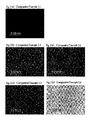
- the polymerizable compound-containing liquid crystal compositions of Examples 2-1, 2-2, 2-3, 2-8, 2-9, 2-10, 2-11, and 2-12 and Comparative Examples 2-1, 2-2, 2-3, and 2-6 and the polymerizable compound-free liquid crystal composition of Comparative Example 1-1 were evaluated for alignment properties in the same manner as in Example 1-1. The results of evaluation are shown in Table 4. Polarizing micrographs of the samples between crossed polarizers are shown in Figs. 1 and 2 .
- the polymerizable compound-containing liquid crystal compositions of Comparative Examples 2-1, 2-2, 2-3, and 2-6 were rated AA to B in Comparative Example 2.
- polymerizable compound No. 1 One part of polymerizable compound No. 1 was mixed with 99 parts of each of liquid crystal composition Nos. 2 to 4, and a photopolymerization initiator, Irgacure 651 from Ciba Specialty Chemicals, was added to the mixture in an amount of 2% based on the polymerizable compound to give a polymerizable compound-containing liquid crystal composition.
- a photopolymerization initiator Irgacure 651 from Ciba Specialty Chemicals
- Example 6 The response time of the polymerizable compound-containing liquid crystal compositions of Examples 2-1, 2-2, and 2-3 was measured in the same manner as in Example 1-1. The results obtained are shown in Table 6. Table 6 also contains the result of the polymerizable compound-free liquid crystal composition No.1 measured in Comparative Example 1-1.
- the polymerizable compound-containing liquid crystal compositions of Example 2-1 and 2-2 were evaluated for polymerization reactivity.
- a test cell for liquid crystal evaluation (cell gap: 5 ⁇ m; electrode area: 8 mm x 8 mm; alignment film: JALS 2096) was filled with the liquid crystal composition, sealed the inlet with a sealant, and irradiated with light of 1000 mJ/cm 2 using a high pressure mercury lamp to induce photopolymerization. Then, the cell was disassembled, and the polymerized liquid crystal composition in the cell was extracted with acetonitrile. The extract was analyzed by HPLC. Separately, the same liquid crystal compositions before polymerization were analyzed by HPLC. The peak intensity of the residual monomer in HPLC after polymerization and that before polymerization were compared to calculate a monomer retention (%). The results obtained are shown in Table 7 below.
- VHR was measured in the same manner as in Example 1-1, except that the measuring temperature was changed to 60°C, and the results were compared with those of Evaluation Example 2, which were obtained at a measuring temperature of 25°C.
- the results obtained are shown in Table 5.
- polymerizable compound No. 1 in which M 1 and M 2 are both methyl, is not so different from other polymerizable compounds in VHR at a measuring temperature of 25°C but shows a smaller reduction in VHR at a measuring temperature of 60°C from VHR at 25°C than the other polymerizable compounds.
- liquid crystal compositions of the invention have good solubility and, upon being irradiated with an energy ray, such as an ultraviolet ray, provide an LCD capable of high-speed response without undergoing reduction in reliability (voltage holding ratio).
- an energy ray such as an ultraviolet ray
- the liquid crystal composition of the invention is useful in that it does not undergo reduction in VHR when irradiated with an energy ray, such as an ultraviolet ray, and provides an LCD capable of high-speed response.
- an energy ray such as an ultraviolet ray
Abstract

Description
- This invention relates to a liquid crystal composition having a specific liquid crystal composition and a polymerizable liquid crystal compound having a (meth)acryloyl group as a polymerizable group and an electrooptical display device having the liquid crystal composition sandwiched between substrates.
- A large number of liquid crystal displays (LCDs) utilizing optical (refractive index) anisotropy (Δn) (hereinafter sometimes simply referred to as Δn) and dielectric anisotropy (Δε) (hereinafter sometimes simply referred to as Δε) characteristic of liquid crystal compounds have been produced. LCDs are widely applied to watches, calculators, various measuring instruments, automotive panels, word processors, electronic notebooks, cell phones, printers, computers, TV sets, etc. and in ever increasing demand. A liquid crystal compound exhibits an inherent liquid crystal phase between a solid phase and a liquid phase. Liquid crystal phases are roughly classified into a nematic phase, a smectic phase, and a cholesteric phase. For display applications, a nematic phase is most widely used. Display modes applied to LCDs typically include twist nematic (TN), super twist nematic (STN), dynamic scatter (DS), guest host (GH), in-plane switching (IPS), optically compensated birefringence (OCB), electrically controlled birefringence (ECB), vertical alignment (VA), color super homeotropic (CSH), and ferroelectric liquid crystal (FLC). As drive systems, a multiplex drive system has now become common, replacing a traditional static drive system. Passive matrix LCDs and, more lately, active matrix (AM) LCDs driven by thin film transistors (TFTs) or MIMs are prevailing.
- Conventional AM-LCDs mostly use a TN mode liquid crystal cell in which molecules of a liquid crystal material having a positive dielectric anisotropy (Δε) are aligned to be in parallel to the substrates and twisted by 90 degrees between the opposing substrates. However, the TN mode LCDs have a disadvantage of a narrow viewing angle, and various studies have been made to increase the viewing angle.
- VA mode LCDs, particularly MVA and EVA mode LCDs described in non-patent documents 1 and 2 (see below) have been developed as an alternative to TN mode LCDs and succeeded in greatly improving viewing angle characteristics. In these VA mode LCDs, molecules of a liquid crystal material having negative dielectric anisotropy between two substrate are aligned perpendicular to the substrates and, with a voltage applied, the tilt direction of the liquid crystal directors are controlled by ribs or slits made on the surface of the substrates. Recently, an LCD made by using a liquid crystal material containing a monomer or an oligomer polymerizable on light or heat application has been proposed as in patent document 1 (see below). An LCD of this type is produced by sealing the liquid crystal material in between two substrates and polymerizing the polymerizable component while adjusting the voltage applied to the liquid crystal layer thereby to decide the alignment direction of the liquid crystal molecules.
- Thus studies to improve the viewing angle characteristics are well underway, providing practical big LCD panels for notebook or desktop computers and even bigger display media represented by LCD-TV monitors. However, there is a problem with these LCDs that they are slow in response to an electric field, and demands for rapid response are still high. LCDs used to display moving images, such as LCD-TVs, are particularly required to exhibit a rapid response. In order to achieve high definition and high display qualities with an LCD, it is necessary to develop and use a liquid crystal material having rapid response characteristics.
- In order to obtain a good contrast ratio with an LCD driven at a constant frame rate, it is desirable for the LCD to have a high voltage holding ratio (voltage holding ratio during a frame period, hereinafter abbreviated as VHR). In the case where a liquid crystal material is given energy, such as light or heat, as in patent document 1, the compound can deteriorate to cause reduction in VHR.
- Patent document 1 discloses a VA mode LCD with reduced burn-in and a composition used therefor. Patent document 2 below discloses an alignment film providing a VA mode LCD having a high VHR. With these techniques, nevertheless, a satisfactory response speed is not obtained. Patent documents 3 and 4 below disclose a VA mode liquid crystal composition but have no mention of the use of a polymerizable liquid crystal compound having a (meth)acryloyl group as a polymerizable group. Patent document 5 below proposes a polymerizable liquid crystal compound but neither describes nor suggests the use of the compound in a liquid crystal composition having negative dielectric anisotropy (Δε).
-
- Patent document 1:
JP 2003-307720A - Patent document 2:
JP 2006-215184A - Patent document 3:
JP 2005-48007A - Patent document 4:
JP 2007-23071A - Patent document 5:
JP 2007-119415A - Non-patent document 1: EKISHO, vol. 3, No. 1, p. 117 (1999)
- Non-patent document 2: EKISHO, vol. 3, No. 4, p. 272 (1999)
- An object of the invention is to provide a liquid crystal composition that does not deteriorate in reliability (VHR) on being irradiated with energy rays, such as ultraviolet rays, and affords an LCD capable of high speed response.
- The above object of the invention is accomplished by the provision of a liquid crystal composition comprising 100 parts by mass of a nematic liquid crystal composition having negative dielectric anisotropy (Δε) and 0.01 to 3 parts by mass of a polymerizable compound represented by general formula (I):
-

M1 and M2 each independently represent a hydrogen atom or a methyl group;
Z1 represents a direct bond, -L1-, -L1O-, -L1O-CO-, or -L1CO-O-, and Z4 represents a direct bond, -L2-, -OL2-, -O-COL2-, or -CO-OL2-, provided that at least one of Z1 and Z4 is not a direct bond; wherein L1 and L2 each independently represent an optionally branched alkylene group having 1 to 10 carbon atoms, the alkylene group being optionally interrupted by one to three oxygen atoms, provided that the two or three interrupting oxygen atoms are not continuous and that the interrupting oxygen atom is not continuous to an oxygen atom adjacent to the alkylene group; when Z1 and Z4 are the same, one or more hydrogen atoms of the rings C1, C2, and C3 are substituted by an alkyl group having 1 to 3 carbon atoms, an alkoxy group having 1 to 3 carbon atoms, an acyl group having 1 to 3 carbon atoms, or a halogen atom;
Z2 and Z3 each independently represent a direct bond, an ester bond, an ether bond, or an optionally branched, saturated or unsaturated alkylene group having 2 to 8 carbon atoms, or a combination thereof; and
p and q each independently represent 0 or 1, provided that p+q≥1. - The invention also provides an electrooptical display device fabricated by sandwiching the liquid crystal composition of the invention between two substrates at least one of which has an electrode to apply a voltage to liquid crystal molecules, irradiating the liquid crystal composition with an energy ray to cause the polymerizable compound represented by general formula (I) present in the liquid crystal composition to polymerize.
-
-
Fig. 1(a), Fig. 1(b), Fig. 1(c), Fig. 1(d), Fig. 1(e), Fig. 1(f), Fig. 1(g), and Fig. 1(h) each present a polarizing micrograph of a liquid crystal composition of the invention observed in Evaluation Example 1, of whichFig. 1(a) is a polarizing micrograph of the liquid crystal composition of Example 2-1;Fig. 1(b) , of Example 2-2;Fig. 1(c) , of Example 2-3;Fig. 1(d) , of Example 2-8;Fig. 1(e) , of Example 2-9;Fig. 1(f) , of Example 2-10;Fig. 1(g) , of Example 2-11; andFig. 1(h) , of Example 2-11. -
Fig. 2(a), Fig. 2(b), Fig. 2(c), Fig. 2(d), and Fig. 2(e) each present a polarizing micrograph of a comparative liquid crystal composition observed in Evaluation Example 1, of whichFig. 2(a) is a polarizing micrograph of the liquid crystal composition of Comparative Example 1-1;Fig. 2(b) , of Comparative Example 2-1;Fig. 2(c) , of Comparative Example 2-2;Fig. 2(d) , of Comparative Example 2-3; andFig. 2(e) , of Comparative Example 2-6. - The present invention will be described in detail based on its preferred embodiments.
- The liquid crystal composition of the invention comprises 100 parts by mass of a nematic liquid crystal composition having negative dielectric anisotropy (Δε) and 0.01 to 3 parts by mass of a polymerizable compound represented by general formula (I). The liquid crystal composition preferably contains 0.05 to 2 parts by mass of the polymerizable compound per 100 parts by mass of the nematic liquid crystal composition. If the content of the polymerizable compound is less than 0.01 parts by mass, the response is slow. If it is more than 3 parts by mass, the composition has poor solubility. More preferably, the content of the polymerizable compound is from 0.05 to 1 part by mass per 100 pats by mass of the nematic liquid crystal composition. With this content the composition achieves a particularly high VHR.
- Examples of the C1-C3 alkyl group, the C1-C3 alkoxy group, and the C1-C3 acyl group that may be substituted for the hydrogen atom of the rings C1, C2, and C3 in formula (I) include methyl, ethyl, propyl, and isopropyl; methoxy, ethoxy, propoxy, and isopropoxy; and formyl, acetyl, and propionyl, respectively. Examples of the halogen atom that may be substituted for the hydrogen atom of the rings C1, C2, and C3 in formula (I) include fluorine, chloride, bromine, and iodine.
- Examples of the optionally branched C1-C10 alkylene group represented by L1 and L2 in formula (I) include methylene, ethylene, propylene, trimethylene, tetramethylene, butane-1,3-diyl, 2-methylpropane-1,3-diyl, 2-methylbutane-1,3-diyl, pentane-2,4-diyl, pentane-1,4-diyl, 3-methylbutane-1,4-diyl, 2-methylpentane-1,4-diyl, pentamethylene, hexamethylene, heptamethylene, octamethylene, nonamethylene, and decamethylene.
- Examples of the direct bond, the ester bond, the ether bond, the optionally branched, saturated or unsaturated C2-C8 alkylene group, or a combination thereof include -CO-O-, -O-CO-, -O-CO-O-, -(CH2)a-, -(CH2)a-O-, -O-(CH2)a-, -O-(CH2)a-O-, -(CH2)a-O-CO-, -CO-O-(CH2)a-, -(CH2)a-CO-O-, -O-CO-(CH2)a-, -(CH2)a-O-CO-O-, -O-CO-O-(CH2)a-, -O-(CH2)a-O-CO-, -CO-O-(CH2)2-O-, -O-(CH2)a-CO-O-, -O-CO-(CH2)a-O-, -O-(CH2)a-O-CO-O-, -O-CO-O-(CH2)a-O-, -(CH2CH2O)b-, and -(OCH2CH2)b-, wherein a is an integer of 2 to 8, and b is an integer of 1 to 3.
- The compound of formula (I) in which at least one hydrogen atom of the rings C1, C2, and C3 is substituted by C1-C3 alkyl, C1-C3 alkoxy, C1-C3 acyl, or halogen is preferred as having good solubility in the nematic liquid crystal compound. As used therein, the expression "when Z1 and Z4 are the same" means that Z1 and Z4 are a combination of -L1- and -L2-, a combination of -L1O- and -OL2-, a combination of -L1O-CO- and -CO-OL2-, or a combination of -L1CO-O- and -O-COL2-.
- The compound of formula (I) in which Z1 and Z4 are different or L1 and L2 are different; the compound of formula (I) in which either Z1 or Z4 is a direct bond; the compound of formula (I) in which Z2 and Z3 are each an ester bond; and the compound of formula (I) in which L1 and/or L2 (especially L1 and L2) is/are a C2-C8 alkylene group are also preferred for their good solubility in the nematic liquid crystal composition.
- In preparing the liquid crystal composition of the invention, it is advisable that the polymerizable compound of formula (I) be dissolved in the nematic liquid crystal composition at room temperature because heating the system for facilitating dissolving can invite reduction in VHR. From this point of view, it is preferred for the polymerizable compound to be used to have good solubility.
- The polymerizable compounds of formula (I) in which p and q are both 1; the polymerizable compounds of formula (I) in which either M1 or M2 is methyl; and the polymerizable compounds of formula (I) in which M1 and M2 are both methyl are still preferred in terms of superior reliability of the resulting liquid crystal compositions. Those in which M1 and M2 are both methyl are particularly preferred for their high polymerization reactivity.
- Examples of the polymerizable compound of general formula (I) include, but are not limited to, the following compounds.
-


-


-


-


-


-


- The nematic liquid crystal composition having negative dielectric anisotropy (Δε) that can be used in the invention may be prepared using any appropriate known liquid crystal compound so as to exhibit negative dielectric anisotropy (Δε). In particular, a nematic liquid crystal composition containing a liquid crystal compound represented by general formula (II) shown below in a proportion of 30 to 100% by mass is preferred for its excellent liquid crystal display characteristics. The liquid crystal compounds represented by formula (II) may be used either individually or as a combination of two or more thereof.
-

R3 and R4 each independently represent an alkyl group having 1 to 6 carbon atoms or an alkenyl group having 2 to 6 carbon atoms;
j, k, and m each independently represent 0 or 1, provided that j+k+m≥1; and
n represents 0 or 1. - Examples of the C1-C3 alkyl group and the C1-C3 alkoxy group that may be substituted for the hydrogen atom of the rings B1, B2, B3, and B4 in formula (II) include those enumerated above for the C1-C3 alkyl group and the C1-C3 alkoxy group that may be substituted for the hydrogen atom of the rings C1, C2, and C3 in formula (I).
- Examples of the C1-C6 alkyl group represented by R3 and R4 in formula (II) include methyl, ethyl, propyl, isopropyl, butyl, s-butyl, t-butyl, isobutyl, amyl, isoamyl, t-amyl, hexyl, 2-hexyl, and 3-hexyl. Examples of the C2-C6 alkenyl group represented by R3 and R4 in formula (II) include vinyl, 1-methylethenyl, 2-methylethenyl, 2-propenyl, 1-methyl-3-propenyl, 3-butenyl, 1-methyl-3-butenyl, isobutenyl, 3-pentenyl, and 4-hexenyl.
- Of the liquid crystal compounds of general formula (II), preferred is the one represented by general formula (III), for the nematic liquid crystal composition containing the compound of formula (III) provides particularly excellent liquid crystal display characteristics.
-


- Of the liquid crystal compounds of formula (III), preferred is the one in which E1, E2, E3, and E4 are each hydrogen or fluorine, namely the one in which one of the E1/E2 combination and the E3/E4 combination consists solely of fluorine atoms with the other consisting solely of hydrogen atoms or the one in which both the combinations consist solely of fluorine atoms, for the nematic liquid crystal composition containing this compound provides further improved display characteristics, such as response time, and reliability.
- Examples of the compound represented by formula (II) include, but are not limited to, the following compounds. In formulae shown below, R13 is C2-C5 alkyl, and R14 is C1-C5 alkyl.
-

-


-


-


- The following compounds are particularly preferred among the compounds shown above.
-


- It is more preferred that the nematic liquid crystal composition having negative dielectric anisotropy (Δε) further contain a liquid crystal compound represented by general formula (IV) shown below for providing further improved liquid crystal display characteristics. The content of the compound of formula (IV) is preferably 5% to 50% by mass, more preferably 10% to 50% by mass. When used in an amount less than 5%, the compound produces insufficient effects of use. Use of more than 50% of the compound tends to result in a reduction in VHR.
-


X1, and X2 each independently represent a direct bond, -CH2-CH2-, -CF2-CF2-, -CH=CH-, -CF=CF-, -CH2-O-, -O-CH2-, -CF2-O-, -O-CF2-, or -C≡C-;
R1 and R2 each independently represent an alkyl group having 1 to 6 carbon atoms or an alkenyl group having 2 to 6 carbon atoms; and
g and h each independently represent 0 or 1. - Examples of the C1-C3 alkyl group and the C1-C3 alkoxy group that may be substituted for the hydrogen atom of the rings A1, A2, and A3 in formula (IV) include those enumerated above for the C1-C3 alkyl group and the C1-C3 alkoxy group that may be substituted for the hydrogen atom of the rings C1, C2, and C3 in formula (I).
- Examples of the C1-C6 alkyl group and the C2-C6 alkenyl group represented by R1 and R2 in formula (IV) include those recited above for the C1-C6 alkyl group and the C2-C6 alkenyl group represented by R3 and R4 in formula (II).
- Examples of the compound represented by formula (IV) include, but are not limited to, the following compounds.
-


- The following compounds are particularly preferred among the compounds shown above.
-


- The nematic liquid crystal composition for use in the liquid crystal composition of the invention may further contain other commonly used liquid crystal compounds within a range that secures negative dielectric anisotropy (Δε). Examples of such liquid crystal compounds include, but are not limited to, the following compounds. In chemical formulae below, W1 is hydrogen or an optionally branched alkyl, alkoxy, alkenyl, alkenyloxy, alkynyl, alkynyloxy, alkoxyalkyl, alkanoyloxy, or alkoxycarbonyl group having 1 to 8 carbon atoms, each optionally being substituted with a halogen atom, a cyano group, etc.; W2 is cyano, halogen, or a group represented by W1; and W3, W4, and W5 are each hydrogen, halogen, or cyano, provided that the compounds corresponding to the general formulae (II) and (IV) are excluded.
-

-

-

- The liquid crystal composition of the invention may contain a photopolymerization initiator. The photopolymerization initiator for use in the invention may be any known compound, including benzoin ethers, such as benzoin butyl ether; benzyl ketals, such as benzyl dimethyl ketal; α-hydroxyacetophenones, such as 1-hydroxy-1-benzoylcyclohexane, 2-hydroxy-2-benzoylpropane, and 2-hydroxy-2-(4'-isopropyl)benzoylpropane; chloroaceto phenones, such as 4-butylbenzoyltrichloromethane and 4-phenoxybenzoyldichloromethane; α-aminoacetophenones, such as 1-benzyl-1-dimethylamino-1-(4'-morpholinobenzoyl) propane, 2-morpholyl-2-(4'-methylmercapto)benzoylpropane, 9-n-butyl-3,6-bis(2'-morpholinoisobutyroyl)carbazole, and 2-methyl-1-[4-(methylthio)phenyl]-2-morpholino propan-1-one; acylphosphine oxides, such as bis(2,4,6-trimethylbenzoyl)-phenylphosphine oxide; α-dicarbonyls, such as benzil and methylbenzoyl formate; triazines, such as p-methoxyphenyl-2,4-bis(trichloromethyl)-s-triazine, 2-methyl-4,6-bis(trichloromethyl) -s-triazine, 2-phenyl-4,6-bis(trichloromethyl)-s-triazine, 2-naphthyl-4,6-bis(trichloromethyl) -s-triazine, and 2-(p-butoxystyryl)-s-triazine; α-acyloxime esters, such as those described in
JP 2000-80068A JP 2001-233842A JP 2005-97141A JP 2006-516246A 3860170 3798008 WO2006/018973 ; benzoyl peroxide, 2,2'-azobisisobutyronitrile, ethylanthraquinone, 1,7-bis(9'-acridinyl)heptane, thioxanthone, 1-chloro-4-propoxy thioxanthone, isopropylthioxanthone, diethylthioxanthone, benzophenone, phenyl biphenyl ketone, 4-benzoyl-4'-methyldiphenyl sulfide, 2-(p-butoxystyryl)-5-trichloromethyl-1,3,4-oxadiazole, 9-phenylacridine, 9,10-dimethylbenzphenazine, benzophenone/Michler's ketone, hexaarylbiimidazole/mercaptobenzimidazole, and thioxanthone/amine. Inter alia, benzoin ethers, benzyl ketals, α-hydroxyacetophenones, and α-aminoacetophenones are preferred. - A combination of the photopolymerization initiator and a sensitizer is also preferably used. Examples of useful sensitizers are thioxanthone, phenothiazine, chlorothioxanthone, xanthone, anthracene, dipyhenylanthracene, and rubrene.
The total amount of the photopolymerization initiator and/or the sensitizer, if added, is preferably 10 parts by mass or less, more preferably 5 parts by mass or less, even more preferably 0.1 to 3 parts by mass, per 100 parts by mass of the polymerizable compound of formula (I). - Additives may be added to the liquid crystal composition of the invention where needed to improve characteristics of the polymerizable composition, including functional compounds, such as storage stabilizers, antioxidants, ultraviolet absorbers, infrared absorbers, fine particles of organic, inorganic or other materials, and polymers.
- The storage stabilizers serve to improve storage stability of the liquid crystal composition, including hydroquinone, hydroquinone monoalkyl ethers, tert-butyl catechols, pyrogallols, thiophenols, nitro compounds, 2-naphtylamines, and 2-hydroxynaphthalenes. The amount of the storage stabilizer, if used, is preferably 1 part by mass or less, more preferably 0.5 parts by mass or less, per 100 parts by mass of the polymerizable compound.
- Any known antioxidants may be used, including hydroquinone, 2,6-di(tert-butyl)-p-cresol, 2,6-di(tert-butyl)phenol, triphenyl phosphite, and trialkyl phosphites.
- Any known UV absorbers may be used, including salicylic ester compounds, benzophenol compounds, benzotriazole compounds, triazine compounds, cyanoacrylate compounds, and nickel complex salt compounds.
- The above mentioned additives may be used appropriately with no particular limitation as long as the characteristics of the resulting polymer are not impaired. Preferably, the total amount of these optional components is not more than 30 parts by mass, more preferably 10 parts by mass or less, per 100 parts by mass of the sum of the nematic liquid crystal compound having negative dielectric anisotropy (Δε) and the polymerizable compound represented by the general formula (I).
- The liquid crystal composition of the invention is used by polymerizing the polymerizable compound by known processes using light, electromagnetic radiation, or heat. Examples of the preferred light include ultraviolet light, visible light, and infrared light. Electromagnetic radiation, such as electron beams and X rays, may also be used. Usually, ultraviolet light or visible light is preferred. A preferred wavelength range is from 150 to 500 nm, more preferably from 250 to 450 nm, even more preferably 300 to 400 nm. Light sources include low pressure mercury lamps (e.g., bactericidal lamps, fluorescent chemical lamps, and black lights), high pressure discharge lamps (e.g., high pressure mercury lamps and metal halide lamps), and short arc discharge lamps (ultrahigh pressure mercury lamps, xenon lamps, and mercury xenon lamps), with high pressure mercury lamps and ultrahigh pressure mercury lamps being preferred. The liquid crystal composition may be irradiated with the light as emitted from a light source or a light ray of a specific wavelength or light rays of a specific wavelength range selected through a filter. A preferred irradiation energy density is 10 to 50000 mJ/cm2, more preferably 10 to 20000 mJ/cm2. A preferred illuminance is 0.1 to 5000 mW/cm2, more preferably 1 to 2000 mW/cm2. With a small amount of exposure, the polymerization is insufficient. Too large an amount of exposure can result in a reduction in VHR.
- The electrooptical display device of the present invention is then described. The electrooptical display device of the invention is produced by sandwiching the liquid crystal composition of the invention between two substrates at least one of which has an electrode for applying a voltage to liquid crystal molecules, irradiating the liquid crystal composition with an energy ray, such as an ultraviolet ray, to cause the polymerizable compound represented by general formula (I) to polymerize.
- The substrate may be selected as appropriate to the intended driving system and display system from those conventionally used in electrooptical display devices with no particularly restrictions. Examples of the energy ray include the above described light, electromagnetic radiation, and heat as well as an ultraviolet ray.
- The electrooptical display device of the invention may be of AM drive type or passive matrix (PM) drive type. An LCD driven in an AM or PM scheme is applicable to any of reflective, transmissive, and semi-transmissive LCDs.
- The electrooptical display device of the invention is also useful as a dynamic scattering (DS) mode device using a liquid crystal composition containing an electroconductive agent, a nematic curvilinear aligned phase (NCAP) device prepared by microencapsulating a liquid crystal composition, and a polymer dispersed (PD) device using a liquid crystal composition having a three dimensional network polymer structure, for example, a polymer network (PN) device.
- Having the aforementioned characteristics, the liquid crystal composition of the invention is particularly suited for use in AM LCDs having a display mode utilizing a negative dielectric anisotropy, such as a VA mode and an IPS mode, especially AM LCDs having a VA display mode.
- In VA mode LCDs, the direction of the electric field applied is perpendicular to the liquid crystal layer, while in IPS mode LCDs, the direction of the electric field is in parallel to the liquid crystal layer. The structure of VA mode LCDs is reported, e.g., in K. Ohmuro, S. Kataoka, T. Sasaki and Y. Koike, SID '97 Digest of Technical Papers, vol. 28, p. 845 (1997), and the structure of IPS mode LCDs is reported, e.g., in
WO91/10936 U.S. Pat. No. 5,576,867 ). - The electrooptical display devices having the liquid crystal composition of the invention are applicable to watches, calculators, measuring instruments, automotive panels, copiers, cameras, business machines, PDAs, notebook or desktop computer monitors, TV monitors, cell phones, light control glass, optical shutters, and replacement polarizers. The characteristics of the electrooptical display devices of the invention are particularly taken advantage of in applications to large PDAs, notebook or desktop computer monitors, and TV monitors.
- The present invention will now be illustrated in greater detail with reference to Examples, but it should be understood that the invention is not deemed to be limited thereto. Unless otherwise noted, all the parts and percents given below are by mass.
- Nematic liquid crystal compositions having negative Δε for use in the invention were prepared in Reference Example. Polymerizable compounds of the invention and comparative polymerizable compounds were synthesized in Synthesis Examples.
In Examples 1 and Comparative Examples 1, liquid crystal compositions containing a varied amount of a polymerizable compound of the invention were prepared and compared as to various characteristics.
In Examples 2 and Comparative Examples 2, a polymerizable compound of the invention or a comparative polymerizable compound was compounded into a nematic liquid crystal composition for use in the invention to prepare polymerizable compound-containing liquid crystal compositions (hereinafter also referred to as polymerizable liquid crystal compositions), which were compared as to solubility, and the alignment properties of these polymerizable liquid crystal compositions were evaluated in Evaluation Example 1.
In Examples 3, liquid crystal compositions of the invention were prepared using nematic liquid crystal compositions having different formulations. The liquid crystal compositions prepared in Examples 2 and 3 were evaluated for VHR in Evaluation Example 2.
The response time of the polymerizable liquid crystal compositions of Examples 2 was measured in Evaluation Example 3.
The polymerizable liquid crystal compositions of Examples 2 were compared in terms of polymerization reactivity in Evaluation Example 4.
The polymerizable liquid crystal compositions of Examples 2 were compared as to VHR as measured at varied temperatures in Evaluation Example 5. - Liquid crystal composition Nos. 1 to 4 were prepared using liquid crystal compound Nos. 1 to 16 according to the formulations shown in Table 1. Liquid crystal compound Nos. 1 to 7 correspond to general formula (IV), liquid crystal compound Nos. 8 to 13 correspond to general formula (II), and liquid crystal compound Nos. 14 to 16 are other liquid crystal compounds.
-


-


-


-

- Polymerizable compound No. 1 was synthesized in accordance with steps 1 to 3 described below.
- A benzyl ether compound was synthesized as follows according to reaction scheme 1:
-

- In 40 g of THF was dissolved 7.00 g (27.32 mmol) of 6-methacryloyloxy-2-naphthoic acid After cooling the solution to -30°C, 4.69 g (40.97 mmol) of methanesulfonyl chloride was added thereto, and 8.57 g (84.68 mmol) of triethylamine (TEA) was added thereto dropwise, followed by stirring for 1 hour. To the mixture was added 33 mg (0.27 mmol) of 4-dimethylaminopyridine (DMAP), and a solution of 6.95 g (28.68 mmol) of 4-benzyloxy-2-n-propylphenol in 15 g of THF was added thereto dropwise, followed by stirring for 1 hour. The reaction mixture was washed with water, and the solvent was removed by evaporation. The residue was purified by column chromatography on SiO2 (developing solvent: dichloromethane). Recrystallization from acetone gave 6.40 g of the benzyl ether compound as a white solid in a yield of 48.7%.
- A phenol compound was synthesized from the benzyl ether compound obtained in step 1 in accordance with reaction scheme:
-

- In 20 g of anisole was dissolved 5.3 g (40.0 mmol) of anhydrous aluminum chloride. A solution of 6.40 g (13.3 mmol) of the benzyl ether compound obtained in step 1 in 20 g of anisole was dropwise added to the solution while cooling with ice-water, followed by stirring for 1 hour. After the reaction system was allowed to warm to room temperature, hydrochloric acid was added thereto dropwise to dissolve the precipitate. The reaction mixture was washed with water, and the solvent was removed by evaporation. The residue was purified by column chromatography on SiO2 (developing solvent: ethyl acetate/toluene). Recrystallization from an acetone/methanol mixed solvent gave 3.62 g of the phenol compound as white crystals in a yield of 69.7%.
- Polymerizable compound No. 1 was synthesized using the phenol compound obtained in step 2 as follows in accordance with reaction scheme 3:
-

- In 8 g of THF was dissolved 1.87 g (6.10 mmol) of 4-(6-methacryloxy-hexyloxy)-benzoic acid, and the solution was cooled to -30°C. To the solution was added 0.77 g (6.71 mmol) of methanesulfonyl chloride, and 1.48 g (14.6 mmol) of triethylamine was then added thereto dropwise. After stirring for 1 hour, 7 mg (0.06 mmol) of DMAP was added, and a solution of 2.5 g (6.40 mmol) of the phenol compound obtained in step 2 in 10 g of THF was added thereto dropwise, followed by stirring for 1 hour. The reaction mixture was washed with water, and the solvent was removed by evaporation. The residue was purified by column chromatography on SiO2 (developing solvent: ethyl acetate/toluene). Recrystallization from an ethyl acetate-hexane mixed solvent afforded 1.45 g of polymerizable compound No. 1 as a white solid in a yield of 35.0%. The analytical results of the resulting polymerizable compound No. 1 are shown below.
- Analytical results:
- IR (KBr), cm-1:
2952, 2870, 1736, 1710, 1634, 1606, 1511, 1491, 1474, 1279, 1257, 1186, 1170, 1150, 1133, 1112, 1083, 1069, 910, 764, 480 - 1H-NMR (CDCl3), ppm:
0.9(t;3H), 1.5-1.9(m;10H), 2.0(s;3H), 2.1(s;3H), 2.6(q;2H), 4.1(t;2H), 4.2(t;2H), 5.6(s;1H), 5.8(s;1H), 6.1(s;1H), 6.5(s;1H), 7.0-7.4(m;6H), 7.7-8.3(m;6H), 8.8(s;1H) - Polymerizable compound No. 1 obtained was analyzed on a differential scanning calorimeter (DSC 7 from Perkin Elmer) under conditions of a nitrogen atmosphere of 50 ml/min, a heating rate of 5°C/min, and a heating temperature of from 25°C up to 180°C. As a result, the compound exhibited the phase transition behavior shown below. The liquid crystal phase was identified by observing a sample sandwiched between glass plates and heated on a hot stage under a polarizing microscope.
-

- Polymerizable compound Nos. 2 to 7, 11, and 41 to 44 and comparative polymerizable compound Nos. 3 to 8 in comparative polymerizable compounds shown below were synthesized in accordance with the procedures used to prepare polymerizable compound No. 1 or any known synthesis procedures.
-


- Examples and Comparative Examples which follow were carried out using liquid crystal composition Nos. 1 through 4 obtained in Reference Example, polymerizable compound Nos. 1 through 7, 11, and 41 to 44, comparative polymerizable compound Nos. 3 to 8, which were prepared in Synthesis Examples, and comparative polymerizable compound Nos. 1 and 2, which are commercially available. Comparative polymerizable compound No. 1 is KS-HDDA from Nippon Kayaku Co., Ltd. Comparative polymerizable compound No. 2 is DCP-A from Kyoeisha Chemical Co., Ltd.
- Polymerizable compound No. 1 was mixed with liquid crystal composition No. 1 in the amount shown in Table 2 per 100 parts of the composition. Irgacure 651 from Ciba Specialty Chemicals Corp. was added thereto as a photopolymerization initiator in an amount of 2% with respect to the polymerizable compound to provide a polymerizable compound-containing liquid crystal composition. In Comparative Example 1-1, either a polymerizable compound or a photopolymerizable initiator was not added to liquid crystal composition No. 1.
The resulting polymerizable compound-containing liquid crystal compositions were evaluated for solubility, alignment properties, VHR, and response time in accordance with the following methods of measurement or evaluation. - The solubility of the polymerizable liquid crystal compositions was examined. A composition that dissolved at room temperature was rated "AA". A composition that dissolved on heating was rated "A". A composition that dissolved upon heating but crystallized out when left to stand at room temperature for one day was rated "B". A composition that did not completely dissolve even under heating was rated "C".
- A test cell for liquid crystal evaluation (cell gap: 5 µm; electrode area: 8 mm x 8 mm; alignment film: JALS 2096) was filled with each of the polymerizable liquid crystal compositions, sealed the inlet with a sealant, and irradiated with light of 1000 mJ/cm2 using a high pressure mercury lamp to make a sample. The sample was observed with the naked eye under a polarizing microscope (between crossed polarizers, with voltage off). A sample showing good alignment was rated "good". A sample showing disturbed alignment was rated "no good".
- The sample prepared in (2) above was subjected to VHR measurement using VHR-A1 available from Toyo Corp. under conditions of a voltage pulse width of 60 µs, a frame time of 16.7 ms, an amplitude of ±5 V, and a measuring temperature of 25°C.
- The sample prepared in (2) above was subjected to response time measurement using LCD-5100 from Otsuka Electronics Co., Ltd. at a measuring temperature of 25°C.
- The results of evaluation and measurement are shown in Table 2.
-
Table 2 Polymerizable Compound No. 1 (part) Solubility Alignment Properties VHR (%) Response Time (ms) Comparative Example 1-1 0 - good 99.3 53 Example 1-1 0.05 AA good 99.3 47 Example 1-2 0.1 AA good 99.3 46 Example 1-3 0.3 AA good 99.3 44 Example 1-4 0.5 AA good 99.3 44 Example 1-5 0.8 AA good 99.3 44 Example 1-6 1 AA good 99.3 41 Example 1-7 2 AA good 99.1 39 Comparative Example 1-2 5 A good 98.9 79 Comparative Example 1-3 10 C - - - - As is apparent from the results in Table 2, adding more than 3 parts of the polymerizable compound per 100 parts of the liquid crystal composition causes a large reduction in response speed and a reduction in solubility. It is also seen that the response is slow in the absence of the polymerizable compound.
- One part of each of polymerizable compound Nos. 1 to 7, 11, and 41 to 44 and comparative polymerizable compound Nos. 1 to 8 and 99 parts of liquid crystal composition No. 1 were compounded, and Irgacure 651 from Ciba Specialty Chemicals Corp. was added thereto as a photopolymerization initiator in an amount of 2% with respect to the polymerizable compound to provide a polymerizable compound-containing liquid crystal composition.
The solubility of the resulting polymerizable liquid crystal compositions was examined. A composition that dissolved at room temperature was rated "AA". A composition that dissolved on heating was rated "A". A composition that dissolved upon heating but crystallized out when left to stand at room temperature for one day was rated "B". A composition that did not completely dissolve even under heating was rated "C". The results of evaluation are shown in Table 3. -
Table 3 Liquid Crystal Composition Polymerizable Compound Solubility Example 2-1 Liquid Crystal Composition No. 1 Polymerizable Compound No.1 AA Example 2-2 Liquid Crystal Composition No. 1 Polymerizable Compound No.2 AA Example 2-3 Liquid Crystal Composition No. 1 Polymerizable Compound No.3 AA Example 2-4 Liquid Crystal Composition No. 1 Polymerizable Compound No.4 AA Example 2-5 Liquid Crystal Composition No. 1 Polymerizable Compound No.5 AA Example 2-6 Liquid Crystal Composition No. 1 Polymerizable Compound No.6 AA Example 2-7 Liquid Crystal Composition No. 1 Polymerizable Compound No.7 AA Example 2-8 Liquid Crystal Composition No. 1 Polymerizable Compound No.11 AA Example 2-9 Liquid Crystal Composition No. 1 Polymerizable Compound No.41 A Example 2-10 Liquid Crystal Composition No. 1 Polymerizable Compound No.42 A Example 2-11 Liquid Crystal Composition No. 1 Polymerizable Compound No.43 A Example 2-12 Liquid Crystal Composition No. 1 Polymerizable Compound No.44 A Comp. Ex.2-1 Liquid Crystal Composition No. 1 Comp. Polymerizable Compound No.1 AA Comp. Ex.2-2 Liquid Crystal Composition No. 1 Comp. Polymerizable Compound No.2 AA Comp. Ex.2-3 Liquid Crystal Composition No. 1 Comp. Polymerizable Compound No.3 A Comp. Ex.2-4 Liquid Crystal Composition No. 1 Comp. Polymerizable Compound No.4 C Comp. Ex.2-5 Liquid Crystal Composition No. 1 Comp. Polymerizable Compound No.5 C Comp. Ex.2-6 Liquid Crystal Composition No. 1 Comp. Polymerizable Compound No.6 B Comp. Ex.2-7 Liquid Crystal Composition No. 1 Comp. Polymerizable Compound No.7 B Comp. Ex.2-8 Liquid Crystal Composition No. 1 Comp. Polymerizable Compound No.8 B - As is apparent from the results in Table 3, all the polymerizable liquid crystal compositions containing the specific polymerizable compounds of the invention are superior in solubility, whereas some of the polymerizable liquid crystal compositions containing the comparative polymerizable compounds show reduced solubility.
- The polymerizable compound-containing liquid crystal compositions of Examples 2-1, 2-2, 2-3, 2-8, 2-9, 2-10, 2-11, and 2-12 and Comparative Examples 2-1, 2-2, 2-3, and 2-6 and the polymerizable compound-free liquid crystal composition of Comparative Example 1-1 were evaluated for alignment properties in the same manner as in Example 1-1. The results of evaluation are shown in Table 4. Polarizing micrographs of the samples between crossed polarizers are shown in
Figs. 1 and2 . The polymerizable compound-containing liquid crystal compositions of Comparative Examples 2-1, 2-2, 2-3, and 2-6 were rated AA to B in Comparative Example 2. -
Table 4 Liquid Crystal Composition Polymerizable Compound Alignment Properties Example 2-1 Liquid Crystal Composition No. 1 Polymerizable Compound No.1 good Example 2-2 Liquid Crystal Composition No.1 Polymerizable Compound No.2 good Example 2-3 Liquid Crystal Composition No. 1 Polymerizable Compound No.3 good Example 2-8 Liquid Crystal Composition No. 1 Polymerizable Compound No.11 good Example 2-9 Liquid Crystal Composition No. 1 Polymerizable Compound No.41 good Example 2-10 Liquid Crystal Composition No. 1 Polymerizable Compound No.42 good Example 2-11 Liquid Crystal Composition No. 1 Polymerizable Compound No.43 good Example 2-12 Liquid Crystal Composition No. 1 Polymerizable Compound No.44 good Comp. Ex.1-1 Liquid Crystal Composition No.1 none good Comp. Ex.2-1 Liquid Crystal Composition No.1 Comp. Polymerizable Compound No.1 no good Comp. Ex.2-2 Liquid Crystal Composition No.1 Comp. Polymerizable Compound No.2 no good Comp. Ex.2-3 Liquid Crystal Composition No.1 Comp. Polymerizable Compound No.3 no good Comp. Ex.2-6 Liquid Crystal Composition No.1 Comp. Polymerizable Compound No.6 no good - As is apparent from the results in Table 4 above, addition of the comparative polymerizable compound results in alignment disturbance compared with no use of any polymerizable compound. In contrast, addition of the polymerizable compound of the invention causes no disturbance of alignment.
- One part of polymerizable compound No. 1 was mixed with 99 parts of each of liquid crystal composition Nos. 2 to 4, and a photopolymerization initiator, Irgacure 651 from Ciba Specialty Chemicals, was added to the mixture in an amount of 2% based on the polymerizable compound to give a polymerizable compound-containing liquid crystal composition.
- The polymerizable compound-containing liquid crystal compositions of Examples 2-1 to 2-3, 2-8 to 2-12, and 3-1 to 3-3 were subjected to VHR measurement in the same manner as in Example 1-1. The results obtained are shown in Table 5.
-
Table 5 Liquid Crystal Composition Polymerizable Compound VHR (%) Example 2-1 Liquid Crystal Composition No.1 Polymerizable Compound No.1 99.3 Example 2-2 Liquid Crystal Composition No.1 Polymerizable Compound No.2 99.0 Example 2-3 Liquid Crystal Composition No.1 Polymerizable Compound No.3 99.1 Example 2-8 Liquid Crystal Composition No.1 Polymerizable Compound No.11 99.0 Example 2-9 Liquid Crystal Composition No.1 Polymerizable CompoundNo.41 99.3 Example 2-10 Liquid Crystal Composition No.1 Polymerizable Compound No.42 99.2 Example 2-11 Liquid Crystal Composition No.1 Polymerizable Compound No.43 99.2 Example 2-12 Liquid Crystal Composition No.1 Polymerizable Compound No.44 99.0 Example 3-1 Liquid Crystal Composition No.2 Polymerizable Compound No.1 92.9 Example 3-2 Liquid Crystal Composition No.3 Polymerizable Compound No.1 93.7 Example 3-3 Liquid Crystal Composition No.4 Polymerizable Compound No.1 97.9 - It is seen from Table 5 that, of the liquid crystal compositions of the invention, those based on the nematic liquid crystal composition containing 30 to 100% of the liquid crystal compound of formula (II) and 5 to 50% of the liquid crystal compound of formula (IV) (i.e., Examples 2-1, 2-2, 2-3, 2-8, 2-9, 2-10, 2-11, and 2-12) have very high reliability based on the particularly low reduction in VHR.
- The response time of the polymerizable compound-containing liquid crystal compositions of Examples 2-1, 2-2, and 2-3 was measured in the same manner as in Example 1-1. The results obtained are shown in Table 6. Table 6 also contains the result of the polymerizable compound-free liquid crystal composition No.1 measured in Comparative Example 1-1.
-
Table 6 Liquid Crystal Composition Polymerizable Compound Response Time (ms) Example 2-1 Liquid Crystal Composition No.1 Polymerizable Compound No.1 41 Example 2-2 Liquid Crystal Composition No.1 Polymerizable Compound No.2 35 Example 2-3 Liquid Crystal Composition No.1 Polymerizable Compound No.3 39 Comp. Ex.1-1 Liquid Crystal Composition No.1 none 53 - The results in Table 6 prove that use of the polymerizable compounds of the invention provides liquid crystal compositions showing a rapider response.
- The polymerizable compound-containing liquid crystal compositions of Example 2-1 and 2-2 were evaluated for polymerization reactivity. A test cell for liquid crystal evaluation (cell gap: 5 µm; electrode area: 8 mm x 8 mm; alignment film: JALS 2096) was filled with the liquid crystal composition, sealed the inlet with a sealant, and irradiated with light of 1000 mJ/cm2 using a high pressure mercury lamp to induce photopolymerization. Then, the cell was disassembled, and the polymerized liquid crystal composition in the cell was extracted with acetonitrile. The extract was analyzed by HPLC. Separately, the same liquid crystal compositions before polymerization were analyzed by HPLC. The peak intensity of the residual monomer in HPLC after polymerization and that before polymerization were compared to calculate a monomer retention (%). The results obtained are shown in Table 7 below.
-
Table 7 Liquid Crystal Composition Polymerizable Compound Monomer Retention (%) Example 2-1 Liquid Crystal Composition No.1 Polymerizable Compound No.1 1 Example 2-2 Liquid Crystal Composition No.1 Polymerizable Compound No.2 7 - It is seen from the results in Table 7 that, of the polymerizable compounds of formula (I), polymerizable compound No. 1, in which M1 and M2 are both methyl, has high polymerizability as proved by the small monomer retention.
- The influences of temperature on VHR of the polymerizable compound-containing liquid crystal compositions obtained in Examples 2-1, 2-2, and 2-3 were examined as follows to evaluate reliability of the compositions. The VHR was measured in the same manner as in Example 1-1, except that the measuring temperature was changed to 60°C, and the results were compared with those of Evaluation Example 2, which were obtained at a measuring temperature of 25°C. The results obtained are shown in Table 5.
-
Table 8 Liquid Crystal Composition Polymerizable Compound VHR(%) 25°C 60°C Example 2-1 Liquid Crystal Composition No.1 Polymerizable Compound No. 1 99.3 98.3 Example 2-2 Liquid Crystal Composition No.1 Polymerizable Compound No.2 99.0 95.6 Example 2-3 Liquid Crystal Composition No.1 Polymerizable Compound No.3 99.1 96.7 - As can be seen from the results in Table 8, polymerizable compound No. 1, in which M1 and M2 are both methyl, is not so different from other polymerizable compounds in VHR at a measuring temperature of 25°C but shows a smaller reduction in VHR at a measuring temperature of 60°C from VHR at 25°C than the other polymerizable compounds. This clearly proves that, of the liquid crystal compositions of the invention, those containing the polymerizable compound in which M1 and M2 are both methyl are more suited for use in active matrix displays demanding high reliability.
- It is apparent from the foregoing Examples, Comparative Examples, and Evaluation Examples that the liquid crystal compositions of the invention have good solubility and, upon being irradiated with an energy ray, such as an ultraviolet ray, provide an LCD capable of high-speed response without undergoing reduction in reliability (voltage holding ratio).
- The liquid crystal composition of the invention is useful in that it does not undergo reduction in VHR when irradiated with an energy ray, such as an ultraviolet ray, and provides an LCD capable of high-speed response.
Claims (16)
- A liquid crystal composition comprising 100 parts by mass of a nematic liquid crystal composition having negative dielectric anisotropy (Δε) and 0.01 to 3 parts by mass of a polymerizable compound represented by general formula (I):

M1 an M2 each independently represent a hydrogen atom or a methyl group;
Z1 represents a direct bond, -L1- -L1O-, -L1O-CO-, or -L1CO-O-, and Z4 represents a direct bond, -L2-, -OL2-, -O-COL2-, or -CO-OL2-, provided that at least one of Z1 and Z4 is not a direct bond; wherein L1 and L2 each independently represent an optionally branched alkylene group having 1 to 10 carbon atoms, the alkylene group being optionally interrupted by one to three oxygen atoms, provided that the two or three interrupting oxygen atoms are not continuous and that the interrupting oxygen atom is not continuous to an oxygen atom adjacent to the alkylene group; when Z1 and Z4 are the same, one or more hydrogen atoms of the rings C1, C2, and C3 are substituted by an alkyl group having 1 to 3 carbon atoms, an alkoxy group having 1 to 3 carbon atoms, an acyl group having 1 to 3 carbon atoms, or a halogen atom;
Z2 and Z3 each independently represent a direct bond, an ester bond, an ether bond, or an optionally branched, saturated or unsaturated alkylene group having 2 to 8 carbon atoms, or a combination thereof; and
p and q each independently represent 0 or 1, provided that p+q≥1. - The liquid crystal composition according to claim 1, wherein Z1 and Z4 are different, or L1 and L2 are different.
- The liquid crystal composition according to claim 2, wherein either Z1 or Z4 is a direct bond.
- The liquid crystal composition according to any one of claims 1 to 3, wherein p and q are both 1.
- The liquid crystal composition according to any one of claims 1 to 4, wherein one or more hydrogen atoms of the rings C1, C2, and C3 are substituted by an alkyl group having 1 to 3 carbon atoms, an alkoxy group having 1 to 3 carbon atoms, an acyl group having 1 to 3 carbon atoms, or a halogen atom.
- The liquid crystal composition according to any one of claims 1 to 5, wherein Z2 and Z3 are each an ester bond.
- The liquid crystal composition according to any one of claims 1 to 6, wherein at least one of L1 and L2 is an alkylene group having 2 to 8 carbon atoms.
- The liquid crystal composition according to any one of claims 1 to 7, wherein at least one of M1 and M2 is a methyl group.
- The liquid crystal composition according to any one of claims 1 to 8, wherein M1 and M2 are both a methyl group.
- The liquid crystal composition according to any one of claims 1 to 9, having the polymerizable compound represented by general formula (I) in an amount of 0.05 to 2 parts by mass per 100 parts by mass of the nematic liquid crystal composition having negative dielectric anisotropy (Δε).
- The liquid crystal composition according to any one of claims 1 to 10, wherein the nematic liquid crystal composition having negative dielectric anisotropy (Δε) comprises 30% to 100% by mass of a liquid crystal compound represented by general formula (II):

Y1, Y2, and Y3 each independently represent a direct bond, -CH2-CH2-, -CF2-CF2-, -CH=CH-, -CF=CF-, -CH2-O-, -O-CH2-, -CF2-O-, -O-CF2-, -CH2-S-, -S-CH2-, -CF2-S-, -S-CF2-, -O-CF2-C2H4-, -C2H4-CF2-O-, -CO-O-, -O-CO-, -CH2-CH2-CO-O-, -O-CO-CH2-CH2-, or -C≡C-;
R3 and R4 each independently represent an alkyl group having 1 to 6 carbon atoms or an alkenyl group having 2 to 6 carbon atoms;
j, k, and m each independently represent 0 or 1, provided that j+k+m≥1; and
n represents 0 or 1. - The liquid crystal composition according to claim 11, wherein the liquid crystal compound represented by general formula (II) is represented by general formula (III):

- The liquid crystal composition according to claim 12, wherein E1, E2, E3, and E4 are each hydrogen or fluorine.
- The liquid crystal composition according to claim 12, wherein E3 and E4 are each fluorine, Y2 is a direct bond, k is 1, and m is 0.
- The liquid crystal composition according to any one of claims 11 to 14, wherein the nematic liquid crystal composition having negative dielectric anisotropy (Δε) further comprises 5% to 50% by mass of a liquid crystal compound represented by general formula (IV):

X1, and X2 each independently represent a direct bond, -CH2-CH2-, -CF2-CF2-, -CH=CH-, -CF=CF-, -CH2-O-, -O-CH2-, -CF2-O-, -O-CF2-, or -C≡C-;
R2 and R2 each independently represent an alkyl group having 1 to 6 carbon atoms or an alkenyl group having 2 to 6 carbon atoms; and
g and h each independently represent 0 or 1. - An electrooptical display device fabricated by sandwiching the liquid crystal composition according to any one of claims 1 to 15 between two substrates at least one of which has an electrode to apply a voltage to liquid crystal molecules, and irradiating the liquid crystal composition with an energy ray to cause the polymerizable compound represented by general formula (I) present in the liquid crystal composition to polymerize.
Applications Claiming Priority (2)
| Application Number | Priority Date | Filing Date | Title |
|---|---|---|---|
| JP2008041221 | 2008-02-22 | ||
| PCT/JP2009/051723 WO2009104468A1 (en) | 2008-02-22 | 2009-02-02 | Liquid crystal composition containing polymerizable compound, and liquid crystal display element comprising the liquid crystal composition |
Publications (3)
| Publication Number | Publication Date |
|---|---|
| EP2243813A1 true EP2243813A1 (en) | 2010-10-27 |
| EP2243813A4 EP2243813A4 (en) | 2013-05-22 |
| EP2243813B1 EP2243813B1 (en) | 2015-11-04 |
Family
ID=40985354
Family Applications (1)
| Application Number | Title | Priority Date | Filing Date |
|---|---|---|---|
| EP09712083.6A Not-in-force EP2243813B1 (en) | 2008-02-22 | 2009-02-02 | Liquid crystal composition containing polymerizable compound, and liquid crystal display device comprising the liquid crystal composition |
Country Status (7)
| Country | Link |
|---|---|
| US (1) | US8283000B2 (en) |
| EP (1) | EP2243813B1 (en) |
| JP (1) | JP5329445B2 (en) |
| KR (1) | KR101551785B1 (en) |
| CN (1) | CN101952390B (en) |
| TW (1) | TWI432560B (en) |
| WO (1) | WO2009104468A1 (en) |
Families Citing this family (37)
| Publication number | Priority date | Publication date | Assignee | Title |
|---|---|---|---|---|
| JP5384950B2 (en) * | 2009-01-06 | 2014-01-08 | 株式会社Adeka | Polymerizable liquid crystal composition containing polymerizable liquid crystal compound and optical anisotropic film containing polymer of polymerizable liquid crystal composition |
| EP2292720A1 (en) | 2009-09-08 | 2011-03-09 | Merck Patent GmbH | Liquid-crystal display |
| JP5648352B2 (en) * | 2010-07-21 | 2015-01-07 | Dic株式会社 | Polymerizable naphthalene compound |
| DE102010047409A1 (en) | 2009-10-28 | 2011-05-05 | Merck Patent Gmbh | Polymerizable compounds and their use in liquid crystal displays |
| KR20120120117A (en) | 2009-11-18 | 2012-11-01 | 가부시키가이샤 아데카 | Liquid crystal composition comprising polymerizable compound, and liquid crystal display element using said liquid crystal composition |
| WO2011074384A1 (en) * | 2009-12-14 | 2011-06-23 | Dic株式会社 | Liquid crystal composition that contains polymerizable compound, and liquid crystal display element using same |
| TWI482839B (en) * | 2010-01-26 | 2015-05-01 | Jnc Corp | Liquid crystal composition and liquid crystal display device |
| JP5693865B2 (en) * | 2010-03-24 | 2015-04-01 | 株式会社Adeka | Liquid crystal composition containing polymerizable compound and liquid crystal display device using the liquid crystal composition |
| JP5743129B2 (en) * | 2010-04-16 | 2015-07-01 | Dic株式会社 | Liquid crystal composition containing polymerizable compound and liquid crystal display device using the same |
| JP5657923B2 (en) * | 2010-06-16 | 2015-01-21 | 株式会社Adeka | Liquid crystal composition containing polymerizable compound and liquid crystal display device using the liquid crystal composition |
| JP5939157B2 (en) * | 2010-07-05 | 2016-06-22 | 日産化学工業株式会社 | Liquid crystal aligning agent, liquid crystal alignment film, and liquid crystal display element using the same |
| JP5593890B2 (en) * | 2010-07-06 | 2014-09-24 | Dic株式会社 | Liquid crystal composition and liquid crystal device |
| KR101198185B1 (en) * | 2010-07-27 | 2012-11-12 | 전북대학교산학협력단 | Liquid Crystal Display and method for making thereof |
| JP5678798B2 (en) * | 2011-05-20 | 2015-03-04 | Dic株式会社 | Polymerizable compound-containing liquid crystal composition and liquid crystal display device using the same |
| KR101978993B1 (en) * | 2011-08-11 | 2019-08-28 | 디아이씨 가부시끼가이샤 | Liquid crystal composition containing polymerizable compound and liquid crystal display device using same |
| CN102492429B (en) * | 2011-11-18 | 2014-08-20 | 河北迈尔斯通电子材料有限公司 | Novel polymerizable liquid crystal compound and synthesis method thereof |
| US9073850B2 (en) | 2011-11-24 | 2015-07-07 | Jnc Corporation | Polymerizable compound |
| WO2013077343A1 (en) * | 2011-11-24 | 2013-05-30 | Jnc株式会社 | Polymerizable compound |
| CN102634348B (en) * | 2012-03-21 | 2014-06-25 | 广东东邦科技有限公司 | Mixed liquid crystal solution, liquid crystal visual angle enlarging film, preparation method of liquid crystal visual angle enlarging film and liquid crystal display device |
| JP6133977B2 (en) * | 2012-06-12 | 2017-05-24 | エルジー・ケム・リミテッド | Polymerizable liquid crystal compound, liquid crystal composition containing the same, and optical anisotropic body |
| JP5786000B2 (en) * | 2012-09-25 | 2015-09-30 | 富士フイルム株式会社 | Polymerizable liquid crystal compound, liquid crystal composition, method for producing polymer material, method for producing the same, and film |
| CN102936504A (en) * | 2012-10-29 | 2013-02-20 | 深圳市华星光电技术有限公司 | Liquid crystal composition and liquid crystal panel |
| CN103881729B (en) * | 2012-12-21 | 2016-04-06 | 北京京东方光电科技有限公司 | Liquid crystal material, display panels and manufacture method thereof |
| CN109054861A (en) * | 2014-01-06 | 2018-12-21 | Dic株式会社 | Nematic liquid-crystal composition and the liquid crystal display element for using it |
| JP2015205982A (en) * | 2014-04-18 | 2015-11-19 | Jnc株式会社 | Liquid crystal composition and liquid crystal display element |
| CN104317093A (en) * | 2014-11-20 | 2015-01-28 | 京东方科技集团股份有限公司 | Liquid crystal display device and manufacturing method thereof |
| KR102272215B1 (en) * | 2015-01-13 | 2021-07-02 | 삼성디스플레이 주식회사 | Liquid crystal composition, liquid crystal display including the same, and manufacturing method thereof |
| GB2539908B (en) * | 2015-06-30 | 2018-06-27 | Merck Patent Gmbh | Process for the stabilisation of liquid crystal media |
| EP3438134B1 (en) * | 2016-03-30 | 2021-05-05 | Adeka Corporation | Polymerizable composition, cured object, optical film for display, and process for producing cured object |
| KR102611868B1 (en) | 2016-06-02 | 2023-12-11 | 삼성디스플레이 주식회사 | Liquid crystal display and manufacturing method thereof |
| CN107699252B (en) * | 2016-08-08 | 2021-09-07 | 北京八亿时空液晶科技股份有限公司 | Polymeric liquid crystal compound and preparation method and application thereof |
| JP6409920B2 (en) * | 2016-10-28 | 2018-10-24 | Jnc株式会社 | Liquid crystal display element and display device |
| JP2018070546A (en) * | 2016-11-02 | 2018-05-10 | Dic株式会社 | A bisphenol derivative having an ester bond |
| CN109207165A (en) * | 2017-06-30 | 2019-01-15 | 江苏和成显示科技有限公司 | Polymerizable liquid crystal compound and its liquid crystal display device |
| CN109207166A (en) * | 2017-06-30 | 2019-01-15 | 江苏和成显示科技有限公司 | Polymerizable liquid crystal compound and its liquid crystal display device |
| WO2020022246A1 (en) * | 2018-07-27 | 2020-01-30 | Jnc株式会社 | Liquid crystal composition and liquid crystal light control element |
| CN113620805A (en) * | 2021-07-23 | 2021-11-09 | 江苏创拓新材料有限公司 | Polymerizable compound, composition, and optically anisotropic body |
Citations (1)
| Publication number | Priority date | Publication date | Assignee | Title |
|---|---|---|---|---|
| EP1154006A1 (en) * | 1998-10-20 | 2001-11-14 | Asahi Glass Company Ltd. | Liquid crystal optical element and method for preparing the same |
Family Cites Families (28)
| Publication number | Priority date | Publication date | Assignee | Title |
|---|---|---|---|---|
| DE4042747B4 (en) | 1990-01-09 | 2009-10-08 | Merck Patent Gmbh | Electro-optical liquid crystal switching element |
| US5576867A (en) | 1990-01-09 | 1996-11-19 | Merck Patent Gesellschaft Mit Beschrankter Haftung | Liquid crystal switching elements having a parallel electric field and βo which is not 0° or 90° |
| DE69215565T2 (en) | 1991-03-26 | 1997-05-28 | Philips Electronics Nv | Liquid crystal image display device with orientation layer |
| US5871665A (en) | 1992-04-27 | 1999-02-16 | Merck Patent Gesellschaft Mit Beschrankter Haftung | Electrooptical liquid crystal system |
| JP4023879B2 (en) * | 1997-10-14 | 2007-12-19 | 株式会社Adeka | Di (meth) acrylate compound |
| JPH11349582A (en) * | 1998-06-10 | 1999-12-21 | Chisso Corp | Liquid crystalline compound having negative value of dielectric anisotropy, liquid crystalline composition containing the liquid crystalline compound and liquid display element using the liquid crystalline composition |
| SG77689A1 (en) | 1998-06-26 | 2001-01-16 | Ciba Sc Holding Ag | New o-acyloxime photoinitiators |
| JP2001019965A (en) * | 1999-07-06 | 2001-01-23 | Chisso Corp | Liquid crystal composition and liquid crystal display element |
| JP4654474B2 (en) | 1999-10-13 | 2011-03-23 | チッソ株式会社 | Liquid crystalline compound having branched methyl group, liquid crystal composition and liquid crystal display device |
| NL1016815C2 (en) | 1999-12-15 | 2002-05-14 | Ciba Sc Holding Ag | Oximester photo initiators. |
| JP3860170B2 (en) | 2001-06-11 | 2006-12-20 | チバ スペシャルティ ケミカルズ ホールディング インコーポレーテッド | Photoinitiators of oxime esters with combined structures |
| JP4175826B2 (en) * | 2002-04-16 | 2008-11-05 | シャープ株式会社 | Liquid crystal display |
| CN1720245B (en) | 2002-12-03 | 2010-05-26 | 西巴特殊化学品控股有限公司 | Oxime ester photoinitiators with heteroaromatic groups |
| ATE368091T1 (en) * | 2003-03-06 | 2007-08-15 | Merck Patent Gmbh | ELECTROLUMINESCENCE DEVICE AND METHOD FOR PRODUCING SAME |
| JP2005048007A (en) | 2003-07-31 | 2005-02-24 | Dainippon Ink & Chem Inc | Liquid crystal composition containing trifluoro naphthalene derivative, display element and liquid crystalline compound |
| JP4565824B2 (en) | 2003-09-24 | 2010-10-20 | 株式会社Adeka | Dimer oxime ester compound and photopolymerization initiator containing the compound as an active ingredient |
| EP1780209B1 (en) | 2004-08-20 | 2010-03-10 | Adeka Corporation | Oxime ester compound and photopolymerization initiator containing such compound |
| US7683203B2 (en) * | 2004-11-04 | 2010-03-23 | Adeka Corporation | Polymerizable compound and composition containing the polymerizable compound |
| JP3798008B2 (en) | 2004-12-03 | 2006-07-19 | 旭電化工業株式会社 | Oxime ester compound and photopolymerization initiator containing the compound |
| JP4753001B2 (en) | 2005-02-02 | 2011-08-17 | Jsr株式会社 | Liquid crystal alignment film, liquid crystal display element and manufacturing method thereof |
| JP2007023071A (en) | 2005-07-12 | 2007-02-01 | Chisso Corp | Liquid crystal composition and liquid crystal display element |
| JP2007119415A (en) | 2005-10-31 | 2007-05-17 | Adeka Corp | Polymerizable liquid crystal compound having condensed ring, and homo- and co-polymers of the polymerizable liquid crystal compound |
| ATE479735T1 (en) * | 2006-10-12 | 2010-09-15 | Merck Patent Gmbh | LIQUID CRYSTAL DISPLAY |
| JP5408841B2 (en) * | 2006-12-29 | 2014-02-05 | 株式会社Adeka | Polymerizable compound and polymerizable composition |
| JP5441311B2 (en) | 2007-02-09 | 2014-03-12 | 株式会社Adeka | Polymerizable composition |
| JP5345293B2 (en) * | 2007-03-29 | 2013-11-20 | 株式会社Adeka | Polymerizable compound and polymerizable composition |
| JP5054456B2 (en) * | 2007-07-26 | 2012-10-24 | 株式会社Adeka | Polymerizable composition containing polymerizable liquid crystal compound and radical photopolymerization initiator |
| DE102008056221A1 (en) * | 2007-11-30 | 2009-06-04 | Merck Patent Gmbh | Polymerizable compounds |
-
2009
- 2009-02-02 US US12/865,022 patent/US8283000B2/en active Active - Reinstated
- 2009-02-02 JP JP2009554266A patent/JP5329445B2/en active Active
- 2009-02-02 EP EP09712083.6A patent/EP2243813B1/en not_active Not-in-force
- 2009-02-02 WO PCT/JP2009/051723 patent/WO2009104468A1/en active Application Filing
- 2009-02-02 CN CN2009801058011A patent/CN101952390B/en not_active Expired - Fee Related
- 2009-02-02 KR KR1020107017821A patent/KR101551785B1/en active IP Right Grant
- 2009-02-13 TW TW098104739A patent/TWI432560B/en not_active IP Right Cessation
Patent Citations (1)
| Publication number | Priority date | Publication date | Assignee | Title |
|---|---|---|---|---|
| EP1154006A1 (en) * | 1998-10-20 | 2001-11-14 | Asahi Glass Company Ltd. | Liquid crystal optical element and method for preparing the same |
Non-Patent Citations (1)
| Title |
|---|
| See also references of WO2009104468A1 * |
Also Published As
| Publication number | Publication date |
|---|---|
| CN101952390A (en) | 2011-01-19 |
| US8283000B2 (en) | 2012-10-09 |
| CN101952390B (en) | 2013-10-16 |
| TW200946653A (en) | 2009-11-16 |
| KR101551785B1 (en) | 2015-09-09 |
| KR20100126681A (en) | 2010-12-02 |
| JPWO2009104468A1 (en) | 2011-06-23 |
| JP5329445B2 (en) | 2013-10-30 |
| US20100328601A1 (en) | 2010-12-30 |
| WO2009104468A1 (en) | 2009-08-27 |
| EP2243813B1 (en) | 2015-11-04 |
| EP2243813A4 (en) | 2013-05-22 |
| TWI432560B (en) | 2014-04-01 |
Similar Documents
| Publication | Publication Date | Title |
|---|---|---|
| EP2243813B1 (en) | Liquid crystal composition containing polymerizable compound, and liquid crystal display device comprising the liquid crystal composition | |
| JP5709761B2 (en) | Liquid crystal composition containing polymerizable compound and liquid crystal display device using the liquid crystal composition | |
| JP5593890B2 (en) | Liquid crystal composition and liquid crystal device | |
| WO2018221236A1 (en) | Polymerizable monomer, liquid crystal composition using polymerizable monomer, and liquid crystal display device | |
| EP2130843B1 (en) | Polymerizable compounds and polymerizable compositions | |
| KR20190074987A (en) | Liquid crystal composition and liquid crystal display element | |
| JP5839147B2 (en) | Compound, polymer, liquid crystal alignment film, liquid crystal display element, and optical anisotropic body | |
| CN108794330B (en) | Polymerizable compound, liquid crystal medium containing polymerizable compound and liquid crystal display device | |
| CN107841316B (en) | Spontaneous alignment assistant for liquid crystal composition | |
| CN107814783B (en) | Polymerizable compound and preparation method and application thereof | |
| KR20180134851A (en) | Nematic liquid crystal composition and liquid crystal display element using same | |
| EP2098544B1 (en) | Polymerizable compounds and polymerizable compositions | |
| JP5693865B2 (en) | Liquid crystal composition containing polymerizable compound and liquid crystal display device using the liquid crystal composition | |
| JP2014162752A (en) | Compound, liquid crystal composition, and display device | |
| JP5657923B2 (en) | Liquid crystal composition containing polymerizable compound and liquid crystal display device using the liquid crystal composition | |
| JP2013144739A (en) | Liquid crystal composition containing polymerizable compound and liquid crystal display element using the liquid crystal composition | |
| JP7380059B2 (en) | Liquid crystal compositions, liquid crystal display elements, and compounds | |
| CN113493690A (en) | Compound, liquid crystal composition and liquid crystal display element | |
| CN115247068A (en) | Liquid crystal composition containing polymerizable compound and application thereof | |
| CN114133937A (en) | Liquid crystal composition containing polymerizable compound and liquid crystal display device |
Legal Events
| Date | Code | Title | Description |
|---|---|---|---|
| PUAI | Public reference made under article 153(3) epc to a published international application that has entered the european phase |
Free format text: ORIGINAL CODE: 0009012 |
|
| 17P | Request for examination filed |
Effective date: 20100728 |
|
| AK | Designated contracting states |
Kind code of ref document: A1 Designated state(s): AT BE BG CH CY CZ DE DK EE ES FI FR GB GR HR HU IE IS IT LI LT LU LV MC MK MT NL NO PL PT RO SE SI SK TR |
|
| AX | Request for extension of the european patent |
Extension state: AL BA RS |
|
| DAX | Request for extension of the european patent (deleted) | ||
| A4 | Supplementary search report drawn up and despatched |
Effective date: 20130419 |
|
| RIC1 | Information provided on ipc code assigned before grant |
Ipc: C09K 19/04 20060101ALI20130415BHEP Ipc: C09K 19/30 20060101ALI20130415BHEP Ipc: G02F 1/137 20060101ALI20130415BHEP Ipc: C09K 19/32 20060101ALI20130415BHEP Ipc: C09K 19/38 20060101AFI20130415BHEP Ipc: C09K 19/12 20060101ALI20130415BHEP Ipc: G02F 1/1337 20060101ALI20130415BHEP Ipc: C09K 19/18 20060101ALI20130415BHEP Ipc: C09K 19/20 20060101ALI20130415BHEP Ipc: C09K 19/34 20060101ALI20130415BHEP Ipc: C09K 19/14 20060101ALI20130415BHEP Ipc: G02F 1/13 20060101ALI20130415BHEP Ipc: C09K 19/16 20060101ALI20130415BHEP |
|
| 17Q | First examination report despatched |
Effective date: 20131119 |
|
| GRAP | Despatch of communication of intention to grant a patent |
Free format text: ORIGINAL CODE: EPIDOSNIGR1 |
|
| INTG | Intention to grant announced |
Effective date: 20150220 |
|
| GRAS | Grant fee paid |
Free format text: ORIGINAL CODE: EPIDOSNIGR3 |
|
| GRAP | Despatch of communication of intention to grant a patent |
Free format text: ORIGINAL CODE: EPIDOSNIGR1 |
|
| INTG | Intention to grant announced |
Effective date: 20150825 |
|
| GRAA | (expected) grant |
Free format text: ORIGINAL CODE: 0009210 |
|
| AK | Designated contracting states |
Kind code of ref document: B1 Designated state(s): AT BE BG CH CY CZ DE DK EE ES FI FR GB GR HR HU IE IS IT LI LT LU LV MC MK MT NL NO PL PT RO SE SI SK TR |
|
| REG | Reference to a national code |
Ref country code: GB Ref legal event code: FG4D |
|
| REG | Reference to a national code |
Ref country code: CH Ref legal event code: EP |
|
| REG | Reference to a national code |
Ref country code: AT Ref legal event code: REF Ref document number: 759191 Country of ref document: AT Kind code of ref document: T Effective date: 20151115 |
|
| REG | Reference to a national code |
Ref country code: IE Ref legal event code: FG4D |
|
| REG | Reference to a national code |
Ref country code: DE Ref legal event code: R096 Ref document number: 602009034605 Country of ref document: DE |
|
| REG | Reference to a national code |
Ref country code: NL Ref legal event code: MP Effective date: 20151104 |
|
| REG | Reference to a national code |
Ref country code: LT Ref legal event code: MG4D |
|
| REG | Reference to a national code |
Ref country code: AT Ref legal event code: MK05 Ref document number: 759191 Country of ref document: AT Kind code of ref document: T Effective date: 20151104 |
|
| PG25 | Lapsed in a contracting state [announced via postgrant information from national office to epo] |
Ref country code: ES Free format text: LAPSE BECAUSE OF FAILURE TO SUBMIT A TRANSLATION OF THE DESCRIPTION OR TO PAY THE FEE WITHIN THE PRESCRIBED TIME-LIMIT Effective date: 20151104 Ref country code: NL Free format text: LAPSE BECAUSE OF FAILURE TO SUBMIT A TRANSLATION OF THE DESCRIPTION OR TO PAY THE FEE WITHIN THE PRESCRIBED TIME-LIMIT Effective date: 20151104 Ref country code: IT Free format text: LAPSE BECAUSE OF FAILURE TO SUBMIT A TRANSLATION OF THE DESCRIPTION OR TO PAY THE FEE WITHIN THE PRESCRIBED TIME-LIMIT Effective date: 20151104 Ref country code: IS Free format text: LAPSE BECAUSE OF FAILURE TO SUBMIT A TRANSLATION OF THE DESCRIPTION OR TO PAY THE FEE WITHIN THE PRESCRIBED TIME-LIMIT Effective date: 20160304 Ref country code: LT Free format text: LAPSE BECAUSE OF FAILURE TO SUBMIT A TRANSLATION OF THE DESCRIPTION OR TO PAY THE FEE WITHIN THE PRESCRIBED TIME-LIMIT Effective date: 20151104 Ref country code: NO Free format text: LAPSE BECAUSE OF FAILURE TO SUBMIT A TRANSLATION OF THE DESCRIPTION OR TO PAY THE FEE WITHIN THE PRESCRIBED TIME-LIMIT Effective date: 20160204 Ref country code: HR Free format text: LAPSE BECAUSE OF FAILURE TO SUBMIT A TRANSLATION OF THE DESCRIPTION OR TO PAY THE FEE WITHIN THE PRESCRIBED TIME-LIMIT Effective date: 20151104 |
|
| PG25 | Lapsed in a contracting state [announced via postgrant information from national office to epo] |
Ref country code: PL Free format text: LAPSE BECAUSE OF FAILURE TO SUBMIT A TRANSLATION OF THE DESCRIPTION OR TO PAY THE FEE WITHIN THE PRESCRIBED TIME-LIMIT Effective date: 20151104 Ref country code: BE Free format text: LAPSE BECAUSE OF NON-PAYMENT OF DUE FEES Effective date: 20160229 Ref country code: LV Free format text: LAPSE BECAUSE OF FAILURE TO SUBMIT A TRANSLATION OF THE DESCRIPTION OR TO PAY THE FEE WITHIN THE PRESCRIBED TIME-LIMIT Effective date: 20151104 Ref country code: FI Free format text: LAPSE BECAUSE OF FAILURE TO SUBMIT A TRANSLATION OF THE DESCRIPTION OR TO PAY THE FEE WITHIN THE PRESCRIBED TIME-LIMIT Effective date: 20151104 Ref country code: GR Free format text: LAPSE BECAUSE OF FAILURE TO SUBMIT A TRANSLATION OF THE DESCRIPTION OR TO PAY THE FEE WITHIN THE PRESCRIBED TIME-LIMIT Effective date: 20160205 Ref country code: AT Free format text: LAPSE BECAUSE OF FAILURE TO SUBMIT A TRANSLATION OF THE DESCRIPTION OR TO PAY THE FEE WITHIN THE PRESCRIBED TIME-LIMIT Effective date: 20151104 Ref country code: PT Free format text: LAPSE BECAUSE OF FAILURE TO SUBMIT A TRANSLATION OF THE DESCRIPTION OR TO PAY THE FEE WITHIN THE PRESCRIBED TIME-LIMIT Effective date: 20160304 Ref country code: SE Free format text: LAPSE BECAUSE OF FAILURE TO SUBMIT A TRANSLATION OF THE DESCRIPTION OR TO PAY THE FEE WITHIN THE PRESCRIBED TIME-LIMIT Effective date: 20151104 |
|
| PG25 | Lapsed in a contracting state [announced via postgrant information from national office to epo] |
Ref country code: CZ Free format text: LAPSE BECAUSE OF FAILURE TO SUBMIT A TRANSLATION OF THE DESCRIPTION OR TO PAY THE FEE WITHIN THE PRESCRIBED TIME-LIMIT Effective date: 20151104 |
|
| REG | Reference to a national code |
Ref country code: DE Ref legal event code: R097 Ref document number: 602009034605 Country of ref document: DE |
|
| PG25 | Lapsed in a contracting state [announced via postgrant information from national office to epo] |
Ref country code: EE Free format text: LAPSE BECAUSE OF FAILURE TO SUBMIT A TRANSLATION OF THE DESCRIPTION OR TO PAY THE FEE WITHIN THE PRESCRIBED TIME-LIMIT Effective date: 20151104 Ref country code: DK Free format text: LAPSE BECAUSE OF FAILURE TO SUBMIT A TRANSLATION OF THE DESCRIPTION OR TO PAY THE FEE WITHIN THE PRESCRIBED TIME-LIMIT Effective date: 20151104 Ref country code: SK Free format text: LAPSE BECAUSE OF FAILURE TO SUBMIT A TRANSLATION OF THE DESCRIPTION OR TO PAY THE FEE WITHIN THE PRESCRIBED TIME-LIMIT Effective date: 20151104 Ref country code: RO Free format text: LAPSE BECAUSE OF FAILURE TO SUBMIT A TRANSLATION OF THE DESCRIPTION OR TO PAY THE FEE WITHIN THE PRESCRIBED TIME-LIMIT Effective date: 20151104 |
|
| REG | Reference to a national code |
Ref country code: DE Ref legal event code: R119 Ref document number: 602009034605 Country of ref document: DE |
|
| PLBE | No opposition filed within time limit |
Free format text: ORIGINAL CODE: 0009261 |
|
| STAA | Information on the status of an ep patent application or granted ep patent |
Free format text: STATUS: NO OPPOSITION FILED WITHIN TIME LIMIT |
|
| PG25 | Lapsed in a contracting state [announced via postgrant information from national office to epo] |
Ref country code: LU Free format text: LAPSE BECAUSE OF FAILURE TO SUBMIT A TRANSLATION OF THE DESCRIPTION OR TO PAY THE FEE WITHIN THE PRESCRIBED TIME-LIMIT Effective date: 20160202 Ref country code: MC Free format text: LAPSE BECAUSE OF FAILURE TO SUBMIT A TRANSLATION OF THE DESCRIPTION OR TO PAY THE FEE WITHIN THE PRESCRIBED TIME-LIMIT Effective date: 20151104 |
|
| REG | Reference to a national code |
Ref country code: CH Ref legal event code: PL |
|
| 26N | No opposition filed |
Effective date: 20160805 |
|
| GBPC | Gb: european patent ceased through non-payment of renewal fee |
Effective date: 20160204 |
|
| PG25 | Lapsed in a contracting state [announced via postgrant information from national office to epo] |
Ref country code: CH Free format text: LAPSE BECAUSE OF NON-PAYMENT OF DUE FEES Effective date: 20160229 Ref country code: LI Free format text: LAPSE BECAUSE OF NON-PAYMENT OF DUE FEES Effective date: 20160229 |
|
| REG | Reference to a national code |
Ref country code: FR Ref legal event code: ST Effective date: 20161028 |
|
| PG25 | Lapsed in a contracting state [announced via postgrant information from national office to epo] |
Ref country code: SI Free format text: LAPSE BECAUSE OF FAILURE TO SUBMIT A TRANSLATION OF THE DESCRIPTION OR TO PAY THE FEE WITHIN THE PRESCRIBED TIME-LIMIT Effective date: 20151104 |
|
| REG | Reference to a national code |
Ref country code: IE Ref legal event code: MM4A |
|
| PG25 | Lapsed in a contracting state [announced via postgrant information from national office to epo] |
Ref country code: BE Free format text: LAPSE BECAUSE OF FAILURE TO SUBMIT A TRANSLATION OF THE DESCRIPTION OR TO PAY THE FEE WITHIN THE PRESCRIBED TIME-LIMIT Effective date: 20151104 |
|
| PG25 | Lapsed in a contracting state [announced via postgrant information from national office to epo] |
Ref country code: IE Free format text: LAPSE BECAUSE OF NON-PAYMENT OF DUE FEES Effective date: 20160202 Ref country code: DE Free format text: LAPSE BECAUSE OF NON-PAYMENT OF DUE FEES Effective date: 20160901 Ref country code: FR Free format text: LAPSE BECAUSE OF NON-PAYMENT OF DUE FEES Effective date: 20160229 Ref country code: GB Free format text: LAPSE BECAUSE OF NON-PAYMENT OF DUE FEES Effective date: 20160204 |
|
| PG25 | Lapsed in a contracting state [announced via postgrant information from national office to epo] |
Ref country code: MT Free format text: LAPSE BECAUSE OF FAILURE TO SUBMIT A TRANSLATION OF THE DESCRIPTION OR TO PAY THE FEE WITHIN THE PRESCRIBED TIME-LIMIT Effective date: 20151104 |
|
| PG25 | Lapsed in a contracting state [announced via postgrant information from national office to epo] |
Ref country code: HU Free format text: LAPSE BECAUSE OF FAILURE TO SUBMIT A TRANSLATION OF THE DESCRIPTION OR TO PAY THE FEE WITHIN THE PRESCRIBED TIME-LIMIT; INVALID AB INITIO Effective date: 20090202 Ref country code: CY Free format text: LAPSE BECAUSE OF FAILURE TO SUBMIT A TRANSLATION OF THE DESCRIPTION OR TO PAY THE FEE WITHIN THE PRESCRIBED TIME-LIMIT Effective date: 20151104 |
|
| PG25 | Lapsed in a contracting state [announced via postgrant information from national office to epo] |
Ref country code: MK Free format text: LAPSE BECAUSE OF FAILURE TO SUBMIT A TRANSLATION OF THE DESCRIPTION OR TO PAY THE FEE WITHIN THE PRESCRIBED TIME-LIMIT Effective date: 20151104 Ref country code: MT Free format text: LAPSE BECAUSE OF FAILURE TO SUBMIT A TRANSLATION OF THE DESCRIPTION OR TO PAY THE FEE WITHIN THE PRESCRIBED TIME-LIMIT Effective date: 20160229 Ref country code: TR Free format text: LAPSE BECAUSE OF FAILURE TO SUBMIT A TRANSLATION OF THE DESCRIPTION OR TO PAY THE FEE WITHIN THE PRESCRIBED TIME-LIMIT Effective date: 20151104 |
|
| PG25 | Lapsed in a contracting state [announced via postgrant information from national office to epo] |
Ref country code: BG Free format text: LAPSE BECAUSE OF FAILURE TO SUBMIT A TRANSLATION OF THE DESCRIPTION OR TO PAY THE FEE WITHIN THE PRESCRIBED TIME-LIMIT Effective date: 20151104 |