EP2243520A1 - Ball with pseudo seams - Google Patents
Ball with pseudo seams Download PDFInfo
- Publication number
- EP2243520A1 EP2243520A1 EP10155323A EP10155323A EP2243520A1 EP 2243520 A1 EP2243520 A1 EP 2243520A1 EP 10155323 A EP10155323 A EP 10155323A EP 10155323 A EP10155323 A EP 10155323A EP 2243520 A1 EP2243520 A1 EP 2243520A1
- Authority
- EP
- European Patent Office
- Prior art keywords
- seams
- pseudo
- panel
- panels
- ball
- Prior art date
- Legal status (The legal status is an assumption and is not a legal conclusion. Google has not performed a legal analysis and makes no representation as to the accuracy of the status listed.)
- Granted
Links
Images



Classifications
-
- A—HUMAN NECESSITIES
- A63—SPORTS; GAMES; AMUSEMENTS
- A63B—APPARATUS FOR PHYSICAL TRAINING, GYMNASTICS, SWIMMING, CLIMBING, OR FENCING; BALL GAMES; TRAINING EQUIPMENT
- A63B41/00—Hollow inflatable balls
- A63B41/08—Ball covers; Closures therefor
-
- A—HUMAN NECESSITIES
- A63—SPORTS; GAMES; AMUSEMENTS
- A63B—APPARATUS FOR PHYSICAL TRAINING, GYMNASTICS, SWIMMING, CLIMBING, OR FENCING; BALL GAMES; TRAINING EQUIPMENT
- A63B45/00—Apparatus or methods for manufacturing balls
- A63B45/02—Marking of balls
-
- A—HUMAN NECESSITIES
- A63—SPORTS; GAMES; AMUSEMENTS
- A63B—APPARATUS FOR PHYSICAL TRAINING, GYMNASTICS, SWIMMING, CLIMBING, OR FENCING; BALL GAMES; TRAINING EQUIPMENT
- A63B69/00—Training appliances or apparatus for special sports
- A63B69/002—Training appliances or apparatus for special sports for football
Definitions
- the present invention relates to an inflatable ball, in particular a soccer ball, having a shell comprising a plurality of panels.
- Soccer balls but also other inflatable balls, are typically produced as follows: In a first step an inner bladder, which can be made from latex, is reinforced with a carcass, or by a nylon thread wound around the bladder. An outer shell is then arranged on the carcass or on the nylon winding.
- an inner bladder which can be made from latex, is reinforced with a carcass, or by a nylon thread wound around the bladder.
- An outer shell is then arranged on the carcass or on the nylon winding.
- the shell can be integrally formed out of a plastic material.
- two preformed half shells of the ball shell are connected to each other, for example by gluing or sealing, as disclosed in Figure 5 of the US 2009/0011878 .
- the present invention is related to high quality balls.
- the shell is composed of a multitude of prefabricated panels.
- a panel is in the following understood as being a separately prefabricated portion which forms less than a half of the ball shell.
- the panels must be suitably attached relative to each other, for example by the well-known sewing of their edges or by gluing to the surface of the carcass.
- a direct gluing or (laser) welding of the edges of the panels to each other is also conceivable.
- the region wherein two adjacent panels contact each other is simply called a "seam" in the following description, regardless of whether the panels are actually sewn to each other in a standard manner or whether they are fixed relative to each other in another way for providing the outer shell of the ball.
- the shell of soccer balls consisted typically of 32 panels having pentagonal and/or hexagonal shapes. More recent ball designs have a lower number of larger panels.
- the new ball designs improve the control of the ball by the player, since each seam creates an inhomogenity, typically a localized stiffness, in the outer shell so that the ball reacts differently when kicked with a shoe in the centre of a panel than when being kicked in the seam area. Unavoidable production tolerances during the manufacture of the seam result in an even greater inhomogeneity. This is a further reason why the player cannot perfectly control the ball and why a shot ball does not follow a precise flight pass. Furthermore, the arrangement of many seams leads to deviations from perfect sphericity.
- the present invention is therefore based on the problem to provide a ball, in particular a soccer ball, having good properties both at the shoe but also in the air and therefore allows a more precise play.
- the ball comprises an outer shell having a plurality of panels, wherein the panels are interconnected by seams.
- Each panel comprises at least one pseudo-seam, which extends at least over a part of an outer surface of the panel.
- the panels of the ball of the invention can be made larger so that the number and the lengths of the seams of the outer shell are reduced.
- the pseudo-seams have no practical influence on the deformation properties and the contact properties of the panels. However, they have approximately the same aerodynamic effect as real seams and thereby avoid the unintended flutter movements in the flight path.
- the pseudo-seams have a cross-sectional shape corresponding essentially to the cross-sectional shape of a seam between two panels, for example an essentially V- or U-shaped cross section having a width of 1 - 3 mm, preferably 2 mm, and a depth of 0.5 - 2 mm, preferably 1 mm.
- each panel comprises at least one pseudo-seam so that the effect on the aerodynamic properties is evenly distributed over all panels and thereby the complete outer shell. This leads to improved flight properties. Also the local modification of the deformation properties and the contact properties by the pseudo-seam, which are only minor, is evenly distributed on each panel. As a result, a ball is provided which can be perfectly controlled on the shoe and in the air and allows a very precise play.
- the ball of the invention can also be more cost-efficiently produced since the outer shell is assembled from a lower number of larger panels. Gluing, sewing or any other method to interconnect the panels therefore requires less process steps and working time and can be performed with lower production tolerances.
- the pseudo-seams extend over the outer surface such that each panel is divided into at least two sub-panels. From an aerodynamical point of view, the ball therefore appears as if it was made of a plurality of small panels and enables precise flight paths without any flutter movements.
- each pseudo-seam either interconnects essentially two seams, or it forms a closed curve in the outer surface of the panel.
- each panel is divided into four sub-panels by three arcuate pseudo-seams and/or modifications in which one or several additional pseudo-seams are provided which extend parallel to an edge of a sub-panel over at least a part of its surface.
- the outer shell of the ball of the invention can be manufactured from a lower number of panels.
- the outer shell comprises twelve or less, preferably eight panels.
- a ball is provided having essentially more homogeneous deformation and contact properties so that it can be precisely controlled by the shoe of the player.
- the outer shell comprises a first and a second group of panels, each panel of the first group having the shape of a round triangle with convex edges and each panel of the second group having six corners connected with alternating concave edges and essentially straight edges.
- the convex edge of a panel of the first group can form a seam with the concave edge of a panel of the second group.
- the panels comprise a domed, three-dimensional shape prior to interconnecting them to form the outer shell. This can be achieved by suitable manufacturing methods of the materials used for the panels, such as deep-drawing using a domed mould. Injection moulding of the panels is however also conceivable to manufacture complex designs with little effort.
- each panel further comprises a surface texture comprising corrugations having preferably a height of ⁇ 0.5 mm, preferably ⁇ 0.05 mm.
- corrugations are essentially smaller than the pseudo-seams and are therefore of less relevance for the aerodynamic properties of the ball. However, they improve the grip of the ball, in particular under wet conditions and therefore facilitate ball control and catching or halting of the ball by the goal keeper.
- each panel comprises at least one backing material and at least one surface material, wherein the pseudo-seam is preferably provided in both the backing material and the surface material.
- the backing material comprises a foamed material and the surface material comprises at least one TPU film.
- Other materials can also be used for the plastic films, for example PU, PA, or PVC.
- the pseudo-seams and/or the surface texture can be created in many different ways, such as master forming of the surface material and/or the backing material, for example by (multi-component) injection moulding, vacuum-forming, deep-drawing and/or laser etching of the TPU film and/or the backing material.
- Figure 1 illustrates the basic problem of a flutter movement of a ball. Without aerodynamic effects, the flight path of the ball 1 would follow a straight trajectory 2 into the right corner of the goal 10. However, due to aerodynamic effects, it is possible under certain conditions that lateral forces are exerted on the ball. The direction of these lateral forces can change over the flight path so that the ball 1 moves in the end along the curved trajectory 3. It is apparent that such a flight behaviour impairs a precise play.
- Figures 2a and 2b present an embodiment of a ball 20 according to the present invention, which overcomes these difficulties but which provides a flight path without a noticeable flutter movement.
- the presented ball 20 comprises two groups of panels 30, 40, which are individually shown in Figures 3 and 4 .
- Panels 30 of the first group have an essentially round triangular shape, wherein not only the corners of the triangle are rounded but wherein also the three side edges are provided with a convex curvature.
- Panels 40 of the second group have six corners, which are connected by alternating concave edges and essentially straight edges.
- the ball 20 comprises seams 50.
- the seams 50 can be provided in many different ways. In the presented embodiment, the panels 30, 40 are glued to a carcass (not shown). At the same time, also the lateral edges of adjacent panels 30, 40 are glued to each other so that the seams 50 are provided as bonded seams. However, it is also conceivable to interconnect the panels 30, 40 in any other way along the seams 50, such as by conventional sewing methods or by welding a suitable plastic material or the like. Another option is to glue the panels 30, 40 only to the carcass without any bond or other direct interconnection between adjacent panels 30, 40. In this case, the seams 50 are exclusively defined by the contact area or the transition region between two adjacent panels 30, 40.
- three pseudo-seams 60 extend in the preferred embodiment in an arcuate manner over the surface of the panel 40.
- the panel 40 is thus divided into four sub-panels having essentially the same size.
- the pseudo-seams 60 extend separately from each other and are not parallel to one another on at least a part of the surface of the panel 40. Further, they meet the seams 50 in an essentially orthogonal arrangement, however, without intersecting the seams 50. In another embodiment, it is, however, also possible that the pseudo-seams 60 actually intersect the seams.
- the surface of the panels 30 of the other group comprises in the preferred embodiment also a pseudo-seam 60.
- the pseudo-seam 60 forms a closed curve and extends essentially parallel to the seam 50, which delimits the panel 30.
- the panel 30 is divided by the arrangement of the pseudo-seam 60 into two sub-panels. Ideally, these sub-panels have approximately the same surface area.
- Figures 3 and 4 show detailed presentations of the panels 30 ( Figure 3 ) and 40 ( Figure 4 ), respectively.
- the Figures show that the individual panels 30, 40 of the ball 20 have preferably a domed, three-dimensional shape after their manufacture but before being glued to the carcass.
- the panels of a standard soccer ball made from 32 pentagonal and/or hexagonal shaped panels, which are typically punched out of a flat shell material, such as (artificial) leather, and which are brought into a three-dimensional shape only on the carcass/bladder of the ball the panels 30, 40 are provided with the three dimensional shape shown in Figures 3 and 4 already prior to being attached to the ball 20.
- Figures 3 and 4 show in addition the preferred shape of the edges of the two panels 30, 40.
- the panel 30 has convex edges 31, which after attachment to the carcass of a ball 20 (not shown) form a seam 50 together with corresponding concave edges 41 of the panels 40.
- the long, slightly curved seam 50 fits particularly well to the spherical shape of the final ball 20 (cf. Figures 2a , and b) and thus avoids tensions and the creation of stiff areas along the seam 50.
- Figure 4 shows in addition the essentially straight edges 42, which alternate with the concave edges 41.
- Figure 5 shows a schematic presentation of the preferred panel shapes 30, 40 and their relative arrangement after "unfolding" the outer shell of the ball 20. It can be seen, that the overall outer shell is made from only eight panels 30, 40, four of which have the shape of the above explained panels 30 and four of which have the shape of the above explained panels 40. It is apparent that the effort but also the manufacturing tolerances of the seams are essentially lower for such a small number of panels than in case of the standard 32 pentagonal and/or hexagonal shaped panels. However, neither the above described panel shapes, nor the use of exactly eight panels is essential for the present invention. Other panel shapes and - numbers, for example twelve, can also lead to advantageous ball properties. In another preferred embodiment six uniform panels are used.
- Figure 5 shows in addition once more the pseudo-seams 60, extending on the panels 30 and 40.
- the closed curve of the pseudo-seam 60 on the panels 30 can be seen, which extends essentially parallel to the edge of the panel 30.
- the three individual pseudo-seams 60 on the panels 40 can be seen.
- the pseudo seams 60 extend from the edge of a panel 40 initially in a direction essentially orthogonal to the edge of the panel and then in an arcuate manner over the surface of the panel, thereby dividing the panel 40 into four sub-panels. Tests in a wind tunnel have shown that the panel shapes 30, 40 and the distribution of the pseudo-seams as shown in Figure 5 lead to particular advantageous flight properties of the ball, showing the lowest amount of flutter movements.
- Figure 9 represents a further preferred embodiment.
- pseudo-seams 60' are arranged on the panels 30 so that they essentially extend from one seam 50 to another seam 50 thereby dividing each panel 30 into four sub-panels in a similar manner to the pseudo-seams 60 on panel 40.
- further pseudo-seams extend parallel to the curved pseudo-seams on the panels 30, 40.
- These further pseudo-seams have preferably a slightly smaller length and a slightly reduced depth compared to the pseudo-seams of the panels 30, 40.
- the hatching in Figure 5 indicates a surface texture 70 on the panels 40.
- the surface texture 70 covers the complete area of each panel 30, 40.
- the surface texture 70 is preferably provided by a number of individual projections or recesses on the panels 30, 40, having preferably a length of 1 - 10 mm and a width of 0.5 - 2 mm. They are arranged in concentric circles on the outer surface of the panels 30, 40. Alternatively, the individual projections can also have a conical, dome-like or, pyramidal shape, etc.
- the height of the projections of the surface texture 70 is therefore preferably ⁇ 0.5 mm. In the preferred embodiment, the height is only ⁇ 0.05 mm.
- each panel 30, 40 comprises a surface material, made for example from thermoplastic polyurethane (TPU), as well as a backing material, which may for example be a PU foam.
- TPU thermoplastic polyurethane
- Other exemplary backing materials are disclosed in the EP 0 894 514 A2 of applicant.
- the surface material is moulded by deep-drawing in a mould and thus provided with the above described three-dimensional dome shape, the pseudo-seams 60 and, if desired, the surface texture 70.
- the backing material is foamed, which may at the same time be interconnected to the surface material.
- the produced panels 30, 40 have a thickness in a range of 2 mm to 10 mm, wherein the presently preferred embodiments have a thickness in the range of 3 mm to 6 mm.
- the surface material of the finished panel extends at the edges of the panel around the backing material and can therefore be used for attaching the panel to an adjacent panel and forming seams 50 by gluing, welding, sewing or the like (cf. also Figure 6 ).
- Injection moulding is also conceivable for master forming of the panels.
- the surface material and the backing material for a panel can either be successively master formed and glued or can be concurrently injected moulded as a two component injection moulding or can be injection moulded in short succession with the aid of an insert in layers in a mould.
- Preferred materials comprise two component foams made from materials with different densities or with different colours. Foams of different colours which are arranged in a panel side by side with a transparent TPU film as a surface material offer new design possibilities.
- a hybrid type of master forming and shaping is also conceivable if, for example the injection moulding part which is not completely hardened, is additionally deformed by embossing or by other methods.
- etching with a laser or embossing with a suitable mechanical device for example by etching with a laser or embossing with a suitable mechanical device.
- Etching with a laser is particularly advantageous, if the precision of the created structure is important as in the case of the pseudo-seams 60 (see below).
- mixed manufacturing methods wherein some of the elements of the surface of the panels 30, 40 are created already during moulding and wherein other elements are created later by processing the surface material and/or the backing material.
- the panels 30, 40 may comprise several layers made from different backing materials as well as several layers of surface material. Complexes of several layers of a backing material are disclosed in the above mentioned EP 0 894 514 A2 .
- Using several TPU layers with different colours for the surface material enables the creation of a particular optical design, if a laser subsequently selectively etches away parts of an upper TPU layer to expose a lower TPU layer of different colour. This technique enables for example a simple personalization of a ball after its fabrication. Individual information or graphics can be generated with a laser for example after an important match.
- Figures 6 and 7 illustrate the similarity of the shape of the seams 50 and the pseudo-seams 60.
- the seams 50 as well as the pseudo-seam 60 have preferably a cross-section with a width of approximately 2 mm.
- the pseudo-seam 60 has an essentially V- or U-shaped cross-section with a depth of preferably 1 mm (see Figure 7 ).
- the pseudo-seam 60 is not only provided in the surface material 71 but also in the backing material 72.
- the preferred values of a width of approximately 2 mm and a depth of approximately 1 mm are not essential for the present invention; however, they contribute to an optimisation of the flight properties of the ball 20.
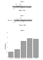
- Figure 8 shows a comparison of deviations from a perfect flight path due to flutter movements for balls having the same seam and pseudo-seam distribution, but different seam cross-sections and poorly processed seams, respectively.
- Figure 8 shows that a ball having perfect (pseudo-) seams with a width of 2 mm and a depth of 1 mm causes the lowest amount of flutter deviations.
- the average deviation increases for a ball having glue residues in the seams to a ball having 15 % and 20 % "faulty" (pseudo-) seams, respectively, up to a ball wherein all (pseudo-) seams have a width of 4 mm and a depth of 1 mm.
- the comparison shows that the values indicated in the claims of a preferred width of 1 mm to 3 mm, preferably 2 mm and a depth of 0.5 mm to 2 mm, preferably 1 mm, indeed contribute to substantial improvements in the precision of flight path.
Landscapes
- Health & Medical Sciences (AREA)
- General Health & Medical Sciences (AREA)
- Physical Education & Sports Medicine (AREA)
- Footwear And Its Accessory, Manufacturing Method And Apparatuses (AREA)
Abstract
Description
- The present invention relates to an inflatable ball, in particular a soccer ball, having a shell comprising a plurality of panels.
- Soccer balls, but also other inflatable balls, are typically produced as follows: In a first step an inner bladder, which can be made from latex, is reinforced with a carcass, or by a nylon thread wound around the bladder. An outer shell is then arranged on the carcass or on the nylon winding.
- For simple balls the shell can be integrally formed out of a plastic material. Alternatively, two preformed half shells of the ball shell are connected to each other, for example by gluing or sealing, as disclosed in
Figure 5 of theUS 2009/0011878 . The present invention, however, is related to high quality balls. For high quality balls the shell is composed of a multitude of prefabricated panels. In order to clearly distinguish the two fundamentally different constructions of a ball shell, a panel is in the following understood as being a separately prefabricated portion which forms less than a half of the ball shell. - The panels must be suitably attached relative to each other, for example by the well-known sewing of their edges or by gluing to the surface of the carcass. A direct gluing or (laser) welding of the edges of the panels to each other is also conceivable. For the sake of simplicity, the region wherein two adjacent panels contact each other, is simply called a "seam" in the following description, regardless of whether the panels are actually sewn to each other in a standard manner or whether they are fixed relative to each other in another way for providing the outer shell of the ball.
- In the past, the shell of soccer balls consisted typically of 32 panels having pentagonal and/or hexagonal shapes. More recent ball designs have a lower number of larger panels. The new ball designs improve the control of the ball by the player, since each seam creates an inhomogenity, typically a localized stiffness, in the outer shell so that the ball reacts differently when kicked with a shoe in the centre of a panel than when being kicked in the seam area. Unavoidable production tolerances during the manufacture of the seam result in an even greater inhomogeneity. This is a further reason why the player cannot perfectly control the ball and why a shot ball does not follow a precise flight pass. Furthermore, the arrangement of many seams leads to deviations from perfect sphericity.
- Using larger panels reduces the above mentioned problems, since fewer seams are needed for the manufacture of the overall shell of a ball having a given size. In addition, the manufacturing costs are reduced for larger panels, since less effort is needed to interconnect the panels and/or to arrange them on the carcass. Also the production tolerances are lower since there are fewer possibilities to create faulty seams during production. This applies to both the frequency of occurrence as well as to the extent of such production tolerances.
- However, applicant has realized that balls having large panels can have negative flight properties and can for example lead to instability. Due to aerodynamic effects there can be unintended and unpredictable flutter movements of the ball, as schematically shown in
Figure 1 . It is immediately apparent that such aerodynamic effects essentially impair a controlled play and precise shots. Similar problems also occur for inflatable balls for others sports, such as handball and volley-ball. - For improving the aerodynamic properties, it is known from the
US 4 318 544 to provide a soccer ball with seven parallel grooves extending in a uniform pentagonal arrangement over the complete shell of the ball. The arrangement is such that there are no grooves on certain panels of the shell of the ball, whereas up to three groups of seven parallel grooves contact each other on other panels. - While this arrangement may improve the flight properties of the ball, it does not improve precision during play. The extremely different surface design of the panels leads to a very different behaviour of the ball at the shoe. Both, during dribbling, but also for an aimed shot, the ball will behave differently depending on whether the shoe of the player hits a panel provided with the seven parallel grooves or a standard panel without any grooves.
- The present invention is therefore based on the problem to provide a ball, in particular a soccer ball, having good properties both at the shoe but also in the air and therefore allows a more precise play.
- The present invention solves this problem by a ball according to
claim 1. In one embodiment, the ball comprises an outer shell having a plurality of panels, wherein the panels are interconnected by seams. Each panel comprises at least one pseudo-seam, which extends at least over a part of an outer surface of the panel. - Due to the pseudo-seams of the invention and their distribution on each panel, the panels of the ball of the invention can be made larger so that the number and the lengths of the seams of the outer shell are reduced. In contrast to real seams, the pseudo-seams have no practical influence on the deformation properties and the contact properties of the panels. However, they have approximately the same aerodynamic effect as real seams and thereby avoid the unintended flutter movements in the flight path. This applies in particular, if the pseudo-seams have a cross-sectional shape corresponding essentially to the cross-sectional shape of a seam between two panels, for example an essentially V- or U-shaped cross section having a width of 1 - 3 mm, preferably 2 mm, and a depth of 0.5 - 2 mm, preferably 1 mm.
- The term "essentially" means in this context as well as generally within the present description an accuracy within the limits of production tolerances.
- In contrast to the prior art according to the above explained
US 4 318 544 , each panel comprises at least one pseudo-seam so that the effect on the aerodynamic properties is evenly distributed over all panels and thereby the complete outer shell. This leads to improved flight properties. Also the local modification of the deformation properties and the contact properties by the pseudo-seam, which are only minor, is evenly distributed on each panel. As a result, a ball is provided which can be perfectly controlled on the shoe and in the air and allows a very precise play. - Apart from the more homogeneous deformation and contact properties and the better flight properties, the ball of the invention can also be more cost-efficiently produced since the outer shell is assembled from a lower number of larger panels. Gluing, sewing or any other method to interconnect the panels therefore requires less process steps and working time and can be performed with lower production tolerances.
- Preferably, the pseudo-seams extend over the outer surface such that each panel is divided into at least two sub-panels. From an aerodynamical point of view, the ball therefore appears as if it was made of a plurality of small panels and enables precise flight paths without any flutter movements.
- For an even distribution over the outer surface it is preferred, if the pseudo-seams are not parallel to one another on the outer surface of a panel. On the contrary, in a preferred embodiment each pseudo-seam either interconnects essentially two seams, or it forms a closed curve in the outer surface of the panel. Other embodiments are also conceivable in which each panel is divided into four sub-panels by three arcuate pseudo-seams and/or modifications in which one or several additional pseudo-seams are provided which extend parallel to an edge of a sub-panel over at least a part of its surface.
- As already mentioned, the outer shell of the ball of the invention can be manufactured from a lower number of panels. Preferably, the outer shell comprises twelve or less, preferably eight panels. As a result, a ball is provided having essentially more homogeneous deformation and contact properties so that it can be precisely controlled by the shoe of the player.
- Presently, an arrangement is particularly preferred wherein the outer shell comprises a first and a second group of panels, each panel of the first group having the shape of a round triangle with convex edges and each panel of the second group having six corners connected with alternating concave edges and essentially straight edges. The convex edge of a panel of the first group can form a seam with the concave edge of a panel of the second group. Extensive testing has shown that such panel shapes and the resulting seam distribution is particularly advantageous for the properties of the ball.
- In order to avoid excessive tensions inside the shell, it is further preferred if the panels comprise a domed, three-dimensional shape prior to interconnecting them to form the outer shell. This can be achieved by suitable manufacturing methods of the materials used for the panels, such as deep-drawing using a domed mould. Injection moulding of the panels is however also conceivable to manufacture complex designs with little effort.
- In addition to the pseudo-seams, which serve for improving the aerodynamic properties, it is preferred if each panel further comprises a surface texture comprising corrugations having preferably a height of ≤ 0.5 mm, preferably ≤ 0.05 mm. Such corrugations are essentially smaller than the pseudo-seams and are therefore of less relevance for the aerodynamic properties of the ball. However, they improve the grip of the ball, in particular under wet conditions and therefore facilitate ball control and catching or halting of the ball by the goal keeper.
- In the presently particularly preferred embodiment of the invention, each panel comprises at least one backing material and at least one surface material, wherein the pseudo-seam is preferably provided in both the backing material and the surface material.
- Preferably, the backing material comprises a foamed material and the surface material comprises at least one TPU film. Other materials can also be used for the plastic films, for example PU, PA, or PVC. The pseudo-seams and/or the surface texture can be created in many different ways, such as master forming of the surface material and/or the backing material, for example by (multi-component) injection moulding, vacuum-forming, deep-drawing and/or laser etching of the TPU film and/or the backing material.
- Further modifications of the ball of the invention are defined in further dependent claims.
- In the following, aspects of the present invention are described in more detail with reference to the accompanying figures. These figures show:
- Fig. 1:
- a schematic presentation of the flutter movement of a ball due to aerodynamic effects in top view;
- Fig. 2a, b:
- presentations of a presently preferred embodiment of a ball according to the present invention;
- Fig. 3:
- a detailed presentation of a panel of a first group of panels in the embodiment of
Figures 2a , b; - Fig. 4:
- a detailed presentation of a panel of the second group of panels in the embodiment of
Figures 2a , b; - Fig. 5:
- a two-dimensional presentation of all of the panels of the embodiments of
Figures 2a , b; - Fig. 6:
- a schematic presentation of a seam between two panels;
- Fig. 7:
- a schematic presentation of a pseudo-seam;
- Fig. 8:
- a diagram for comparing flutter movements of balls with different geometries and qualities of the seams;
- Fig.9:
- a schematic representation of an embodiment of a ball with pseudoseams.
- In the following, preferred embodiments and modifications of the present invention are described with reference to a soccer ball. However, it is to be understood that the present invention is not limited to soccer balls. On the contrary, also other inflatable balls, such as handballs, basketballs, volleyballs, balls for American Football etc. may comprise the features of the present invention.
-
Figure 1 illustrates the basic problem of a flutter movement of a ball. Without aerodynamic effects, the flight path of theball 1 would follow astraight trajectory 2 into the right corner of thegoal 10. However, due to aerodynamic effects, it is possible under certain conditions that lateral forces are exerted on the ball. The direction of these lateral forces can change over the flight path so that theball 1 moves in the end along thecurved trajectory 3. It is apparent that such a flight behaviour impairs a precise play. - Extensive experimental tests of applicant in a wind tunnel have shown that the probability of flutter movements occurring depends on a number of parameters. An important parameter is, how "smooth" the surface of the ball is. Balls having an outer shell made from a plurality of small panels, such as the ball shown in
Figure 1 , which consists of 32 pentagonal and/or hexagonal shaped panels, have generally a lower tendency to flutter movements than balls having an outer shell consisting of a lower number of larger panels. The high number of seams on the surface of a conventional ball avoids the asymmetric separation of turbulences and thereby the flutter movement of the ball. Apparently, it is decisive how many seams are met by the air flow around the ball. - However, it was already mentioned in the introductory part that the arrangement of the plurality of seams causes other difficulties, such as inhomogeneous deformation properties and contact properties of the ball over its outer shell, high manufacturing costs and large production tolerances. The latter can also negatively affect the good flight properties of such a ball. If not all of the seams are perfect, this may cause substantial deviations from a straight flight path.
-
Figures 2a and2b present an embodiment of aball 20 according to the present invention, which overcomes these difficulties but which provides a flight path without a noticeable flutter movement. The presentedball 20 comprises two groups ofpanels Figures 3 and4 .Panels 30 of the first group have an essentially round triangular shape, wherein not only the corners of the triangle are rounded but wherein also the three side edges are provided with a convex curvature.Panels 40 of the second group have six corners, which are connected by alternating concave edges and essentially straight edges. - Where the edges of the
panels ball 20 comprisesseams 50. Theseams 50 can be provided in many different ways. In the presented embodiment, thepanels adjacent panels seams 50 are provided as bonded seams. However, it is also conceivable to interconnect thepanels seams 50, such as by conventional sewing methods or by welding a suitable plastic material or the like. Another option is to glue thepanels adjacent panels seams 50 are exclusively defined by the contact area or the transition region between twoadjacent panels - Applicant has found that the deterioration of the flight properties due to the use of a lower number of larger panels can be avoided if
pseudo-seams 60 are arranged on the surface of thepanels figures 6 and 7 and described in more detail below, the pseudo-seams 60 on the surface of thepanels ball 20 obtains aerodynamic properties corresponding to a ball having an essentially higher number of panels. In particular, the above described flutter movement of the ball is to a large extend avoided. - As can be seen in
Figures 2a and2b , threepseudo-seams 60 extend in the preferred embodiment in an arcuate manner over the surface of thepanel 40. Thepanel 40 is thus divided into four sub-panels having essentially the same size. The pseudo-seams 60 extend separately from each other and are not parallel to one another on at least a part of the surface of thepanel 40. Further, they meet theseams 50 in an essentially orthogonal arrangement, however, without intersecting theseams 50. In another embodiment, it is, however, also possible that the pseudo-seams 60 actually intersect the seams. - The surface of the
panels 30 of the other group comprises in the preferred embodiment also a pseudo-seam 60. The pseudo-seam 60 forms a closed curve and extends essentially parallel to theseam 50, which delimits thepanel 30. Also thepanel 30 is divided by the arrangement of the pseudo-seam 60 into two sub-panels. Ideally, these sub-panels have approximately the same surface area. -
Figures 3 and4 show detailed presentations of the panels 30 (Figure 3 ) and 40 (Figure 4 ), respectively. Apart from the already explained pseudo-seams 60, the Figures show that theindividual panels ball 20 have preferably a domed, three-dimensional shape after their manufacture but before being glued to the carcass. In contrast to the panels of a standard soccer ball made from 32 pentagonal and/or hexagonal shaped panels, which are typically punched out of a flat shell material, such as (artificial) leather, and which are brought into a three-dimensional shape only on the carcass/bladder of the ball, thepanels Figures 3 and4 already prior to being attached to theball 20. As a result, once assembled on the carcass, excessive tensions in thepanels ball 20. This is particularly important for aball 20 having very large panels. However, the described domed shape is also preferable for smaller panels. An exemplary manufacturing method for domed, three-dimensional panels is disclosed in theEP 1 424 105 A1 -
Figures 3 and4 show in addition the preferred shape of the edges of the twopanels panel 30 hasconvex edges 31, which after attachment to the carcass of a ball 20 (not shown) form aseam 50 together with corresponding concave edges 41 of thepanels 40. The long, slightlycurved seam 50 fits particularly well to the spherical shape of the final ball 20 (cf.Figures 2a , and b) and thus avoids tensions and the creation of stiff areas along theseam 50.Figure 4 shows in addition the essentiallystraight edges 42, which alternate with the concave edges 41. -
Figure 5 shows a schematic presentation of the preferred panel shapes 30, 40 and their relative arrangement after "unfolding" the outer shell of theball 20. It can be seen, that the overall outer shell is made from only eightpanels panels 30 and four of which have the shape of the above explainedpanels 40. It is apparent that the effort but also the manufacturing tolerances of the seams are essentially lower for such a small number of panels than in case of the standard 32 pentagonal and/or hexagonal shaped panels. However, neither the above described panel shapes, nor the use of exactly eight panels is essential for the present invention. Other panel shapes and - numbers, for example twelve, can also lead to advantageous ball properties. In another preferred embodiment six uniform panels are used. -
Figure 5 shows in addition once more the pseudo-seams 60, extending on thepanels panels 30 can be seen, which extends essentially parallel to the edge of thepanel 30. Also the threeindividual pseudo-seams 60 on thepanels 40 can be seen. Thepseudo seams 60 extend from the edge of apanel 40 initially in a direction essentially orthogonal to the edge of the panel and then in an arcuate manner over the surface of the panel, thereby dividing thepanel 40 into four sub-panels. Tests in a wind tunnel have shown that the panel shapes 30, 40 and the distribution of the pseudo-seams as shown inFigure 5 lead to particular advantageous flight properties of the ball, showing the lowest amount of flutter movements. -
Figure 9 represents a further preferred embodiment. Instead of pseudo-seams in the form of a closed curve, pseudo-seams 60' are arranged on thepanels 30 so that they essentially extend from oneseam 50 to anotherseam 50 thereby dividing eachpanel 30 into four sub-panels in a similar manner to the pseudo-seams 60 onpanel 40. In a modification of this embodiment (not shown) further pseudo-seams extend parallel to the curved pseudo-seams on thepanels panels - In addition to the described
pseudo-seams 60, 60' the hatching inFigure 5 indicates asurface texture 70 on thepanels 40. In the preferred embodiment, with the exception of the edge regions of thepanels surface texture 70 covers the complete area of eachpanel ball 20 is improved, which facilitates on the one hand the control of the ball with the foot, but also catching the ball by the goal keeper. Thesurface texture 70 is preferably provided by a number of individual projections or recesses on thepanels panels - An important aspect is that the projections do not excessively extend above the surface of the panel, which would lead to a substantial influence on the aerodynamic properties of the ball. The height of the projections of the
surface texture 70 is therefore preferably ≤ 0.5 mm. In the preferred embodiment, the height is only ≤ 0.05 mm. - The pseudo-seams 60 as well as the
surface texture 70 of thepanels EP 1 424 105 A1panel EP 0 894 514 A2 of applicant. According to the method of manufacturing aball 20 disclosed inEP 1 424 105 A1surface texture 70. - In a similar manner, the backing material is foamed, which may at the same time be interconnected to the surface material. The produced
panels seams 50 by gluing, welding, sewing or the like (cf. alsoFigure 6 ). - Apart from the described deep-drawing, also other forming methods for the preferred plastic materials known to the person skilled in the art can be used for producing the
panels surface texture 70. - Injection moulding is also conceivable for master forming of the panels. In doing so, the surface material and the backing material for a panel can either be successively master formed and glued or can be concurrently injected moulded as a two component injection moulding or can be injection moulded in short succession with the aid of an insert in layers in a mould. Preferred materials comprise two component foams made from materials with different densities or with different colours. Foams of different colours which are arranged in a panel side by side with a transparent TPU film as a surface material offer new design possibilities. A hybrid type of master forming and shaping is also conceivable if, for example the injection moulding part which is not completely hardened, is additionally deformed by embossing or by other methods.
- Moreover, it is also possible to later process the surface, for example by etching with a laser or embossing with a suitable mechanical device. Etching with a laser is particularly advantageous, if the precision of the created structure is important as in the case of the pseudo-seams 60 (see below). Also conceivable are mixed manufacturing methods, wherein some of the elements of the surface of the
panels - Regardless of the manufacturing methods used, the
panels EP 0 894 514 A2 . Using several TPU layers with different colours for the surface material enables the creation of a particular optical design, if a laser subsequently selectively etches away parts of an upper TPU layer to expose a lower TPU layer of different colour. This technique enables for example a simple personalization of a ball after its fabrication. Individual information or graphics can be generated with a laser for example after an important match. -
Figures 6 and 7 illustrate the similarity of the shape of theseams 50 and the pseudo-seams 60. These Figures are schematic drawings which are not true to scale. As can be seen, theseams 50 as well as the pseudo-seam 60 have preferably a cross-section with a width of approximately 2 mm. In order to be as similar as possible to the shape of theseam 50 and to create similar aerodynamical effects, the pseudo-seam 60 has an essentially V- or U-shaped cross-section with a depth of preferably 1 mm (seeFigure 7 ). For the long-term stability of thepanel Figure 7 , the pseudo-seam 60 is not only provided in thesurface material 71 but also in thebacking material 72. - The preferred values of a width of approximately 2 mm and a depth of approximately 1 mm are not essential for the present invention; however, they contribute to an optimisation of the flight properties of the
ball 20. -
Figure 8 shows a comparison of deviations from a perfect flight path due to flutter movements for balls having the same seam and pseudo-seam distribution, but different seam cross-sections and poorly processed seams, respectively. -
Figure 8 shows that a ball having perfect (pseudo-) seams with a width of 2 mm and a depth of 1 mm causes the lowest amount of flutter deviations. The average deviation increases for a ball having glue residues in the seams to a ball having 15 % and 20 % "faulty" (pseudo-) seams, respectively, up to a ball wherein all (pseudo-) seams have a width of 4 mm and a depth of 1 mm. The comparison shows that the values indicated in the claims of a preferred width of 1 mm to 3 mm, preferably 2 mm and a depth of 0.5 mm to 2 mm, preferably 1 mm, indeed contribute to substantial improvements in the precision of flight path.
Claims (15)
- Inflatable ball (20), in particular soccer ball, having an outer shell, comprising a plurality of panels (30, 40), whereina. the panels (30, 40) are interconnected by seams (50); andb. each panel (30, 40) comprises at least one pseudo-seam (60) extending at least over a part of an outer surface of the panel (30, 40).
- Inflatable ball (20) according to claim 1, wherein the pseudo-seams (60) have a cross-sectional shape corresponding essentially to a cross-sectional shape of the seam (50) between two panels (30, 40).
- Inflatable ball (20) according to the preceding claim, wherein the pseudo-seams (60) have an essentially V- or U-shaped cross-section with a width of 1 mm to 3 mm, preferably 2 mm, and a depth of 0.5 mm to 2 mm, preferably 1 mm.
- Inflatable ball (20) according to one of the preceding claims, wherein the pseudo-seams (60) extend over the outer surface of the panel (30, 40) such that each panel (30, 40) is divided into at least two sub-panels.
- Inflatable ball (20) according to one of the preceding claims, wherein each pseudo-seam (60) either essentially interconnects two seams (50) or forms a closed curve on the outer surface of the panel (30).
- Inflatable ball (20) according to claim 5, wherein each pseudo-seam (60), which forms a closed curve, extends essentially parallel to the seam (50) surrounding the respective panel (30).
- Inflatable ball (20) according to one of the preceding claims, wherein the outer shell comprises a first and a second group of panels (30, 40), wherein each panel (30) of the first group has the shape of a round triangle with convex edges (31) and wherein each panel (40) of the second group comprises six corners connected by alternating concave edges (41) and essentially straight edges (42).
- Inflatable ball (20) according to the preceding claim, wherein the convex edge (31) of a panel (30) of the first group forms a seam (50) together with the concave edge (41) of a panel (40) of the second group.
- Inflatable ball (20) according to one of the preceding claims, wherein each panel (30, 40) further comprises a surface texture (70) having preferably a height of ≤ 0.5 mm, most preferably ≤ 0.05 mm.
- Inflatable ball (20) according to one of the preceding claims, wherein each panel (30, 40) comprises at least one backing material (72) and at least one surface material (71) and wherein the pseudo-seams (60) are provided in the backing material (72) and/or the surface material (71).
- Inflatable ball (20) according to one of the preceding claims, wherein the pseudo-seams (60) and/or the surface texture (70) are created by vacuum moulding of the surface material (71).
- Inflatable ball (20) according to one of the preceding claims, wherein the pseudo-seams (60) and/or the surface texture (70) are created by deep-drawing of the surface material (71).
- Inflatable ball (20) according to one of the preceding claims, wherein the pseudo-seams (60) and/or the surface texture (70) are created by laser etching of the surface material (71) and/or the backing material (72).
- Inflatable ball (20) according to one of the preceding claims, wherein the pseudo-seams (60) and/or the surface texture (70) are created by embossing the surface material (71) and/or the backing material (72).
- Inflatable ball (20) according to one of the preceding claims, wherein the pseudo-seams (60) and/or the surface texture (70) are created by master forming of the surface material (71) and/or the backing material (72).
Priority Applications (1)
| Application Number | Priority Date | Filing Date | Title |
|---|---|---|---|
| EP14198479.9A EP2883580B1 (en) | 2009-04-03 | 2010-03-03 | Ball with pseudo seam |
Applications Claiming Priority (1)
| Application Number | Priority Date | Filing Date | Title |
|---|---|---|---|
| DE102009016287A DE102009016287B3 (en) | 2009-04-03 | 2009-04-03 | ball |
Related Child Applications (1)
| Application Number | Title | Priority Date | Filing Date |
|---|---|---|---|
| EP14198479.9A Division EP2883580B1 (en) | 2009-04-03 | 2010-03-03 | Ball with pseudo seam |
Publications (2)
| Publication Number | Publication Date |
|---|---|
| EP2243520A1 true EP2243520A1 (en) | 2010-10-27 |
| EP2243520B1 EP2243520B1 (en) | 2015-01-14 |
Family
ID=42238654
Family Applications (2)
| Application Number | Title | Priority Date | Filing Date |
|---|---|---|---|
| EP14198479.9A Active EP2883580B1 (en) | 2009-04-03 | 2010-03-03 | Ball with pseudo seam |
| EP10155323.8A Active EP2243520B1 (en) | 2009-04-03 | 2010-03-03 | Ball with pseudo seams |
Family Applications Before (1)
| Application Number | Title | Priority Date | Filing Date |
|---|---|---|---|
| EP14198479.9A Active EP2883580B1 (en) | 2009-04-03 | 2010-03-03 | Ball with pseudo seam |
Country Status (5)
| Country | Link |
|---|---|
| US (1) | US8529386B2 (en) |
| EP (2) | EP2883580B1 (en) |
| JP (1) | JP5137215B2 (en) |
| CN (1) | CN101856552B (en) |
| DE (1) | DE102009016287B3 (en) |
Cited By (3)
| Publication number | Priority date | Publication date | Assignee | Title |
|---|---|---|---|---|
| EP3000509A1 (en) | 2014-09-25 | 2016-03-30 | Adidas AG | Manufacturing method for an outer layer for a panel of a ball |
| WO2018160353A1 (en) | 2017-02-28 | 2018-09-07 | Nike Innovate C.V. | Sports ball |
| WO2020046557A1 (en) * | 2018-08-31 | 2020-03-05 | Nike Innovate C.V. | Sports ball |
Families Citing this family (28)
| Publication number | Priority date | Publication date | Assignee | Title |
|---|---|---|---|---|
| JP5427030B2 (en) * | 2007-04-12 | 2014-02-26 | 株式会社モルテン | ball |
| PT105457B (en) * | 2010-12-27 | 2018-04-16 | Inst Superior Tecnico | INFLATABLE BALL FOR SOCCER AND RECREATIONAL ACTIVITIES |
| US8602927B2 (en) * | 2010-12-29 | 2013-12-10 | Vertex L.L.C. | Game ball and method of manufacturing same |
| US9162114B1 (en) | 2010-12-29 | 2015-10-20 | Novation Iq Llc | Game ball and method of manufacturing same |
| JP5689339B2 (en) | 2011-03-09 | 2015-03-25 | 株式会社ミカサ | Exercise ball |
| TWI457162B (en) * | 2012-02-15 | 2014-10-21 | San Fang Chemical Industry Co | Ball shaped product and method for making the same |
| CN103170110A (en) * | 2013-03-22 | 2013-06-26 | 南京绎霖国际贸易有限公司 | Playing ball with flat joint and manufacture method thereof |
| DE102015204151B4 (en) * | 2015-03-09 | 2025-12-24 | Adidas Ag | Ball, especially football, and method for manufacturing a ball |
| CN113693330B (en) * | 2015-04-08 | 2023-10-10 | 耐克创新有限合伙公司 | Method of manufacturing a bladder element with etched features and article having such a bladder element |
| DE102015209797B3 (en) | 2015-05-28 | 2016-07-14 | Adidas Ag | Panel for a ball |
| WO2017176979A1 (en) | 2016-04-06 | 2017-10-12 | Under Armour, Inc. | Sports ball |
| CN109862948B (en) * | 2016-10-24 | 2022-02-11 | 耐克创新有限合伙公司 | Sports ball and housing defining primary and secondary channels |
| US10350460B2 (en) * | 2017-02-28 | 2019-07-16 | Nike, Inc. | Sports ball |
| JP6458083B2 (en) * | 2017-05-22 | 2019-01-23 | 株式会社モルテン | ball |
| US10258836B2 (en) * | 2017-05-25 | 2019-04-16 | Nike, Inc. | Sports ball with mechanoluminescence |
| USD863473S1 (en) | 2017-08-15 | 2019-10-15 | Nike, Inc. | Ball |
| USD863475S1 (en) | 2017-08-15 | 2019-10-15 | Nike, Inc. | Ball |
| USD863474S1 (en) | 2017-08-15 | 2019-10-15 | Nike, Inc. | Ball |
| USD837908S1 (en) * | 2017-10-25 | 2019-01-08 | Exemplar Design, Llc | Medicine ball |
| WO2019147694A1 (en) * | 2018-01-23 | 2019-08-01 | Company 5, Llc | Bouncing ball with bounce counter |
| JP7072795B2 (en) * | 2018-02-07 | 2022-05-23 | 株式会社モルテン | Exercise ball |
| US11148013B2 (en) * | 2018-08-31 | 2021-10-19 | Nike, Inc. | Sports ball |
| WO2020150593A1 (en) * | 2019-01-18 | 2020-07-23 | Nike Innovate C.V. | Sports ball |
| WO2021002983A1 (en) | 2019-07-03 | 2021-01-07 | Nike Innovate C.V. | Sports ball with wickerbill |
| EP4106890A1 (en) | 2020-02-21 | 2022-12-28 | NIKE Innovate C.V. | Sports ball with staggered surface features |
| DE102021202706A1 (en) * | 2021-03-19 | 2022-09-22 | Adidas Ag | inflatable ball |
| EP4653065A1 (en) * | 2024-05-24 | 2025-11-26 | Weststar Consultancy | Method for producing a sports ball |
| DE102024118151A1 (en) | 2024-06-27 | 2025-12-31 | Adidas Ag | Ball with a faceted surface design and a method for producing a faceted surface design. |
Citations (5)
| Publication number | Priority date | Publication date | Assignee | Title |
|---|---|---|---|---|
| US4318544A (en) | 1980-10-30 | 1982-03-09 | W. H. Brine Company | Game ball |
| EP0894514A2 (en) | 1997-07-30 | 1999-02-03 | adidas International B.V. | Football |
| EP1424105A1 (en) | 2002-11-26 | 2004-06-02 | adidas International Marketing B.V. | Method for the manufacture of parts of a ball and method for the manufacture of a ball |
| BE1016122A6 (en) * | 2004-07-16 | 2006-03-07 | Franck Jan | Football, has panels with recessed regions in form of holes, embossed areas or grooves |
| US20090011878A1 (en) | 2007-07-02 | 2009-01-08 | Tsing Ming Ou | Molded sportsball without molding mark and manufacturing method thereof |
Family Cites Families (109)
| Publication number | Priority date | Publication date | Assignee | Title |
|---|---|---|---|---|
| US1559117A (en) * | 1923-10-11 | 1925-10-27 | Drapermaynard Company | Football |
| US1931429A (en) * | 1932-01-05 | 1933-10-17 | John L Buckner | Football |
| US2280314A (en) * | 1938-02-12 | 1942-04-21 | Rawlings Mfg Co | Method of making inflatable balls |
| US2149465A (en) * | 1938-08-17 | 1939-03-07 | John T Riddell | Method of making playing balls |
| US4000894A (en) * | 1975-06-23 | 1977-01-04 | Pepsico, Inc. | Game ball |
| JPS568701Y2 (en) * | 1977-05-23 | 1981-02-25 | ||
| JPS583710B2 (en) | 1978-12-30 | 1983-01-22 | モルテンゴム工業株式会社 | Manufacturing method for leather balls |
| USD268853S (en) * | 1981-02-09 | 1983-05-03 | W. H. Brine Company | Game ball |
| JPS58152576A (en) | 1982-03-08 | 1983-09-10 | 株式会社モルテン | Production leather lined ball |
| JPS59125574A (en) | 1982-12-29 | 1984-07-19 | モルテンゴム工業株式会社 | Air contained ball and production thereof |
| JPS59125578A (en) * | 1983-01-08 | 1984-07-19 | 株式会社モルテン | Production of leather covered ball |
| JPS60199472A (en) | 1984-03-26 | 1985-10-08 | 株式会社モルテン | Athletic ball |
| JPS59232562A (en) | 1983-06-16 | 1984-12-27 | 株式会社モルテン | Athletic ball |
| JPS6024855A (en) | 1983-06-16 | 1985-02-07 | 株式会社モルテン | Athletic ball |
| JPS60199474A (en) | 1984-03-26 | 1985-10-08 | 株式会社モルテン | Athletic ball |
| JPS60199473A (en) | 1984-03-26 | 1985-10-08 | 株式会社モルテン | Athletic ball |
| US4570931A (en) * | 1984-04-03 | 1986-02-18 | Wilson Sporting Goods Co. | Basketball |
| JPS6018184A (en) | 1984-04-06 | 1985-01-30 | 株式会社 モルテン | Athletic ball |
| US4856781A (en) * | 1986-01-16 | 1989-08-15 | Molten Corporation | Game ball |
| DE3726830C1 (en) | 1987-08-12 | 1988-12-22 | Uhl Sportartikel Karl | Ball cover, especially for footballs |
| JP2619913B2 (en) | 1987-10-23 | 1997-06-11 | 株式会社モルテン | Surface panel for ball balls |
| US4830373A (en) * | 1987-12-16 | 1989-05-16 | Rudolf Dehnert | Soccer ball |
| JP2617515B2 (en) | 1987-12-23 | 1997-06-04 | 株式会社モルテン | Surface panel of game ball and method of manufacturing the same |
| US5165685A (en) * | 1992-01-06 | 1992-11-24 | Hynes John P | Game ball |
| DE4434751C2 (en) * | 1994-09-29 | 1996-10-17 | Montero Jose | Ball cover |
| JP3390586B2 (en) | 1994-10-05 | 2003-03-24 | 株式会社モルテン | Ball for ball games and method of manufacturing the same |
| US5470060A (en) * | 1994-11-04 | 1995-11-28 | Premium Products, Inc. | Football with odd number of panels |
| JP3512256B2 (en) | 1994-12-28 | 2004-03-29 | ユニチカ株式会社 | Civil engineering sheet |
| JPH08196662A (en) | 1995-01-30 | 1996-08-06 | Molten Corp | Ball for ball game |
| DE19541395C2 (en) * | 1995-11-07 | 1998-01-22 | Uhlsport Gmbh | Ball cover, in particular for soccer balls |
| USD386230S (en) * | 1996-05-24 | 1997-11-11 | Flying Clipper | Game foot bag |
| US5851161A (en) * | 1997-07-15 | 1998-12-22 | Sassak; Mark S. | Grippable surface for throwable objects |
| US6302815B1 (en) * | 1997-09-22 | 2001-10-16 | Molten Corporation | Ball for a ball game |
| JPH1189971A (en) | 1997-09-22 | 1999-04-06 | Molten Corp | Ball for ball game |
| USD416961S (en) * | 1997-09-27 | 1999-11-23 | Umbro Trademark, Inc. | Ball for use in sports and games |
| US5888157A (en) * | 1997-10-03 | 1999-03-30 | Wilson Sporting Goods Co. | Football |
| USD405486S (en) * | 1997-11-03 | 1999-02-09 | Joyful Long International, Ltd. | Soccer ball |
| JPH11155980A (en) | 1997-11-27 | 1999-06-15 | Molten Corp | Ball for ball game and manufacture thereof |
| US5931752A (en) * | 1998-01-15 | 1999-08-03 | Wilson Sporting Goods Co. | Inflatable game ball with laid-in channel or logo |
| USD408876S (en) * | 1998-02-06 | 1999-04-27 | Lisco, Inc. | Basketball |
| USD439294S1 (en) * | 1998-04-21 | 2001-03-20 | Mitre Sports International Ltd. | Ball for playing soccer (football) |
| TW407060B (en) * | 1998-05-22 | 2000-10-01 | Molten Corp | Ball for ball game |
| US6422961B1 (en) * | 1999-01-25 | 2002-07-23 | Spalding Sports Worldwide, Inc. | Rubber basketball with skived channel look |
| JP2000245875A (en) | 1999-02-26 | 2000-09-12 | Molten Corp | Ball for ball game |
| JP4497609B2 (en) | 1999-12-17 | 2010-07-07 | 株式会社モルテン | Ball for ball game |
| US6971965B1 (en) * | 2000-05-01 | 2005-12-06 | Molten Corporation | Ball for ball game and method for manufacturing the same |
| USD452721S1 (en) * | 2000-05-29 | 2002-01-01 | Mondo, S.P.A. | Ball |
| USD440614S1 (en) * | 2000-07-31 | 2001-04-17 | Jose C. Audero | Soccer ball |
| US6506135B2 (en) * | 2001-01-22 | 2003-01-14 | Top Ball Trading Co. | Inflatable sportsball with cushion layer |
| TW462300U (en) | 2001-03-20 | 2001-11-01 | Continental Chemical Ind Co Lt | Basketball with integrally formed granular grooves |
| JP4902830B2 (en) | 2001-07-25 | 2012-03-21 | 株式会社モルテン | Leather panel for ball for ball game and manufacturing method thereof |
| USD462732S1 (en) * | 2001-10-12 | 2002-09-10 | Rawlings Sporting Goods Company, Inc. | Ten paneled basketball |
| US6752732B2 (en) * | 2001-10-12 | 2004-06-22 | Rawlings Sporting Goods Company, Inc. | Basketball having nine to twelve cover panels |
| US6988969B2 (en) * | 2002-04-24 | 2006-01-24 | Nike, Inc. | Game ball with bridged panels |
| US6612948B1 (en) * | 2002-05-06 | 2003-09-02 | Arthur Miller | Non-slip inflatable sports ball |
| USD473275S1 (en) * | 2002-08-08 | 2003-04-15 | Franklin Sports, Inc. | Team sports ball |
| USD483424S1 (en) * | 2002-11-26 | 2003-12-09 | Franklin Sports, Inc. | Basketball |
| DE60234134D1 (en) * | 2002-12-20 | 2009-12-03 | Molten Corp | BALL FOR BALL GAMES AND METHOD FOR THE PRODUCTION THEREOF |
| US20040134136A1 (en) * | 2003-01-15 | 2004-07-15 | Shearing John Robert | Spherical enclosure suitable as a building structure, pressure vessel, vacuum vessel, or for storing liquids |
| BR8300122U (en) * | 2003-01-20 | 2004-10-26 | Roberto Estefano | Arrangement introduced in sports ball |
| USD548292S1 (en) * | 2006-11-30 | 2007-08-07 | Nike, Inc. | Ball |
| US8360905B2 (en) * | 2004-02-02 | 2013-01-29 | Nike, Inc. | Chromatic architecture for sports equipment |
| EP1738807B1 (en) * | 2004-04-09 | 2013-10-23 | Kuraray Co., Ltd. | Sheet material excelling in cushion and nonslip properties |
| DE202004011143U1 (en) * | 2004-07-16 | 2005-12-08 | Puma Aktiengesellschaft Rudolf Dassler Sport | ball case |
| USD511191S1 (en) * | 2004-08-18 | 2005-11-01 | Don Fryer | Basketball |
| CN1739826B (en) * | 2004-08-25 | 2014-11-19 | 唐雅芳 | Method for manufacturing leather ball piece |
| US7066853B2 (en) * | 2004-09-30 | 2006-06-27 | Yen-Li Chang | Method for manufacturing an inflatable ball and a ball made with the method |
| USD510113S1 (en) * | 2004-10-29 | 2005-09-27 | Russell Asset Management, Inc. | Eighteen panel soccer ball |
| US20060105866A1 (en) * | 2004-11-17 | 2006-05-18 | Hansan Ma | Football with a modified surface conferring altered aerodynamic properties |
| USD511551S1 (en) * | 2004-11-17 | 2005-11-15 | Russell Asset Management, Inc. | Basketball |
| DE102004056951B4 (en) * | 2004-11-25 | 2009-01-15 | Uhlsport Gmbh | Ball cover, in particular for footballs |
| USD529107S1 (en) * | 2005-01-27 | 2006-09-26 | Adidas International Marketing B.V. | Decorated panel assembly for a ball |
| USD520086S1 (en) * | 2005-01-27 | 2006-05-02 | Adidas International Marketing B.V. | Surface decoration for a ball or a ball panel |
| USD527432S1 (en) * | 2005-01-27 | 2006-08-29 | Adidas International Marketing B.V. | Ball |
| US7462119B2 (en) * | 2005-03-03 | 2008-12-09 | Russell Corporation | Spherical game ball with improved panels |
| US20060229150A1 (en) * | 2005-04-11 | 2006-10-12 | Ou Tsung M | Lamination inflatable sports ball |
| USD516647S1 (en) * | 2005-08-03 | 2006-03-07 | Chuang Yii Enterprise Co., Ltd. | Basketball |
| US20070037642A1 (en) * | 2005-08-11 | 2007-02-15 | Yen-Li Chang | Ball with an improved bladder carcass securely engaging with multiple cover panels |
| US7444770B2 (en) * | 2005-10-07 | 2008-11-04 | Wellington Jr James L | Designs on a sphere that exhibit spin induced contrast |
| US7601085B2 (en) * | 2005-11-04 | 2009-10-13 | Russell Brands, Llc | Sports ball and method of manufacturing |
| USD556275S1 (en) * | 2005-11-16 | 2007-11-27 | Samuel Crane | Ball |
| US20070117662A1 (en) * | 2005-11-18 | 2007-05-24 | Hansan Ma | Dimpled soccer ball |
| USD533239S1 (en) * | 2006-01-10 | 2006-12-05 | Continental Chemical Industries Co., Ltd. | Basketball |
| JP5002164B2 (en) * | 2006-02-08 | 2012-08-15 | モルテックス スポーツ リミテッド | Skin panel, ball for ball game, and manufacturing method thereof |
| USD544931S1 (en) * | 2006-02-21 | 2007-06-19 | Russell Corporation | Basketball |
| CN101489633B (en) * | 2006-07-26 | 2012-11-07 | 可乐丽股份有限公司 | Sheet-like object for ball and ball |
| USD544052S1 (en) * | 2006-08-02 | 2007-06-05 | Wilson Sporting Goods Co. | Basketball |
| US7585236B2 (en) * | 2006-08-02 | 2009-09-08 | Wilson Sporting Goods Co. | Game ball having optimally positioned grooves and/or ridges |
| US7862458B2 (en) * | 2006-09-20 | 2011-01-04 | Nike, Inc. | Panel configuration for a game ball |
| US7828681B2 (en) * | 2006-12-06 | 2010-11-09 | Nike, Inc. | Game ball |
| USD563495S1 (en) * | 2007-01-16 | 2008-03-04 | Abe Torres | Soccer ball |
| US20080176685A1 (en) * | 2007-01-22 | 2008-07-24 | Nike, Inc. | Football with inflatable bladder having integral grip areas |
| JP4871155B2 (en) | 2007-01-31 | 2012-02-08 | 株式会社モルテン | Ball for ball game and manufacturing method thereof |
| AU316699S (en) * | 2007-02-19 | 2007-11-05 | Mikasa Corp | Sporting ball |
| JP5427030B2 (en) | 2007-04-12 | 2014-02-26 | 株式会社モルテン | ball |
| USD558285S1 (en) * | 2007-05-11 | 2007-12-25 | Nike, Inc. | Ball |
| USD603916S1 (en) * | 2007-05-11 | 2009-11-10 | Nike, Inc. | Ball |
| JP5106931B2 (en) * | 2007-06-28 | 2012-12-26 | 株式会社クラレ | ball |
| JP2009006052A (en) | 2007-06-29 | 2009-01-15 | Molten Corp | Ball |
| DE202007013433U1 (en) * | 2007-09-24 | 2008-09-25 | Sohrabi, Esmail | Soccer |
| JP4787816B2 (en) | 2007-12-21 | 2011-10-05 | 株式会社モルテン | Ball for ball game |
| USD583427S1 (en) * | 2008-01-23 | 2008-12-23 | Ahmed Saghir | Ball |
| US8900077B2 (en) * | 2008-02-19 | 2014-12-02 | Topball Sports Inc. | Sportsball with integral ball casing and bladder body |
| US8182379B2 (en) * | 2008-06-27 | 2012-05-22 | Nike, Inc. | Sport balls and methods of manufacturing the sport balls |
| USD613354S1 (en) * | 2008-11-07 | 2010-04-06 | Adidas International Marketing B.V. | Ball |
| USD596249S1 (en) * | 2008-12-04 | 2009-07-14 | Broadscope International, Inc. | Novelty soccer ball |
| USD605240S1 (en) * | 2009-02-20 | 2009-12-01 | Gibson William G | Sports ball |
| USD634380S1 (en) * | 2010-06-25 | 2011-03-15 | Walling Jr Victor | Soccer ball |
| CN202136749U (en) | 2011-07-18 | 2012-02-08 | 邓建 | Basketball |
-
2009
- 2009-04-03 DE DE102009016287A patent/DE102009016287B3/en active Active
-
2010
- 2010-03-03 EP EP14198479.9A patent/EP2883580B1/en active Active
- 2010-03-03 EP EP10155323.8A patent/EP2243520B1/en active Active
- 2010-03-16 CN CN201010125148XA patent/CN101856552B/en active Active
- 2010-04-01 US US12/752,839 patent/US8529386B2/en active Active
- 2010-04-05 JP JP2010086772A patent/JP5137215B2/en active Active
Patent Citations (5)
| Publication number | Priority date | Publication date | Assignee | Title |
|---|---|---|---|---|
| US4318544A (en) | 1980-10-30 | 1982-03-09 | W. H. Brine Company | Game ball |
| EP0894514A2 (en) | 1997-07-30 | 1999-02-03 | adidas International B.V. | Football |
| EP1424105A1 (en) | 2002-11-26 | 2004-06-02 | adidas International Marketing B.V. | Method for the manufacture of parts of a ball and method for the manufacture of a ball |
| BE1016122A6 (en) * | 2004-07-16 | 2006-03-07 | Franck Jan | Football, has panels with recessed regions in form of holes, embossed areas or grooves |
| US20090011878A1 (en) | 2007-07-02 | 2009-01-08 | Tsing Ming Ou | Molded sportsball without molding mark and manufacturing method thereof |
Cited By (6)
| Publication number | Priority date | Publication date | Assignee | Title |
|---|---|---|---|---|
| EP3000509A1 (en) | 2014-09-25 | 2016-03-30 | Adidas AG | Manufacturing method for an outer layer for a panel of a ball |
| DE102014219396A1 (en) * | 2014-09-25 | 2016-03-31 | Adidas Ag | Production method for an outer layer for a panel of a ball |
| US10773448B2 (en) | 2014-09-25 | 2020-09-15 | Adidas Ag | Manufacturing method for an outer layer for a panel of a ball |
| WO2018160353A1 (en) | 2017-02-28 | 2018-09-07 | Nike Innovate C.V. | Sports ball |
| EP3589377A4 (en) * | 2017-02-28 | 2020-12-30 | NIKE Innovate C.V. | SPORTS BALL |
| WO2020046557A1 (en) * | 2018-08-31 | 2020-03-05 | Nike Innovate C.V. | Sports ball |
Also Published As
| Publication number | Publication date |
|---|---|
| DE102009016287B3 (en) | 2010-11-04 |
| CN101856552B (en) | 2013-06-19 |
| US8529386B2 (en) | 2013-09-10 |
| US20100255940A1 (en) | 2010-10-07 |
| EP2243520B1 (en) | 2015-01-14 |
| JP2010240427A (en) | 2010-10-28 |
| EP2883580A1 (en) | 2015-06-17 |
| JP5137215B2 (en) | 2013-02-06 |
| EP2883580B1 (en) | 2016-10-12 |
| CN101856552A (en) | 2010-10-13 |
Similar Documents
| Publication | Publication Date | Title |
|---|---|---|
| EP2243520B1 (en) | Ball with pseudo seams | |
| US12415114B2 (en) | Sports balls | |
| US12370414B2 (en) | Ball and method for its manufacture | |
| EP1424105B1 (en) | Method for the manufacture of parts of a ball and method for the manufacture of a ball | |
| US9504880B2 (en) | Football with aerodynamic lace | |
| US20070049434A1 (en) | Game ball | |
| JP5480210B2 (en) | A golf ball comprising a plurality of dimple types and / or a plurality of layers of various hardnesses. | |
| US20070117662A1 (en) | Dimpled soccer ball | |
| JP2012045382A (en) | Golf ball including multiple dimple types and/or multiple layers of different hardness | |
| KR20130091762A (en) | Artificial feathers for shuttlecocks, shuttlecock and method for producing artificial shuttlecock feathers | |
| JPH03118086A (en) | Improved dimple pattern | |
| JP2012040376A (en) | Golf balls including multiple dimple types and/or multiple layers of different hardnesses | |
| JP2012040373A (en) | Golf ball including a plurality of dimple types and/or a plurality of layers having various kinds of hardness | |
| US20240359061A1 (en) | Inflatable ball | |
| JP2012040375A (en) | Golf ball including a plurality of dimple types and/or a plurality of layers having various kinds of hardness | |
| US9833665B2 (en) | Golf ball dimple based on witch of Agnesi curve | |
| US20240278084A1 (en) | Basketball | |
| US20130172125A1 (en) | Golf ball dimples defined by superposed curves | |
| JP7860209B2 (en) | Inflatable ball | |
| CN118512752A (en) | 3D printed basketball | |
| CN121197775A (en) | Balls for ball games and their manufacturing methods |
Legal Events
| Date | Code | Title | Description |
|---|---|---|---|
| PUAI | Public reference made under article 153(3) epc to a published international application that has entered the european phase |
Free format text: ORIGINAL CODE: 0009012 |
|
| AK | Designated contracting states |
Kind code of ref document: A1 Designated state(s): AT BE BG CH CY CZ DE DK EE ES FI FR GB GR HR HU IE IS IT LI LT LU LV MC MK MT NL NO PL PT RO SE SI SK SM TR |
|
| AX | Request for extension of the european patent |
Extension state: AL BA ME RS |
|
| 17P | Request for examination filed |
Effective date: 20110427 |
|
| 17Q | First examination report despatched |
Effective date: 20130107 |
|
| GRAP | Despatch of communication of intention to grant a patent |
Free format text: ORIGINAL CODE: EPIDOSNIGR1 |
|
| RIC1 | Information provided on ipc code assigned before grant |
Ipc: A63B 69/00 20060101ALI20140728BHEP Ipc: A63B 45/02 20060101ALI20140728BHEP Ipc: A63B 41/08 20060101AFI20140728BHEP |
|
| INTG | Intention to grant announced |
Effective date: 20140812 |
|
| GRAS | Grant fee paid |
Free format text: ORIGINAL CODE: EPIDOSNIGR3 |
|
| GRAA | (expected) grant |
Free format text: ORIGINAL CODE: 0009210 |
|
| AK | Designated contracting states |
Kind code of ref document: B1 Designated state(s): AT BE BG CH CY CZ DE DK EE ES FI FR GB GR HR HU IE IS IT LI LT LU LV MC MK MT NL NO PL PT RO SE SI SK SM TR |
|
| REG | Reference to a national code |
Ref country code: GB Ref legal event code: FG4D |
|
| REG | Reference to a national code |
Ref country code: CH Ref legal event code: EP |
|
| REG | Reference to a national code |
Ref country code: IE Ref legal event code: FG4D |
|
| REG | Reference to a national code |
Ref country code: AT Ref legal event code: REF Ref document number: 706707 Country of ref document: AT Kind code of ref document: T Effective date: 20150215 |
|
| REG | Reference to a national code |
Ref country code: DE Ref legal event code: R096 Ref document number: 602010021753 Country of ref document: DE Effective date: 20150226 |
|
| REG | Reference to a national code |
Ref country code: NL Ref legal event code: VDEP Effective date: 20150114 |
|
| REG | Reference to a national code |
Ref country code: AT Ref legal event code: MK05 Ref document number: 706707 Country of ref document: AT Kind code of ref document: T Effective date: 20150114 |
|
| REG | Reference to a national code |
Ref country code: LT Ref legal event code: MG4D |
|
| PG25 | Lapsed in a contracting state [announced via postgrant information from national office to epo] |
Ref country code: ES Free format text: LAPSE BECAUSE OF FAILURE TO SUBMIT A TRANSLATION OF THE DESCRIPTION OR TO PAY THE FEE WITHIN THE PRESCRIBED TIME-LIMIT Effective date: 20150114 Ref country code: NO Free format text: LAPSE BECAUSE OF FAILURE TO SUBMIT A TRANSLATION OF THE DESCRIPTION OR TO PAY THE FEE WITHIN THE PRESCRIBED TIME-LIMIT Effective date: 20150414 Ref country code: FI Free format text: LAPSE BECAUSE OF FAILURE TO SUBMIT A TRANSLATION OF THE DESCRIPTION OR TO PAY THE FEE WITHIN THE PRESCRIBED TIME-LIMIT Effective date: 20150114 Ref country code: BG Free format text: LAPSE BECAUSE OF FAILURE TO SUBMIT A TRANSLATION OF THE DESCRIPTION OR TO PAY THE FEE WITHIN THE PRESCRIBED TIME-LIMIT Effective date: 20150414 Ref country code: HR Free format text: LAPSE BECAUSE OF FAILURE TO SUBMIT A TRANSLATION OF THE DESCRIPTION OR TO PAY THE FEE WITHIN THE PRESCRIBED TIME-LIMIT Effective date: 20150114 Ref country code: LT Free format text: LAPSE BECAUSE OF FAILURE TO SUBMIT A TRANSLATION OF THE DESCRIPTION OR TO PAY THE FEE WITHIN THE PRESCRIBED TIME-LIMIT Effective date: 20150114 Ref country code: SE Free format text: LAPSE BECAUSE OF FAILURE TO SUBMIT A TRANSLATION OF THE DESCRIPTION OR TO PAY THE FEE WITHIN THE PRESCRIBED TIME-LIMIT Effective date: 20150114 |
|
| PG25 | Lapsed in a contracting state [announced via postgrant information from national office to epo] |
Ref country code: PL Free format text: LAPSE BECAUSE OF FAILURE TO SUBMIT A TRANSLATION OF THE DESCRIPTION OR TO PAY THE FEE WITHIN THE PRESCRIBED TIME-LIMIT Effective date: 20150114 Ref country code: NL Free format text: LAPSE BECAUSE OF FAILURE TO SUBMIT A TRANSLATION OF THE DESCRIPTION OR TO PAY THE FEE WITHIN THE PRESCRIBED TIME-LIMIT Effective date: 20150114 Ref country code: AT Free format text: LAPSE BECAUSE OF FAILURE TO SUBMIT A TRANSLATION OF THE DESCRIPTION OR TO PAY THE FEE WITHIN THE PRESCRIBED TIME-LIMIT Effective date: 20150114 Ref country code: LV Free format text: LAPSE BECAUSE OF FAILURE TO SUBMIT A TRANSLATION OF THE DESCRIPTION OR TO PAY THE FEE WITHIN THE PRESCRIBED TIME-LIMIT Effective date: 20150114 Ref country code: GR Free format text: LAPSE BECAUSE OF FAILURE TO SUBMIT A TRANSLATION OF THE DESCRIPTION OR TO PAY THE FEE WITHIN THE PRESCRIBED TIME-LIMIT Effective date: 20150415 Ref country code: IS Free format text: LAPSE BECAUSE OF FAILURE TO SUBMIT A TRANSLATION OF THE DESCRIPTION OR TO PAY THE FEE WITHIN THE PRESCRIBED TIME-LIMIT Effective date: 20150514 |
|
| REG | Reference to a national code |
Ref country code: DE Ref legal event code: R097 Ref document number: 602010021753 Country of ref document: DE |
|
| PG25 | Lapsed in a contracting state [announced via postgrant information from national office to epo] |
Ref country code: DK Free format text: LAPSE BECAUSE OF FAILURE TO SUBMIT A TRANSLATION OF THE DESCRIPTION OR TO PAY THE FEE WITHIN THE PRESCRIBED TIME-LIMIT Effective date: 20150114 Ref country code: LU Free format text: LAPSE BECAUSE OF FAILURE TO SUBMIT A TRANSLATION OF THE DESCRIPTION OR TO PAY THE FEE WITHIN THE PRESCRIBED TIME-LIMIT Effective date: 20150303 Ref country code: SK Free format text: LAPSE BECAUSE OF FAILURE TO SUBMIT A TRANSLATION OF THE DESCRIPTION OR TO PAY THE FEE WITHIN THE PRESCRIBED TIME-LIMIT Effective date: 20150114 Ref country code: RO Free format text: LAPSE BECAUSE OF FAILURE TO SUBMIT A TRANSLATION OF THE DESCRIPTION OR TO PAY THE FEE WITHIN THE PRESCRIBED TIME-LIMIT Effective date: 20150114 Ref country code: CZ Free format text: LAPSE BECAUSE OF FAILURE TO SUBMIT A TRANSLATION OF THE DESCRIPTION OR TO PAY THE FEE WITHIN THE PRESCRIBED TIME-LIMIT Effective date: 20150114 Ref country code: EE Free format text: LAPSE BECAUSE OF FAILURE TO SUBMIT A TRANSLATION OF THE DESCRIPTION OR TO PAY THE FEE WITHIN THE PRESCRIBED TIME-LIMIT Effective date: 20150114 Ref country code: MC Free format text: LAPSE BECAUSE OF FAILURE TO SUBMIT A TRANSLATION OF THE DESCRIPTION OR TO PAY THE FEE WITHIN THE PRESCRIBED TIME-LIMIT Effective date: 20150114 |
|
| REG | Reference to a national code |
Ref country code: CH Ref legal event code: PL |
|
| PLBE | No opposition filed within time limit |
Free format text: ORIGINAL CODE: 0009261 |
|
| STAA | Information on the status of an ep patent application or granted ep patent |
Free format text: STATUS: NO OPPOSITION FILED WITHIN TIME LIMIT |
|
| 26N | No opposition filed |
Effective date: 20151015 |
|
| PG25 | Lapsed in a contracting state [announced via postgrant information from national office to epo] |
Ref country code: IT Free format text: LAPSE BECAUSE OF FAILURE TO SUBMIT A TRANSLATION OF THE DESCRIPTION OR TO PAY THE FEE WITHIN THE PRESCRIBED TIME-LIMIT Effective date: 20150114 |
|
| REG | Reference to a national code |
Ref country code: IE Ref legal event code: MM4A |
|
| PG25 | Lapsed in a contracting state [announced via postgrant information from national office to epo] |
Ref country code: LI Free format text: LAPSE BECAUSE OF NON-PAYMENT OF DUE FEES Effective date: 20150331 Ref country code: IE Free format text: LAPSE BECAUSE OF NON-PAYMENT OF DUE FEES Effective date: 20150303 Ref country code: CH Free format text: LAPSE BECAUSE OF NON-PAYMENT OF DUE FEES Effective date: 20150331 |
|
| REG | Reference to a national code |
Ref country code: FR Ref legal event code: PLFP Year of fee payment: 7 |
|
| PG25 | Lapsed in a contracting state [announced via postgrant information from national office to epo] |
Ref country code: SI Free format text: LAPSE BECAUSE OF FAILURE TO SUBMIT A TRANSLATION OF THE DESCRIPTION OR TO PAY THE FEE WITHIN THE PRESCRIBED TIME-LIMIT Effective date: 20150114 |
|
| PG25 | Lapsed in a contracting state [announced via postgrant information from national office to epo] |
Ref country code: BE Free format text: LAPSE BECAUSE OF FAILURE TO SUBMIT A TRANSLATION OF THE DESCRIPTION OR TO PAY THE FEE WITHIN THE PRESCRIBED TIME-LIMIT Effective date: 20150114 |
|
| PG25 | Lapsed in a contracting state [announced via postgrant information from national office to epo] |
Ref country code: MT Free format text: LAPSE BECAUSE OF FAILURE TO SUBMIT A TRANSLATION OF THE DESCRIPTION OR TO PAY THE FEE WITHIN THE PRESCRIBED TIME-LIMIT Effective date: 20150114 |
|
| REG | Reference to a national code |
Ref country code: FR Ref legal event code: PLFP Year of fee payment: 8 |
|
| PG25 | Lapsed in a contracting state [announced via postgrant information from national office to epo] |
Ref country code: HU Free format text: LAPSE BECAUSE OF FAILURE TO SUBMIT A TRANSLATION OF THE DESCRIPTION OR TO PAY THE FEE WITHIN THE PRESCRIBED TIME-LIMIT; INVALID AB INITIO Effective date: 20100303 Ref country code: SM Free format text: LAPSE BECAUSE OF FAILURE TO SUBMIT A TRANSLATION OF THE DESCRIPTION OR TO PAY THE FEE WITHIN THE PRESCRIBED TIME-LIMIT Effective date: 20150114 |
|
| PG25 | Lapsed in a contracting state [announced via postgrant information from national office to epo] |
Ref country code: CY Free format text: LAPSE BECAUSE OF FAILURE TO SUBMIT A TRANSLATION OF THE DESCRIPTION OR TO PAY THE FEE WITHIN THE PRESCRIBED TIME-LIMIT Effective date: 20150114 |
|
| PG25 | Lapsed in a contracting state [announced via postgrant information from national office to epo] |
Ref country code: PT Free format text: LAPSE BECAUSE OF FAILURE TO SUBMIT A TRANSLATION OF THE DESCRIPTION OR TO PAY THE FEE WITHIN THE PRESCRIBED TIME-LIMIT Effective date: 20150514 |
|
| PG25 | Lapsed in a contracting state [announced via postgrant information from national office to epo] |
Ref country code: TR Free format text: LAPSE BECAUSE OF FAILURE TO SUBMIT A TRANSLATION OF THE DESCRIPTION OR TO PAY THE FEE WITHIN THE PRESCRIBED TIME-LIMIT Effective date: 20150114 |
|
| REG | Reference to a national code |
Ref country code: FR Ref legal event code: PLFP Year of fee payment: 9 |
|
| PG25 | Lapsed in a contracting state [announced via postgrant information from national office to epo] |
Ref country code: MK Free format text: LAPSE BECAUSE OF FAILURE TO SUBMIT A TRANSLATION OF THE DESCRIPTION OR TO PAY THE FEE WITHIN THE PRESCRIBED TIME-LIMIT Effective date: 20150114 |
|
| PGFP | Annual fee paid to national office [announced via postgrant information from national office to epo] |
Ref country code: IT Payment date: 20181220 Year of fee payment: 10 |
|
| PG25 | Lapsed in a contracting state [announced via postgrant information from national office to epo] |
Ref country code: FR Free format text: LAPSE BECAUSE OF NON-PAYMENT OF DUE FEES Effective date: 20200331 |
|
| P01 | Opt-out of the competence of the unified patent court (upc) registered |
Effective date: 20230523 |
|
| PGFP | Annual fee paid to national office [announced via postgrant information from national office to epo] |
Ref country code: GB Payment date: 20240220 Year of fee payment: 15 |
|
| GBPC | Gb: european patent ceased through non-payment of renewal fee |
Effective date: 20250303 |
|
| PG25 | Lapsed in a contracting state [announced via postgrant information from national office to epo] |
Ref country code: GB Free format text: LAPSE BECAUSE OF NON-PAYMENT OF DUE FEES Effective date: 20250303 |
|
| PGFP | Annual fee paid to national office [announced via postgrant information from national office to epo] |
Ref country code: DE Payment date: 20260219 Year of fee payment: 17 |