EP2243339B1 - Light flash generator, absorption spectrometer including such generator, and method for generating light flashes - Google Patents
Light flash generator, absorption spectrometer including such generator, and method for generating light flashes Download PDFInfo
- Publication number
- EP2243339B1 EP2243339B1 EP09706899A EP09706899A EP2243339B1 EP 2243339 B1 EP2243339 B1 EP 2243339B1 EP 09706899 A EP09706899 A EP 09706899A EP 09706899 A EP09706899 A EP 09706899A EP 2243339 B1 EP2243339 B1 EP 2243339B1
- Authority
- EP
- European Patent Office
- Prior art keywords
- discharge lamp
- intensity
- voltage
- light
- circuit
- Prior art date
- Legal status (The legal status is an assumption and is not a legal conclusion. Google has not performed a legal analysis and makes no representation as to the accuracy of the status listed.)
- Active
Links
- 238000000034 method Methods 0.000 title claims description 13
- 238000010521 absorption reaction Methods 0.000 title claims description 12
- 230000036278 prepulse Effects 0.000 claims abstract description 34
- 238000007599 discharging Methods 0.000 claims abstract description 5
- 230000015572 biosynthetic process Effects 0.000 claims description 6
- 230000001939 inductive effect Effects 0.000 claims description 6
- 230000000903 blocking effect Effects 0.000 claims 1
- 230000037452 priming Effects 0.000 abstract description 13
- 239000003990 capacitor Substances 0.000 description 11
- 210000002381 plasma Anatomy 0.000 description 11
- 230000002123 temporal effect Effects 0.000 description 9
- 238000000862 absorption spectrum Methods 0.000 description 8
- 238000005259 measurement Methods 0.000 description 8
- 230000003287 optical effect Effects 0.000 description 8
- 238000001228 spectrum Methods 0.000 description 7
- 230000000977 initiatory effect Effects 0.000 description 6
- 150000002500 ions Chemical class 0.000 description 6
- 230000003595 spectral effect Effects 0.000 description 5
- 230000001052 transient effect Effects 0.000 description 5
- 238000010894 electron beam technology Methods 0.000 description 4
- 230000004044 response Effects 0.000 description 4
- 238000007493 shaping process Methods 0.000 description 4
- 229910052724 xenon Inorganic materials 0.000 description 4
- FHNFHKCVQCLJFQ-UHFFFAOYSA-N xenon atom Chemical compound [Xe] FHNFHKCVQCLJFQ-UHFFFAOYSA-N 0.000 description 4
- 238000004458 analytical method Methods 0.000 description 3
- 230000008901 benefit Effects 0.000 description 3
- 239000013626 chemical specie Substances 0.000 description 3
- 230000005495 cold plasma Effects 0.000 description 3
- 238000001514 detection method Methods 0.000 description 3
- 238000000870 ultraviolet spectroscopy Methods 0.000 description 3
- 230000000694 effects Effects 0.000 description 2
- 238000004146 energy storage Methods 0.000 description 2
- 238000005086 pumping Methods 0.000 description 2
- 230000005855 radiation Effects 0.000 description 2
- 230000003542 behavioural effect Effects 0.000 description 1
- 230000008859 change Effects 0.000 description 1
- 238000010276 construction Methods 0.000 description 1
- 238000005202 decontamination Methods 0.000 description 1
- 230000003588 decontaminative effect Effects 0.000 description 1
- 230000007423 decrease Effects 0.000 description 1
- 238000013461 design Methods 0.000 description 1
- 230000006866 deterioration Effects 0.000 description 1
- 238000010304 firing Methods 0.000 description 1
- 229910052743 krypton Inorganic materials 0.000 description 1
- DNNSSWSSYDEUBZ-UHFFFAOYSA-N krypton atom Chemical compound [Kr] DNNSSWSSYDEUBZ-UHFFFAOYSA-N 0.000 description 1
- 239000007788 liquid Substances 0.000 description 1
- 238000012423 maintenance Methods 0.000 description 1
- 238000000691 measurement method Methods 0.000 description 1
- 238000013021 overheating Methods 0.000 description 1
- 239000003973 paint Substances 0.000 description 1
- 244000045947 parasite Species 0.000 description 1
- 229920000642 polymer Polymers 0.000 description 1
- 238000006116 polymerization reaction Methods 0.000 description 1
- 230000008569 process Effects 0.000 description 1
- 230000001681 protective effect Effects 0.000 description 1
- 238000003127 radioimmunoassay Methods 0.000 description 1
- 238000003608 radiolysis reaction Methods 0.000 description 1
- 239000004065 semiconductor Substances 0.000 description 1
- 230000011664 signaling Effects 0.000 description 1
- 230000007704 transition Effects 0.000 description 1
- 230000001960 triggered effect Effects 0.000 description 1
Images

Classifications
-
- H—ELECTRICITY
- H05—ELECTRIC TECHNIQUES NOT OTHERWISE PROVIDED FOR
- H05B—ELECTRIC HEATING; ELECTRIC LIGHT SOURCES NOT OTHERWISE PROVIDED FOR; CIRCUIT ARRANGEMENTS FOR ELECTRIC LIGHT SOURCES, IN GENERAL
- H05B41/00—Circuit arrangements or apparatus for igniting or operating discharge lamps
- H05B41/14—Circuit arrangements
- H05B41/30—Circuit arrangements in which the lamp is fed by pulses, e.g. flash lamp
-
- G—PHYSICS
- G01—MEASURING; TESTING
- G01J—MEASUREMENT OF INTENSITY, VELOCITY, SPECTRAL CONTENT, POLARISATION, PHASE OR PULSE CHARACTERISTICS OF INFRARED, VISIBLE OR ULTRAVIOLET LIGHT; COLORIMETRY; RADIATION PYROMETRY
- G01J3/00—Spectrometry; Spectrophotometry; Monochromators; Measuring colours
- G01J3/02—Details
- G01J3/10—Arrangements of light sources specially adapted for spectrometry or colorimetry
-
- H—ELECTRICITY
- H05—ELECTRIC TECHNIQUES NOT OTHERWISE PROVIDED FOR
- H05B—ELECTRIC HEATING; ELECTRIC LIGHT SOURCES NOT OTHERWISE PROVIDED FOR; CIRCUIT ARRANGEMENTS FOR ELECTRIC LIGHT SOURCES, IN GENERAL
- H05B41/00—Circuit arrangements or apparatus for igniting or operating discharge lamps
- H05B41/14—Circuit arrangements
- H05B41/30—Circuit arrangements in which the lamp is fed by pulses, e.g. flash lamp
- H05B41/32—Circuit arrangements in which the lamp is fed by pulses, e.g. flash lamp for single flash operation
Definitions
- the invention relates to a light flash generator, an absorption spectrometer comprising such a generator and a method for generating light flashes.
- the light flash generators usually comprise a discharge lamp, commonly called a flash lamp, capable of emitting light pulses at a repetition frequency of several tens of hertz.
- Xenon flash bulbs (bulbs or tubes) emit large amounts of spectral energy in short pulses.
- the power supply accumulates in a storage capacitor. When this energy is released and dissipated, it forms a highly excited xenon plasma in the discharge lamp.
- the released energy covers an extended spectral range from ultraviolet (UV) to infrared (IR), strongly resembling sunlight.
- the intense luminous pulse of radiant energy is used in many applications: movement stop, laser pumping, UV polymer polymerization, paint stripping, and especially as a stable spectral source for absorption or fluorescence measurements.
- Such a light flash generator can serve as an analysis light for optical absorption spectrophotometry measurements, the detector of which can be a streak-camera, for example, on one of the three experimental areas on which is distributed the electron beam produced by the accelerator "ELYSE” of the Laboratory of Physical Chemistry of the University Paris-Sud.
- Optical absorption spectrophotometry detection systems of the prior art are not effective for recording the transient absorption spectra of unstable chemical species produced by the passage of an electron beam in samples, as well as the evolution over time of these spectra at all wavelengths.
- Current light flash generators include a charged energy storage capacitor that is normally connected to the two main electrodes (called “anode” and “cathode”) of the discharge lamp.
- the charge voltage of the capacitor is generally lower than that which causes the ionization of xenon.
- the process that causes the initial ionization is called “triggering” or “booting” (or “triggering”). Priming creates a voltage gradient (Volts / mm) in the gas, of sufficient magnitude to cause ionization.
- flashlamps require a large number of priming (flash firing), which is a major factor in the deterioration of discharge lamps. The life of these flashlights is very short.
- a single initial priming pulse prior to any sequence of flashes, to cause a fine ionized flow between the anode and the cathode: this is the "Simmer" regime.
- the ionized flow is maintained by a very low current (a few tens of milliamperes). It is provided by a variable power supply (for any type of lamp) from 500 to 3000 volts under 60 milliamps. Only one boot is used for a large series of flashes.
- the "Simmer" mode allows to multiply the service life of a discharge lamp by a factor of 100 to 1000.
- the discharge lamp has a behavior close to cold plasmas. A stronger imposed current is slow to establish. With the rise of the current intensity, the gas in the discharge lamp tends to become a hot plasma with different electrokinetic properties.
- Dishington and Goncz proposed two behavioral models to understand these two types of functioning. They highlighted that the transition from one to the other of these operations is done by an unstable zone which is the cause of large fluctuations during the triggering of the main discharge.
- the delay between the initiation and the flash (or response time of the discharge lamp), commonly called “jitter”, is a delay of a random nature between the order and its effect. This delay between the initiation and the flash or “jitter” comes from a time uncertainty between the electric pulse and the light pulse. The transient state between the electric pulse and the light pulse is usually uncontrollable.
- the delay between the boot and the flash is counted, in the best case most often between 200 ns and 5 ⁇ s (microseconds), with gaps and depending on the type of discharge lamp. And in the case of using conventional switches, this delay is of the order of 100 to 200 ns and depends on the voltage to be switched.
- One of the objectives of the present invention is therefore to propose a light flash generator and a method for generating light flashes making it possible to obtain a repetition frequency of the light pulses of several tens or hundreds of hertz with a variable power that can be very high. , and a delay between priming and reproducible flash and very low (less than 10 nano-seconds).
- Another object of the present invention is also to provide an absorption spectrometer for recording absorption spectra with a temporal resolution of up to 3.7 picoseconds.
- the light flash generator comprises a pre-expansion circuit connected between the anode and the cathode of the discharge lamp, said pre-expansion circuit being able to generate an electric prepulse of intensity I4, under a voltage V4, in the discharge lamp, after the generation of the I2 end-of-intensity ionized flow and before the generation of one or more main light pulses in the discharge lamp, generating a light pre-pulse in the discharge lamp during a period t4 ', the duration t4' of the light prepulse being between the durations t2 'and t3, the voltage V4 being between voltages V2 and V3, and adapted to allow the formation of a preheated plasma between the anode and the cathode of the discharge lamp.
- Prepulse makes it possible to overcome temporal fluctuations or uncertainties between the main electric discharge and the main light pulse, that is to say between the order and its effect.
- the plasma being preheated because it is already expanded, it is ready to receive by switching the main discharge which will provide the main light pulse.
- the delay between the priming and the flash (or "jitter") of the set is reduced to a few nano-seconds whatever the discharge lamp used.
- the generated light pulses also have a very high reproducibility in time and energy and can be delivered at frequencies up to 50 Hz or even 100 Hz.
- This light flash generator generates all the necessary signals to obtain flashes of light for all models of gas lamps of various shapes and structures.
- the light flash generator generates light pulses having a stable and reproducible light plateau in duration, of specified energy.
- the frequency of recurrence, while taking into account the admissible energy of the tube used can vary from the single shot up to 125 hertz, or even up to 1 Khz.
- the light flash generator provides other benefits.
- the lifespan of the flashlamps is extended by a factor of 1000 compared to the flashlamps of the prior art, with the consequence of a longer spectral fidelity.
- the response time of the light flash generator is extremely accurate.
- the rise time of the light pulse is faster to reach the maximum intensity (about 1.5 microseconds).
- the light flash generator produces stable light pulses calibrated over time.
- the maximum intensity is doubled with respect to the maximum intensity obtained with light flash generators of the prior art.
- the invention also relates to an absorption spectrometer comprising a slit scanning camera.
- the absorption spectrometer comprises a light flash generator as defined above.
- Such an optical absorption spectrophotometer makes it possible to detect light variations with a temporal resolution of up to 3.7 picoseconds.
- the rise time of each flash is very short (at least less than 2 microseconds), which makes it possible not to saturate the photodetector before measuring the absorption. Under such conditions, it is then possible to record, with the slit-scan camera, the evolution of the absorption spectra in a medium, as a function of time, from the picosecond domain to the microsecond see the millisecond.
- the use of the light flash generator, according to the invention brings a considerable time saving in the collection of results, but also a saving on the operation of the various devices including those producing and accelerating the electrons, and finally the possibility of studying biological systems that do not support too much radiation.
- the figure 1 represents a light flash generator of the prior art, able to operate in "Simmer" mode.
- This light flash generator comprises a discharge lamp 1, able to receive electrical pulses generated by the various electrical circuits of the light flash generator and to generate light pulses.
- the discharge lamp 1 comprises three electrodes 2, 3, 4 including an anode 2, a cathode 3 and a priming electrode 4.
- the light flash generator of the figure 1 also includes a continuous supply circuit 6 of the discharge lamp, also called “Simmer" circuit.
- This continuous supply circuit 6 is able to supply continuously for a period t2, a voltage V2 between the anode 2 and the cathode 3 of the discharge lamp 1.
- the flashing light generator also comprises a discharge lamp ignition circuit 5 capable of supplying an electrical ignition pulse 5 'of intensity I1 of approximately 200 mA, and of voltage V1 of large amplitude (from FIG. order of 25 kV) on the ignition electrode 4 of the discharge lamp.
- the generation of the electrical initiation pulse 5 ' allows the passage of a fine ionized flow between the anode 2 and the cathode 3 of the discharge lamp 1 at an intensity I 2, a little before and a little after the light flashes, for a duration t2 '.
- the term "fine ionized flow” means a flow of ions of small section, at a low intensity I2.
- the continuous supply circuit 6 comprises a supply 20 capable of delivering a current of intensity of about 60 milliamps under a voltage V2 between 500 volts and 3000 volts.
- the intensity I2 between the anode 2 and the cathode 3 of the discharge lamp 1 is a few tens of milliamperes.
- the continuous supply circuit 6 may comprise a resistor 21 connected in series with the supply of the continuous supply circuit 20.
- the ignition circuit 5 Since the supply voltage V2 is already present on the anode 2 and the cathode 3 of the discharge lamp 1, the ignition circuit 5 is capable of producing a high voltage pulse V1 of 25 kV in a time of approximately 10 microseconds, on the ignition electrode 4 of the discharge lamp 1.
- the priming order which controls this high voltage pulse can be carried out manually on a power supply box itself, or remotely, in standard logic , associated with a galvanically isolated interface at 40 kV.
- the continuous supply circuit 6 comprises a separate power supply with specific charging characteristics, designed for the current to flow into the discharge lamp 1 in a weak but stable state of ionization.
- the continuous supply circuit 6 may comprise a protection diode 29 connected in series with the discharge lamp 1, and the resistor 21.
- the diode of protection 29 is able to prevent the return of electrical energy to the supply 20.
- the discharge lamp 1 In "Simmer" mode, the discharge lamp 1 only needs to be triggered once during a sequence of flashes.
- typical "Simmer" I2 current can range from a few tens of milliamperes to several amperes.
- the voltage V2 across the discharge lamp 1 may be between 500 volts and 3000 volts.
- the light flash generator of the figure 1 also comprises a main discharge circuit 7 connected between the anode 2 and the cathode 3 of the discharge lamp 1.
- This main discharge circuit 7 is able to store and discharge the electrical energy necessary to generate one or more electric discharges of intensity I3, at a voltage V3, in the discharge lamp 1, producing a main light pulse 26 or a series of main light pulses 26.
- a main light pulse 26 or a series of main light pulses 26 is generated during a duration t3, which is less than the duration t2 'of operation in "Simmer" mode.
- the intensity I3 and the voltage V3 they are greater than the intensity 12 and the voltage V2 respectively.
- the duration of a main light pulse 26 in a prior art flashgun generator is about 5 to 6 microseconds.
- the main discharge circuit 7 of the light flash generator comprises a main power supply 16 able to deliver electrical energy under the current of intensity I3 and the voltage V3.
- the intensity I3 and the voltage V3 are greater than the intensity 12 and the voltage V2 respectively.
- the main discharge circuit 7 of the flashing light generator also comprises a capacitor 17 'connected in parallel with the main power supply 16 and the discharge lamp 1.
- the capacitor 17' is able to store the electrical energy supplied by the power supply. main 16 and discharge in the discharge lamp 1.
- the change in the intensity of light energy over time follows the intensity delivered by the capacity 17 ', during the discharge of the latter.
- the main discharge circuit 7 of the light flash generator comprises a switching means 18 connected in series with the capacitor 17 'and the discharge lamp 1.
- the switching means 18 is able to block or turn off the stored electrical energy. in the capacity 17 '.
- the main discharge circuit 7 of the light flash generator comprises a protection diode 19 connected in series with the discharge lamp 1, the capacitor 17 'and the switching means 18.
- the protection diode 19 is able to prevent the return of the electrical energy to the capacity 17 '.
- the figure 2 represents a light flash generator, according to an exemplary embodiment of the invention.
- the light flash generator of the figure 2 includes the elements described above, with other features described below.
- the main discharge circuit 7 may comprise a capacitive and inductive type shaping circuit.
- the shaping circuit may be a high voltage shaping circuit. The use of high voltage shaping circuits makes it possible to create calibrated and highly reproducible light pulses.
- the switching means 18 of the main discharge circuit 7 is put under a voltage V3 of about 5 kV in the off state and an intensity I3 of about 10 kA in the on state. It is controlled in standalone logic via a galvanically isolated interface at approximately 15 kV continuously.
- the energy of the main discharge can be stored in a capacitor 17 'or a discharge line 17, and charged by the main power supply 16 separated. Then, the energy of the main discharge can be switched in the discharge lamp 1.
- the switching means 18 may be a thyristor, or preferably a semiconductor switch.
- the gas in the discharge lamp 1 becomes highly ionized, producing a flash when the energy dissipates. The gas is then forced to return to the "Simmer" state.
- the discharge lamp 1 has a behavior close to cold plasmas. A stronger imposed current is slow to establish.
- the delay between the boot and the flash or "jitter” is then important. It is most often between 200 ns and 5 ⁇ s, depending on the type of discharge lamp. And in the case of conventional switches, it is of the order of 100 to 200 ns.
- the light flash generator further comprises a pre-expansion circuit 8 connected between the anode 2 and the cathode 3 of the discharge lamp 1.
- the pre-expansion circuit 8 is able to generate an electrical prepulse generating a light prepulse 27 in the discharge lamp 1 under a voltage V4, a current of intensity I4 and for a time t4 '.
- the voltage V4 is between the voltages V2 and V3 and the intensity I4 is between the intensities I2 and I3.
- the pre-expansion circuit 8 is powered for a time t4 greater than the duration t4 '.
- the light prepulse 27 is generated after the generation of the ionized end-of-intensity flow I2 ("Simmer" current) and before the generation of one or more main light pulses 26 in the discharge lamp 1.
- the light prepulse 27 can also continue to be generated after the generation of the main light pulses 26 for a duration equivalent to the duration t4 ', as shown in FIG. figure 3 .
- the current of intensity I2 delivered by the continuous supply circuit 6 is blocked by the diode 29 and by the fact that the voltage V4 is greater than the voltage V2.
- the intensity current 14 is blocked by the diode 11 and in that the voltage V3 is greater than the voltage V4.
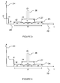
- the figure 4 represents the intensities of the different light pulses as a function of time (the scales are not respected).
- the abscissas 23 represent the time and the ordinates 24 represent the intensity of the light pulses.
- the duration t4 during which the pre-expansion circuit 8 is energized is between the duration t2 during which the continuous supply circuit 6 is energized, and the duration t3, during which a light pulse 26 or a series of main light pulses 26 is generated.
- the end ionized flow between the anode 2 and the cathode 3 of the discharge lamp 1 is generated one second before and one second after the light prepulse 27 of duration t4 '.
- the duration t3 of main light pulses 26, during which a main light pulse 26 or a series of main light pulses 26 is generated can be between 4 ⁇ s and 500 ⁇ s (expandable).
- Each flash or main light pulse 26 can have a fast rise time, less than 2 microseconds.
- the duration of a main light pulse 26 in a prior art flashgun generator is about 5 to 6 microseconds.
- the duration of a main light pulse 26 in a light flash generator according to the invention is about 4 ⁇ s to 500 ⁇ s.
- the number of main light pulses 26 can be programmed from 1 to 100,000 shots per sequence.
- the duration t4 ', during which the light prepulse 27 is generated, depends on the number of main light pulses 26.
- the position in time of the main light pulses 26 with respect to the light prepulse 27 is important.
- the "Simmer” mode is turned on about one second before the "pre-expansion” mode is put into operation.
- the “Simmer” mode remains active 1 s after the duration t4 ', that is to say after the mode in "pre-expansion”.
- the light prepulse 27 can vary between 70 ⁇ s and 80 ⁇ s before and after the duration t3.
- the pre-expansion circuit 8 is supplied by the current 14 to allow the formation of a preheated plasma between the anode 2 and the cathode 3 of the discharge lamp 1.
- the pre-expansion circuit 8 comprises a power supply 9 able to deliver the current of intensity of about 400 milliamps under a voltage V4 of between 250 volts and 1000 volts.
- the intensity 14 of the light prepulse 27 is between 50 amperes and 100 amperes, preferably equal to 80 amperes.
- the pre-expansion circuit 8 comprises a switching means 10 connected in series with the power supply 9 of the pre-expansion circuit and a protection diode 11 connected in series with the switching means 10 and the power supply 9 of the circuit. pre-expansion.
- the protection diode 11 is able to prevent the return of the electrical energy to the supply 9 of the pre-expansion circuit.
- the prepulsed light 27 generated by the pre-expansion circuit 8 helps to overcome temporal fluctuations and reduce the delay between the boot and the flash or series of flashes.
- the plasma is preheated because it is already expanded. It is then ready to receive by switching of the switching means 18 of the main discharge circuit 7, the main discharge which will provide the main light pulse 26.
- the discharge line 17 which is composed of a series of inductive and capacitive elements makes it possible to adjust the duration of the light pulse, to provide a voltage of between 3 KV and 6 KV, preferably 5 KV, and electrical energy. up to 5 kJ / s, at an intensity of about 2000 amperes
- the discharge line 17 makes it possible to obtain an increase in the intensity of the main light pulse 26 up to its maximum value, which is faster. After reaching its maximum value, the intensity of the main light pulse 26 also decreases more rapidly.
- the ideal square shape of the main light pulse 26 is represented on the figure 3 .
- the discharge line 17 provides a main light pulse duration of about 4 to 500 ⁇ s extensible.
- the delay between the priming and the flash (or "jitter") of the set is reduced to a few nano-seconds whatever the discharge lamp 1 used.
- the use of a light prepulse 27 makes it possible to reduce, or even eliminate, the uncertainty between the main electric discharge and the main light pulse 26. transient between them is controlled by the maintenance of an ionized current, between the anode 2 and the cathode 3 of the discharge lamp 1, of greater intensity than the ionized current in "Simmer" mode.
- the behavior of the plasma is close to that of a hot, more stable plasma.
- the light flash generator also comprises a standby circuit 12 connected between the anode 2 and the cathode 3 of the discharge lamp 1. It is capable of providing a standby voltage V5 and a standby current 15 to the discharge lamp 1 continuously. Voltage V5 and intensity I5 are lower than voltage V2 and intensity 12 respectively.
- the standby circuit 12 comprises a power supply 13 capable of enabling the standby circuit 12 to deliver the current of intensity I5 under the voltage V5.
- the standby voltage V5 and the standby intensity can reach up to 3000 volts and 15 milliamps respectively.
- the idle circuit 12 comprises a switching means 14 connected in series with the power supply of the idle circuit 13, and a protection diode 15 connected in series with the switching means 14 and the power supply of the idle circuit 13.
- the protection diode 15 is capable of preventing the return of electrical energy to the power supply of the standby circuit 13.
- the figure 3 represents the intensities of the different light signals as a function of time for a light flash generator having a standby circuit 12.
- the discharge lamp 1 is fed continuously. A very thin ion flow 28 is then generated between the anode 2 and the cathode 3 of the discharge lamp 1.
- the electrical energy necessary to maintain this very thin ion flow 28 is less important than that which is necessary to maintain the ion flow 25 in "Simmer" mode.
- the discharge lamp 1 is fed continuously by the standby circuit 12 before, after operation in "Simmer” mode and for the duration of the application.
- the operation in standby mode maintains a plasma with a behavior close to cold plasmas and contributes to increasing the longevity of the discharge lamp 1.
- the very thin ion flow 28 is initiated by the ignition circuit 5 of the discharge lamp 1 which provides an electrical ignition pulse 5 '.
- a single electrical initiation pulse 5 ' is sufficient for the entire duration of operation of the flash lamp.
- the light flash generator is provided with a means of synchronization by a programmable circuit which makes it possible to position in time, very precisely, the main light pulse 26 with respect to an external standard logic level order.
- the assembly is coordinated by the synchronization means which operates in standard logic and is realized by FPGA programmable circuits ("Field Programmable Gate Array”) or CPLD ("Complex Programmable Logic Device”).
- FPGA programmable circuits Field Programmable Gate Array
- CPLD Complex Programmable Logic Device
- the synchronization means makes it possible to obtain the remote initiation of the discharge lamp 1, the timing and the timing of the electrical signals delivering the pre-pulses and the main electrical discharges, the control of the remote voltages, their reading, their display.
- the synchronization means also makes it possible to obtain external synchronizations, the security of the assembly by detection of faults such as overloads and overheating.
- the light flash generator may include interfaces that provide external control of the various devices (slot scanning cameras, multichannel optical analyzer, shutter systems, for example).
- a light flash generator generating light pulses 26 of high power and each having a fast rise time, less than 2 microseconds.
- the generated light pulses 26 also have a very high reproducibility in time and energy and can be delivered at frequencies up to 50 Hz or even 100 Hz.
- the light flash generator generates all the signals necessary to obtain light flashes for all models of gas lamps of various shapes and structures.
- the light flash generator generates light pulses 26 having a stable and reproducible light plateau in duration, of specified energy.
- the number of light pulses 26 in a series of light pulses 26 depends on the parameters imposed by the user in his field of application which are: the number of light pulses per second, their duration, the repetition frequency, the energy, the power.
- the frequency of recurrence, while taking into account the admissible energy of the tube used can vary from the single shot up to 125 hertz, or even up to 1 Khz.
- the light flash generator provides other benefits.
- the lifespan of the flashlamps is extended by a factor of 1000 compared to the flashlamps of the prior art, with the consequence of a longer spectral fidelity.
- the response time of the light flash generator is extremely accurate.
- the rise time of the light pulse is faster to reach the maximum intensity (about 1.5 microseconds).
- the light flash generator produces stable light pulses calibrated over time.
- the light flash generator is designed according to the strict observance of the rules of construction of electromagnetic compatibility. It is able to operate in a disturbed environment (pulsed laser, accelerator) and it does not produce parasites.
- the discharge lamp used in the light flash generator may be a xenon discharge lamp, krypton or the like.
- the invention also relates to an optical absorption spectrophotometer comprising such a light flash generator.
- the light flash generator is intended to serve as an analysis light for optical absorption spectrophotometry measurements whose detector is a streak-camera.
- the optical absorption spectrophotometer can detect light variations with a temporal resolution of up to 3.7 picoseconds.
- the rise time of each flash is very short (at least less than 2 microseconds), which makes it possible not to saturate the photodetector before measuring the absorption. Under such conditions, it is then possible to record, with the slit-scan camera, the evolution of the absorption spectra in a medium, as a function of time, from the picosecond domain to the microsecond see the millisecond.
- the use of the light flash generator, according to the invention brings a considerable time saving in the collection of results, but also a saving on the operation of the various apparatus of which those producing is accelerating the electrons, and finally the possibility of studying biological systems that do not support too much radiation.
- the light flash generator can also be used in other fields such as pulsed radiolysis, the design of lasers (pumping of the precise amplifying medium), photography, stroboscopy, fixed or onboard signaling. , reprography, skin treatment, UVLASER pulsed decontamination, radioimmunoassay, fluorescence photometers, spectroradiometers, liquid or gas phase chromatographs, colorimeters and ultraviolet applications.
Abstract
Description
L'invention concerne un générateur de flashs lumineux, un spectromètre d'absorption comprenant un tel générateur et un procédé de génération de flashs lumineux.The invention relates to a light flash generator, an absorption spectrometer comprising such a generator and a method for generating light flashes.
Les générateurs de flashs lumineux comprennent habituellement une lampe à décharge, communément appelée lampe flash, capable d'émettre des impulsions lumineuses à une fréquence de répétition de plusieurs dizaines de hertz.The light flash generators usually comprise a discharge lamp, commonly called a flash lamp, capable of emitting light pulses at a repetition frequency of several tens of hertz.
Les lampes flash Xénon (bulbes ou tubes), par exemple, émettent de grandes quantités d'énergie spectrale dans des impulsions de courte durée. L'énergie d'alimentation s'accumule dans un condensateur de stockage. Quand cette énergie est libérée et dissipée, elle forme un plasma xénon hautement excité dans la lampe à décharge. L'énergie libérée couvre une gamme spectrale étendue de l'ultraviolet (UV) à l'infrarouge (IR), ressemblant fortement à la lumière du soleil.For example, Xenon flash bulbs (bulbs or tubes) emit large amounts of spectral energy in short pulses. The power supply accumulates in a storage capacitor. When this energy is released and dissipated, it forms a highly excited xenon plasma in the discharge lamp. The released energy covers an extended spectral range from ultraviolet (UV) to infrared (IR), strongly resembling sunlight.
L'impulsion lumineuse intense d'énergie radiante est utilisée dans de nombreuses applications : arrêt de mouvement, pompage laser, polymérisation UV de polymères, décapage de peinture, et tout particulièrement comme source spectrale stable pour des mesures d'absorption ou de fluorescence.The intense luminous pulse of radiant energy is used in many applications: movement stop, laser pumping, UV polymer polymerization, paint stripping, and especially as a stable spectral source for absorption or fluorescence measurements.
Un tel générateur de flashs lumineux peut servir de lumière d'analyse pour des mesures de spectrophotométrie d'absorption optique dont le détecteur peut être une caméra à balayage de fente (« streak-camera »), comme par exemple, sur l'une des trois aires expérimentales sur lesquelles est distribué le faisceau d'électrons produit par l'accélérateur « ELYSE » du Laboratoire de Chimie Physique de l'Université Paris-Sud.Such a light flash generator can serve as an analysis light for optical absorption spectrophotometry measurements, the detector of which can be a streak-camera, for example, on one of the three experimental areas on which is distributed the electron beam produced by the accelerator "ELYSE" of the Laboratory of Physical Chemistry of the University Paris-Sud.
Les systèmes de détection par spectrophotométrie d'absorption optique de l'art antérieur ne sont pas efficaces pour enregistrer les spectres d'absorption transitoires d'espèces chimiques instables, produites par le passage d'un faisceau d'électrons dans des échantillons, ainsi que l'évolution avec le temps de ces spectres à toutes les longueurs d'ondes.Optical absorption spectrophotometry detection systems of the prior art are not effective for recording the transient absorption spectra of unstable chemical species produced by the passage of an electron beam in samples, as well as the evolution over time of these spectra at all wavelengths.
Ces systèmes de mesure de l'art antérieur ne permettent d'enregistrer soit qu'un seul spectre d'absorption à un temps donné, soit l'évolution du spectre avec le temps, mais à une seule longueur d'onde, par des méthodes de mesures point par point à des temps différents. Les mesures point par point à des temps différents sont ensuite recombinées pour obtenir une évolution temporelle du spectre complet.These measurement systems of the prior art can record either a single absorption spectrum at a given time, or the evolution of the spectrum over time, but at a single wavelength, by methods point-by-point measurements at different times. Point-by-point measurements at different times are then recombined to obtain a temporal evolution of the complete spectrum.
Ces méthodes de l'art antérieur nécessitent un grand nombre d'irradiation des échantillons, ce qui dans certains cas leur est néfaste. Par ailleurs, dans le domaine de l'analyse temporelle, ces sytèmes de détection ne couvrent pas les temps compris entre 2 et 10 nanosecondes.These methods of the prior art require a large number of irradiation of the samples, which in some cases is harmful to them. Moreover, in the field of In time analysis, these detection systems do not cover times between 2 and 10 nanoseconds.
Les générateurs de flashs lumineux actuels comprennent un condensateur de stockage d'énergie chargé qui est normalement connecté aux deux électrodes principales (nommées "anode" et "cathode") de la lampe à décharge. La tension de charge du condensateur est généralement inférieure à celle qui provoque l'ionisation du xénon. Le processus qui provoque l'ionisation initiale est appelé « déclenchement » ou « amorçage » (ou « Triggering »). L'amorçage crée un gradient de tension (Volts/mm) dans le gaz, d'amplitude suffisante pour provoquer l'ionisation.Current light flash generators include a charged energy storage capacitor that is normally connected to the two main electrodes (called "anode" and "cathode") of the discharge lamp. The charge voltage of the capacitor is generally lower than that which causes the ionization of xenon. The process that causes the initial ionization is called "triggering" or "booting" (or "triggering"). Priming creates a voltage gradient (Volts / mm) in the gas, of sufficient magnitude to cause ionization.
La plupart des méthodes d'amorçage utilisent un transformateur d'amorçage pour produire des impulsions haute tension de courte durée. L'ionisation, qui est mise en évidence par un fin sillage lumineux entre les électrodes principales, crée un chemin conducteur au travers duquel peut se décharger le condensateur de stockage d'énergie. Au fur et à mesure que le niveau d'ionisation augmente, l'écoulement augmente en section et produit un flash intense.Most bootstrapping methods use a bootstrap transformer to produce short-lived high-voltage pulses. Ionization, which is evidenced by a thin luminous wake between the main electrodes, creates a conductive path through which the energy storage capacitor can be discharged. As the ionization level increases, the flow increases in section and produces intense flash.
Ces lampes flashs nécessitent un grand nombre d'amorçage (un amorçage par flash), ce qui est un facteur principal de détérioration des lampes à décharge. La durée de vie de ces lampes flashs est très courte.These flashlamps require a large number of priming (flash firing), which is a major factor in the deterioration of discharge lamps. The life of these flashlights is very short.
Pour l'augmenter, il est connu d'utiliser une impulsion d'amorçage initial unique, préalable à toute séquence de flashs, pour provoquer un écoulement ionisé fin entre l'anode et la cathode : c'est le régime « Simmer ». L'écoulement ionisé est entretenu par un courant très faible (quelques dizaines de milliampères). Il est assuré par une alimentation variable (pour tout type de lampe) de 500 à 3000 Volts sous 60 milliampères. On n'utilise qu'un seul amorçage pour une grande série de flashs.To increase it, it is known to use a single initial priming pulse, prior to any sequence of flashes, to cause a fine ionized flow between the anode and the cathode: this is the "Simmer" regime. The ionized flow is maintained by a very low current (a few tens of milliamperes). It is provided by a variable power supply (for any type of lamp) from 500 to 3000 volts under 60 milliamps. Only one boot is used for a large series of flashes.
Le régime « Simmer » permet de multiplier la durée de vie d'une lampe à décharge par un facteur 100 à 1000.The "Simmer" mode allows to multiply the service life of a discharge lamp by a factor of 100 to 1000.
Néanmoins, pendant le fonctionnement en régime « Simmer » la lampe à décharge a un comportement proche des plasmas froids. Un courant imposé plus fort est lent à s'établir. Avec l'élévation de l'intensité de courant, le gaz dans la lampe à décharge tend à devenir un plasma chaud aux propriétés électrocinétiques différentes.Nevertheless, during operation in "Simmer" mode, the discharge lamp has a behavior close to cold plasmas. A stronger imposed current is slow to establish. With the rise of the current intensity, the gas in the discharge lamp tends to become a hot plasma with different electrokinetic properties.
Dishington et Goncz ont proposé deux modèles comportementaux pour comprendre ces deux types de fonctionnement. Ils ont mis en évidence que le passage de l'un à l'autre de ces fonctionnements se fait par une zone instable qui est la cause de fluctuations importantes lors du déclenchement de la décharge principale.Dishington and Goncz proposed two behavioral models to understand these two types of functioning. They highlighted that the transition from one to the other of these operations is done by an unstable zone which is the cause of large fluctuations during the triggering of the main discharge.
Le délai entre l'amorçage et le flash (ou délai de réponse de la lampe à décharge), communément appelé « jitter », est un délai de nature aléatoire entre l'ordre et son effet. Ce délai entre l'amorçage et le flash ou « jitter » provient d'une incertitude de temps entre l'impulsion électrique et l'impulsion lumineuse. Le régime transitoire entre l'impulsion électrique et l'impulsion lumineuse est habituelement incontrôlable. Le délai entre l'amorçage et le flash est compté, dans le meilleur des cas le plus souvent entre 200 ns et 5 µs (microsecondes), avec des éclateurs et suivant le type de lampe à décharge. Et dans le cas d'utilisation de commutateurs classiques, ce délai est de l'ordre de 100 à 200 ns et dépend de la tension à commuter.The delay between the initiation and the flash (or response time of the discharge lamp), commonly called "jitter", is a delay of a random nature between the order and its effect. This delay between the initiation and the flash or "jitter" comes from a time uncertainty between the electric pulse and the light pulse. The transient state between the electric pulse and the light pulse is usually uncontrollable. The delay between the boot and the flash is counted, in the best case most often between 200 ns and 5 μs (microseconds), with gaps and depending on the type of discharge lamp. And in the case of using conventional switches, this delay is of the order of 100 to 200 ns and depends on the voltage to be switched.
Un des objectifs de la présente invention est donc de proposer un générateur de flashs lumineux et un procédé de génération de flashs lumineux permettant d'obtenir une fréquence de répétition des impulsions lumineuses de plusieurs dizaines ou centaines de hertz avec une puissance variable pouvant être très élevée, et un délai entre l'amorçage et le flash reproductible et très faible (inférieur à 10 nano-secondes).One of the objectives of the present invention is therefore to propose a light flash generator and a method for generating light flashes making it possible to obtain a repetition frequency of the light pulses of several tens or hundreds of hertz with a variable power that can be very high. , and a delay between priming and reproducible flash and very low (less than 10 nano-seconds).
Un autre objectif de la présente invention est également de proposer un spectromètre d'absorption permettant d'enregistrer des spectres d'absorption avec une résolution temporelle allant jusqu'à 3,7 picosecondes.Another object of the present invention is also to provide an absorption spectrometer for recording absorption spectra with a temporal resolution of up to 3.7 picoseconds.
A cet effet, l'invention concerne un générateur de flashs lumineux comprenant :
- une lampe à décharge, apte à recevoir des impulsions électriques et à générer des impulsions lumineuses, et comportant trois électrodes dont une anode, une cathode et une électrode d'amorçage,
- un circuit d'alimentation en continu de la lampe à décharge apte à produire une tension V2 et un courant d'intensité I2, entre l'anode et la cathode, pendant une durée t2,
- un circuit d'amorçage de la lampe à décharge apte à fournir une impulsion électrique d'amorçage d'intensité I1 et de tension V1 sur l'électrode d'amorçage de la lampe à décharge, générant entre autre, un peu avant et un peu après les flashs lumineux, un écoulement ionisé fin d'intensité I2, entre l'anode et la cathode, pendant une durée t2',
- un circuit de décharge principale relié entre l'anode et la cathode de la lampe à décharge, ledit circuit de décharge principale étant apte à stocker et à décharger l'énergie électrique nécessaire pour générer une ou plusieurs décharges électriques d'intensité I3, sous une tension V3, dans la lampe à décharge, produisant une impulsion lumineuse ou une série d'impulsions lumineuses principales pendant une durée t3 inférieure à la durée t2', l'intensité 13 et la tension V3 étant supérieures à l'intensité I2 et à la tension V2 respectivement.
- a discharge lamp, adapted to receive electrical pulses and to generate light pulses, and comprising three electrodes including an anode, a cathode and a priming electrode,
- a continuous supply circuit of the discharge lamp capable of producing a voltage V2 and a current of intensity I2, between the anode and the cathode, for a duration t2,
- an ignition circuit of the discharge lamp capable of supplying an electrical ignition pulse of intensity I1 and voltage V1 on the discharge lamp initiation electrode, generating among others, a little before and a little after the light flashes, a thin ionized flow of intensity I2, between the anode and the cathode, for a duration t2 ',
- a main discharge circuit connected between the anode and the cathode of the discharge lamp, said main discharge circuit being able to store and discharge the electrical energy necessary to generate one or more electric discharges of intensity I3, under a voltage V3, in the discharge lamp, producing a light pulse or series of main light pulses for a time t3 less than the duration t2 ', the
intensity 13 and the voltage V3 being greater than the intensity I2 and the voltage V2 respectively.
Selon l'invention, le générateur de flashs lumineux comprend un circuit de pré-expansion relié entre l'anode et la cathode de la lampe à décharge, ledit circuit de pré-expansion étant apte à générer une préimpulsion électrique d'intensité I4, sous une tension V4, dans la lampe à décharge, après la génération de l'écoulement ionisé fin d'intensité I2 et avant la génération d'une ou plusieurs impulsions lumineuses principales dans la lampe à décharge, générant une préimpulsion lumineuse dans la lampe à décharge pendant une durée t4', la durée t4' de la préimpulsion lumineuse étant comprise entre les durées t2' et t3, la tension V4 étant comprise entre les tensions V2 et V3, et apte à permettre la formation d'un plasma préchauffé entre l'anode et la cathode de la lampe à décharge.According to the invention, the light flash generator comprises a pre-expansion circuit connected between the anode and the cathode of the discharge lamp, said pre-expansion circuit being able to generate an electric prepulse of intensity I4, under a voltage V4, in the discharge lamp, after the generation of the I2 end-of-intensity ionized flow and before the generation of one or more main light pulses in the discharge lamp, generating a light pre-pulse in the discharge lamp during a period t4 ', the duration t4' of the light prepulse being between the durations t2 'and t3, the voltage V4 being between voltages V2 and V3, and adapted to allow the formation of a preheated plasma between the anode and the cathode of the discharge lamp.
La préimpulsion permet de s'affranchir des fluctuations ou incertitudes temporelles entre la décharge électrique principale et l'impulsion lumineuse principale, c'est-à-dire entre l'ordre et son effet. Le plasma étant préchauffé, car il est déjà expansé, il est prêt à recevoir par commutation la décharge principale qui fournira l'impulsion lumineuse principale.Prepulse makes it possible to overcome temporal fluctuations or uncertainties between the main electric discharge and the main light pulse, that is to say between the order and its effect. The plasma being preheated because it is already expanded, it is ready to receive by switching the main discharge which will provide the main light pulse.
Le délai entre l'amorçage et le flash (ou « jitter ») de l'ensemble est réduit à quelques nano-secondes quelque soit la lampe à décharge utilisée.The delay between the priming and the flash (or "jitter") of the set is reduced to a few nano-seconds whatever the discharge lamp used.
Dans différents modes de réalisation possibles, la présente invention concerne également les caractéristiques suivantes qui pourront être considérées isolément ou selon toutes leurs combinaisons techniquement possibles et apportent chacune des avantages spécifiques :
- le circuit de pré-expansion comprend :
- o une alimentation variable apte à délivrer un courant d'intensité d'environ 400 milliampères sous une tension comprise entre 250 volts et 1000 volts, l'intensité I4 de la préimpulsion lumineuse étant comprise entre 50 ampères et 100 ampères,
- o un moyen de commutation monté en série avec l'alimentation du circuit de pré-expansion,
- o une diode de protection montée en série avec le moyen de commutation et l'alimentation du circuit de pré-expansion, ladite diode de protection étant apte à empêcher le retour de l'énergie électrique vers l'alimentation du circuit de pré-expansion,
- le générateur de flashs lumineux comprend un circuit de veille relié entre l'anode et la cathode de la lampe à décharge, ledit circuit de veille étant apte à fournir une tension de veille V5 et un courant de veille I5 à la lampe à décharge de façon continue, lorsque le courant I2 est coupé, générant un écoulement ionique très fin entre l'anode et la cathode de la lampe à décharge, la tension V5 et l'intensité I5 étant inférieures à la tension V2 et à l'intensité I2 respectivement,
- le circuit de veille comprend :
- o une alimentation apte à permettre au circuit de veille de délivrer le courant d'intensité I5 sous la tension V5, la tension de veille V5 et l'intensité de veille I5 pouvant atteindre jusqu'à 3000 volts et 15 milliampères respectivement,
- o un moyen de commutation monté en série avec l'alimentation du circuit de veille,
- o une diode de protection montée en série avec le moyen de commutation et l'alimentation du circuit de veille, ladite diode de protection étant apte à empêcher le retour de l'énergie électrique vers l'alimentation du circuit de veille,
- le circuit de décharge principale comprend :
- o une alimentation principale apte à permettre au circuit de décharge principale de délivrer de l'énergie électrique sous le courant d'intensité I3 et la tension V3, l'intensité 13 et la tension V3 étant d'environ 10 kA et 5 kV respectivement,
- o une ligne à décharge montée en parallèle avec l'alimentation principale et la lampe à décharge, ladite ligne à décharge étant composée d'une série d'éléments inductifs et capacitifs, et étant apte à stocker l'énergie électrique fournie par l'alimentation principale et à la décharger dans la lampe à décharge,
- o un moyen de commutation monté en série avec la ligne à décharge et la lampe à décharge, ledit moyen de commutation étant apte à bloquer ou à rendre passant l'énergie électrique stockée dans la ligne à décharge,
- o une diode de protection montée en série avec la lampe à décharge, la ligne à décharge et le moyen de commutation, ladite diode de protection étant apte à empêcher le retour de l'énergie électrique vers la ligne à décharge,
- le circuit d'alimentation en continu comprend :
- o une alimentation apte à délivrer un courant d'intensité d'environ 60 milliampères sous une tension comprise entre 500 volts et 3000 volts, l'intensité I2 entre l'anode et la cathode de la lampe à décharge étant de quelques dizaines de milliampères,
- o une résistance montée en série avec l'alimentation du circuit d'alimentation en continu,
- le générateur de flashs lumineux comprend un moyen de synchronisation tel un circuit programmable,
- le circuit de décharge principale comprend des éléments selfiques,
- les moyens de commutation des différents circuits sont des commutateurs à l'état solide.
- the pre-expansion circuit comprises:
- a variable power supply capable of delivering a current of intensity of approximately 400 milliamps at a voltage of between 250 volts and 1000 volts, the intensity I4 of the light pre-pulse being between 50 amperes and 100 amperes,
- a switching means connected in series with the supply of the pre-expansion circuit,
- a protection diode connected in series with the switching means and the supply of the pre-expansion circuit, said protection diode being able to prevent the return of the electrical energy to the power supply of the pre-expansion circuit,
- the light flash generator comprises a standby circuit connected between the anode and the cathode of the discharge lamp, said standby circuit being capable of supplying a standby voltage V5 and a standby current I5 to the discharge lamp so as to continuous, when the current I2 is cut off, generating a very fine ion flow between the anode and the cathode of the discharge lamp, the voltage V5 and the intensity I5 being lower than the voltage V2 and the intensity I2 respectively,
- the standby circuit includes:
- a power supply capable of enabling the standby circuit to deliver the current of intensity I5 under the voltage V5, the standby voltage V5 and the standby current I5 of up to 3000 volts and 15 milliamps respectively,
- a switching means connected in series with the power supply of the standby circuit,
- a protection diode connected in series with the switching means and the power supply of the standby circuit, said protective diode being able to prevent the return of electrical energy to the power supply of the standby circuit,
- the main discharge circuit comprises:
- a main power supply capable of enabling the main discharge circuit to deliver electrical energy under the current of intensity I3 and the voltage V3, the current 13 and the voltage V3 being approximately 10 kA and 5 kV respectively,
- a discharge line connected in parallel with the main power supply and the discharge lamp, said discharge line being composed of a series of inductive and capacitive elements, and being able to store the electrical energy supplied by the power supply; principal and discharge it into the discharge lamp,
- switching means connected in series with the discharge line and the discharge lamp, said switching means being able to block or to turn on the electrical energy stored in the discharge line,
- a protection diode connected in series with the discharge lamp, the discharge line and the switching means, said protection diode being able to prevent the return of the electrical energy towards the discharge line,
- the continuous feed circuit comprises:
- a power supply capable of delivering a current of intensity of about 60 milliamps at a voltage of between 500 volts and 3000 volts, the intensity I2 between the anode and the cathode of the discharge lamp being a few tens of milliamperes,
- a resistor connected in series with the supply of the continuous supply circuit,
- the light flash generator comprises a synchronization means such as a programmable circuit,
- the main discharge circuit comprises inductive elements,
- the switching means of the different circuits are solid-state switches.
L'invention concerne également un procédé de génération de flashs lumineux par un générateur de flashs lumineux comprenant une lampe à décharge comportant trois électrodes dont une anode, une cathode et une électrode d'amorçage, ladite lampe à décharge étant apte à recevoir des impulsions électriques et à générer des impulsions lumineuses, ledit procédé comprenant :
- une étape consistant à délivrer une tension V2 entre l'anode et la cathode de la lampe à décharge, pendant une durée t2,
- une étape de génération d'une impulsion électrique d'amorçage d'intensité I1 et de tension V1 sur l'électrode d'amorçage de la lampe à décharge, générant entre autre, un peu avant et un peu après les flashs lumineux, un écoulement ionisé fin d'intensité I2, entre l'anode et la cathode, pendant une durée t2',
- une étape de stockage de l'énergie électrique nécessaire pour générer une ou plusieurs décharges électriques d'intensité 13, sous une tension V3, dans la lampe à décharge,
- une étape de décharge de ladite énergie électrique nécessaire pour générer une ou plusieurs décharges électriques dans la lampe à décharge, produisant une impulsion lumineuse ou une série d'impulsions lumineuses principales pendant une durée t3, inférieure à la durée t2', l'intensité I3 et la tension V3 étant supérieures à l'intensité I2 et à la tension V2 respectivement.
- a step of delivering a voltage V2 between the anode and the cathode of the discharge lamp, for a duration t2,
- a step of generating an electrical ignition pulse of intensity I1 and voltage V1 on the ignition electrode of the discharge lamp, generating among others, a little before and a little after the light flashes, a flow ionized end of intensity I2, between the anode and the cathode, for a duration t2 ',
- a step of storing the electrical energy necessary to generate one or more electric discharges of
intensity 13, under a voltage V3, in the discharge lamp, - a step of discharging said electrical energy necessary to generate one or more electric discharges in the discharge lamp, producing a light pulse or a series of main light pulses for a duration t3, less than the duration t2 ', the intensity I3 and the voltage V3 being greater than the intensity I2 and the voltage V2 respectively.
Selon l'invention, le procédé de génération de flashs lumineux comprend :
- une étape de génération d'une préimpulsion électrique d'intensité 14, sous une tension V4, dans la lampe à décharge, après la génération de l'écoulement ionisé fin d'intensité I2, après établissement du régime Simmer, et avant la génération d'une ou plusieurs impulsions lumineuses principales dans la lampe à décharge, générant une préimpulsion lumineuse dans la lampe à décharge pendant une durée t4', la durée t4' de la préimpulsion lumineuse étant comprise entre les durées t2' et t3, la tension V4 étant comprise entre les tensions V2 et V3, et apte à permettre la formation d'un plasma préchauffé entre l'anode et la cathode de la lampe à décharge.
- a step of generating an electric pre-pulse of
intensity 14, under a voltage V4, in the discharge lamp, after the generation of the ionized flow end of intensity I2, after establishment of the Simmer regime, and before the generation of one or more main light pulses in the discharge lamp, generating a light prepulse in the discharge lamp for a time t4 ', the duration t4' of the light prepulse being between the durations t2 'and t3, the voltage V4 being between the voltages V2 and V3, and adapted to allow the formation of a preheated plasma between the anode and the cathode of the discharge lamp.
On obtient ainsi un générateur de flashs lumineux générant des impulsions lumineuses de haute puissance et ayant chacune un temps de montée rapide, inférieur à 2 microsecondes. Les impulsions lumineuses générées ont également une reproductibilité dans le temps et en énergie très élevée et peuvent être délivrées à des fréquences allant jusqu'à 50 Hz, voire 100 Hz.This produces a generator of light flashes generating light pulses of high power and each having a rapid rise time, less than 2 microseconds. The generated light pulses also have a very high reproducibility in time and energy and can be delivered at frequencies up to 50 Hz or even 100 Hz.
Ce générateur de flashs lumineux génère tous les signaux nécessaires à l'obtention de flashs lumineux pour tous modèles de lampes à gaz de structures et de formes diverses.This light flash generator generates all the necessary signals to obtain flashes of light for all models of gas lamps of various shapes and structures.
Le générateur de flashs lumineux génère des impulsions lumineuses ayant un plateau de lumière stable et reproductible en durée, d'énergie spécifiée.The light flash generator generates light pulses having a stable and reproducible light plateau in duration, of specified energy.
La fréquence de récurrence, tout en tenant compte de l'énergie admissible du tube utilisé peut varier du coup unique jusqu'à 125 hertz, voire jusqu'à 1 Khz.The frequency of recurrence, while taking into account the admissible energy of the tube used can vary from the single shot up to 125 hertz, or even up to 1 Khz.
Le générateur de flashs lumineux procure d'autres avantages. La durée de vie des lampes flashs est prolongée d'un facteur 1000 par rapport aux lampes flashs de l'art antérieur, avec pour conséquence une fidélité spectrale plus étendue dans le temps.The light flash generator provides other benefits. The lifespan of the flashlamps is extended by a factor of 1000 compared to the flashlamps of the prior art, with the consequence of a longer spectral fidelity.
Le temps de réponse du générateur de flashs lumineux est d'une extrême précision.The response time of the light flash generator is extremely accurate.
Une grande économie d'énergie est réalisée et la zone utile de l'impulsion lumineuse est plus rapidement atteinte et plus rapidement quittée.A great saving of energy is realized and the useful zone of the luminous pulse is more quickly reached and more quickly left.
Le temps de montée de l'impulsion lumineuse est plus rapide pour atteindre l'intensité maximale (environ 1,5 microsecondes).The rise time of the light pulse is faster to reach the maximum intensity (about 1.5 microseconds).
Le générateur de flashs lumineux produit des impulsions lumineuses stables et calibrées dans le temps.The light flash generator produces stable light pulses calibrated over time.
L'intensité maximale est doublée par rapport à l'intensité maximale obtenue avec des générateurs de flashs lumineux de l'art antérieur.The maximum intensity is doubled with respect to the maximum intensity obtained with light flash generators of the prior art.
L'invention concerne également un spectromètre d'absorption comprenant une caméra à balayage de fente.The invention also relates to an absorption spectrometer comprising a slit scanning camera.
Selon l'invention, le spectromètre d'absorption comprend un générateur de flashs lumineux tel que défini précédemment.According to the invention, the absorption spectrometer comprises a light flash generator as defined above.
Un tel spectrophotomètre d'absorption optique permet de détecter des variations de lumière avec une résolution temporelle allant jusqu'à 3,7 picosecondes. Le temps de montée de chaque flashs est très court (au moins inférieur à 2 microsecondes), ce qui permet de ne pas saturer le photodétecteur avant la mesure de l'absorption. Dans de telles conditions, il est alors possible d'enregistrer, avec la caméra à balayage de fente, l'évolution des spectres d'absorption dans un milieu, en fonction du temps, depuis le domaine de la picoseconde, jusqu'à la microseconde voir la milliseconde.Such an optical absorption spectrophotometer makes it possible to detect light variations with a temporal resolution of up to 3.7 picoseconds. The rise time of each flash is very short (at least less than 2 microseconds), which makes it possible not to saturate the photodetector before measuring the absorption. Under such conditions, it is then possible to record, with the slit-scan camera, the evolution of the absorption spectra in a medium, as a function of time, from the picosecond domain to the microsecond see the millisecond.
Avec un tel spectromètre, il est possible d'enregistrer, avec une résolution temporelle allant jusqu'à 3,7 picosecondes, les spectres d'absorption transitoires d'espèces chimiques instables, produites par le passage d'un faisceau d'électrons dans des échantillons, ainsi que l'évolution avec le temps de ces spectres à toutes les longueurs d'onde.With such a spectrometer, it is possible to record, with a temporal resolution of up to 3.7 picoseconds, the transient absorption spectra of unstable chemical species, produced by the passage of an electron beam in samples, as well as the evolution over time of these spectra at all wavelengths.
L'utilisation du générateur de flashs lumineux, selon l'invention apporte un gain de temps considérable dans la collecte des résultats, mais aussi une économie sur le fonctionnement des différents appareillages dont ceux produisant et accélérant les électrons, et enfin la possibilité d'étudier des systèmes biologiques qui ne supportent pas de trop grande dose d'irradiation.The use of the light flash generator, according to the invention brings a considerable time saving in the collection of results, but also a saving on the operation of the various devices including those producing and accelerating the electrons, and finally the possibility of studying biological systems that do not support too much radiation.
L'invention sera décrite plus en détail en référence aux dessins annexés dans lesquels :
- La
figure 1 représente un générateur de flashs lumineux, de l'art antérieur, apte à fonctionner en mode « Simmer » ; - La
figure 2 représente un générateur de flashs lumineux, selon un mode de réalisation de l'invention ; - La
figure 3 représente les intensités des différents signaux lumineux en fonction du temps pour un générateur de flashs lumineux ayant un circuit de veille ; - La
figure 4 représente les intensités des différents signaux lumineux en fonction du temps pour un générateur de flashs lumineux sans circuit de veille ; - La
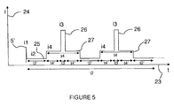
figure 5 représente une succession de flashs lumineux pour un générateur de flashs lumineux sans circuit de veille.
- The
figure 1 represents a light flash generator, of the prior art, able to operate in "Simmer"mode; - The
figure 2 represents a light flash generator, according to an embodiment of the invention; - The
figure 3 represents the intensities of the different light signals as a function of time for a light flash generator having a standby circuit; - The
figure 4 represents the intensities of the different light signals as a function of time for a light flash generator without a standby circuit; - The
figure 5 represents a succession of flashes for a light flash generator without a standby circuit.
La
Le générateur de flashs lumineux de la
Le générateur de flashs lumineux comprend également un circuit d'amorçage 5 de la lampe à décharge apte à fournir une impulsion électrique d'amorçage 5' d'intensité I1 d'environ 200 mA, et de tension V1 de grande amplitude (de l'ordre de 25 kV) sur l'électrode d'amorçage 4 de la lampe à décharge. La génération de l'impulsion électrique d'amorçage 5' permet le passage d'un écoulement ionisé fin 25 entre l'anode 2 et la cathode 3 de la lampe à décharge 1 sous une intensité I2, un peu avant et un peu après les flashs lumineux, pendant une durée t2'. On entend par « écoulement ionisé fin », un flux d'ions de faible section, sous une faible intensité I2.The flashing light generator also comprises a discharge
Le circuit d'alimentation en continu 6 comprend une alimentation 20 apte à délivrer un courant d'intensité d'environ 60 milliampères sous une tension V2 comprise entre 500 volts et 3000 volts. L'intensité I2 entre l'anode 2 et la cathode 3 de la lampe à décharge 1 est de quelques dizaines de milliampères.The
Le circuit d'alimentation en continu 6 peut comprendre une résistance 21 montée en série avec l'alimentation du circuit d'alimentation en continu 20.The
La tension d'alimentation V2 étant déja présente sur l'anode 2 et la cathode 3 de la lampe à décharge 1, le circuit d'amorçage 5 est capable de produire une impulsion haute tension V1 de 25 kV en un temps d'environ 10 microsecondes, sur l'électrode d'amorçage 4 de la lampe à décharge 1. L'ordre d'amorçage qui commande cette impulsion haute tension peut s'effectuer manuellement sur un boitier d'alimentation même, ou bien à distance, en logique standart, associé à une interface isolé galvaniquement à 40 kV.Since the supply voltage V2 is already present on the
Le circuit d'alimentation en continu 6 comprend une alimentation 20 séparée avec des caractéristiques de charge spécifiques, conçue pour que le courant continue de s'écouler dans la lampe à décharge 1 dans un état faible mais stable d'ionisation.The
Le circuit d'alimentation en continu 6 peut comprendre une diode de protection 29 montée en série avec la lampe à décharge 1, et la résistance 21. La diode de protection 29 est apte à empêcher le retour de l'énergie électrique vers l'alimentation 20.The
En mode « Simmer », la lampe à décharge 1 n'a besoin d'être déclenchée qu'une seule fois lors d'une séquence de flashs.In "Simmer" mode, the discharge lamp 1 only needs to be triggered once during a sequence of flashes.
Selon le type de lampe à décharge, le courant « Simmer » I2 typique peut être de quelques dizaines de milliampères jusqu'à plusieurs ampères. La tension V2 aux bornes de la lampe à décharge 1 peut être comprise entre 500 volts et 3000 volts.Depending on the type of discharge lamp, typical "Simmer" I2 current can range from a few tens of milliamperes to several amperes. The voltage V2 across the discharge lamp 1 may be between 500 volts and 3000 volts.
Le générateur de flashs lumineux de la
La durée d'une impulsion lumineuse principale 26 dans un générateur de flashs lumineux de l'art antérieur est d'environ 5 à 6 microsecondes.The duration of a main
Le circuit de décharge principale 7 du générateur de flashs lumineux comprend une alimentation principale 16 apte à délivrer de l'énergie électrique sous le courant d'intensité I3 et la tension V3. L'intensité I3 et la tension V3 sont supérieures à l'intensité 12 et à la tension V2 respectivement.The
Le circuit de décharge principale 7 du générateur de flashs lumineux comprend également une capacité 17' montée en parallèle avec l'alimentation principale 16 et la lampe à décharge 1. La capacité 17' est apte à stocker l'énergie électrique fournie par l'alimentation principale 16 et à la décharger dans la lampe à décharge 1. L'évolution de l'intensité de l'énergie lumineuse au cours du temps suit l'intensité délivrée par la capacité 17', lors de la décharge de cette dernière.The
Le circuit de décharge principale 7 du générateur de flashs lumineux comprend un moyen de commutation 18 monté en série avec la capacité 17' et la lampe à décharge 1. Le moyen de commutation 18 est apte à bloquer ou à rendre passant l'énergie électrique stockée dans la capacité 17'.The
Le circuit de décharge principale 7 du générateur de flashs lumineux comprend une diode de protection 19 montée en série avec la lampe à décharge 1, la capacité 17' et le moyen de commutation 18. La diode de protection 19 est apte à empêcher le retour de l'énergie électrique vers la capacité 17'.The
La
Le générateur de flashs lumineux de la
Le circuit de décharge principale 7 peut comprendre un circuit de mise en forme du type capacitif et selfique. Le circuit de mise en forme peut être un circuit de mise en forme haute tension. L'utilisation de circuits de mise en forme haute tension permet de créer des impulsions lumineuses calibrées et très reproductibles.The
Le moyen de commutation 18 du circuit de décharge principale 7 est mis sous une tension V3 d'environ 5 kV à l'état bloqué et une intensité I3 d'environ 10 kA à l'état passant. Il est commandé en logique standart via un interface isolé galvaniquement à environ 15 kV en continu.The switching means 18 of the
L'énergie de la décharge principale peut être stockée dans un condensateur 17' ou une ligne à décharge 17, et chargée par l'alimentation principale 16 séparée. Ensuite, l'énergie de la décharge principale peut être commutée dans la lampe à décharge 1. Le moyen de commutation 18 peut être un thyristor, ou préférentiellement un commutateur semiconducteur. Le gaz dans la lampe à décharge 1 devient hautement plus ionisé, produisant un flash quand l'énergie se dissipe. Le gaz est alors forcé de retourner à l'état « Simmer ».The energy of the main discharge can be stored in a capacitor 17 'or a
Néanmoins, pendant le fonctionnement en régime « Simmer », la lampe à décharge 1 a un comportement proche des plasmas froids. Un courant imposé plus fort est lent à s'établir.Nevertheless, during operation in "Simmer" mode, the discharge lamp 1 has a behavior close to cold plasmas. A stronger imposed current is slow to establish.
Le délai entre l'amorçage et le flash ou « jitter » est alors important. Il est le plus souvent compris entre 200 ns et 5 µs, suivant le type de lampe à décharge. Et dans le cas de commutateurs classiques, il est de l'ordre de 100 à 200 ns.The delay between the boot and the flash or "jitter" is then important. It is most often between 200 ns and 5 μs, depending on the type of discharge lamp. And in the case of conventional switches, it is of the order of 100 to 200 ns.
Pour réduire ce délai, selon le mode de réalisation de l'invention, représenté sur la
La préimpulsion lumineuse 27 est générée après la génération de l'écoulement ionisé fin 25 d'intensité I2 (courant « Simmer ») et avant la génération d'une ou plusieurs impulsions lumineuses principales 26 dans la lampe à décharge 1.The
La préimpulsion lumineuse 27 peut également continuer à être générée après la génération des impulsions lumineuses principales 26 pendant une durée équivalente à la durée t4', comme représenté sur la
Pendant la génération des préimpulsions lumineuses 27, le courant d'intensité I2 délivré par le circuit d'alimentation en continu 6 est bloqué par la diode 29 et par le fait que la tension V4 est supérieure à la tension V2.During the generation of the
Pendant la génération des impulsions lumineuses principales 26, le courant d'intensité 14 est bloqué par la diode 11 et par le fait que la tension V3 est supérieure à la tension V4.During the generation of the main
La
Les abscisses 23 représentent le temps et les ordonnées 24 représentent l'intensité des impulsions lumineuses.The
La durée t4 pendant laquelle le circuit de pré-expansion 8 est sous tension est comprise entre la durée t2 pendant laquelle le circuit d'alimentation en continu 6 est sous tension, et la durée t3, pendant laquelle une impulsion lumineuse 26 ou une série d'impulsions lumineuses principales 26 est générée.The duration t4 during which the
Pendant la durée t2, l'écoulement ionisé fin 25 entre l'anode 2 et la cathode 3 de la lampe à décharge 1 est généré une seconde avant et une seconde après la préimpulsion lumineuse 27 de durée t4'.During the period t2, the end ionized flow between the
La durée t3 d'impulsions lumineuses principales 26, pendant laquelle une impulsion lumineuse principale 26 ou une série d'impulsions lumineuses principales 26 est générée peut être comprise entre 4 µs et 500 µs (extensible). Chaque flash ou impulsion lumineuse principale 26 peut avoir un temps de montée rapide, inférieur à 2 microsecondes.The duration t3 of main
La durée d'une impulsion lumineuse principale 26 dans un générateur de flashs lumineux de l'art antérieur est d'environ 5 à 6 microsecondes.The duration of a main
La durée d'une impulsion lumineuse principale 26 dans un générateur de flashs lumineux selon l'invention est d'environ 4 µs à 500 µs.The duration of a main
Le nombre d'impulsions lumineuses principales 26 peut être programmé de 1 à 100 000 coups par séquence.The number of main
La durée t4', pendant laquelle la préimpulsion lumineuse 27 est générée, dépend du nombre d'impulsions lumineuses principales 26.The duration t4 ', during which the
La position dans le temps des impulsions lumineuses principales 26 par rapport à la préimpulsion lumineuse 27 est importante. La position optimale entre 70 µs et 80 µs de la décharge par rapport à la préimpulsion lumineuse 27, trouvée expérimentalement, donne un temps de montée de l'impulsion lumineuse principale 26 deux fois plus bref et une amplitude deux fois plus grande par rapport aux temps de montée et amplitudes des impulsions lumineuses de l'art antérieur.The position in time of the main
Le mode « Simmer » est mis en service environ une seconde avant la mise en service du mode en « pré-expansion ». Le mode « Simmer » reste activé 1 s après la durée t4', c'est-à-dire après le mode en « pré-expansion ». Pendant la durée t4', la préimpulsion lumineuse 27 peut varier entre 70 µs et 80 µs avant et après la durée t3.The "Simmer" mode is turned on about one second before the "pre-expansion" mode is put into operation. The "Simmer" mode remains active 1 s after the duration t4 ', that is to say after the mode in "pre-expansion". During the time t4 ', the
Comme illustré sur la
Le circuit de pré-expansion 8 comprend une alimentation 9 apte à délivrer le courant d'intensité d'environ 400 milliampères sous une tension V4 comprise entre 250 volts et 1000 volts. L'intensité 14 de la préimpulsion lumineuse 27 est comprise entre 50 ampères et 100 ampères, de préférence égale à 80 ampères.The
Le circuit de pré-expansion 8 comprend un moyen de commutation 10 monté en série avec l'alimentation 9 du circuit de pré-expansion et une diode de protection 11 montée en série avec le moyen de commutation 10 et l'alimentation 9 du circuit de pré-expansion. La diode de protection 11 est apte à empêcher le retour de l'énergie électrique vers l'alimentation 9 du circuit de pré-expansion.The
La préimpulsion lumineuse 27 générée par le circuit de pré-expansion 8 aide à s'affranchir des fluctuations temporelles et à réduire le délai entre l'amorçage et le flash ou la série de flashs. Le plasma est préchauffé car il est déjà expansé. Il est alors prêt à recevoir par commutation du moyen de commutation 18 du circuit de décharge principale 7, la décharge principale qui fournira l'impulsion lumineuse principale 26.The prepulsed light 27 generated by the
Celle-ci est obtenue à l'aide d'une ligne à décharge 17 du circuit de décharge principale 7 qui remplace le condensateur ou capacité 17' de l'art antérieur (
La ligne à décharge 17 permet d'obtenir une montée de l'intensité de l'impulsion lumineuse principale 26 jusqu'à sa valeur maximale, plus rapide. Après avoir atteint sa valeur maximale, l'intensité de l'impulsion lumineuse principale 26 baisse également plus rapidement. La forme idéale carré de l'impulsion lumineuse principale 26 est représentée sur la
La ligne à décharge 17 permet d'obtenir une durée d'impulsion lumineuse principale d'environ 4 à 500 µs extensible.The
Le délai entre l'amorçage et le flash (ou « jitter ») de l'ensemble est réduit à quelques nano-secondes quelque soit la lampe à décharge 1 utilisée. L'utilisation d'une préimpulsion lumineuse 27 permet de réduire, voire éliminer, l'incertitude entre la décharge électrique principale et l'impulsion lumineuse principale 26. Le régime transitoire entre ces derniers est contrôlé par le maintient d'un courant ionisé, entre l'anode 2 et la cathode 3 de la lampe à décharge 1, d'intensité plus importante que celle du courant ionisé en régime « Simmer ». Le comportement du plasma se rapproche de celui d'un plasma chaud, plus stable.The delay between the priming and the flash (or "jitter") of the set is reduced to a few nano-seconds whatever the discharge lamp 1 used. The use of a
Dans un autre mode de réalisation de l'invention possible, le générateur de flashs lumineux comprend également un circuit de veille 12 relié entre l'anode 2 et la cathode 3 de la lampe à décharge 1. Il est capable de fournir une tension de veille V5 et un courant de veille 15 à la lampe à décharge 1 de façon continue. La tension V5 et l'intensité I5 sont inférieures à la tension V2 et à l'intensité 12 respectivement.In another embodiment of the possible invention, the light flash generator also comprises a
Le circuit de veille 12 comprend une alimentation 13 apte à permettre au circuit de veille 12 de délivrer le courant d'intensité I5 sous la tension V5. La tension de veille V5 et l'intensité de veille 15 peuvent atteindre jusqu'à 3000 volts et 15 milliampères respectivement.The
Le circuit de veille 12 comprend un moyen de commutation 14 monté en série avec l'alimentation du circuit de veille 13, et une diode de protection 15 montée en série avec le moyen de commutation 14 et l'alimentation du circuit de veille 13. La diode de protection 15 est capable d'empêcher le retour de l'énergie électrique vers l'alimentation du circuit de veille 13.The
La
La lampe à décharge 1 est alimentée en continu. Un très fin écoulement ionique 28 est alors généré entre l'anode 2 et la cathode 3 de la lampe à décharge 1. L'énergie électrique nécessaire pour maintenir ce très fin écoulement ionique 28 est moins importante que celle qui est nécessaire à maintenir l'écoulement ionique 25 en mode « Simmer ». La lampe à décharge 1 est alimentée en continu par le circuit de veille 12 avant, après le fonctionnement en mode « Simmer » et pendant toute la durée de l'application.The discharge lamp 1 is fed continuously. A very
Le fonctionnement en mode veille permet d'entretenir un plasma ayant un comportement proche des plasmas froids et participe à augmenter la longévité de la lampe à décharge 1.The operation in standby mode maintains a plasma with a behavior close to cold plasmas and contributes to increasing the longevity of the discharge lamp 1.
Comme représenté sur la
Une seule impulsion électrique d'amorçage 5' suffit pour toute la durée de fonctionnement de la lampe flash.A single electrical initiation pulse 5 'is sufficient for the entire duration of operation of the flash lamp.
Pendant le fonctionnement en mode veille, le courant 12 est coupé, ainsi que les courants I4 et I3.During operation in standby mode, current 12 is turned off, as are currents I4 and I3.
Par exemple, il peut s'écouler trois jours entre deux flashs lumineux. Le fonctionnement en mode veille est alors activé entre ces deux flashs lumineux.For example, it can take three days between two flashes of light. The operation in standby mode is then activated between these two light flashes.
Le générateur de flashs lumineux est pourvu d'un moyen de synchronisation par un circuit programmable qui permet de positionner dans le temps, de façon très précise, l'impulsion lumineuse principale 26 par rapport à un ordre de niveau logique standard extérieur.The light flash generator is provided with a means of synchronization by a programmable circuit which makes it possible to position in time, very precisely, the main
Il est possible de commander localement ou à distance les flashs lumineux 26 et de les synchroniser sur des dispositifs externes (systèmes électro-optiques tels que obturateurs, caméra à balayage de fente, analyseur optique multicanaux, caméras hautes vitesses, etc...) avec un temps de réponse extrêmement précis et très stable.It is possible to control locally or remotely the
L'ensemble est coordonné par le moyen de synchronisation qui fonctionne en logique standard et est réalisé par des circuits programmables FPGA (« Field Programmable Gate Array ») ou CPLD (« Complex Programmable Logic Device »).The assembly is coordinated by the synchronization means which operates in standard logic and is realized by FPGA programmable circuits ("Field Programmable Gate Array") or CPLD ("Complex Programmable Logic Device").
Le moyen de synchronisation permet d'obtenir l'amorçage à distance de la lampe à décharge 1, le cadencement et la temporisation des signaux électriques délivrant les préimpulsions et les décharges électriques principales, le contrôle des tensions à distance, leur lecture, leur affichage.The synchronization means makes it possible to obtain the remote initiation of the discharge lamp 1, the timing and the timing of the electrical signals delivering the pre-pulses and the main electrical discharges, the control of the remote voltages, their reading, their display.
Le moyen de synchronisation permet également d'obtenir les synchronisations externes, la sécurité de l'ensemble par détection de défauts comme les surcharges et les échauffements excessifs.The synchronization means also makes it possible to obtain external synchronizations, the security of the assembly by detection of faults such as overloads and overheating.
Le générateur de flashs lumineux peut comprendre des interfaces qui assurent la commande extérieure des divers appareils (caméras à balayage de fente, analyseur optique multicanaux, systèmes d'obturation, par exemple).The light flash generator may include interfaces that provide external control of the various devices (slot scanning cameras, multichannel optical analyzer, shutter systems, for example).
On obtient ainsi un générateur de flashs lumineux générant des impulsions lumineuses 26 de haute puissance et ayant chacune un temps de montée rapide, inférieur à 2 microsecondes. Les impulsions lumineuses 26 générées ont également une reproductibilité dans le temps et en énergie très élevée et peuvent être délivrées à des fréquences allant jusqu'à 50 Hz, voire 100 Hz.There is thus obtained a light flash generator generating
Le générateur de flashs lumineux, selon l'invention, génère tous les signaux nécessaires à l'obtention de flashs lumineux pour tous modèles de lampes à gaz de structures et de formes diverses.The light flash generator, according to the invention, generates all the signals necessary to obtain light flashes for all models of gas lamps of various shapes and structures.
Le générateur de flashs lumineux génère des impulsions lumineuses 26 ayant un plateau de lumière stable et reproductible en durée, d'énergie spécifiée.The light flash generator generates
Le nombre d'impulsions lumineuses 26 dans une série d'impulsions lumineuses 26 (ou la durée t3) dépend des paramètres imposés par l'utilisateur dans son domaine d'application qui sont : le nombre d'impulsions lumineuses par seconde, leur durée, la fréquence de répétition, l'énergie, la puissance.The number of
La fréquence de récurrence, tout en tenant compte de l'énergie admissible du tube utilisé peut varier du coup unique jusqu'à 125 hertz, voire jusqu'à 1 Khz.The frequency of recurrence, while taking into account the admissible energy of the tube used can vary from the single shot up to 125 hertz, or even up to 1 Khz.
Le générateur de flashs lumineux procure d'autres avantages. La durée de vie des lampes flashs est prolongée d'un facteur 1000 par rapport aux lampes flashs de l'art antérieur, avec pour conséquence une fidélité spectrale plus étendue dans le temps.The light flash generator provides other benefits. The lifespan of the flashlamps is extended by a factor of 1000 compared to the flashlamps of the prior art, with the consequence of a longer spectral fidelity.
Le temps de réponse du générateur de flashs lumineux est d'une extrême précision.The response time of the light flash generator is extremely accurate.
Une grande économie d'énergie est réalisée et la zone utile de l'impulsion lumineuse est plus rapidement atteinte et plus rapidement quittée.A great saving of energy is realized and the useful zone of the luminous pulse is more quickly reached and more quickly left.
Le temps de montée de l'impulsion lumineuse est plus rapide pour atteindre l'intensité maximale (environ 1,5 microsecondes).The rise time of the light pulse is faster to reach the maximum intensity (about 1.5 microseconds).
Le générateur de flashs lumineux produit des impulsions lumineuses stables et calibrées dans le temps.The light flash generator produces stable light pulses calibrated over time.
On obtient une intensité maximale doublée par rapport à l'intensité maximale obtenue avec des générateurs de flashs lumineux de l'art antérieur.A maximum intensity doubled with respect to the maximum intensity obtained with light flash generators of the prior art.
Le générateur de flashs lumineux est conçu suivant la stricte observance des règles de construction de compatibilité électromagnétique. Il est apte à fonctionner en milieu perturbé (laser pulsé, accélérateur) et il ne produit pas de parasites.The light flash generator is designed according to the strict observance of the rules of construction of electromagnetic compatibility. It is able to operate in a disturbed environment (pulsed laser, accelerator) and it does not produce parasites.
La lampe à décharge utilisée dans le générateur de flashs lumineux peut être une lampe à décharge au xénon, krypton ou autre.The discharge lamp used in the light flash generator may be a xenon discharge lamp, krypton or the like.
L'invention concerne également un spectrophotomètre d'absorption optique comprenant un tel générateur de flashs lumineux.The invention also relates to an optical absorption spectrophotometer comprising such a light flash generator.
Le générateur de flashs lumineux, selon l'invention, est destiné à servir de lumière d'analyse pour des mesures de spectrophotométrie d'absorption optique dont le détecteur est une caméra à balayage de fente (« streak-camera »). Le spectrophotomètre d'absorption optique permet de détecter des variations de lumière avec une résolution temporelle allant jusqu'à 3,7 picosecondes. Le temps de montée de chaque flashs est très court (au moins inférieur à 2 microsecondes), ce qui permet de ne pas saturer le photodétecteur avant la mesure de l'absorption. Dans de telles conditions, il est alors possible d'enregistrer, avec la caméra à balayage de fente, l'évolution des spectres d'absorption dans un milieu, en fonction du temps, depuis le domaine de la picoseconde, jusqu'à la microseconde voir la milliseconde.The light flash generator, according to the invention, is intended to serve as an analysis light for optical absorption spectrophotometry measurements whose detector is a streak-camera. The optical absorption spectrophotometer can detect light variations with a temporal resolution of up to 3.7 picoseconds. The rise time of each flash is very short (at least less than 2 microseconds), which makes it possible not to saturate the photodetector before measuring the absorption. Under such conditions, it is then possible to record, with the slit-scan camera, the evolution of the absorption spectra in a medium, as a function of time, from the picosecond domain to the microsecond see the millisecond.
Avec un tel spectromètre, il est possible d'enregistrer, avec une résolution temporelle allant jusqu'à 3,7 picosecondes, les spectres d'absorption transitoires d'espèces chimiques instables, produites par le passage d'un faisceau d'électrons dans des échantillons, ainsi que l'évolution avec le temps de ces spectres à toutes les longueurs d'onde.With such a spectrometer, it is possible to record, with a temporal resolution of up to 3.7 picoseconds, the transient absorption spectra of unstable chemical species, produced by the passage of an electron beam in samples, as well as the evolution over time of these spectra at all wavelengths.
Quant aux systèmes de mesure de l'art antérieur, ils ne permettent d'enregistrer soit qu'un seul spectre d'absorption à un temps donné, soit l'évolution du spectre avec le temps, mais à une seule longueur d'onde, par des méthodes de mesures point par point à des temps différents. Les mesures point par point à des temps différents sont ensuite recombinées pour obtenir une évolution temporelle du spectre complet.As for the measurement systems of the prior art, they only make it possible to record either a single absorption spectrum at a given time, or the evolution of the spectrum with time, but at a single wavelength, by point-by-point measurement methods at different times. Point-by-point measurements at different times are then recombined to obtain a temporal evolution of the complete spectrum.
Ces méthodes de l'art antérieur nécessitent un grand nombre d'irradiation des échantillons, ce qui dans certains cas leur est néfaste.These methods of the prior art require a large number of irradiation of the samples, which in some cases is harmful to them.
L'utilisation du générateur de flashs lumineux, selon l'invention apporte un gain de temps considérable dans la collecte des résultats, mais aussi une économie sur le fonctionnement des différents appareillages dont ceux produisant est accélérant les électrons, et enfin la possibilité d'étudier des systèmes biologiques qui ne supportent pas de trop grande dose d'irradiation.The use of the light flash generator, according to the invention brings a considerable time saving in the collection of results, but also a saving on the operation of the various apparatus of which those producing is accelerating the electrons, and finally the possibility of studying biological systems that do not support too much radiation.
Le générateur de flashs lumineux, selon l'invention, peut également être utilisé dans d'autres domaines comme par exemple la radiolyse pulsée, la conception des lasers (pompage du milieu amplificateur précis), la photographie, la stroboscopie, la signalisation fixe ou embarquée, la reprographie, le traitement de la peau, la décontamination UVLASER pulsé, le dosage radio-immunologique, les photomètres de fluorescence, les spectroradiomètres, les chromatographes en phase liquide ou gazeuse, les colorimètres et les applications en ultraviolet.The light flash generator, according to the invention, can also be used in other fields such as pulsed radiolysis, the design of lasers (pumping of the precise amplifying medium), photography, stroboscopy, fixed or onboard signaling. , reprography, skin treatment, UVLASER pulsed decontamination, radioimmunoassay, fluorescence photometers, spectroradiometers, liquid or gas phase chromatographs, colorimeters and ultraviolet applications.
Claims (11)
- A light flash generator characterized in that it includes:- a high-pressure discharge lamp (1), capable of receiving electric pulses and of generating light pulses, and comprising three electrodes (2, 3, 4), including one anode (2), on cathode (3) and one starting electrode (4),- a continuous power supply circuit (6) for the discharge lamp, capable of producing a voltage V2 and a current of intensity I2, the anode (2) and the cathode (3), for a duration t2,- a starting circuit (5) for the discharge lamp (1), capable of providing a starting electric pulse (5') of intensity I1 and voltage V1 on the starting electrode (4) of the discharge lamp, generating, among other things, slightly before and slightly the light flashes, a thin ion flow (25) of intensity I2, between the anode (2) and the cathode (3), for a duration t2',- a pre-expansion circuit (8) connected between the anode (2) and the cathode (3) of the discharge lamp (1), said pre-expansion circuit (8) being capable of generating an electric pre-pulse of intensity I4, under a voltage V4, in the discharge lamp (1), after the generation of the thin ion flow (25) of of intensity I2, and before the generation of one or several main light pulses (26) in the discharge lamp (1), generating a light pre-pulse (27) in the discharge lamp (1) for a duration t4', the duration t4' of the light pre-pulse (27) being comprised the durations t2' and t3, the intensity I4 being comprised the intensities I2 and I3, the voltage V4 being lower than the voltage V3 and higher than the voltage V2, so as to block the current I2, and chosen so as to permit the formation of a pre-heated plasma between the anode (2) and the cathode (3) of the discharge lamp (1),- a main discharge circuit (7) connected between the anode (2) and the cathode (3) of the discharge lamp (1), said main discharge circuit (7) being capable of storing and discharging the electric energy necessary for generating one or several electric discharges of intensity I3, under a voltage V3, in the discharge lamp (1), producing a light pulse or a series of main light pulses (26) for a duration t3 shorter than the duration t2', the intensity 13 being higher than the intensity I2 and the voltage V3 being higher than the voltage V4, so as to block the current I4, the electric pre-pulse continuing to be generated in the discharge lamp (1) after the end of the main light pulses (26), and the thin ion flow (25) continuing to be generated in the discharge lamp (1) after the end of the electric pre-pulse.
- A light flash generator according to claim 1, characterized in that the pre-expansion circuit (8) includes:- a variable power supply (9), capable of delivering a current with an intensity of about 400 milliamperes, under a voltage comprised between 250 volts and 1000 volts, the intensity I4 of the light pre-pulse (27) being comprised between 50 amperes and 100 amperes, preferably equal to 80 amperes,- a switching means (10) mounted series with the power supply (9) of the pre-expansion circuit,- a protection diode (11) mounted in series with the switching means (10) and the power supply (9) of the pre-expansion circuit, said protection diode (11) being capable of preventing the electric from returning toward the power supply (9) of the pre-expansion circuit.
- A light flash generator according to any one of claims 1 or 2, characterized in that it includes a standby circuit (12) connected between the anode (2) and the cathode (3) of the discharge lamp (1), said standby circuit (12) in capable of providing in continuous a standby voltage V5 and a standby current I5 to the discharge lamp (1), when the current I2 is cut-off, generating a very thin ion flow (28) between the anode (2) and the cathode (3) of the discharge lamp (1), the voltage V5 and the intensity 15 being lower than the voltage V2 and the intensity I2, respectively.
- A light flash generator according to claim 3, characterized in that the standby circuit (12) includes:- a power supply (13) capable of allowing the standby circuit (12) to the current of intensity I5 under the voltage V5, the standby voltage V5 and the standby intensity I5 being to reach up to 3000 volts and 15 milliamperes, respectively,- a switching means (14) mounted in series with the power supply of the standby circuit (13),- a protection diode (15) mounted in series with the switching means (14) and the power supply of the standby circuit (13), said protection diode (15) being capable of preventing the electric energy from returning toward the power supply of the standby circuit (13).
- A light flash generator according to any one of claims 1 to 4, characterized in that the main discharge circuit (7) includes:- a main power supply (16) capable of allowing the main discharge circuit (7) to deliver an electric energy under the current of intensity I3 and the voltage V3, the intensity I3 and the voltage V3 being of about 10 kA and 5 KV, respectively,- a discharge line (17) mounted in parallel with the main power supply (16) and the discharge lamp (1), said discharge line (17) being consisted of a series of inductive and capacitive and capable of storing the electric energy provided by the main power supply (16) and of discharging it in the discharge lamp (1),- a switching means (18) mounted in series with the discharge line (17) and the discharge lamp (1), said switching means (18) being capable of blocking or releasing the electric energy stored in the discharge line (17),- a protection diode (19) mounted in series with the discharge lamp (1), the discharge line (17) and the switching means (18), said protection diode (19) in capable of preventing the electric energy from returning toward the discharge line (17).
- A light flash generator according to any of claims 1 to 5, characterized in that the continuous power supply circuit (6) includes:- a power supply (20) capable of delivering a current with an intensity of about 60 milliamperes under a voltage comprised between 500 volts and 3000 volts, the intensity I2 between the anode (2) and the cathode (3) of the discharge lamp (1) being of a few tens of milliamperes,- a resistor (21) mounted in series with the power supply of the continuous power supply circuit (20).
- A light flash generator according to any one of claims 1 to 6, characterized in that it includes a synchronization means such as a programmable circuit.
- A light flash generator according to any one of claims 1 to 7, characterized in that the main discharge circuit (7) includes inductive elements.
- A light flash generator according to any one of claims 1 to 8, characterized in that the switching means (10, 14, 18) of the various circuits (7, 8, 12) are solid-state switches.
- An absorption spectrometer including a strip scan camera characterized in that it includes a light flash generator as defined in any one of claims 1 to 9.
- A method of generating light flashes by a light flash generator including a high-pressure discharge lamp (1) comprising three electrodes (2, 3, 4), including one anode (2), one cathode (3) and one starting electrode (4), said discharge lamp (1) being capable of receiving electric and of generating light pulses, said method being characterized in that it comprises:- a step of delivering a voltage V2 between the anode (2) and the cathode (3) of the discharge lamp (1), for a duration t2,- a step of generating a starting electric pulse (5') of intensity I1 and voltage V1 on the starting electrode (4) of the discharge lamp, generating, among other things, slightly before and slightly after the light flashes, a thin ion flow (25) of intensity I2, between the anode (2) and the cathode (3), for a duration t2',- a step of storing the energy necessary for generating one or several electric discharges on intensity I3, under a voltage V3, in the discharge lamp (1),- a step of generating an electric pre-pulse of intensity I4, under a voltage V4, in the discharge lamp (1), the generation of the thin ion flow (25) of intensity I2, and before the generation of one or several main light pulses (26) in the discharge lamp (1), generating a light pre-pulse (27) in the discharge lamp (1) for a duration t4', the duration t4' of the light pre-pulse (27) being comprised between the durations t2' and t3, the intensity I4 being comprised between the intensities I2 and I3, the voltage V4 being lower than the voltage V3 and higher than the voltage V2, so as to block the current 12, and chosen so as to permit the formation of a pre-heated plasma between the anode (2) and the cathode (3) of the discharge lamp (1),- a step of discharging said electric energy necessary for generating one or several electric discharges in the discharge lamp (1), producing a light pulse or a series of main light pulses (26) for a duration t3 shorter than the duration t2', the intensity I3 being higher than the intensity I2 and the voltage V3 being higher than the voltage V4, so as to block the current I4, the electric pre-pulse continuing to be generated in the discharge lamp (1) after the end of the main light pulses (26), and the thin ion flow (25) continuing to be generated in the discharge lamp (1) after the end of the electric pre-pulse.
Applications Claiming Priority (2)
| Application Number | Priority Date | Filing Date | Title |
|---|---|---|---|
| FR0850457A FR2926948B1 (en) | 2008-01-24 | 2008-01-24 | LUMINOUS FLASH GENERATOR, ABSORPTION SPECTROMETER USING SUCH A GENERATOR AND METHOD FOR GENERATING LIGHT FLASKS |
| PCT/FR2009/050082 WO2009095584A1 (en) | 2008-01-24 | 2009-01-21 | Light flash generator, absorption spectrometer including such generator, and method for generating light flashes |
Publications (2)
| Publication Number | Publication Date |
|---|---|
| EP2243339A1 EP2243339A1 (en) | 2010-10-27 |
| EP2243339B1 true EP2243339B1 (en) | 2012-06-06 |
Family
ID=39521904
Family Applications (1)
| Application Number | Title | Priority Date | Filing Date |
|---|---|---|---|
| EP09706899A Active EP2243339B1 (en) | 2008-01-24 | 2009-01-21 | Light flash generator, absorption spectrometer including such generator, and method for generating light flashes |
Country Status (3)
| Country | Link |
|---|---|
| EP (1) | EP2243339B1 (en) |
| FR (1) | FR2926948B1 (en) |
| WO (1) | WO2009095584A1 (en) |
Families Citing this family (4)
| Publication number | Priority date | Publication date | Assignee | Title |
|---|---|---|---|---|
| FR2980665B1 (en) * | 2011-09-23 | 2013-10-25 | Centre Nat Rech Scient | ELECTRIC APPARATUS FOR PRIMING A FLASH LAMP, AND ELECTRIC OPTICAL PUMPING SYSTEM COMPRISING SUCH A STARTING APPARATUS |
| LT5957B (en) * | 2011-12-16 | 2013-08-26 | Uab "Ekspla" | Method of controlling the current of flash lamp |
| CN107006109B (en) * | 2014-11-14 | 2019-10-18 | 保富图公司 | Flash generator for flash tube |
| EP3624564A1 (en) * | 2018-09-13 | 2020-03-18 | Rovak GmbH | Method and assembly for flash lamp control |
Family Cites Families (6)
| Publication number | Priority date | Publication date | Assignee | Title |
|---|---|---|---|---|
| US5144146A (en) * | 1990-07-06 | 1992-09-01 | Ultraviolet Energy Generators, Inc. | Method for destruction of toxic substances with ultraviolet radiation |
| JP2658900B2 (en) * | 1994-09-30 | 1997-09-30 | 日本電気株式会社 | Pulse power supply |
| JP4107532B2 (en) * | 1999-01-12 | 2008-06-25 | ミヤチテクノス株式会社 | Laser equipment |
| US20020149326A1 (en) * | 2001-03-01 | 2002-10-17 | Mikhail Inochkin | Flashlamp drive circuit |
| FR2867347B1 (en) * | 2003-03-03 | 2015-08-07 | Eurofeedback Sa | TUBE WITH LIGHTS |
| FR2852189B1 (en) * | 2003-03-03 | 2005-08-05 | Eurofeedback Sa | METHOD, GENERATOR AND LIGHT TUBE FOR GENERATING UVC |
-
2008
- 2008-01-24 FR FR0850457A patent/FR2926948B1/en not_active Expired - Fee Related
-
2009
- 2009-01-21 EP EP09706899A patent/EP2243339B1/en active Active
- 2009-01-21 WO PCT/FR2009/050082 patent/WO2009095584A1/en active Application Filing
Also Published As
| Publication number | Publication date |
|---|---|
| WO2009095584A1 (en) | 2009-08-06 |
| EP2243339A1 (en) | 2010-10-27 |
| FR2926948A1 (en) | 2009-07-31 |
| FR2926948B1 (en) | 2012-11-02 |
Similar Documents
| Publication | Publication Date | Title |
|---|---|---|
| Manschwetus et al. | Two-photon double ionization of neon using an intense attosecond pulse train | |
| EP2243339B1 (en) | Light flash generator, absorption spectrometer including such generator, and method for generating light flashes | |
| Mehr et al. | Trigger devices for pseudospark switches | |
| FR2615324A1 (en) | ION PLASMA ELECTRON CANNON AND METHOD FOR PR ODUCING SECONDARY ELECTRONS FROM SUCH A CANNON | |
| US6541924B1 (en) | Methods and systems for providing emission of incoherent radiation and uses therefor | |
| US5216482A (en) | Apparatus for emission spectrochemical analysis | |
| KR20160035616A (en) | Flashlamp degradation monitoring system and method | |
| EP0064003B1 (en) | Device for the pulsed electron beam processing of a specimen | |
| FR2578378A1 (en) | FLASHLIGHT DEVICE | |
| Goltsov et al. | Is efficiency of gain generation in Li III 13.5-nm laser with 0.25-/spl mu/m subpicosecond pulses the same as with 1/spl mu/m? | |
| US20050218823A1 (en) | Camera flash apparatus using ultraviolet light for triggering of the flash tube | |
| Pouncey et al. | Triggering of pressurized gas switches with a class I laser | |
| EP3703105B1 (en) | Device for generating optimised uv spectrum | |
| Dussart et al. | Time-resolved spatial distribution of an ablative capillary discharge obtained with a pinhole camera | |
| Baryshnikov et al. | Small-sized nanosecond source of powerful wide-band VUV-UV radiation | |
| Itami et al. | An intense, broadband emission spectrum, thyratron‐gated nanosecond light source using a commercially available Xe short‐arc lamp | |
| Adams et al. | Resonant laser-induced breakdown across high voltage gap for air-fuel ignition | |
| Avizonis et al. | Electrical and Spectrographic Study of a Double‐Pulsed Flashtube as applied to Laser Pumping | |
| Schinca et al. | Ionic classification of Xe laser lines: A new approach through time resolved spectroscopy | |
| Meshchanov et al. | An “Anomalous” Effect of Illumination on the Breakdown in a Long Discharge Tube in Xenon | |
| Rybka et al. | Emission characteristics of a pulsed discharge in xenon | |
| Miles et al. | Laser REMPI triggering of an air spark gap with nanosecond jitter | |
| US20120195342A1 (en) | Configuration for Multiwavelength Emission with a CO2 Laser | |
| CA3145386A1 (en) | Pulsed generator of electrically charged particles and method of use of a pulsed generator of electrically charged particles | |
| Okano | Guided discharge path by weakly ionized region between two plasmas produced by YAG laser in an atmospheric air gap with nonuniform DC electric field |
Legal Events
| Date | Code | Title | Description |
|---|---|---|---|
| PUAI | Public reference made under article 153(3) epc to a published international application that has entered the european phase |
Free format text: ORIGINAL CODE: 0009012 |
|
| 17P | Request for examination filed |
Effective date: 20100722 |
|
| AK | Designated contracting states |
Kind code of ref document: A1 Designated state(s): AT BE BG CH CY CZ DE DK EE ES FI FR GB GR HR HU IE IS IT LI LT LU LV MC MK MT NL NO PL PT RO SE SI SK TR |
|
| AX | Request for extension of the european patent |
Extension state: AL BA RS |
|
| DAX | Request for extension of the european patent (deleted) | ||
| GRAP | Despatch of communication of intention to grant a patent |
Free format text: ORIGINAL CODE: EPIDOSNIGR1 |
|
| GRAS | Grant fee paid |
Free format text: ORIGINAL CODE: EPIDOSNIGR3 |
|
| GRAA | (expected) grant |
Free format text: ORIGINAL CODE: 0009210 |
|
| AK | Designated contracting states |
Kind code of ref document: B1 Designated state(s): AT BE BG CH CY CZ DE DK EE ES FI FR GB GR HR HU IE IS IT LI LT LU LV MC MK MT NL NO PL PT RO SE SI SK TR |
|
| REG | Reference to a national code |
Ref country code: GB Ref legal event code: FG4D Free format text: NOT ENGLISH |
|
| REG | Reference to a national code |
Ref country code: AT Ref legal event code: REF Ref document number: 561545 Country of ref document: AT Kind code of ref document: T Effective date: 20120615 Ref country code: CH Ref legal event code: EP |
|
| REG | Reference to a national code |
Ref country code: IE Ref legal event code: FG4D Free format text: LANGUAGE OF EP DOCUMENT: FRENCH |
|
| REG | Reference to a national code |
Ref country code: DE Ref legal event code: R096 Ref document number: 602009007472 Country of ref document: DE Effective date: 20120802 |
|
| REG | Reference to a national code |
Ref country code: NL Ref legal event code: VDEP Effective date: 20120606 |
|
| PG25 | Lapsed in a contracting state [announced via postgrant information from national office to epo] |
Ref country code: SE Free format text: LAPSE BECAUSE OF FAILURE TO SUBMIT A TRANSLATION OF THE DESCRIPTION OR TO PAY THE FEE WITHIN THE PRESCRIBED TIME-LIMIT Effective date: 20120606 Ref country code: CY Free format text: LAPSE BECAUSE OF FAILURE TO SUBMIT A TRANSLATION OF THE DESCRIPTION OR TO PAY THE FEE WITHIN THE PRESCRIBED TIME-LIMIT Effective date: 20120606 Ref country code: NO Free format text: LAPSE BECAUSE OF FAILURE TO SUBMIT A TRANSLATION OF THE DESCRIPTION OR TO PAY THE FEE WITHIN THE PRESCRIBED TIME-LIMIT Effective date: 20120906 Ref country code: LT Free format text: LAPSE BECAUSE OF FAILURE TO SUBMIT A TRANSLATION OF THE DESCRIPTION OR TO PAY THE FEE WITHIN THE PRESCRIBED TIME-LIMIT Effective date: 20120606 Ref country code: FI Free format text: LAPSE BECAUSE OF FAILURE TO SUBMIT A TRANSLATION OF THE DESCRIPTION OR TO PAY THE FEE WITHIN THE PRESCRIBED TIME-LIMIT Effective date: 20120606 |
|
| REG | Reference to a national code |
Ref country code: AT Ref legal event code: MK05 Ref document number: 561545 Country of ref document: AT Kind code of ref document: T Effective date: 20120606 |
|
| REG | Reference to a national code |
Ref country code: LT Ref legal event code: MG4D Effective date: 20120606 |
|
| PG25 | Lapsed in a contracting state [announced via postgrant information from national office to epo] |
Ref country code: SI Free format text: LAPSE BECAUSE OF FAILURE TO SUBMIT A TRANSLATION OF THE DESCRIPTION OR TO PAY THE FEE WITHIN THE PRESCRIBED TIME-LIMIT Effective date: 20120606 Ref country code: HR Free format text: LAPSE BECAUSE OF FAILURE TO SUBMIT A TRANSLATION OF THE DESCRIPTION OR TO PAY THE FEE WITHIN THE PRESCRIBED TIME-LIMIT Effective date: 20120606 Ref country code: GR Free format text: LAPSE BECAUSE OF FAILURE TO SUBMIT A TRANSLATION OF THE DESCRIPTION OR TO PAY THE FEE WITHIN THE PRESCRIBED TIME-LIMIT Effective date: 20120907 Ref country code: LV Free format text: LAPSE BECAUSE OF FAILURE TO SUBMIT A TRANSLATION OF THE DESCRIPTION OR TO PAY THE FEE WITHIN THE PRESCRIBED TIME-LIMIT Effective date: 20120606 |
|
| PG25 | Lapsed in a contracting state [announced via postgrant information from national office to epo] |
Ref country code: SK Free format text: LAPSE BECAUSE OF FAILURE TO SUBMIT A TRANSLATION OF THE DESCRIPTION OR TO PAY THE FEE WITHIN THE PRESCRIBED TIME-LIMIT Effective date: 20120606 Ref country code: NL Free format text: LAPSE BECAUSE OF FAILURE TO SUBMIT A TRANSLATION OF THE DESCRIPTION OR TO PAY THE FEE WITHIN THE PRESCRIBED TIME-LIMIT Effective date: 20120606 Ref country code: IS Free format text: LAPSE BECAUSE OF FAILURE TO SUBMIT A TRANSLATION OF THE DESCRIPTION OR TO PAY THE FEE WITHIN THE PRESCRIBED TIME-LIMIT Effective date: 20121006 Ref country code: RO Free format text: LAPSE BECAUSE OF FAILURE TO SUBMIT A TRANSLATION OF THE DESCRIPTION OR TO PAY THE FEE WITHIN THE PRESCRIBED TIME-LIMIT Effective date: 20120606 Ref country code: CZ Free format text: LAPSE BECAUSE OF FAILURE TO SUBMIT A TRANSLATION OF THE DESCRIPTION OR TO PAY THE FEE WITHIN THE PRESCRIBED TIME-LIMIT Effective date: 20120606 Ref country code: AT Free format text: LAPSE BECAUSE OF FAILURE TO SUBMIT A TRANSLATION OF THE DESCRIPTION OR TO PAY THE FEE WITHIN THE PRESCRIBED TIME-LIMIT Effective date: 20120606 Ref country code: EE Free format text: LAPSE BECAUSE OF FAILURE TO SUBMIT A TRANSLATION OF THE DESCRIPTION OR TO PAY THE FEE WITHIN THE PRESCRIBED TIME-LIMIT Effective date: 20120606 |
|
| PG25 | Lapsed in a contracting state [announced via postgrant information from national office to epo] |
Ref country code: PL Free format text: LAPSE BECAUSE OF FAILURE TO SUBMIT A TRANSLATION OF THE DESCRIPTION OR TO PAY THE FEE WITHIN THE PRESCRIBED TIME-LIMIT Effective date: 20120606 Ref country code: PT Free format text: LAPSE BECAUSE OF FAILURE TO SUBMIT A TRANSLATION OF THE DESCRIPTION OR TO PAY THE FEE WITHIN THE PRESCRIBED TIME-LIMIT Effective date: 20121008 Ref country code: IT Free format text: LAPSE BECAUSE OF FAILURE TO SUBMIT A TRANSLATION OF THE DESCRIPTION OR TO PAY THE FEE WITHIN THE PRESCRIBED TIME-LIMIT Effective date: 20120606 |
|
| PLBE | No opposition filed within time limit |
Free format text: ORIGINAL CODE: 0009261 |
|
| STAA | Information on the status of an ep patent application or granted ep patent |
Free format text: STATUS: NO OPPOSITION FILED WITHIN TIME LIMIT |
|
| PG25 | Lapsed in a contracting state [announced via postgrant information from national office to epo] |
Ref country code: ES Free format text: LAPSE BECAUSE OF FAILURE TO SUBMIT A TRANSLATION OF THE DESCRIPTION OR TO PAY THE FEE WITHIN THE PRESCRIBED TIME-LIMIT Effective date: 20120917 Ref country code: DK Free format text: LAPSE BECAUSE OF FAILURE TO SUBMIT A TRANSLATION OF THE DESCRIPTION OR TO PAY THE FEE WITHIN THE PRESCRIBED TIME-LIMIT Effective date: 20120606 |
|
| 26N | No opposition filed |
Effective date: 20130307 |
|
| REG | Reference to a national code |
Ref country code: DE Ref legal event code: R097 Ref document number: 602009007472 Country of ref document: DE Effective date: 20130307 |
|
| BERE | Be: lapsed |
Owner name: UNIVERSITE PARIS-SUD Effective date: 20130131 |
|
| PG25 | Lapsed in a contracting state [announced via postgrant information from national office to epo] |
Ref country code: BG Free format text: LAPSE BECAUSE OF FAILURE TO SUBMIT A TRANSLATION OF THE DESCRIPTION OR TO PAY THE FEE WITHIN THE PRESCRIBED TIME-LIMIT Effective date: 20120906 |
|
| PG25 | Lapsed in a contracting state [announced via postgrant information from national office to epo] |
Ref country code: MC Free format text: LAPSE BECAUSE OF NON-PAYMENT OF DUE FEES Effective date: 20130131 |
|
| REG | Reference to a national code |
Ref country code: CH Ref legal event code: PL |
|
| REG | Reference to a national code |
Ref country code: IE Ref legal event code: MM4A |
|
| PG25 | Lapsed in a contracting state [announced via postgrant information from national office to epo] |
Ref country code: BE Free format text: LAPSE BECAUSE OF NON-PAYMENT OF DUE FEES Effective date: 20130131 Ref country code: LI Free format text: LAPSE BECAUSE OF NON-PAYMENT OF DUE FEES Effective date: 20130131 Ref country code: CH Free format text: LAPSE BECAUSE OF NON-PAYMENT OF DUE FEES Effective date: 20130131 |
|
| PG25 | Lapsed in a contracting state [announced via postgrant information from national office to epo] |
Ref country code: IE Free format text: LAPSE BECAUSE OF NON-PAYMENT OF DUE FEES Effective date: 20130121 |
|
| PG25 | Lapsed in a contracting state [announced via postgrant information from national office to epo] |
Ref country code: MT Free format text: LAPSE BECAUSE OF FAILURE TO SUBMIT A TRANSLATION OF THE DESCRIPTION OR TO PAY THE FEE WITHIN THE PRESCRIBED TIME-LIMIT Effective date: 20120606 |
|
| PG25 | Lapsed in a contracting state [announced via postgrant information from national office to epo] |
Ref country code: TR Free format text: LAPSE BECAUSE OF FAILURE TO SUBMIT A TRANSLATION OF THE DESCRIPTION OR TO PAY THE FEE WITHIN THE PRESCRIBED TIME-LIMIT Effective date: 20120606 |
|
| PG25 | Lapsed in a contracting state [announced via postgrant information from national office to epo] |
Ref country code: HU Free format text: LAPSE BECAUSE OF FAILURE TO SUBMIT A TRANSLATION OF THE DESCRIPTION OR TO PAY THE FEE WITHIN THE PRESCRIBED TIME-LIMIT; INVALID AB INITIO Effective date: 20090121 Ref country code: LU Free format text: LAPSE BECAUSE OF NON-PAYMENT OF DUE FEES Effective date: 20130121 Ref country code: MK Free format text: LAPSE BECAUSE OF FAILURE TO SUBMIT A TRANSLATION OF THE DESCRIPTION OR TO PAY THE FEE WITHIN THE PRESCRIBED TIME-LIMIT Effective date: 20120606 |
|
| REG | Reference to a national code |
Ref country code: FR Ref legal event code: PLFP Year of fee payment: 8 |
|
| REG | Reference to a national code |
Ref country code: FR Ref legal event code: PLFP Year of fee payment: 9 |
|
| REG | Reference to a national code |
Ref country code: FR Ref legal event code: PLFP Year of fee payment: 10 |
|
| PGFP | Annual fee paid to national office [announced via postgrant information from national office to epo] |
Ref country code: FR Payment date: 20230127 Year of fee payment: 15 |
|
| PGFP | Annual fee paid to national office [announced via postgrant information from national office to epo] |
Ref country code: GB Payment date: 20230127 Year of fee payment: 15 Ref country code: DE Payment date: 20230130 Year of fee payment: 15 |
|
| REG | Reference to a national code |
Ref country code: DE Ref legal event code: R081 Ref document number: 602009007472 Country of ref document: DE Owner name: UNIVERSITE PARIS- SACLAY, FR Free format text: FORMER OWNER: UNIVERSITE PARIS SUD, ORSAY, FR |
|
| REG | Reference to a national code |
Ref country code: GB Ref legal event code: 732E Free format text: REGISTERED BETWEEN 20231123 AND 20231129 |