EP2243191B1 - Resonanzreflektoranordnung und verfahren - Google Patents
Resonanzreflektoranordnung und verfahren Download PDFInfo
- Publication number
- EP2243191B1 EP2243191B1 EP09711020.9A EP09711020A EP2243191B1 EP 2243191 B1 EP2243191 B1 EP 2243191B1 EP 09711020 A EP09711020 A EP 09711020A EP 2243191 B1 EP2243191 B1 EP 2243191B1
- Authority
- EP
- European Patent Office
- Prior art keywords
- reflector
- members
- assembly
- resonant frequency
- electric
- Prior art date
- Legal status (The legal status is an assumption and is not a legal conclusion. Google has not performed a legal analysis and makes no representation as to the accuracy of the status listed.)
- Not-in-force
Links
Images




Classifications
-
- H—ELECTRICITY
- H01—ELECTRIC ELEMENTS
- H01Q—ANTENNAS, i.e. RADIO AERIALS
- H01Q1/00—Details of, or arrangements associated with, antennas
- H01Q1/04—Adaptation for subterranean or subaqueous use
-
- F—MECHANICAL ENGINEERING; LIGHTING; HEATING; WEAPONS; BLASTING
- F41—WEAPONS
- F41J—TARGETS; TARGET RANGES; BULLET CATCHERS
- F41J2/00—Reflecting targets, e.g. radar-reflector targets; Active targets transmitting electromagnetic or acoustic waves
-
- G—PHYSICS
- G01—MEASURING; TESTING
- G01S—RADIO DIRECTION-FINDING; RADIO NAVIGATION; DETERMINING DISTANCE OR VELOCITY BY USE OF RADIO WAVES; LOCATING OR PRESENCE-DETECTING BY USE OF THE REFLECTION OR RERADIATION OF RADIO WAVES; ANALOGOUS ARRANGEMENTS USING OTHER WAVES
- G01S7/00—Details of systems according to groups G01S13/00, G01S15/00, G01S17/00
- G01S7/02—Details of systems according to groups G01S13/00, G01S15/00, G01S17/00 of systems according to group G01S13/00
-
- G—PHYSICS
- G01—MEASURING; TESTING
- G01V—GEOPHYSICS; GRAVITATIONAL MEASUREMENTS; DETECTING MASSES OR OBJECTS; TAGS
- G01V15/00—Tags attached to, or associated with, an object, in order to enable detection of the object
-
- G—PHYSICS
- G06—COMPUTING OR CALCULATING; COUNTING
- G06K—GRAPHICAL DATA READING; PRESENTATION OF DATA; RECORD CARRIERS; HANDLING RECORD CARRIERS
- G06K19/00—Record carriers for use with machines and with at least a part designed to carry digital markings
- G06K19/06—Record carriers for use with machines and with at least a part designed to carry digital markings characterised by the kind of the digital marking, e.g. shape, nature, code
- G06K19/067—Record carriers with conductive marks, printed circuits or semiconductor circuit elements, e.g. credit or identity cards also with resonating or responding marks without active components
- G06K19/07—Record carriers with conductive marks, printed circuits or semiconductor circuit elements, e.g. credit or identity cards also with resonating or responding marks without active components with integrated circuit chips
- G06K19/077—Constructional details, e.g. mounting of circuits in the carrier
- G06K19/07749—Constructional details, e.g. mounting of circuits in the carrier the record carrier being capable of non-contact communication, e.g. constructional details of the antenna of a non-contact smart card
-
- H—ELECTRICITY
- H01—ELECTRIC ELEMENTS
- H01Q—ANTENNAS, i.e. RADIO AERIALS
- H01Q1/00—Details of, or arrangements associated with, antennas
- H01Q1/12—Supports; Mounting means
- H01Q1/22—Supports; Mounting means by structural association with other equipment or articles
-
- H—ELECTRICITY
- H01—ELECTRIC ELEMENTS
- H01Q—ANTENNAS, i.e. RADIO AERIALS
- H01Q1/00—Details of, or arrangements associated with, antennas
- H01Q1/12—Supports; Mounting means
- H01Q1/22—Supports; Mounting means by structural association with other equipment or articles
- H01Q1/2208—Supports; Mounting means by structural association with other equipment or articles associated with components used in interrogation type services, i.e. in systems for information exchange between an interrogator/reader and a tag/transponder, e.g. in Radio Frequency Identification [RFID] systems
- H01Q1/2225—Supports; Mounting means by structural association with other equipment or articles associated with components used in interrogation type services, i.e. in systems for information exchange between an interrogator/reader and a tag/transponder, e.g. in Radio Frequency Identification [RFID] systems used in active tags, i.e. provided with its own power source or in passive tags, i.e. deriving power from RF signal
-
- H—ELECTRICITY
- H01—ELECTRIC ELEMENTS
- H01Q—ANTENNAS, i.e. RADIO AERIALS
- H01Q1/00—Details of, or arrangements associated with, antennas
- H01Q1/27—Adaptation for use in or on movable bodies
- H01Q1/32—Adaptation for use in or on road or rail vehicles
-
- H—ELECTRICITY
- H01—ELECTRIC ELEMENTS
- H01Q—ANTENNAS, i.e. RADIO AERIALS
- H01Q1/00—Details of, or arrangements associated with, antennas
- H01Q1/36—Structural form of radiating elements, e.g. cone, spiral, umbrella; Particular materials used therewith
- H01Q1/38—Structural form of radiating elements, e.g. cone, spiral, umbrella; Particular materials used therewith formed by a conductive layer on an insulating support
-
- H—ELECTRICITY
- H01—ELECTRIC ELEMENTS
- H01Q—ANTENNAS, i.e. RADIO AERIALS
- H01Q15/00—Devices for reflection, refraction, diffraction or polarisation of waves radiated from an antenna, e.g. quasi-optical devices
- H01Q15/14—Reflecting surfaces; Equivalent structures
-
- H—ELECTRICITY
- H01—ELECTRIC ELEMENTS
- H01Q—ANTENNAS, i.e. RADIO AERIALS
- H01Q21/00—Antenna arrays or systems
- H01Q21/24—Combinations of antenna units polarised in different directions for transmitting or receiving circularly and elliptically polarised waves or waves linearly polarised in any direction
-
- H—ELECTRICITY
- H01—ELECTRIC ELEMENTS
- H01Q—ANTENNAS, i.e. RADIO AERIALS
- H01Q25/00—Antennas or antenna systems providing at least two radiating patterns
- H01Q25/001—Crossed polarisation dual antennas
-
- H—ELECTRICITY
- H01—ELECTRIC ELEMENTS
- H01Q—ANTENNAS, i.e. RADIO AERIALS
- H01Q7/00—Loop antennas with a substantially uniform current distribution around the loop and having a directional radiation pattern in a plane perpendicular to the plane of the loop
-
- H—ELECTRICITY
- H01—ELECTRIC ELEMENTS
- H01Q—ANTENNAS, i.e. RADIO AERIALS
- H01Q9/00—Electrically-short antennas having dimensions not more than twice the operating wavelength and consisting of conductive active radiating elements
- H01Q9/04—Resonant antennas
- H01Q9/16—Resonant antennas with feed intermediate between the extremities of the antenna, e.g. centre-fed dipole
-
- G—PHYSICS
- G01—MEASURING; TESTING
- G01S—RADIO DIRECTION-FINDING; RADIO NAVIGATION; DETERMINING DISTANCE OR VELOCITY BY USE OF RADIO WAVES; LOCATING OR PRESENCE-DETECTING BY USE OF THE REFLECTION OR RERADIATION OF RADIO WAVES; ANALOGOUS ARRANGEMENTS USING OTHER WAVES
- G01S13/00—Systems using the reflection or reradiation of radio waves, e.g. radar systems; Analogous systems using reflection or reradiation of waves whose nature or wavelength is irrelevant or unspecified
- G01S13/74—Systems using reradiation of radio waves, e.g. secondary radar systems; Analogous systems
- G01S13/75—Systems using reradiation of radio waves, e.g. secondary radar systems; Analogous systems using transponders powered from received waves, e.g. using passive transponders, or using passive reflectors
-
- G—PHYSICS
- G01—MEASURING; TESTING
- G01S—RADIO DIRECTION-FINDING; RADIO NAVIGATION; DETERMINING DISTANCE OR VELOCITY BY USE OF RADIO WAVES; LOCATING OR PRESENCE-DETECTING BY USE OF THE REFLECTION OR RERADIATION OF RADIO WAVES; ANALOGOUS ARRANGEMENTS USING OTHER WAVES
- G01S13/00—Systems using the reflection or reradiation of radio waves, e.g. radar systems; Analogous systems using reflection or reradiation of waves whose nature or wavelength is irrelevant or unspecified
- G01S13/88—Radar or analogous systems specially adapted for specific applications
- G01S13/885—Radar or analogous systems specially adapted for specific applications for ground probing
-
- G—PHYSICS
- G01—MEASURING; TESTING
- G01S—RADIO DIRECTION-FINDING; RADIO NAVIGATION; DETERMINING DISTANCE OR VELOCITY BY USE OF RADIO WAVES; LOCATING OR PRESENCE-DETECTING BY USE OF THE REFLECTION OR RERADIATION OF RADIO WAVES; ANALOGOUS ARRANGEMENTS USING OTHER WAVES
- G01S13/00—Systems using the reflection or reradiation of radio waves, e.g. radar systems; Analogous systems using reflection or reradiation of waves whose nature or wavelength is irrelevant or unspecified
- G01S13/88—Radar or analogous systems specially adapted for specific applications
- G01S13/93—Radar or analogous systems specially adapted for specific applications for anti-collision purposes
- G01S13/931—Radar or analogous systems specially adapted for specific applications for anti-collision purposes of land vehicles
- G01S2013/9316—Radar or analogous systems specially adapted for specific applications for anti-collision purposes of land vehicles combined with communication equipment with other vehicles or with base stations
-
- G—PHYSICS
- G01—MEASURING; TESTING
- G01S—RADIO DIRECTION-FINDING; RADIO NAVIGATION; DETERMINING DISTANCE OR VELOCITY BY USE OF RADIO WAVES; LOCATING OR PRESENCE-DETECTING BY USE OF THE REFLECTION OR RERADIATION OF RADIO WAVES; ANALOGOUS ARRANGEMENTS USING OTHER WAVES
- G01S7/00—Details of systems according to groups G01S13/00, G01S15/00, G01S17/00
- G01S7/02—Details of systems according to groups G01S13/00, G01S15/00, G01S17/00 of systems according to group G01S13/00
- G01S7/024—Details of systems according to groups G01S13/00, G01S15/00, G01S17/00 of systems according to group G01S13/00 using polarisation effects
- G01S7/025—Details of systems according to groups G01S13/00, G01S15/00, G01S17/00 of systems according to group G01S13/00 using polarisation effects involving the transmission of linearly polarised waves
Definitions
- the present invention relates to resonant radar reflectors and to a method of using resonant radar reflectors.
- the invention relates to identification of an asset using radar reflectors.
- Determining a location and identity of a buried asset can be a challenging task. In some cases, determination of the location is performed by systematically digging holes in ground until the asset is found. In some cases, ground penetrating radar (GPR) is used, assets being identified by a signal reflected by the asset. (Reference to GPR includes radiation having a frequency in the range of from around 200MHz to around 1GHz. Other frequencies are also useful).
- GPR ground penetrating radar
- This technique for locating buries assets suffers the disadvantage that radiation can be reflected by a number of features of a volume of ground, including variations in moisture content, solids composition, the presence of wildlife, and voids formed for example by tunnelling wildlife. Thus it can be difficult to reliably identify a location of a buried asset.
- RFID tag radio frequency identification tag
- Inductive magnetic fields are relatively short range, however, and the use of such RFID tag systems to locate and identify assets more than a few metres from the reader is generally not practical.
- RFID readers are incapable of generating sufficiently large excitation signals to detect RFID tags at required distances below a surface.
- US3769623 discloses a dichroic plate for passing radiation within a particular frequency band and reflecting radiation outside of that frequency band.
- the dichroic plate has slots provided therein dimensioned to pass radiation of a selected frequency.
- US5837926 discloses mines having tuned passive electromagnetic reflectors to enhance radar detection.
- US 3789404 discloses a periodic surface for large scan angles.
- a resonant radar reflector assembly comprising first and second reflector members, the first and second reflector members each being configured to resonate at a respective resonant frequency when irradiated by radio frequency (RF) radiation of a corresponding frequency
- the first member has a portion responsive to an electric field applied parallel to an electric polarisation axis of the first member
- the second member having a corresponding portion responsive to an electric field applied parallel to a corresponding electric polarisation axis of the second member
- the first member also having a portion responsive to a magnetic field applied parallel to a magnetic polarisation axis of the first member
- the second member having a corresponding portion responsive to a magnetic field applied parallel to a corresponding magnetic polarisation axis of the second member
- the first and second members being arranged such that at least one electric or magnetic polarisation axis of the first member is substantially not parallel to the corresponding electric or magnetic polarisation axis of the second member, a resonant frequency of
- Some embodiments of the invention have the advantage that passive identification tags may be provided that can be interrogated from a longer distance than RFID tags relying on interrogation by means of RF inductive fields.
- Embodiments of the invention may be interrogated by a far-field RF signal, such as is used in radar systems.
- corresponding electric polarisation axes are substantially non-parallel or corresponding magnetic polarisation axes are substantially non-parallel a visibility of the assembly to polarised RF radiation such as ground-penetrating radar (GPR) may be enhanced. This is because in the case of a planar assembly (i.e.
- first and second reflector members are substantially coplanar) irradiated by a beam of GPR radiation normal to the plane of the reflector members and parallel to a magnetic polarisation axis of both members, if (say) the electric polarisation axis of the GPR signal is normal to the corresponding electric polarisation axis of one reflector member, the electric polarisation axis of the other reflector member of the assembly will have a component non-parallel to a corresponding electric polarisation axis of the GPR signal. Consequently this other reflector member is likely to reflect at least a portion of the GPR signal, enhancing visibility of the assembly.
- the electric or magnetic polarisation axis of the first member may be substantially orthogonal to the corresponding electric or magnetic polarisation axis of the second member.
- the corresponding electric polarisation axes may be orthogonal to one another and the corresponding magnetic polarisation axes may be parallel to one another or non-parallel to one another.
- a reflector member of an assembly may have more than one axis of electric polarisation and/or more than one axis of magnetic polarisation.
- a resonant frequency of the first member is different to a resonant frequency of the second member, the members being arranged to reflect RF signals of different respective prescribed frequencies.
- This feature has the advantage that RF signals of a plurality of different wavelengths may be reflected by a single assembly, allowing an assembly to be identified by measuring a difference between the resonant frequencies of the two members. This is in contrast to some examples in which both reflector members have the same resonant frequency. In this case, in some embodiments where a further reflector assembly having a reflector member having a different resonant frequency is not present, identification of the reflector assembly may be performed by measurement of the absolute resonant frequency of reflector members of the assembly, or by measurement of the difference between the resonant frequencies of the reflector members of the assembly and that of a reference resonant frequency. In some embodiments this requires interrogation apparatus calibrated to measure absolute values of a reflected signal detected by the interrogation apparatus.
- the feature that two reflector members have different respective resonant frequencies has the further advantage that an identity of a reflector assembly can be determined by reference to the specific frequencies of RF radiation reflected by the assembly, allowing a larger number of assembly identifiers to be developed.
- one assembly may be arranged whereby both members resonate at a frequency f1
- another assembly may be configured whereby both members resonate at a different frequency f2
- a further assembly being configured whereby one member resonates at the frequency f1 and another member resonates at the frequency f2.
- a given assembly may have more than two reflector members and therefore in some such embodiments may have members having three of more members having different respective resonant frequencies.
- the portion of at least one of the first or second members responsive to an electric field comprises a dipole portion.
- This feature has the advantage that a resonant member of increased radar cross-section (RCS) may be provided.
- the dipole portion may comprise a conducting portion having one selected from amongst a substantially straight linear portion, a substantially curved portion, a portion in the form of a meander pattern and a substantially tapered portion.
- the portion of at least one of the reflector members responsive to a magnetic field applied parallel to a magnetic polarisation axis of the member comprises a loop portion.
- the loop portion is a discontinuous loop such that the loop does not define a substantially closed path.
- At least one reflector member comprises a loop portion and a dipole portion.
- the first and second reflector members each comprise a loop portion and a dipole portion.
- At least one reflector member having a dipole portion and a loop portion has a pair of dipole portions, the dipole portions being coupled to respective opposed ends of the loop portion.
- each reflector member comprises a capacitive portion.
- the capacitive portion comprises a pair of substantially parallel conducting elements.
- the loop portion is coupled to the dipole portion by means of the capacitive portion.
- the elements of the capacitive portion may be oriented generally normal to the dipole portion.
- the reflector members are arranged in use to be spaced apart from a conducting surface.
- This feature has the advantage that the conducting surface may provide a 'pick-up' whereby an intensity of a signal reflected by the member is increased.
- the reflector members of the assembly are arranged to be provided in a substantially coplanar configuration.
- the members may be arranged to be provided in an orientation substantially parallel to a plane of the conducting surface.
- the reflector members are arranged to be spaced apart from the conducting surface by means of a dielectric medium.
- the dielectric medium may be provided in the form of a layer of material to which the reflector members are attached.
- the assembly may comprise the conducting surface.
- the conducting surface may be provided by an asset associated with the assembly.
- the assembly may be arranged to be coupled to the asset.
- the portions of the first and second members responsive to an electric field and the portions of the first and second members responsive to a magnetic field comprise electrically conducting portions
- the portions of the first and second members responsive to an electric field and the portions of the first and second members responsive to a magnetic field comprise substantially flat electrically conducting tracks formed on a substrate,
- said portions of the first and second members are formed on a common substrate.
- said portions of the first and second members may be formed on different respective substrates.
- a structure comprising first and second strings of resonant radar reflector members, the first string having the form of a right-handed helix, the second string having the form of a left-handed helix, the first and second strings intersecting one another at at least one intersect position of the structure, the structure providing a reflector assembly according to the first aspect of the invention at one of said at least one intersect positions.
- a reflector member of the first string and a reflector member of the second string located proximate an intersection of the first string with the second string may be arranged to have corresponding axes of electric polarisation or corresponding axes of magnetic polarisation that are generally non-parallel to one another.
- This feature has the advantage that an assembly may be formed in a convenient manner during a process of fabricating the asset and/or applying reflector members to the asset. Other ways of forming assemblies of reflector members may be useful.
- Such a structure may be formed around an asset such as a pipe or any other suitable asset.
- the structure may be supported by the asset.
- reflector members of the structure may be coupled to the asset individually, for example by an adhesive.
- reflector members of the assembly may be coupled to one another, for example by means of a carrier material such as a tape to which the reflector members are attached.
- a reflector member of the first string and a reflector member of the second string located proximate an intersection of the first string with the second string may have corresponding axes of electric polarisation or corresponding axes of magnetic polarisation that are substantially perpendicular to one another.
- This feature has the advantage that detection of reflector members at the intersection may be made substantially independent of a plane of polarisation of electromagnetic radiation used to interrogate a reflector assembly, such as GPR or any other useful form of electromagnetic radiation.
- reflector members of a given string have corresponding axes of electric polarisation or corresponding axes of magnetic polarisation that have a generally fixed angle with respect to a longitudinal axis of the structure, the reflector members being arranged at different respective angular positions about the longitudinal axis.
- a resonant frequency of a reflector member of the first string may be different from a resonant frequency of a reflector member of the second string.
- This feature has the advantage that in some embodiments information concerning a relative orientation of an assembly, and therefore the asset to which the assembly is attached, may be obtained more readily by interrogation apparatus.
- interrogation apparatus is provided and arranged to vary an orientation of a plane of polarisation of a beam of plane-polarised interrogating radiation and to determine an orientation of the assembly by measuring an intensity of a signal reflected by one or more reflector assemblies as a function of orientation of the plane of polarisation.
- the first string comprises a plurality of reflector members each having a resonant frequency of a first value and the second string comprises a plurality of reflector members each having a resonant frequency of a second value different from the first value.
- the reflector members may be arranged in a spatial configuration whereby an identifier of an asset associated with the structure may be determined based on said spatial configuration.
- a first reflector assembly of the structure may comprise a reflector member having a resonant frequency different from a resonant frequency of a reflector member of a second reflector assembly of the structure thereby to provide at least a portion of an identifier of an asset.
- a distance between respective reflector assemblies of the structure may be configured to provide at least a portion of an identifier of the asset.
- interrogation apparatus is arranged to irradiate the assembly with circularly polarised radiation. In some embodiments interrogation apparatus is arranged to irradiate the assembly with unpolarised radiation.
- an asset comprising a structure according to the first example.
- an asset according to the second or third examples comprising a pipe.
- the asset may be buried underground.
- a vehicle having an assembly according to the first aspect provided thereon.
- first and second strings of resonant radar reflector members the first string having the form of a right-handed helix, the second string having the form of a left-handed helix, the first and second strings being arranged to intersect one another at at least one intersect position, the strings providing a reflector assembly according to the first aspect of the invention at the at least one intersect position.
- a resonant frequency of the first reflector member is different from a resonant frequency of the second reflector member, the method further comprising measuring the resonant frequency of the first and second reflector members.
- a resonant frequency of the first reflector member is different from a resonant frequency of the second reflector member and the method further comprises measuring a difference between the resonant frequency of the first reflector member and the resonant frequency of the second reflector member.
- the step of irradiating the assembly with RF radiation may comprise irradiating the assembly with plane polarised RF radiation.
- the method may comprise the step of determining an orientation of a reflector member by changing a plane of polarisation of the plane polarised RF radiation and detecting a signal reflected by said reflector member.
- the method may comprise the step of irradiating the assembly with at least one selected from amongst circularly polarised RF radiation and unpolarised RF radiation.
- identification of an assembly and/or an asset is determined by reference to relative or absolute intensities of signals reflected from one or more reflector members.
- a resonant radar reflector assembly 100 is provided as shown in FIG. 1 .
- the assembly has a pair of resonant radar reflector members 110A, 110B provided on a substrate 102.
- the reflector members 110A, 110B are arranged to reflect radiation in the GPR frequency range, i.e. frequencies less than around 1GHz. Other frequency ranges are also useful.
- Soil in urban areas is a relatively complex environment for electromagnetic propagation.
- Soil typically has inhomogeneous propagation constants, but can be theoretically approximated as a conducting dielectric medium. Depending on the particular soil composition, it may have a large range of dielectric constants and conductivities. These parameters influence the attenuation of radiation propagating therein and the electromagnetic resonance characteristics of devices and structures immersed in the medium.
- a good resonator should ideally have good radiation efficiency, high Q factor, and an identifiable reflection resonance that is relatively insensitive to soil condition, particularly to water content of the soil.
- the reflector members 110A, 110B are arranged generally at right angles to one another. Other configurations are also useful.
- the reflector members 110A, 110B each comprise a loop portion 112A, 112B and a dipole portion 114A, 114B.
- the reflector members 110A, 110B are arranged to resonate at a resonant frequency in response to incident RF radiation of a prescribed frequency. This resonant frequency is determined at least in part by dimensions of the reflector members 110A, 110B.
- the dimensions of interest include the diameter of the loop portion 112A, 112B and the length of the dipole portion 114A, 114B.
- Each of the reflector members 110A, 110B has an axis of electric polarisation generally parallel to a longitudinal axis of the dipole portion 114A, 114B. It is to be understood that polarised electromagnetic radiation having an electric field component polarised generally normal to the electric polarisation axis of one of the reflector members 110A, 110B will generally not cause that reflector member to resonate at an amplitude that is as great as that when the electric field component is polarised generally parallel to the axis of electric polarisation of that reflector member.
- each of the reflector members 110A, 110B has an axis of magnetic polarisation generally normal to a plane of the respective loop portion 112A, 112B. It is to be understood that polarised electromagnetic radiation having a magnetic field component polarised generally normal to the axis of magnetic polarisation of one of the reflector members 110A, 110B will generally not cause that reflector member to resonate at an amplitude that is as great as that when the magnetic field component is polarised generally parallel to the axis of magnetic polarisation of the reflector member.
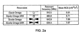
- FIG. 2 shows examples of reflector members according to some embodiments of the invention together with a corresponding resonant frequency.
- Values of mean radar cross-section (RCS) of the reflector members are also listed. It is to be understood that other resonant frequencies are also useful.
- the resonant frequencies of the types of structures shown in FIG. 2 are presented merely as examples of possible frequencies. Similar structures having different resonant frequencies and different values of RCS are also useful.
- FIG. 2(a) The dipole omega resonator structure of FIG. 2(a) is also shown in FIG 2(e) , whilst the bowtie omega of FIG. 2(a) is also shown in FIG. 2(f) .
- a split ring resonator is shown in FIG. 2(c) and forms the loop portion of the dipole omega SRR and bowtie omega SRR structures of FIG. 2(a) .
- a resonator having a spiral ring resonator portion ( FIG. 2(d) ) may be used instead of the ring resonators of FIG. 2(b), (c) .
- the reflector assembly 100 of FIG. 1 is provided with a pair of reflector members 110A, 110B arranged such that their respective axes of electric polarisation are generally orthogonal to one another.
- the reflector members of a reflector assembly are arranged to resonate at substantially the same resonant frequency. In some embodiments the reflector members of a given assembly are arranged to resonate at different respective frequencies.
- FIG. 3 shows a scenario in which an underground asset (a utility pipe 260) has been provided with a reflector assembly 200 according to an embodiment of the invention.
- Interrogation apparatus 280 having a transmitter element 282 and a receiver element 284 has been arranged to transmit an RF signal in the direction of the pipe 260 and to detect a signal reflected by the reflector assembly 200.
- the reflector assembly 200 is provided with a pair of reflector members 210A, 210B having different respective resonant frequencies.
- the interrogation apparatus 280 is arranged to irradiate the reflector assembly with RF radiation of a frequency corresponding to the resonant frequencies of each of the reflector members 210A, 210B in turn.
- an RF signal launched by the transmitter element 282 is arranged to vary in frequency as a function of time in steps of a given frequency.
- the interrogation apparatus measures a time taken for a signal of a frequency corresponding to the transmission frequency to be detected by the receiver element 284 as a signal reflected by a reflector member 284.
- the provision of a pair of reflector members 110A, 110B assists a process of identifying the reflector assembly 200 since the difference between the resonant frequencies of the reflector members, rather than the absolute frequencies themselves, can be measured. Thus, precise calibration of the interrogation apparatus 280 in order to measure absolute frequencies is not required.
- reflector assemblies may be arranged in a spatial configuration unique to that article or class of articles. Different respective spatial configurations may differ in one or more parameters such as a distance between respective assembles of a given configuration, a distance between reflector members of a given assembly and/or the one or more frequencies of RF radiation that a given assembly is arranged to reflect.
- reflector members of a given assembly are not physically coupled or attached to one another, but are separate reflector members that are attached to an asset or positioned close to an asset without being attached to the asset.
- FIG. 4(a) shows a pipe having four reflector assemblies 301, 302, 303, 304 provided thereon.
- the reflector assemblies are substantially equally spaced apart along the pipe. In some embodiments the reflector assemblies are not substantially equally spaced apart along the pipe.
- the assemblies are arranged in a configuration whereby a resonant frequency of at least one of the assemblies is different from a resonant frequency of at least one other of the assemblies.
- the resonant frequency of elements 301, 303 and 304 may be of a first value whilst the resonant frequency of element 302 may be of a second value different from the first value.
- Configurations in which three or more assemblies are provided each having a different respective resonant frequency are also useful.
- the assemblies may be arranged whereby a particular combination of resonant frequency and location of respective assemblies provides an identifier of the asset.
- the assemblies are arranged in a combination whereby a spatial separation of adjacent assemblies along the length of the pipe is characteristic of the pipe, providing an identifier of the pipe.
- a spatial separation of adjacent assemblies 305, 306 is a distance d1
- a separation of adjacent assemblies 306, 307 is a distance d2
- a separation of adjacent assemblies 307, 308 is a distance d3
- the combination of respective values of d1, d2 and d3 providing the unique identifier.
- an identifier of a pipe is provided by a combination of a value of a resonant frequency of an assembly and a value of a distance between one or more pairs of assemblies.
- an identifier of a pipe is provided by the number of assemblies of a given group of assemblies.
- respective groups of assemblies are separated by a prescribed distance whereby a number of assemblies of a given group may be determined, such as two, three, four, five or more assemblies of as given group.
- members of a given group of assemblies each have substantially the same resonant frequency or pair of resonant frequencies.
- assemblies at ends of the linear configuration may be arranged to reflect radiation of one or more prescribed frequencies to aid identification of a given group.
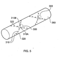
- FIG. 5 shows a further embodiment of the invention in which a pipe 360 has been provided with two strings of reflector members 320, 322 in a substantially helical arrangement around the pipe 360.
- the two strings are of left-handed and right-handed orientation, respectively.
- Mutually adjacent reflector members 310 within a given string are arranged to have their axes of polarisation generally mutually co-linear with one another along a helical path.
- a reflector assembly 300 is provided at an intersection of the respective strings of reflector members, an assembly being provided by reflector members 310A and 310B of respective different strings.
- helical wrapping of reflector members according to some embodiments of the invention around an asset such as a pipe in the manner indicated generally in FIG. 5 is useful in providing means for identifying an asset.
- Such wrapping provides identification from which a useful reflected signal may be obtained by interrogation apparatus substantially independently of a direction of polarisation of RF radiation generated by the interrogation apparatus. This is at least in part because the reflector members are arranged to have a plurality of respective different orientations.
- coupling between adjacent reflector members can enhance a magnitude of a signal reflected by a given reflector member.
- strings of reflector members are introduced to the pipe during a process of forming the pipe, for example following or during a process of extrusion of the pipe.
- FIG. 6 shows an embodiment of the invention in which a motor vehicle 401 has been fitted with a reflector assembly 400 according to an embodiment of the invention.
- a further vehicle 402 has been fitted with interrogation apparatus 480 according to an embodiment of the invention, the interrogation apparatus 480 being arranged to detect a reflector assembly 400 of the kind fitted to vehicle 401.
- Detection of the assembly 400 by interrogation apparatus 480 can be used to trigger an alert to a driver of vehicle 402.
- a controller in vehicle 402 is configured to measure a relative speed of vehicles 401, 402 and to provide an alert in the event that the relative speed exceeds a prescribed value.
- a rate of change of relative speed is used to trigger an alert.
- Other means for triggering an alert are also useful.
- interrogation apparatus 480 is arranged to distinguish between reflector assemblies arranged to reflect different frequencies or combinations of frequencies of RF radiation.
- reflector assemblies are provided whereby a driver of a vehicle can distinguish between motor vehicles and pedal cycles.
- some embodiments of the invention are not limited to the identification of vehicles but are useful in distinguishing identities of personnel, wildlife, aircraft, watercraft, geographical locations (for example by incorporation of a reflector assembly into a surveyor's plaque).
- reflector assemblies are provided each having a pair of reflector members, such that reflector members having N different frequencies are provided.
- a frequency code with the potential to provide 2 N-1 uniquely identified codes may therefore be provided.
- respective reflector members of a given assembly according to such embodiments may have the same or different resonant frequencies
- Embodiments of the invention are useful in labelling of archaeological artefacts, geographical locations such as a site of an excavation, buried toxic waste sites, buried property line boundaries, survey benchmarks such as Ordnance Survey marks, building standards concrete coding, and a number of other applications.
Landscapes
- Engineering & Computer Science (AREA)
- Physics & Mathematics (AREA)
- General Physics & Mathematics (AREA)
- Life Sciences & Earth Sciences (AREA)
- Geophysics (AREA)
- General Life Sciences & Earth Sciences (AREA)
- Electromagnetism (AREA)
- Radar, Positioning & Navigation (AREA)
- Remote Sensing (AREA)
- Theoretical Computer Science (AREA)
- Microelectronics & Electronic Packaging (AREA)
- Computer Hardware Design (AREA)
- General Engineering & Computer Science (AREA)
- Computer Networks & Wireless Communication (AREA)
- Geophysics And Detection Of Objects (AREA)
- Radar Systems Or Details Thereof (AREA)
- Aerials With Secondary Devices (AREA)
Claims (15)
- Radar-Resonanzreflektor-Anordnung aufweisend erste und zweite Reflektorelemente (110), welche jeweils bei Bestrahlung mit Radiofrequenz-(RF)-Strahlung mit einer entsprechenden Frequenz zur Resonanz bei ihrer entsprechenden Resonanzfrequenz ausgebildet sind,
wobei das erste Element (110A) einen Abschnitt aufweist, welcher auf ein parallel zu einer elektrischen Polarisationsachse des ersten Elementes (110A) zugeführtes, elektrisches Feld (114) anspricht, und das zweite Element (110B) einen entsprechenden Abschnitt aufweist, welcher auf ein parallel zu einer entsprechenden elektrischen Polarisationsachse des zweiten Elementes (110B) zugeführtes, elektrisches Feld (114) anspricht,
wobei das erste Element (110A) weiter einen Abschnitt hat, welcher auf ein parallel zu einer magnetischen Polarisationsachse des ersten Elementes (110A) zugeführtes, magnetisches Feld (112) anspricht, und das zweite Element (110B) einen entsprechenden Abschnitt aufweist, welcher auf ein parallel zu einer entsprechenden magnetischen Polarisationsachse des zweiten Elementes (110B) zugeführtes, magnetisches Feld (112) anspricht,
wobei das erste und das zweite Element so angeordnet sind, dass mindestens die elektrische oder die magnetische Polarisationsachse des ersten Elementes (110A) im wesentlichen nicht parallel zur entsprechenden elektrischen oder magnetischen Polarisationsachse des zweiten Elementes (110B) liegt, und
wobei eine Resonanzfrequenz des ersten Elementes (110A) sich von einer Resonanzfrequenz des zweiten Elementes (110 B) unterscheidet, und die Elemente (110A, 110B) zur Reflektion elektromagnetischer Strahlung der unterschiedlichen, vorgeschriebenen Frequenzen angeordnet sind. - Anordnung nach Anspruch 2, wobei die elektrische oder magnetische Polarisationsachse des ersten Elementes (110A) im wesentlichen senkrecht zur entsprechenden elektrischen oder magnetischen Polarisationsachse des zweiten Elementes (110B) ist.
- Anordnung nach einem der obigen Ansprüche, wobei der auf das elektrische Feld ansprechende Abschnitt des ersten und/oder zweiten Elementes einen Dipolabschnitt aufweist.
- Anordnung nach einem der obigen Ansprüche, wobei der auf das parallel zu einer magnetischen Polarisationsachse des Elementes zugeführte magnetische Feld ansprechende Abschnitt mindestens eines der Reflektorelemente (110) einen leitenden Abschnitt mit einem Schleifenabschnitt aufweist.
- Anordnung nach Anspruch 4, wobei der Schleifenabschnitt eine nicht zusammenhängende Schleife ist, sodass die Schleife nicht eine im wesentlichen geschlossene Leiterstrecke bildet.
- Anordnung nach einem der obigen Ansprüche, die mindestens ein Reflektorelement aufweist, das ein Paar von Dipolabschnitten und Schleifenabschnitten hat, wobei die Dipolabschnitte mit entsprechenden gegenüberliegenden Enden des Schleifenabschnittes elektrisch verbunden sind, wodurch eine durch den Schleifenabschnitt zwischen den entsprechenden Dipolabschnitten im wesentlichen zusammenhängende Leiterstrecke bereitgestellt ist.
- Anordnung nach einem der obigen Ansprüche, wobei jedes Reflektorelement einen kapazitiven Abschnitt aufweist.
- Anordnung nach einem der obigen Ansprüche, wobei die auf das elektrische Feld ansprechenden Abschnitte des ersten und des zweiten Elementes und die auf ein magnetisches Feld ansprechenden Abschnitte des ersten und des zweiten Elementes im wesentlichen flache, elektrisch leitende Bahnen, die auf einem Substrat gebildet sind, aufweisen.
- Struktur aufweisend erste und zweite Streifen von Radar-Resonanzreflektorelementen (110), wobei der erste Streifen die Form einer rechtshändigen Helix hat, der zweite Streifen die Form einer linkshändigen Helix hat, erste und zweite Streifen sich an mindestens einer Schnittstelle der Struktur schneiden und die Struktur eine Reflektoranordnung nach einem der obigen Ansprüche an einer der mindestens einen Schnittstellen bereitstellt.
- Struktur aufweisend mehrere Reflektoranordnungen nach einem der Ansprüche 1 bis 8, wobei die Reflektorelemente (110) in einer räumlichen Ausbildung angeordnet sind, wodurch ein Identifikator eines mit des Struktur verbundenen Gegenstandes auf Basis der räumlichen Anordnung festgelegt werden kann.
- Struktur nach Anspruch 10, wobei die erste Reflektoranordnung der Struktur ein Reflektorelement mit einer Resonatorfrequenz aufweist, die sich von einer Resonatorfrequenz eines Reflektorelementes einer zweiten Reflektoranordnung der Struktur unterscheidet, wodurch mindestens ein Teil eines Identifikators eines Gegenstandes bereitgestellt ist.
- Struktur nach Anspruch 10 oder 11, wobei der Abstand zwischen entsprechenden Reflektoranordnungen der Struktur ausgebildet ist, mindestens einen Teil eines Identifikators des Gegenstandes bereitzustellen.
- Verfahren zum Identifizieren eines Artikels, das folgende Schritte aufweist:Bereitstellen einer Radar-Resonanzreflektor-Anordnung aufweisend erste und zweite Reflektorelemente (110), welche jeweils unter Bestrahlung mit Radiofrequenz-(RF)-Strahlung mit einer entsprechenden Frequenz zur Resonanz bei ihrer entsprechenden Resonanzfrequenz ausgebildet sind,wobei das erste Element (110A) einen Abschnitt aufweist, welcher auf ein parallel zu einer elektrischen Polarisationsachse des ersten Elementes (110A) zugeführtes, elektrisches Feld (114) anspricht, und das zweite Element (110B) einen entsprechenden Abschnitt aufweist, welcher auf ein parallel zu einer entsprechenden elektrischen Polarisationsachse des zweiten Elementes (110B) zugeführtes, elektrisches Feld (114) anspricht,wobei das erste Element (110A) weiter einen Abschnitt hat, welcher auf ein parallel zu einer magnetischen Polarisationsachse des ersten Elementes (110A) zugeführtes, magnetisches Feld (112) anspricht, und das zweite Element (110B) einen entsprechenden Abschnitt aufweist, welcher auf ein parallel zu einer entsprechenden magnetischen Polarisationsachse des zweiten Elementes (110B) zugeführtes, magnetisches Feld (112) anspricht,wobei eine Resonanzfrequenz des ersten Reflektorelementes sich von einer Resonanzfrequenz des zweiten Reflektorelementes unterscheidet,wobei das erste und das zweite Element so angeordnet sind, dass mindestens die elektrische oder die magnetische Polarisationsachse des ersten Elementes (110A) im wesentlichen nicht parallel zur entsprechenden elektrischen oder magnetischen Polarisationsachse des zweiten Elementes (110B) liegt,Bestrahlen der Anordnung mit RF-Strahlung umfassend eine Strahlung einer Frequenz, die der Resonanzfrequenz des ersten und zweiten Reflektorelementes (110) entspricht,Erfassen der von der Anordnung reflektierten Strahlung, undMessen der Resonanzfrequenz des ersten und zweiten Reflektorelementes (110).
- Verfahren nach Anspruch 13, aufweisend das Messen eines Unterschiedes zwischen der Resonanzfrequenz des ersten Reflektorelementes und der Resonanzfrequenz des zweiten Reflektorelementes.
- Verfahren nach Anspruch 13 oder 14, aufweisend den Schritt des Bestimmens einer Ausrichtung eines Reflektorelementes durch Ändern einer Polarisationsebene von ebenpolarisierter RF-Strahlung und Erfassen eines vom Reflektorelement reflektierten Signals.
Applications Claiming Priority (2)
| Application Number | Priority Date | Filing Date | Title |
|---|---|---|---|
| GBGB0802729.4A GB0802729D0 (en) | 2008-02-14 | 2008-02-14 | Resonant reflector assembly and method |
| PCT/GB2009/050147 WO2009101450A1 (en) | 2008-02-14 | 2009-02-16 | Resonant reflector assembly and method |
Publications (2)
| Publication Number | Publication Date |
|---|---|
| EP2243191A1 EP2243191A1 (de) | 2010-10-27 |
| EP2243191B1 true EP2243191B1 (de) | 2014-04-02 |
Family
ID=39271707
Family Applications (1)
| Application Number | Title | Priority Date | Filing Date |
|---|---|---|---|
| EP09711020.9A Not-in-force EP2243191B1 (de) | 2008-02-14 | 2009-02-16 | Resonanzreflektoranordnung und verfahren |
Country Status (8)
| Country | Link |
|---|---|
| US (1) | US8482451B2 (de) |
| EP (1) | EP2243191B1 (de) |
| KR (1) | KR101550949B1 (de) |
| CN (1) | CN101965663B (de) |
| AU (1) | AU2009213846B2 (de) |
| CA (1) | CA2717902A1 (de) |
| GB (2) | GB0802729D0 (de) |
| WO (1) | WO2009101450A1 (de) |
Families Citing this family (13)
| Publication number | Priority date | Publication date | Assignee | Title |
|---|---|---|---|---|
| GB0921872D0 (en) * | 2009-12-15 | 2010-01-27 | Isis Innovation | Asset detection apparatus and method |
| EP2453264B1 (de) | 2010-11-10 | 2021-09-01 | Elydan | Polymer-Rohr mit einem Identifizierungssensor, sowie entsprechendes Fertigungsverfahren |
| GB2494428A (en) | 2011-09-07 | 2013-03-13 | Oxems Ireland Ltd | A radio frequency detector comprising RF transmit, receive and cable avoidance tool antennas |
| GB2496136A (en) | 2011-11-01 | 2013-05-08 | Isis Innovation | Passive capacitive moisture detector |
| CN104852153B (zh) * | 2015-04-15 | 2017-10-10 | 北京航空航天大学 | 一种基于交叉领结形amc的宽带缩减rcs复合材料 |
| DE102015216220B4 (de) * | 2015-08-25 | 2018-05-03 | Continental Automotive Gmbh | Treiber für eine Kommunikation mit einem Transponder, insbesondere Treiber zum Einbau in ein Kraftfahrzeug und zur quasi-resonanten Kommunikation mit einem mobilen Transponder für ein Fahrzeugzugangs- und/oder Startsystem eines Kraftfahrzeugs |
| CN108432038B (zh) * | 2015-12-30 | 2020-07-03 | 3M创新有限公司 | 条带格式磁致弹性共振器标记物 |
| US11063338B2 (en) | 2018-01-24 | 2021-07-13 | Snap Inc. | Hybrid antenna system for wearable devices |
| US10877293B1 (en) | 2018-01-24 | 2020-12-29 | Snap Inc. | Eyewear device lens retention mechanism |
| JP7404031B2 (ja) * | 2019-10-29 | 2023-12-25 | 日本航空電子工業株式会社 | アンテナ |
| KR102225869B1 (ko) * | 2020-07-06 | 2021-03-10 | 주식회사 에너솔라 | 배관 탐지수단 |
| KR102180935B1 (ko) * | 2020-07-06 | 2020-11-19 | 주식회사 에너솔라 | 지열 배관 탐지수단 |
| FR3136280B1 (fr) * | 2022-06-03 | 2024-12-13 | Anywaves | dispositif de transformation d’une onde électromagnétique en mouvement, procédé et programme correspondant. |
Family Cites Families (23)
| Publication number | Priority date | Publication date | Assignee | Title |
|---|---|---|---|---|
| US2688083A (en) * | 1950-09-01 | 1954-08-31 | Joseph N Marks | Multifrequency antenna |
| US3789404A (en) * | 1968-10-16 | 1974-01-29 | Univ Ohio State Res Found | Periodic surface for large scan angles |
| US3769623A (en) * | 1972-09-21 | 1973-10-30 | Nasa | Low loss dichroic plate |
| US3842421A (en) * | 1973-02-15 | 1974-10-15 | Philco Ford Corp | Multiple band frequency selective reflectors |
| US4287520A (en) * | 1979-11-09 | 1981-09-01 | The United States Of America As Represented By The Secretary Of The Air Force | Slot chevron element for periodic antennas and radomes |
| US5106175A (en) | 1989-12-28 | 1992-04-21 | At&T Bell Laboratories | Locatable object suitable for underground use and methods of locating same |
| US5572226A (en) * | 1992-05-15 | 1996-11-05 | Micron Technology, Inc. | Spherical antenna pattern(s) from antenna(s) arranged in a two-dimensional plane for use in RFID tags and labels |
| US5790080A (en) * | 1995-02-17 | 1998-08-04 | Lockheed Sanders, Inc. | Meander line loaded antenna |
| US5684490A (en) * | 1995-03-01 | 1997-11-04 | The Ohio State University | Highway vehicle guidance system |
| US5583507A (en) * | 1995-04-19 | 1996-12-10 | Martin Marietta Corporation | Passive identification of friend vs. foe apparatus and method |
| US5942991A (en) * | 1995-06-06 | 1999-08-24 | Diversified Technologies, Inc. | Resonant sensor system and method |
| US5837926A (en) * | 1996-08-07 | 1998-11-17 | United States Of America As Represented By The Secretary Of The Army | Mines having tuned passive electromagnetic reflectors to enhance radar detection |
| US6563472B2 (en) * | 1999-09-08 | 2003-05-13 | Harris Corporation | Reflector antenna having varying reflectivity surface that provides selective sidelobe reduction |
| US6538617B2 (en) * | 2000-02-08 | 2003-03-25 | Concorde Microsystems, Inc. | Two-axis, single output magnetic field sensing antenna |
| WO2001093371A1 (en) * | 2000-05-31 | 2001-12-06 | Bae Systems Information And Electronic Systems Integration Inc. | Scanning, circularly polarized varied impedance transmission line antenna |
| US6720930B2 (en) * | 2001-01-16 | 2004-04-13 | Digital Angel Corporation | Omnidirectional RFID antenna |
| US7071889B2 (en) * | 2001-08-06 | 2006-07-04 | Actiontec Electronics, Inc. | Low frequency enhanced frequency selective surface technology and applications |
| US6597321B2 (en) * | 2001-11-08 | 2003-07-22 | Skycross, Inc. | Adaptive variable impedance transmission line loaded antenna |
| US7042413B2 (en) * | 2003-08-22 | 2006-05-09 | Checkpoint Systems, Inc. | Security tag with three dimensional antenna array made from flat stock |
| US7421245B2 (en) * | 2004-02-20 | 2008-09-02 | 3M Innovative Properties Company | Field-shaping shielding for radio frequency identification (RFID) system |
| JP2005316742A (ja) * | 2004-04-28 | 2005-11-10 | Fuji Xerox Co Ltd | Icタグ |
| US20060044769A1 (en) * | 2004-09-01 | 2006-03-02 | Forster Ian J | RFID device with magnetic coupling |
| US7616119B2 (en) * | 2005-01-11 | 2009-11-10 | Corbett Jr Bradford G | Method of locating pipelines using RFID technology |
-
2008
- 2008-02-14 GB GBGB0802729.4A patent/GB0802729D0/en not_active Ceased
-
2009
- 2009-02-16 AU AU2009213846A patent/AU2009213846B2/en not_active Ceased
- 2009-02-16 CA CA2717902A patent/CA2717902A1/en not_active Abandoned
- 2009-02-16 WO PCT/GB2009/050147 patent/WO2009101450A1/en not_active Ceased
- 2009-02-16 US US12/867,673 patent/US8482451B2/en not_active Expired - Fee Related
- 2009-02-16 CN CN2009801088695A patent/CN101965663B/zh not_active Expired - Fee Related
- 2009-02-16 KR KR1020107020572A patent/KR101550949B1/ko not_active Expired - Fee Related
- 2009-02-16 EP EP09711020.9A patent/EP2243191B1/de not_active Not-in-force
- 2009-02-16 GB GB0902530A patent/GB2457384B/en not_active Expired - Fee Related
Also Published As
| Publication number | Publication date |
|---|---|
| AU2009213846B2 (en) | 2013-10-17 |
| GB0902530D0 (en) | 2009-04-01 |
| GB0802729D0 (en) | 2008-03-26 |
| US8482451B2 (en) | 2013-07-09 |
| AU2009213846A1 (en) | 2009-08-20 |
| GB2457384B (en) | 2010-06-16 |
| CN101965663B (zh) | 2013-11-06 |
| KR101550949B1 (ko) | 2015-09-08 |
| CN101965663A (zh) | 2011-02-02 |
| GB2457384A (en) | 2009-08-19 |
| US20100328136A1 (en) | 2010-12-30 |
| EP2243191A1 (de) | 2010-10-27 |
| KR20100126742A (ko) | 2010-12-02 |
| WO2009101450A1 (en) | 2009-08-20 |
| CA2717902A1 (en) | 2009-08-20 |
Similar Documents
| Publication | Publication Date | Title |
|---|---|---|
| EP2243191B1 (de) | Resonanzreflektoranordnung und verfahren | |
| US9329138B2 (en) | Method for standoff detection and analysis of objects | |
| Scheers | Ultra-wideband ground penetrating radar with application to the detection of anti personnel landmines | |
| CN101256235B (zh) | 表面下成像雷达 | |
| US8031128B2 (en) | Electrically small antenna | |
| JP2020517175A (ja) | スロットアンテナ装置 | |
| EP2251712A2 (de) | Drahtlose Rückstreuungsabfrage eines passiven, resonanten Sensor-LC-Tags und eines Referenz-Tags | |
| RU2406154C1 (ru) | Радиолокационный модуль и извещатели охраны на его основе | |
| KR20120117823A (ko) | 자산 탐지 장치 및 방법 | |
| CN102590873A (zh) | 使用电磁毫米波信号照明来检查物体的方法和装置 | |
| US10204298B2 (en) | UHF RFID tag for marking underground assets and locations and method of using same | |
| JP2018517946A (ja) | 事前記録レーンガイドにおける誘電性変化を利用した車両の自動案内システム | |
| KR101551824B1 (ko) | 매설물 탐지 레이더 및 탐지 방법 | |
| US20170160419A1 (en) | Method for standoff detection and analysis of objects | |
| US7482969B2 (en) | Material movement sensing techniques | |
| US7928892B2 (en) | Identification and mapping of underground facilities | |
| KR101828219B1 (ko) | 지반함몰 탐지를 위한 태그 | |
| JPS5979871A (ja) | 地下埋設物探知レ−ダ | |
| EP0911650B1 (de) | Gerät und Verfahren zur Detektion von Materialen | |
| US6373253B1 (en) | High-frequency electric field measurement using a toroidal antenna | |
| Bourgeois et al. | A complete electromagnetic simulation of a ground penetrating radar for mine detection: Theory and experiment | |
| Gavel et al. | An impulse radar array for detecting land mines | |
| RU2552272C1 (ru) | Способ определения состояния поверхности дороги | |
| Donelli | Book Chapter A Systems for Masonry Crack Monitoring, Based on RFID Sensors | |
| Cooper | Novel Wireless Sensor Configurations Incorporating Isotropic Radiators on Conformal Artificial Magnetic Conductors |
Legal Events
| Date | Code | Title | Description |
|---|---|---|---|
| PUAI | Public reference made under article 153(3) epc to a published international application that has entered the european phase |
Free format text: ORIGINAL CODE: 0009012 |
|
| 17P | Request for examination filed |
Effective date: 20100817 |
|
| AK | Designated contracting states |
Kind code of ref document: A1 Designated state(s): AT BE BG CH CY CZ DE DK EE ES FI FR GB GR HR HU IE IS IT LI LT LU LV MC MK MT NL NO PL PT RO SE SI SK TR |
|
| AX | Request for extension of the european patent |
Extension state: AL BA RS |
|
| RIN1 | Information on inventor provided before grant (corrected) |
Inventor name: EDWARDS, DAVID JOHN Inventor name: BURD, HARVEY JOHN Inventor name: HAO, TONG Inventor name: STEVENS, CHRISTOPHER JOHN |
|
| DAX | Request for extension of the european patent (deleted) | ||
| GRAP | Despatch of communication of intention to grant a patent |
Free format text: ORIGINAL CODE: EPIDOSNIGR1 |
|
| RIC1 | Information provided on ipc code assigned before grant |
Ipc: H01Q 1/22 20060101ALI20130816BHEP Ipc: H01Q 1/04 20060101AFI20130816BHEP Ipc: H01Q 9/16 20060101ALI20130816BHEP Ipc: G01S 13/75 20060101ALI20130816BHEP Ipc: G01S 13/88 20060101ALI20130816BHEP Ipc: G01S 7/02 20060101ALI20130816BHEP Ipc: G06K 19/077 20060101ALI20130816BHEP Ipc: H01Q 25/00 20060101ALI20130816BHEP Ipc: G01V 15/00 20060101ALI20130816BHEP Ipc: G01S 13/93 20060101ALI20130816BHEP Ipc: H01Q 7/00 20060101ALI20130816BHEP Ipc: H01Q 21/24 20060101ALI20130816BHEP Ipc: H01Q 1/38 20060101ALI20130816BHEP Ipc: H01Q 1/32 20060101ALI20130816BHEP |
|
| INTG | Intention to grant announced |
Effective date: 20130912 |
|
| GRAS | Grant fee paid |
Free format text: ORIGINAL CODE: EPIDOSNIGR3 |
|
| GRAA | (expected) grant |
Free format text: ORIGINAL CODE: 0009210 |
|
| AK | Designated contracting states |
Kind code of ref document: B1 Designated state(s): AT BE BG CH CY CZ DE DK EE ES FI FR GB GR HR HU IE IS IT LI LT LU LV MC MK MT NL NO PL PT RO SE SI SK TR |
|
| REG | Reference to a national code |
Ref country code: GB Ref legal event code: FG4D |
|
| REG | Reference to a national code |
Ref country code: CH Ref legal event code: EP Ref country code: AT Ref legal event code: REF Ref document number: 660624 Country of ref document: AT Kind code of ref document: T Effective date: 20140415 |
|
| REG | Reference to a national code |
Ref country code: IE Ref legal event code: FG4D |
|
| REG | Reference to a national code |
Ref country code: DE Ref legal event code: R096 Ref document number: 602009022930 Country of ref document: DE Effective date: 20140515 |
|
| REG | Reference to a national code |
Ref country code: AT Ref legal event code: MK05 Ref document number: 660624 Country of ref document: AT Kind code of ref document: T Effective date: 20140402 |
|
| REG | Reference to a national code |
Ref country code: NL Ref legal event code: VDEP Effective date: 20140402 |
|
| REG | Reference to a national code |
Ref country code: LT Ref legal event code: MG4D |
|
| PG25 | Lapsed in a contracting state [announced via postgrant information from national office to epo] |
Ref country code: NL Free format text: LAPSE BECAUSE OF FAILURE TO SUBMIT A TRANSLATION OF THE DESCRIPTION OR TO PAY THE FEE WITHIN THE PRESCRIBED TIME-LIMIT Effective date: 20140402 Ref country code: LT Free format text: LAPSE BECAUSE OF FAILURE TO SUBMIT A TRANSLATION OF THE DESCRIPTION OR TO PAY THE FEE WITHIN THE PRESCRIBED TIME-LIMIT Effective date: 20140402 Ref country code: FI Free format text: LAPSE BECAUSE OF FAILURE TO SUBMIT A TRANSLATION OF THE DESCRIPTION OR TO PAY THE FEE WITHIN THE PRESCRIBED TIME-LIMIT Effective date: 20140402 Ref country code: CY Free format text: LAPSE BECAUSE OF FAILURE TO SUBMIT A TRANSLATION OF THE DESCRIPTION OR TO PAY THE FEE WITHIN THE PRESCRIBED TIME-LIMIT Effective date: 20140402 Ref country code: GR Free format text: LAPSE BECAUSE OF FAILURE TO SUBMIT A TRANSLATION OF THE DESCRIPTION OR TO PAY THE FEE WITHIN THE PRESCRIBED TIME-LIMIT Effective date: 20140703 Ref country code: CZ Free format text: LAPSE BECAUSE OF FAILURE TO SUBMIT A TRANSLATION OF THE DESCRIPTION OR TO PAY THE FEE WITHIN THE PRESCRIBED TIME-LIMIT Effective date: 20140402 Ref country code: NO Free format text: LAPSE BECAUSE OF FAILURE TO SUBMIT A TRANSLATION OF THE DESCRIPTION OR TO PAY THE FEE WITHIN THE PRESCRIBED TIME-LIMIT Effective date: 20140702 Ref country code: IS Free format text: LAPSE BECAUSE OF FAILURE TO SUBMIT A TRANSLATION OF THE DESCRIPTION OR TO PAY THE FEE WITHIN THE PRESCRIBED TIME-LIMIT Effective date: 20140802 Ref country code: BG Free format text: LAPSE BECAUSE OF FAILURE TO SUBMIT A TRANSLATION OF THE DESCRIPTION OR TO PAY THE FEE WITHIN THE PRESCRIBED TIME-LIMIT Effective date: 20140702 |
|
| PG25 | Lapsed in a contracting state [announced via postgrant information from national office to epo] |
Ref country code: HR Free format text: LAPSE BECAUSE OF FAILURE TO SUBMIT A TRANSLATION OF THE DESCRIPTION OR TO PAY THE FEE WITHIN THE PRESCRIBED TIME-LIMIT Effective date: 20140402 Ref country code: SE Free format text: LAPSE BECAUSE OF FAILURE TO SUBMIT A TRANSLATION OF THE DESCRIPTION OR TO PAY THE FEE WITHIN THE PRESCRIBED TIME-LIMIT Effective date: 20140402 Ref country code: AT Free format text: LAPSE BECAUSE OF FAILURE TO SUBMIT A TRANSLATION OF THE DESCRIPTION OR TO PAY THE FEE WITHIN THE PRESCRIBED TIME-LIMIT Effective date: 20140402 Ref country code: PL Free format text: LAPSE BECAUSE OF FAILURE TO SUBMIT A TRANSLATION OF THE DESCRIPTION OR TO PAY THE FEE WITHIN THE PRESCRIBED TIME-LIMIT Effective date: 20140402 Ref country code: LV Free format text: LAPSE BECAUSE OF FAILURE TO SUBMIT A TRANSLATION OF THE DESCRIPTION OR TO PAY THE FEE WITHIN THE PRESCRIBED TIME-LIMIT Effective date: 20140402 Ref country code: ES Free format text: LAPSE BECAUSE OF FAILURE TO SUBMIT A TRANSLATION OF THE DESCRIPTION OR TO PAY THE FEE WITHIN THE PRESCRIBED TIME-LIMIT Effective date: 20140402 |
|
| PG25 | Lapsed in a contracting state [announced via postgrant information from national office to epo] |
Ref country code: PT Free format text: LAPSE BECAUSE OF FAILURE TO SUBMIT A TRANSLATION OF THE DESCRIPTION OR TO PAY THE FEE WITHIN THE PRESCRIBED TIME-LIMIT Effective date: 20140804 |
|
| REG | Reference to a national code |
Ref country code: DE Ref legal event code: R097 Ref document number: 602009022930 Country of ref document: DE |
|
| PG25 | Lapsed in a contracting state [announced via postgrant information from national office to epo] |
Ref country code: RO Free format text: LAPSE BECAUSE OF FAILURE TO SUBMIT A TRANSLATION OF THE DESCRIPTION OR TO PAY THE FEE WITHIN THE PRESCRIBED TIME-LIMIT Effective date: 20140402 Ref country code: DK Free format text: LAPSE BECAUSE OF FAILURE TO SUBMIT A TRANSLATION OF THE DESCRIPTION OR TO PAY THE FEE WITHIN THE PRESCRIBED TIME-LIMIT Effective date: 20140402 Ref country code: EE Free format text: LAPSE BECAUSE OF FAILURE TO SUBMIT A TRANSLATION OF THE DESCRIPTION OR TO PAY THE FEE WITHIN THE PRESCRIBED TIME-LIMIT Effective date: 20140402 Ref country code: SK Free format text: LAPSE BECAUSE OF FAILURE TO SUBMIT A TRANSLATION OF THE DESCRIPTION OR TO PAY THE FEE WITHIN THE PRESCRIBED TIME-LIMIT Effective date: 20140402 Ref country code: BE Free format text: LAPSE BECAUSE OF FAILURE TO SUBMIT A TRANSLATION OF THE DESCRIPTION OR TO PAY THE FEE WITHIN THE PRESCRIBED TIME-LIMIT Effective date: 20140402 |
|
| PLBE | No opposition filed within time limit |
Free format text: ORIGINAL CODE: 0009261 |
|
| STAA | Information on the status of an ep patent application or granted ep patent |
Free format text: STATUS: NO OPPOSITION FILED WITHIN TIME LIMIT |
|
| REG | Reference to a national code |
Ref country code: FR Ref legal event code: PLFP Year of fee payment: 7 |
|
| 26N | No opposition filed |
Effective date: 20150106 |
|
| REG | Reference to a national code |
Ref country code: DE Ref legal event code: R097 Ref document number: 602009022930 Country of ref document: DE Effective date: 20150106 |
|
| PG25 | Lapsed in a contracting state [announced via postgrant information from national office to epo] |
Ref country code: SI Free format text: LAPSE BECAUSE OF FAILURE TO SUBMIT A TRANSLATION OF THE DESCRIPTION OR TO PAY THE FEE WITHIN THE PRESCRIBED TIME-LIMIT Effective date: 20140402 |
|
| PG25 | Lapsed in a contracting state [announced via postgrant information from national office to epo] |
Ref country code: LU Free format text: LAPSE BECAUSE OF FAILURE TO SUBMIT A TRANSLATION OF THE DESCRIPTION OR TO PAY THE FEE WITHIN THE PRESCRIBED TIME-LIMIT Effective date: 20150216 |
|
| REG | Reference to a national code |
Ref country code: CH Ref legal event code: PL |
|
| PG25 | Lapsed in a contracting state [announced via postgrant information from national office to epo] |
Ref country code: LI Free format text: LAPSE BECAUSE OF NON-PAYMENT OF DUE FEES Effective date: 20150228 Ref country code: MC Free format text: LAPSE BECAUSE OF FAILURE TO SUBMIT A TRANSLATION OF THE DESCRIPTION OR TO PAY THE FEE WITHIN THE PRESCRIBED TIME-LIMIT Effective date: 20140402 Ref country code: CH Free format text: LAPSE BECAUSE OF NON-PAYMENT OF DUE FEES Effective date: 20150228 |
|
| REG | Reference to a national code |
Ref country code: FR Ref legal event code: PLFP Year of fee payment: 8 |
|
| PGFP | Annual fee paid to national office [announced via postgrant information from national office to epo] |
Ref country code: IE Payment date: 20160208 Year of fee payment: 8 Ref country code: IT Payment date: 20160222 Year of fee payment: 8 |
|
| PGFP | Annual fee paid to national office [announced via postgrant information from national office to epo] |
Ref country code: FR Payment date: 20160222 Year of fee payment: 8 |
|
| REG | Reference to a national code |
Ref country code: DE Ref legal event code: R082 Ref document number: 602009022930 Country of ref document: DE Representative=s name: PATENTANWAELTE GEYER, FEHNERS & PARTNER MBB, DE Ref country code: DE Ref legal event code: R081 Ref document number: 602009022930 Country of ref document: DE Owner name: OXFORD UNIVERSITY INNOVATION LIMITED, GB Free format text: FORMER OWNER: ISIS INNOVATION LTD., SUMMERTOWN, OXFORD, GB |
|
| PGFP | Annual fee paid to national office [announced via postgrant information from national office to epo] |
Ref country code: DE Payment date: 20160223 Year of fee payment: 8 |
|
| PG25 | Lapsed in a contracting state [announced via postgrant information from national office to epo] |
Ref country code: MT Free format text: LAPSE BECAUSE OF FAILURE TO SUBMIT A TRANSLATION OF THE DESCRIPTION OR TO PAY THE FEE WITHIN THE PRESCRIBED TIME-LIMIT Effective date: 20140402 |
|
| PG25 | Lapsed in a contracting state [announced via postgrant information from national office to epo] |
Ref country code: HU Free format text: LAPSE BECAUSE OF FAILURE TO SUBMIT A TRANSLATION OF THE DESCRIPTION OR TO PAY THE FEE WITHIN THE PRESCRIBED TIME-LIMIT; INVALID AB INITIO Effective date: 20090216 |
|
| REG | Reference to a national code |
Ref country code: FR Ref legal event code: CA Effective date: 20170710 Ref country code: FR Ref legal event code: CD Owner name: ISIS INNOVATION LIMITED, GB Effective date: 20170710 |
|
| PG25 | Lapsed in a contracting state [announced via postgrant information from national office to epo] |
Ref country code: TR Free format text: LAPSE BECAUSE OF FAILURE TO SUBMIT A TRANSLATION OF THE DESCRIPTION OR TO PAY THE FEE WITHIN THE PRESCRIBED TIME-LIMIT Effective date: 20140402 |
|
| REG | Reference to a national code |
Ref country code: DE Ref legal event code: R119 Ref document number: 602009022930 Country of ref document: DE |
|
| REG | Reference to a national code |
Ref country code: IE Ref legal event code: MM4A |
|
| REG | Reference to a national code |
Ref country code: FR Ref legal event code: ST Effective date: 20171031 |
|
| PG25 | Lapsed in a contracting state [announced via postgrant information from national office to epo] |
Ref country code: DE Free format text: LAPSE BECAUSE OF NON-PAYMENT OF DUE FEES Effective date: 20170901 Ref country code: FR Free format text: LAPSE BECAUSE OF NON-PAYMENT OF DUE FEES Effective date: 20170228 |
|
| PG25 | Lapsed in a contracting state [announced via postgrant information from national office to epo] |
Ref country code: IE Free format text: LAPSE BECAUSE OF NON-PAYMENT OF DUE FEES Effective date: 20170216 Ref country code: IT Free format text: LAPSE BECAUSE OF NON-PAYMENT OF DUE FEES Effective date: 20170216 |
|
| PG25 | Lapsed in a contracting state [announced via postgrant information from national office to epo] |
Ref country code: MK Free format text: LAPSE BECAUSE OF FAILURE TO SUBMIT A TRANSLATION OF THE DESCRIPTION OR TO PAY THE FEE WITHIN THE PRESCRIBED TIME-LIMIT Effective date: 20140402 |
|
| PGFP | Annual fee paid to national office [announced via postgrant information from national office to epo] |
Ref country code: GB Payment date: 20190221 Year of fee payment: 11 |
|
| GBPC | Gb: european patent ceased through non-payment of renewal fee |
Effective date: 20200216 |
|
| PG25 | Lapsed in a contracting state [announced via postgrant information from national office to epo] |
Ref country code: GB Free format text: LAPSE BECAUSE OF NON-PAYMENT OF DUE FEES Effective date: 20200216 |