EP2243148B1 - Apparatus for the plasma treatment of contact lens molds made of glass - Google Patents
Apparatus for the plasma treatment of contact lens molds made of glass Download PDFInfo
- Publication number
- EP2243148B1 EP2243148B1 EP09703759.2A EP09703759A EP2243148B1 EP 2243148 B1 EP2243148 B1 EP 2243148B1 EP 09703759 A EP09703759 A EP 09703759A EP 2243148 B1 EP2243148 B1 EP 2243148B1
- Authority
- EP
- European Patent Office
- Prior art keywords
- metal plate
- molds
- plasma
- contact lens
- metal
- Prior art date
- Legal status (The legal status is an assumption and is not a legal conclusion. Google has not performed a legal analysis and makes no representation as to the accuracy of the status listed.)
- Active
Links
- 239000011521 glass Substances 0.000 title claims description 13
- 238000009832 plasma treatment Methods 0.000 title claims description 7
- 229910052751 metal Inorganic materials 0.000 claims description 83
- 239000002184 metal Substances 0.000 claims description 83
- 238000000465 moulding Methods 0.000 claims description 20
- 229910052782 aluminium Inorganic materials 0.000 claims description 4
- XAGFODPZIPBFFR-UHFFFAOYSA-N aluminium Chemical compound [Al] XAGFODPZIPBFFR-UHFFFAOYSA-N 0.000 claims description 4
- QVGXLLKOCUKJST-UHFFFAOYSA-N atomic oxygen Chemical compound [O] QVGXLLKOCUKJST-UHFFFAOYSA-N 0.000 claims description 4
- 239000001301 oxygen Substances 0.000 claims description 4
- 229910052760 oxygen Inorganic materials 0.000 claims description 4
- 239000004033 plastic Substances 0.000 description 17
- 229920003023 plastic Polymers 0.000 description 17
- 230000002411 adverse Effects 0.000 description 4
- 238000004519 manufacturing process Methods 0.000 description 4
- VYPSYNLAJGMNEJ-UHFFFAOYSA-N Silicium dioxide Chemical compound O=[Si]=O VYPSYNLAJGMNEJ-UHFFFAOYSA-N 0.000 description 2
- 238000011109 contamination Methods 0.000 description 2
- 230000000694 effects Effects 0.000 description 2
- VYZAMTAEIAYCRO-UHFFFAOYSA-N Chromium Chemical compound [Cr] VYZAMTAEIAYCRO-UHFFFAOYSA-N 0.000 description 1
- 239000004793 Polystyrene Substances 0.000 description 1
- 230000004888 barrier function Effects 0.000 description 1
- 229910052804 chromium Inorganic materials 0.000 description 1
- 239000011651 chromium Substances 0.000 description 1
- 239000004020 conductor Substances 0.000 description 1
- 230000001419 dependent effect Effects 0.000 description 1
- 239000007789 gas Substances 0.000 description 1
- 239000000463 material Substances 0.000 description 1
- 230000003647 oxidation Effects 0.000 description 1
- 238000007254 oxidation reaction Methods 0.000 description 1
- 230000002093 peripheral effect Effects 0.000 description 1
- 229920002223 polystyrene Polymers 0.000 description 1
Images


Classifications
-
- H—ELECTRICITY
- H01—ELECTRIC ELEMENTS
- H01J—ELECTRIC DISCHARGE TUBES OR DISCHARGE LAMPS
- H01J37/00—Discharge tubes with provision for introducing objects or material to be exposed to the discharge, e.g. for the purpose of examination or processing thereof
- H01J37/32—Gas-filled discharge tubes
- H01J37/32431—Constructional details of the reactor
- H01J37/32532—Electrodes
- H01J37/32541—Shape
-
- H—ELECTRICITY
- H01—ELECTRIC ELEMENTS
- H01J—ELECTRIC DISCHARGE TUBES OR DISCHARGE LAMPS
- H01J37/00—Discharge tubes with provision for introducing objects or material to be exposed to the discharge, e.g. for the purpose of examination or processing thereof
- H01J37/32—Gas-filled discharge tubes
- H01J37/32009—Arrangements for generation of plasma specially adapted for examination or treatment of objects, e.g. plasma sources
- H01J37/32366—Localised processing
-
- H—ELECTRICITY
- H01—ELECTRIC ELEMENTS
- H01J—ELECTRIC DISCHARGE TUBES OR DISCHARGE LAMPS
- H01J37/00—Discharge tubes with provision for introducing objects or material to be exposed to the discharge, e.g. for the purpose of examination or processing thereof
- H01J37/32—Gas-filled discharge tubes
- H01J37/32009—Arrangements for generation of plasma specially adapted for examination or treatment of objects, e.g. plasma sources
- H01J37/32403—Treating multiple sides of workpieces, e.g. 3D workpieces
-
- H—ELECTRICITY
- H01—ELECTRIC ELEMENTS
- H01J—ELECTRIC DISCHARGE TUBES OR DISCHARGE LAMPS
- H01J37/00—Discharge tubes with provision for introducing objects or material to be exposed to the discharge, e.g. for the purpose of examination or processing thereof
- H01J37/32—Gas-filled discharge tubes
- H01J37/32431—Constructional details of the reactor
- H01J37/32532—Electrodes
- H01J37/32568—Relative arrangement or disposition of electrodes; moving means
-
- H—ELECTRICITY
- H01—ELECTRIC ELEMENTS
- H01J—ELECTRIC DISCHARGE TUBES OR DISCHARGE LAMPS
- H01J37/00—Discharge tubes with provision for introducing objects or material to be exposed to the discharge, e.g. for the purpose of examination or processing thereof
- H01J37/32—Gas-filled discharge tubes
- H01J37/32431—Constructional details of the reactor
- H01J37/32715—Workpiece holder
-
- B—PERFORMING OPERATIONS; TRANSPORTING
- B29—WORKING OF PLASTICS; WORKING OF SUBSTANCES IN A PLASTIC STATE IN GENERAL
- B29C—SHAPING OR JOINING OF PLASTICS; SHAPING OF MATERIAL IN A PLASTIC STATE, NOT OTHERWISE PROVIDED FOR; AFTER-TREATMENT OF THE SHAPED PRODUCTS, e.g. REPAIRING
- B29C33/00—Moulds or cores; Details thereof or accessories therefor
- B29C33/56—Coatings, e.g. enameled or galvanised; Releasing, lubricating or separating agents
-
- B—PERFORMING OPERATIONS; TRANSPORTING
- B29—WORKING OF PLASTICS; WORKING OF SUBSTANCES IN A PLASTIC STATE IN GENERAL
- B29C—SHAPING OR JOINING OF PLASTICS; SHAPING OF MATERIAL IN A PLASTIC STATE, NOT OTHERWISE PROVIDED FOR; AFTER-TREATMENT OF THE SHAPED PRODUCTS, e.g. REPAIRING
- B29C33/00—Moulds or cores; Details thereof or accessories therefor
- B29C33/70—Maintenance
- B29C33/72—Cleaning
-
- B—PERFORMING OPERATIONS; TRANSPORTING
- B29—WORKING OF PLASTICS; WORKING OF SUBSTANCES IN A PLASTIC STATE IN GENERAL
- B29L—INDEXING SCHEME ASSOCIATED WITH SUBCLASS B29C, RELATING TO PARTICULAR ARTICLES
- B29L2011/00—Optical elements, e.g. lenses, prisms
- B29L2011/0016—Lenses
- B29L2011/0041—Contact lenses
Definitions
- the present invention relates to an apparatus for the plasma treatment of contact lens molds made of glass.
- EP-A1-0 677 373 discloses an apparatus for the local O 2 plasma treatment of the flange of a polystyrene contact lens mold, whereby flash adheres to said mold instead of adhering to the lens.
- reusable molds can be used which typically comprise two molds halves essentially made of glass, e.g. of quartz glass or of glass called BK7 available from the company Glaswerke Schott, Mainz, Germany. It has shown to be advantageous when the glass molds or mold halves, respectively, have been exposed to a plasma, e.g. an oxygen plasma, prior to using the molds in production. This is described in more detail, for example, in EP-A-1 332 856 .
- a plasma e.g. an oxygen plasma
- the glass molds or molds halves may be arranged in a plastic sleeve which helps in properly centering the mold halves during closing of the mold, as this is described, for example, in WO-A-99/20455 .
- Exposing the molds or mold halves including the plastic sleeve may result in that the molding surface of the glass molds or mold halves are contaminated with plastic from the sleeve during plasma exposure which may adversely influence the quality of the contact lenses to be produced.
- exposure of the plastic sleeves to plasma adversely affects the plastic sleeves through oxidation, for example the plastic sleeves may become more brittle etc..
- the first and second metal plates are connected to one another in an electrically conductive manner, there is no difference in the electric potential (that is to say there is zero voltage) between the first and second plates forming the second electrode, so that no plasma ignition may occur between the first and second plates of the carrier.
- plasma ignition is to occur between the first and second electrode (the second electrode being formed by the carrier).
- the molding surfaces of the molds Due to the arrangement of the molds on the second metal plate with their molding surfaces facing towards the first electrode through the holes of the first metal plate, the molding surfaces of the molds can be exposed to plasma, whereas the plastic sleeve in which the mold may be arranged, extends underneath the first metal plate, so that it is shielded from exposure to plasma. This prevents the molding surfaces of the molds from contamination through plastic, but more importantly it prevents or at least greatly reduces exposure of the plastic sleeve to plasma, thus avoiding the adverse effects on the plastic sleeves caused by their exposure to plasma.
- the apparatus comprises separate diaphragm inserts for the holes provided in the first metal plate.
- the diaphragm inserts each have an opening which is adapted to only expose the molding surface of the respective mold to plasma but to shield all other portions of the mold, in particular the inner faces of the plastic sleeves, from exposure.
- This embodiment is particularly advantageous since in this embodiment the openings in the first metal plate need not necessarily correspond to the size of the molding surfaces but can be larger than these.
- the holes in the first metal plate of the carrier can be larger and, for example, these holes can all have the same size regardless of the size of the molding surfaces of the respective molds.
- the first and second metal plates of the carrier are dimensioned such that when the carrier is arranged within the treatment chamber at least one of the first and second metal plates is in contact with the wall or walls of the treatment chamber.
- This embodiment allows to apply the desired electric potential to the metal plates of the carrier by applying this electric potential to the wall or walls of the treatment chamber which is then transferred to the metal plates through the contact between the wall or walls of the treatment chamber and the metal plates of the carrier. Due to the fact that there is no difference in the electric potential (zero voltage) between the first and second metal plates, no plasma ignition may occur between the first and second plates.
- the wall or walls of the treatment chamber are also made from metal and have ground potential.
- two or more molds are arranged in a separate holder at a distance from one another which corresponds to the distance of the holes in the first metal plate, so that upon placement of the holder holding the two or more molds onto the second metal plate the holder is arranged between the first and second metal plates and the molds are arranged congruent to the holes in the first metal plate.
- This embodiment of the apparatus is particularly advantageous when separate holders for the molds are used during production of the contact lenses, since the molds or their molding surfaces, respectively, can then be exposed to plasma treatment with the molds already arranged in the respective holders which may be made from plastics and are shielded from exposure to plasma as already discussed above.
- the first and second metal plates can be made from aluminum or any other suitable electrically conductive material.
- metal plugs may be arranged in these holes so as to shield any plastic parts arranged between the two metal plates from being exposed to plasma.
- the plasma may be an oxygen plasma, for example.
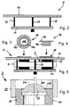
- Fig. 1 shows the first metal plate 10 and the second metal plate 11 of a first embodiment of a carrier according to the disclosure.
- the first metal plate 10 has twelve holes 100 therein, however, a different number of holes 100 is of course possible.
- the second metal plate 11 does not have any holes at all, since the molds are to be placed on second metal plate 11.
- Fig. 2 shows the first embodiment of carrier 1 in an assembled state, however, without any molds being placed on second metal plate 11.
- First and second metal plates 10,11 are connected to one another in an electrically conductive manner.
- Pins 12 are arranged at the four corners, as this is shown in Fig. 2 (and as is already indicated in Fig. 1 ).
- the two plates are fixed to one another with the aid of screws 13, as this is shown in Fig. 2 (and as is already indicated in Fig. 1 ).
- Fig. 3 and Fig. 4 show diaphragm inserts 14 which can be introduced into the holes after the molds have been arranged between the first and second plates 10,11 and after the first and second plates 10,11 have been fixed to one another with the aid of screws 13.
- the diaphragm inserts 14 comprise a cylindrical portion 140 and a laterally extending collar 141, and are provided with a diaphragm opening 142 having a diameter which is adapted to the diameter (size) of the molding surface of the respective mold.
- Mold 2 comprises a mount 20 to which a molding member 21 is mounted having a molding surface 210.
- the molding member is made of glass, for example quartz glass or BK7.
- a mask 212 has been applied, for example a chromium mask.
- Mold 2 further comprises a sleeve 22 that helps in centering the molds as male mold 2 and a corresponding female mold are closed to form a contact lens.
- Sleeve 22 is typically made from plastics so as to allow a smooth closing of male mold 2 and the corresponding female mold.
- first metal plate 10 with first metal plate being arranged on a plane surface, for example
- Second metal plate 11 is then fixed to first metal plate 10 with the aid of pins 12 which help in correctly arranging the first and second metal plates 10,11 with respect to one another, and with the aid of the screws 13 holding the first and second metal plates together with molds 2 arranged therebetween.
- a separate holder 3 may be provided holding a number of molds 2 at a distance from one another which corresponds to the distance between adjacent holes 100 in the first metal plate 10.
- such separate holders 3 are typically made from plastics so that they should also be shielded from being exposed to plasma to prevent the adverse effects discussed further above.
- first and second metal plates 10,11 have been fixed to one another with the molds 2 arranged therebetween, the arrangement of the first and second metal plates 10,11 is turned upside down so that first metal plate 10 is now arranged at the upper side and second metal plate is arranged at the lower side.
- the diaphragm inserts 14, which are made of metal, are now inserted into the sleeves 22 until collar 141 abuts against the upper surface of first metal plate 10.
- Carrier 1 is shown in Fig. 5 in its fully assembled state, with the molds 2 and separate holders 3 arranged between first and second metal plates 10,11 and with diaphragm inserts 14 inserted as described above.
- Fig. 7 shows the first metal plate 40 and second metal plate 41 of a second embodiment of the carrier according to the disclosure in an unassembled state
- Fig. 8 shows the first and second plates 40,41 of carrier 4 in an assembled state but without molds being arranged between the first and second metal plates 40,41.
- the first and second plates are provided with holes 400 and are both fixed to one another and connected to one another in an electrically conductive manner with the aid of screws 43.
- a difference of this embodiment of the carrier 4 when compared to the first embodiment of the carrier 1 is, that no diaphragm inserts are provided.
- carrier 4 with the separate holder 3 for the molds is shown.
- the way how to assemble the second embodiment of the carrier 4 with the molds and the holder 3 between the first and second plates 40 and 41, respectively, is similar to that already described for the first embodiment of the carrier 1.
- the second embodiment of the carrier 4 is particularly suitable for female molds, and since the female molds in the described embodiment do not have a sleeve (since this is already provided at the male molds) but are simply accomodated in metal pieces, no diaphragm inserts are needed for shielding any plastic component (such as the sleeve 22 in the first embodiment of the carrier 1) from exposure to plasma.
- Fig. 10 there is shown in a very schematic representation an embodiment of the apparatus 5 according to the invention.
- the apparatus comprises a treatment chamber 50, which is cylindrically shaped.
- Apparatus 5 of this embodiment further comprises a first electrode 51 and a second electrode 52, which are capable of generating a plasma between first electrode 51 and second electrode 52.
- a suitable plasma gas may be oxygen, for example.
- the second electrode 52 is formed by a carrier as it has been described above, for example by carrier 1 (or by carrier 4, respectively).
- the second electrode 52 is in electrically conductive contact with the wall 500 or walls of treatment chamber 50. That is to say, at least one of the first and second metal plates of carrier 1 (or carrier 4, respectively), is in contact with the wall 500 or wall of treatment chamber 50.
- the wall 500 which is also made from metal, e.g. from aluminum, may have ground potential.
- Second metal plate 11 Since the first and second metal plates 10,11 of carrier 1 are connected to one another in an electrically conductive manner, it is not possible for plasma ignition to occur between the first and second metal plates 10,11. However, it may nevertheless be possible for plasma to leak into the space below the second metal plate 11 due to suction which is continuosly applied to treatment chamber 50. Second metal plate 11, therefore, has not only the function of a support for the molds but in addition it forms a barrier for plasma that has leaked into the space below second metal plate 11.
- a metal plug may be inserted in that hole to shield any components arranged between first and second metal plates 10,11 from being exposed to plasma and/or to prevent or at least greatly reduce plasma leaking into the space between the first and second metal plates 10,11 or 40,41, respectively.
- all electrically conductive components such as metal plates, diaphragm inserts, plugs, pins, etc. be made from the same material, e.g. from metal such as aluminum.
Landscapes
- Physics & Mathematics (AREA)
- Engineering & Computer Science (AREA)
- Plasma & Fusion (AREA)
- Chemical & Material Sciences (AREA)
- Analytical Chemistry (AREA)
- Plasma Technology (AREA)
- Moulds For Moulding Plastics Or The Like (AREA)
Description
- The present invention relates to an apparatus for the plasma treatment of contact lens molds made of glass.
-
EP-A1-0 677 373 discloses an apparatus for the local O2 plasma treatment of the flange of a polystyrene contact lens mold, whereby flash adheres to said mold instead of adhering to the lens. - During production of contact lenses, in particular but not only during manufacturing of single wear contact lenses in very large batch numbers, reusable molds can be used which typically comprise two molds halves essentially made of glass, e.g. of quartz glass or of glass called BK7 available from the company Glaswerke Schott, Mainz, Germany. It has shown to be advantageous when the glass molds or mold halves, respectively, have been exposed to a plasma, e.g. an oxygen plasma, prior to using the molds in production. This is described in more detail, for example, in
EP-A-1 332 856 . - The glass molds or molds halves, respectively, may be arranged in a plastic sleeve which helps in properly centering the mold halves during closing of the mold, as this is described, for example, in
WO-A-99/20455 - Accordingly, it is an object of the invention to suggest an apparatus which prevents possible contamination of the molding surfaces of the glass molds during their exposure to plasma on one hand and on the other hand eliminate or at least greatly reduce exposure of any plastic components to plasma.
- This object is achieved by an apparatus for the plasma treatment of contact lens molds made of glass as characterized by the features of the independent claim.
- Advantageous embodiments of the apparatus are the subject of the respective dependent claims.
- In the following, when the term "mold" or "molds" is used it is intended to include the term "mold half" or "mold halves" wherever this is appropriate.
- In particular, the apparatus for the plasma treatment of contact lens molds made of glass, in accordance with the invention, is defined in
claim 1. - Due to the fact that the first and second metal plates are connected to one another in an electrically conductive manner, there is no difference in the electric potential (that is to say there is zero voltage) between the first and second plates forming the second electrode, so that no plasma ignition may occur between the first and second plates of the carrier. However, plasma ignition is to occur between the first and second electrode (the second electrode being formed by the carrier). Due to the arrangement of the molds on the second metal plate with their molding surfaces facing towards the first electrode through the holes of the first metal plate, the molding surfaces of the molds can be exposed to plasma, whereas the plastic sleeve in which the mold may be arranged, extends underneath the first metal plate, so that it is shielded from exposure to plasma. This prevents the molding surfaces of the molds from contamination through plastic, but more importantly it prevents or at least greatly reduces exposure of the plastic sleeve to plasma, thus avoiding the adverse effects on the plastic sleeves caused by their exposure to plasma.
- According to the invention, the apparatus comprises separate diaphragm inserts for the holes provided in the first metal plate. The diaphragm inserts each have an opening which is adapted to only expose the molding surface of the respective mold to plasma but to shield all other portions of the mold, in particular the inner faces of the plastic sleeves, from exposure. This embodiment is particularly advantageous since in this embodiment the openings in the first metal plate need not necessarily correspond to the size of the molding surfaces but can be larger than these. Depending on the respective size of the molding surface of a mold, it is possible to insert into the opening of the first metal plate a diaphragm having an opening having a size which is specifically adapted to the size of the molding surface of the respective mold. It is thus only necessary in case of molds having different sizes of molding surfaces to use the respective diaphragm insert, whereas the holes in the first metal plate of the carrier can be larger and, for example, these holes can all have the same size regardless of the size of the molding surfaces of the respective molds.
- In one embodiment of the apparatus according to the invention, the first and second metal plates of the carrier are dimensioned such that when the carrier is arranged within the treatment chamber at least one of the first and second metal plates is in contact with the wall or walls of the treatment chamber. This embodiment allows to apply the desired electric potential to the metal plates of the carrier by applying this electric potential to the wall or walls of the treatment chamber which is then transferred to the metal plates through the contact between the wall or walls of the treatment chamber and the metal plates of the carrier. Due to the fact that there is no difference in the electric potential (zero voltage) between the first and second metal plates, no plasma ignition may occur between the first and second plates. In a particular embodiment, the wall or walls of the treatment chamber are also made from metal and have ground potential.
- In a further embodiment of the apparatus according to the invention, two or more molds are arranged in a separate holder at a distance from one another which corresponds to the distance of the holes in the first metal plate, so that upon placement of the holder holding the two or more molds onto the second metal plate the holder is arranged between the first and second metal plates and the molds are arranged congruent to the holes in the first metal plate. This embodiment of the apparatus is particularly advantageous when separate holders for the molds are used during production of the contact lenses, since the molds or their molding surfaces, respectively, can then be exposed to plasma treatment with the molds already arranged in the respective holders which may be made from plastics and are shielded from exposure to plasma as already discussed above.
- The first and second metal plates can be made from aluminum or any other suitable electrically conductive material. In case there is no mold arranged in some of the holes of the first metal plate, in accordance with a further embodiment of the apparatus according to the invention metal plugs may be arranged in these holes so as to shield any plastic parts arranged between the two metal plates from being exposed to plasma. The plasma may be an oxygen plasma, for example.
- Further advantageous aspects of the invention will become apparent from the following detailed description of preferred embodiments, including embodiments of the invention, with the aid of the drawings in which:
- Fig. 1
- shows the first and second metal plates of a first embodiment of the carrier according to the disclosure,
- Fig. 2
- shows the first embodiment of the carrier according to the disclosure in an assembled state but without molds,
- Fig. 3
- shows a bottom view of an embodiment of a diaphragm insert which is to be inserted into a hole of the first metal plate,
- Fig. 4
- shows the diaphragm of
Fig. 3 in a side view, - Fig. 5
- shows an embodiment of a male mold that can be plasma treated using the first embodiment of the carrier according to the disclosure,
- Fig. 6
- shows the first embodiment of the carrier according to the disclosure in an assembled state with molds being arranged between the first and second metal plates and with diaphragms inserted,
- Fig. 7
- shows the first and second metal plates of a second embodiment of the carrier according to the disclosure,
- Fig. 8
- shows the second embodiment of the carrier according to the disclosure in an assembled state but without molds,
- Fig. 9
- shows the second embodiment of the carrier according to
Fig. 8 but with molds being arranged between the first and second metal plates, and - Fig. 10
- shows (schematically) an embodiment of the apparatus according to the invention.
-
Fig. 1 shows thefirst metal plate 10 and thesecond metal plate 11 of a first embodiment of a carrier according to the disclosure. In this embodiment, thefirst metal plate 10 has twelveholes 100 therein, however, a different number ofholes 100 is of course possible. Thesecond metal plate 11 does not have any holes at all, since the molds are to be placed onsecond metal plate 11. -
Fig. 2 shows the first embodiment ofcarrier 1 in an assembled state, however, without any molds being placed onsecond metal plate 11. First andsecond metal plates Pins 12 are arranged at the four corners, as this is shown inFig. 2 (and as is already indicated inFig. 1 ). The two plates are fixed to one another with the aid ofscrews 13, as this is shown inFig. 2 (and as is already indicated inFig. 1 ). -
Fig. 3 and Fig. 4 show diaphragm inserts 14 which can be introduced into the holes after the molds have been arranged between the first andsecond plates second plates screws 13. Thediaphragm inserts 14 comprise acylindrical portion 140 and a laterally extendingcollar 141, and are provided with a diaphragm opening 142 having a diameter which is adapted to the diameter (size) of the molding surface of the respective mold. - By way of example, let us assume that the molds are male molds and look essentially like
mold 2 represented inFig. 6 .Mold 2 comprises amount 20 to which amolding member 21 is mounted having amolding surface 210. The molding member is made of glass, for example quartz glass or BK7. At aperipheral portion 211 of molding member 21 amask 212 has been applied, for example a chromium mask.Mold 2 further comprises asleeve 22 that helps in centering the molds asmale mold 2 and a corresponding female mold are closed to form a contact lens.Sleeve 22 is typically made from plastics so as to allow a smooth closing ofmale mold 2 and the corresponding female mold. - In order to assemble the carrier 1 (assembled carrier shown in
Fig. 5 ), firstly themolds 2 are introduced into theholes 100 of first metal plate 10 (with first metal plate being arranged on a plane surface, for example) with the distal ends ofsleeves 22 protruding intoholes 100.Second metal plate 11 is then fixed tofirst metal plate 10 with the aid ofpins 12 which help in correctly arranging the first andsecond metal plates screws 13 holding the first and second metal plates together withmolds 2 arranged therebetween. Aseparate holder 3 may be provided holding a number ofmolds 2 at a distance from one another which corresponds to the distance betweenadjacent holes 100 in thefirst metal plate 10. However, suchseparate holders 3 are typically made from plastics so that they should also be shielded from being exposed to plasma to prevent the adverse effects discussed further above. - As the first and
second metal plates molds 2 arranged therebetween, the arrangement of the first andsecond metal plates first metal plate 10 is now arranged at the upper side and second metal plate is arranged at the lower side. The diaphragm inserts 14, which are made of metal, are now inserted into thesleeves 22 untilcollar 141 abuts against the upper surface offirst metal plate 10. Thecylindrical portion 140 then shields the inner wall ofsleeve 20 from being exposed to plasma while opening 142 allows only those portions of themolds 2 which are made of glass (or metal portions of the molds 2) to be exposed to plasma, that is to say only the molding surfaces 210 of themolds 2, while all other portions of the molds are shielded from exposure to plasma.Carrier 1 is shown inFig. 5 in its fully assembled state, with themolds 2 andseparate holders 3 arranged between first andsecond metal plates -
Fig. 7 shows thefirst metal plate 40 andsecond metal plate 41 of a second embodiment of the carrier according to the disclosure in an unassembled state, whereasFig. 8 shows the first andsecond plates carrier 4 in an assembled state but without molds being arranged between the first andsecond metal plates holes 400 and are both fixed to one another and connected to one another in an electrically conductive manner with the aid ofscrews 43. In this embodiment there are no additional pins arranged at the corners of the first andsecond plates carrier 4 when compared to the first embodiment of thecarrier 1 is, that no diaphragm inserts are provided. InFig. 9 carrier 4 with theseparate holder 3 for the molds is shown. - The way how to assemble the second embodiment of the
carrier 4 with the molds and theholder 3 between the first andsecond plates carrier 1. However, since the second embodiment of thecarrier 4 is particularly suitable for female molds, and since the female molds in the described embodiment do not have a sleeve (since this is already provided at the male molds) but are simply accomodated in metal pieces, no diaphragm inserts are needed for shielding any plastic component (such as thesleeve 22 in the first embodiment of the carrier 1) from exposure to plasma. - In
Fig. 10 there is shown in a very schematic representation an embodiment of theapparatus 5 according to the invention. The apparatus comprises atreatment chamber 50, which is cylindrically shaped.Apparatus 5 of this embodiment further comprises afirst electrode 51 and asecond electrode 52, which are capable of generating a plasma betweenfirst electrode 51 andsecond electrode 52. A suitable plasma gas may be oxygen, for example. Thesecond electrode 52 is formed by a carrier as it has been described above, for example by carrier 1 (or bycarrier 4, respectively). As is schematically shown inFig. 10 , thesecond electrode 52 is in electrically conductive contact with the wall 500 or walls oftreatment chamber 50. That is to say, at least one of the first and second metal plates of carrier 1 (orcarrier 4, respectively), is in contact with the wall 500 or wall oftreatment chamber 50. The wall 500, which is also made from metal, e.g. from aluminum, may have ground potential. - Since the first and
second metal plates carrier 1 are connected to one another in an electrically conductive manner, it is not possible for plasma ignition to occur between the first andsecond metal plates second metal plate 11 due to suction which is continuosly applied totreatment chamber 50.Second metal plate 11, therefore, has not only the function of a support for the molds but in addition it forms a barrier for plasma that has leaked into the space belowsecond metal plate 11. - Also, in case no mold is present in one or more of the holes of the
first metal plate second metal plates second metal plates - It is preferred although not mandatory, that all electrically conductive components such as metal plates, diaphragm inserts, plugs, pins, etc. be made from the same material, e.g. from metal such as aluminum.
Claims (7)
- Apparatus for the plasma treatment of contact lens molds made of glass, comprising a treatment chamber (50), in which a first electrode (51) is arranged facing a carrier (1;4), which is arranged to carry the contact lens molds (2) to be treated and to form the second electrode (52), characterized in that the carrier (1; 4) comprises a first metal plate (10;40) having holes (100;400) therein and a second metal plate (11;41) which is arranged spaced apart from the first metal plate (10;40), which is connected to the first metal plate (10;40) in an electrically conductive manner (12,13;43), and which is arranged to support the contact lens molds (2) with their molding surfaces (210) facing towards the first electrode (51) and being exposable to plasma through the holes (100;400) in the first metal plate (10;40), the apparatus further comprising separate diaphragm inserts (14) for the holes provided in the first metal plate (10), with the diaphragm inserts (14) each having an opening (142) which is adapted to only expose the molding surface (210) of the respective contact lens mold (2) but to shield all other portions of the contact lens mold (2) from exposure to plasma.
- Apparatus according to claim 1, wherein the first and second metal plates (10,11;40,41) of the carrier are dimensioned such that when the carrier (1;4) is arranged within the treatment chamber (50) at least one of the first and second metal plates (10,11;40,41) is in contact with the wall (500) or walls of the treatment chamber (50).
- Apparatus according to any one of the preceding claims, wherein the wall (500) or walls of the treatment chamber (50) is/are made of metal and has/have ground potential.
- Apparatus according to any one of the preceding claims, wherein two or more contact lens molds (2) are arranged in a separate holder (3) at a distance from one another which corresponds to the distance of the holes (100;400) in the first metal plate (10;40), so that upon placement of the holder (3) holding the two or more contact lens molds (2) onto the second metal plate (11;41) the holder (3) is arranged between the first and second metal plates and the contact lens molds (2) are arranged congruent to the holes (100;400) in the first metal plate (10;40).
- Apparatus according to any one of the preceding claims, wherein the first and second metal plates (10,11;40,41) are made from aluminum.
- Apparatus according to any one of the preceding claims, wherein metal plugs are arranged in holes of the first metal plate (10;40) where no mold is arranged in the hole (100;400).
- Apparatus according to any one of the preceding claims, wherein the plasma is an oxygen plasma.
Priority Applications (1)
| Application Number | Priority Date | Filing Date | Title |
|---|---|---|---|
| EP09703759.2A EP2243148B1 (en) | 2008-01-25 | 2009-01-21 | Apparatus for the plasma treatment of contact lens molds made of glass |
Applications Claiming Priority (3)
| Application Number | Priority Date | Filing Date | Title |
|---|---|---|---|
| EP08100923 | 2008-01-25 | ||
| PCT/EP2009/050651 WO2009092729A2 (en) | 2008-01-25 | 2009-01-21 | Apparatus, carrier and method for the plasma treatment of molds |
| EP09703759.2A EP2243148B1 (en) | 2008-01-25 | 2009-01-21 | Apparatus for the plasma treatment of contact lens molds made of glass |
Publications (2)
| Publication Number | Publication Date |
|---|---|
| EP2243148A2 EP2243148A2 (en) | 2010-10-27 |
| EP2243148B1 true EP2243148B1 (en) | 2016-08-03 |
Family
ID=39333179
Family Applications (1)
| Application Number | Title | Priority Date | Filing Date |
|---|---|---|---|
| EP09703759.2A Active EP2243148B1 (en) | 2008-01-25 | 2009-01-21 | Apparatus for the plasma treatment of contact lens molds made of glass |
Country Status (6)
| Country | Link |
|---|---|
| US (1) | US8333868B2 (en) |
| EP (1) | EP2243148B1 (en) |
| CN (1) | CN101925975B (en) |
| HU (1) | HUE029850T2 (en) |
| MY (1) | MY151567A (en) |
| WO (1) | WO2009092729A2 (en) |
Families Citing this family (1)
| Publication number | Priority date | Publication date | Assignee | Title |
|---|---|---|---|---|
| CN102512702B (en) * | 2011-12-30 | 2013-09-11 | 杭州视亨光电有限公司 | Low-temperature plasma instrument for caring corneal contact lens |
Citations (2)
| Publication number | Priority date | Publication date | Assignee | Title |
|---|---|---|---|---|
| US4534921A (en) * | 1984-03-06 | 1985-08-13 | Asm Fico Tooling, B.V. | Method and apparatus for mold cleaning by reverse sputtering |
| JPH01141923A (en) * | 1987-11-30 | 1989-06-02 | Hitachi Ltd | plasma processing equipment |
Family Cites Families (19)
| Publication number | Priority date | Publication date | Assignee | Title |
|---|---|---|---|---|
| JP2572438B2 (en) * | 1989-01-30 | 1997-01-16 | ホーヤ株式会社 | Manufacturing method of glass press mold |
| US5573715A (en) * | 1992-12-21 | 1996-11-12 | Johnson & Johnson Vision Products, Inc. | Method for treating an ophthalmic lens mold |
| US5769953A (en) * | 1995-05-01 | 1998-06-23 | Bridgestone Corporation | Plasma and heating method of cleaning vulcanizing mold for ashing residue |
| ES2164947T3 (en) * | 1996-02-15 | 2002-03-01 | Bridgestone Corp | METHOD FOR CLEANING A VULCANIZATION MOLD. |
| JP3623590B2 (en) * | 1996-04-04 | 2005-02-23 | 株式会社ブリヂストン | Vulcanizing mold cleaning equipment |
| TW347363B (en) * | 1996-11-12 | 1998-12-11 | Bae-Hyeock Chun | Method for improving demolding effect of a mold by a low temperature plasma process |
| SE512400C2 (en) * | 1997-07-31 | 2000-03-13 | Ericsson Telefon Ab L M | Coaxial connector |
| DE19740097B4 (en) | 1997-09-15 | 2012-03-29 | Kaco Gmbh + Co | Process for the surface treatment of parts of hard-to-activate plastics and equipment for carrying out such a process |
| TW429327B (en) * | 1997-10-21 | 2001-04-11 | Novartis Ag | Single mould alignment |
| US20020032073A1 (en) * | 1998-02-11 | 2002-03-14 | Joseph J. Rogers | Highly durable and abrasion resistant composite diamond-like carbon decorative coatings with controllable color for metal substrates |
| AR021819A1 (en) * | 1998-09-30 | 2002-08-07 | Novartis Ag | APPARATUS AND METHOD FOR CLEANING OPHTHALM COMPONENTS |
| US6497000B1 (en) * | 1999-09-30 | 2002-12-24 | Novartis Ag | Apparatus for cleaning ophthalmic components |
| GB2360730B (en) * | 2000-03-31 | 2004-09-22 | Bausch & Lomb Uk Ltd | Apparatus and method for separating contact lens molds |
| DE10109565B4 (en) * | 2001-02-28 | 2005-10-20 | Vacuheat Gmbh | Method and device for partial thermochemical vacuum treatment of metallic workpieces |
| EP1332856B1 (en) * | 2002-01-31 | 2008-02-27 | Novartis AG | Process for treating moulds or mould halves for the production of ophthalmic lenses |
| US7059335B2 (en) * | 2002-01-31 | 2006-06-13 | Novartis Ag | Process for treating moulds or mould halves for the production of ophthalmic lenses |
| US20040211217A1 (en) * | 2002-09-11 | 2004-10-28 | Hoya Corporation | Method of regenerating pressing molds and method of manufacturing optical elements |
| WO2004107394A2 (en) * | 2003-05-27 | 2004-12-09 | Matsushita Electric Works, Ltd. | Plasma processing apparatus, method for producing reaction vessel for plasma generation, and plasma processing method |
| TWI245701B (en) * | 2004-02-06 | 2005-12-21 | Asia Optical Co Inc | Die set with multiple removable mold cores |
-
2009
- 2009-01-21 CN CN2009801029057A patent/CN101925975B/en active Active
- 2009-01-21 MY MYPI20102548 patent/MY151567A/en unknown
- 2009-01-21 US US12/321,444 patent/US8333868B2/en active Active
- 2009-01-21 WO PCT/EP2009/050651 patent/WO2009092729A2/en not_active Ceased
- 2009-01-21 EP EP09703759.2A patent/EP2243148B1/en active Active
- 2009-01-21 HU HUE09703759A patent/HUE029850T2/en unknown
Patent Citations (2)
| Publication number | Priority date | Publication date | Assignee | Title |
|---|---|---|---|---|
| US4534921A (en) * | 1984-03-06 | 1985-08-13 | Asm Fico Tooling, B.V. | Method and apparatus for mold cleaning by reverse sputtering |
| JPH01141923A (en) * | 1987-11-30 | 1989-06-02 | Hitachi Ltd | plasma processing equipment |
Also Published As
| Publication number | Publication date |
|---|---|
| EP2243148A2 (en) | 2010-10-27 |
| US8333868B2 (en) | 2012-12-18 |
| WO2009092729A2 (en) | 2009-07-30 |
| HUE029850T2 (en) | 2017-04-28 |
| CN101925975B (en) | 2013-07-17 |
| US20090188525A1 (en) | 2009-07-30 |
| WO2009092729A3 (en) | 2009-10-29 |
| MY151567A (en) | 2014-06-13 |
| CN101925975A (en) | 2010-12-22 |
Similar Documents
| Publication | Publication Date | Title |
|---|---|---|
| US11965262B2 (en) | Substrate supporting plate, thin film deposition apparatus including the same, and thin film deposition method | |
| US5371355A (en) | Night vision device with separable modular image intensifier assembly | |
| MY162316A (en) | Demolding and delensing methods and systems in the manufacture of silicone hydrogel contact lenses | |
| ES2089562T3 (en) | METHOD AND APPARATUS FOR MOLDING LENSES. | |
| EP2243148B1 (en) | Apparatus for the plasma treatment of contact lens molds made of glass | |
| JP2012502816A (en) | Molded parts for optical purposes, especially filter rings or lens holders | |
| KR950704101A (en) | Method for removing excess lens forming material | |
| US6813005B2 (en) | Storage containers for lithography mask and method of use | |
| KR20160047857A (en) | Wafer Tray and Assemblying Jig and Methof for the Wafer Tray | |
| TW202331412A (en) | Gas distribution plate with uv blocker at the center | |
| US6130497A (en) | Liquid cooling type cathode-ray tube for a projector | |
| WO2002009143A3 (en) | Ruggedized photomultiplier tube and optical coupling in armored detector | |
| KR101120793B1 (en) | Photomask mounting/housing device and resist inspection method and resist inspection apparatus using same | |
| JPH01154414A (en) | Manufacture of light radiation type contact rubber | |
| TWI401465B (en) | Apparatus and method for coating lens | |
| CN104723484B (en) | 360-degree ultrasonic endoscope molding device | |
| US3871610A (en) | Optical mold forming means | |
| RU2412817C2 (en) | Device and method of alignment of robot tool and casting machine | |
| KR101616791B1 (en) | A sputtering cover | |
| JP6990254B2 (en) | Dental implant packaging container | |
| WO2025009971A1 (en) | Method of manufacturing a mould for an optical element | |
| KR100810043B1 (en) | Fine pattern defect correction method | |
| JPH10177105A (en) | Composite optical element | |
| KR101616792B1 (en) | The method for manufacturing a sputtering cover | |
| CN103217864A (en) | Exposure method of electroformed mask plate |
Legal Events
| Date | Code | Title | Description |
|---|---|---|---|
| PUAI | Public reference made under article 153(3) epc to a published international application that has entered the european phase |
Free format text: ORIGINAL CODE: 0009012 |
|
| 17P | Request for examination filed |
Effective date: 20100823 |
|
| AK | Designated contracting states |
Kind code of ref document: A2 Designated state(s): AT BE BG CH CY CZ DE DK EE ES FI FR GB GR HR HU IE IS IT LI LT LU LV MC MK MT NL NO PL PT RO SE SI SK TR |
|
| AX | Request for extension of the european patent |
Extension state: AL BA RS |
|
| DAX | Request for extension of the european patent (deleted) | ||
| 17Q | First examination report despatched |
Effective date: 20150616 |
|
| GRAP | Despatch of communication of intention to grant a patent |
Free format text: ORIGINAL CODE: EPIDOSNIGR1 |
|
| RIC1 | Information provided on ipc code assigned before grant |
Ipc: C23C 16/04 20060101ALI20160210BHEP Ipc: H01J 37/32 20060101AFI20160210BHEP |
|
| INTG | Intention to grant announced |
Effective date: 20160226 |
|
| GRAS | Grant fee paid |
Free format text: ORIGINAL CODE: EPIDOSNIGR3 |
|
| GRAA | (expected) grant |
Free format text: ORIGINAL CODE: 0009210 |
|
| AK | Designated contracting states |
Kind code of ref document: B1 Designated state(s): AT BE BG CH CY CZ DE DK EE ES FI FR GB GR HR HU IE IS IT LI LT LU LV MC MK MT NL NO PL PT RO SE SI SK TR |
|
| REG | Reference to a national code |
Ref country code: GB Ref legal event code: FG4D |
|
| REG | Reference to a national code |
Ref country code: CH Ref legal event code: EP Ref country code: AT Ref legal event code: REF Ref document number: 817840 Country of ref document: AT Kind code of ref document: T Effective date: 20160815 |
|
| REG | Reference to a national code |
Ref country code: IE Ref legal event code: FG4D |
|
| REG | Reference to a national code |
Ref country code: DE Ref legal event code: R096 Ref document number: 602009040089 Country of ref document: DE |
|
| REG | Reference to a national code |
Ref country code: NL Ref legal event code: MP Effective date: 20160803 |
|
| REG | Reference to a national code |
Ref country code: LT Ref legal event code: MG4D |
|
| REG | Reference to a national code |
Ref country code: AT Ref legal event code: MK05 Ref document number: 817840 Country of ref document: AT Kind code of ref document: T Effective date: 20160803 |
|
| PG25 | Lapsed in a contracting state [announced via postgrant information from national office to epo] |
Ref country code: NL Free format text: LAPSE BECAUSE OF FAILURE TO SUBMIT A TRANSLATION OF THE DESCRIPTION OR TO PAY THE FEE WITHIN THE PRESCRIBED TIME-LIMIT Effective date: 20160803 Ref country code: IT Free format text: LAPSE BECAUSE OF FAILURE TO SUBMIT A TRANSLATION OF THE DESCRIPTION OR TO PAY THE FEE WITHIN THE PRESCRIBED TIME-LIMIT Effective date: 20160803 Ref country code: IS Free format text: LAPSE BECAUSE OF FAILURE TO SUBMIT A TRANSLATION OF THE DESCRIPTION OR TO PAY THE FEE WITHIN THE PRESCRIBED TIME-LIMIT Effective date: 20161203 Ref country code: NO Free format text: LAPSE BECAUSE OF FAILURE TO SUBMIT A TRANSLATION OF THE DESCRIPTION OR TO PAY THE FEE WITHIN THE PRESCRIBED TIME-LIMIT Effective date: 20161103 Ref country code: LT Free format text: LAPSE BECAUSE OF FAILURE TO SUBMIT A TRANSLATION OF THE DESCRIPTION OR TO PAY THE FEE WITHIN THE PRESCRIBED TIME-LIMIT Effective date: 20160803 Ref country code: FI Free format text: LAPSE BECAUSE OF FAILURE TO SUBMIT A TRANSLATION OF THE DESCRIPTION OR TO PAY THE FEE WITHIN THE PRESCRIBED TIME-LIMIT Effective date: 20160803 Ref country code: HR Free format text: LAPSE BECAUSE OF FAILURE TO SUBMIT A TRANSLATION OF THE DESCRIPTION OR TO PAY THE FEE WITHIN THE PRESCRIBED TIME-LIMIT Effective date: 20160803 |
|
| PG25 | Lapsed in a contracting state [announced via postgrant information from national office to epo] |
Ref country code: PT Free format text: LAPSE BECAUSE OF FAILURE TO SUBMIT A TRANSLATION OF THE DESCRIPTION OR TO PAY THE FEE WITHIN THE PRESCRIBED TIME-LIMIT Effective date: 20161205 Ref country code: AT Free format text: LAPSE BECAUSE OF FAILURE TO SUBMIT A TRANSLATION OF THE DESCRIPTION OR TO PAY THE FEE WITHIN THE PRESCRIBED TIME-LIMIT Effective date: 20160803 Ref country code: SE Free format text: LAPSE BECAUSE OF FAILURE TO SUBMIT A TRANSLATION OF THE DESCRIPTION OR TO PAY THE FEE WITHIN THE PRESCRIBED TIME-LIMIT Effective date: 20160803 Ref country code: ES Free format text: LAPSE BECAUSE OF FAILURE TO SUBMIT A TRANSLATION OF THE DESCRIPTION OR TO PAY THE FEE WITHIN THE PRESCRIBED TIME-LIMIT Effective date: 20160803 Ref country code: PL Free format text: LAPSE BECAUSE OF FAILURE TO SUBMIT A TRANSLATION OF THE DESCRIPTION OR TO PAY THE FEE WITHIN THE PRESCRIBED TIME-LIMIT Effective date: 20160803 Ref country code: GR Free format text: LAPSE BECAUSE OF FAILURE TO SUBMIT A TRANSLATION OF THE DESCRIPTION OR TO PAY THE FEE WITHIN THE PRESCRIBED TIME-LIMIT Effective date: 20161104 Ref country code: LV Free format text: LAPSE BECAUSE OF FAILURE TO SUBMIT A TRANSLATION OF THE DESCRIPTION OR TO PAY THE FEE WITHIN THE PRESCRIBED TIME-LIMIT Effective date: 20160803 |
|
| PG25 | Lapsed in a contracting state [announced via postgrant information from national office to epo] |
Ref country code: RO Free format text: LAPSE BECAUSE OF FAILURE TO SUBMIT A TRANSLATION OF THE DESCRIPTION OR TO PAY THE FEE WITHIN THE PRESCRIBED TIME-LIMIT Effective date: 20160803 Ref country code: EE Free format text: LAPSE BECAUSE OF FAILURE TO SUBMIT A TRANSLATION OF THE DESCRIPTION OR TO PAY THE FEE WITHIN THE PRESCRIBED TIME-LIMIT Effective date: 20160803 |
|
| REG | Reference to a national code |
Ref country code: HU Ref legal event code: AG4A Ref document number: E029850 Country of ref document: HU |
|
| REG | Reference to a national code |
Ref country code: DE Ref legal event code: R097 Ref document number: 602009040089 Country of ref document: DE |
|
| PG25 | Lapsed in a contracting state [announced via postgrant information from national office to epo] |
Ref country code: BE Free format text: LAPSE BECAUSE OF FAILURE TO SUBMIT A TRANSLATION OF THE DESCRIPTION OR TO PAY THE FEE WITHIN THE PRESCRIBED TIME-LIMIT Effective date: 20160803 Ref country code: BG Free format text: LAPSE BECAUSE OF FAILURE TO SUBMIT A TRANSLATION OF THE DESCRIPTION OR TO PAY THE FEE WITHIN THE PRESCRIBED TIME-LIMIT Effective date: 20161103 Ref country code: SK Free format text: LAPSE BECAUSE OF FAILURE TO SUBMIT A TRANSLATION OF THE DESCRIPTION OR TO PAY THE FEE WITHIN THE PRESCRIBED TIME-LIMIT Effective date: 20160803 Ref country code: DK Free format text: LAPSE BECAUSE OF FAILURE TO SUBMIT A TRANSLATION OF THE DESCRIPTION OR TO PAY THE FEE WITHIN THE PRESCRIBED TIME-LIMIT Effective date: 20160803 Ref country code: CZ Free format text: LAPSE BECAUSE OF FAILURE TO SUBMIT A TRANSLATION OF THE DESCRIPTION OR TO PAY THE FEE WITHIN THE PRESCRIBED TIME-LIMIT Effective date: 20160803 |
|
| PLBE | No opposition filed within time limit |
Free format text: ORIGINAL CODE: 0009261 |
|
| STAA | Information on the status of an ep patent application or granted ep patent |
Free format text: STATUS: NO OPPOSITION FILED WITHIN TIME LIMIT |
|
| 26N | No opposition filed |
Effective date: 20170504 |
|
| PG25 | Lapsed in a contracting state [announced via postgrant information from national office to epo] |
Ref country code: SI Free format text: LAPSE BECAUSE OF FAILURE TO SUBMIT A TRANSLATION OF THE DESCRIPTION OR TO PAY THE FEE WITHIN THE PRESCRIBED TIME-LIMIT Effective date: 20160803 |
|
| REG | Reference to a national code |
Ref country code: CH Ref legal event code: PL |
|
| PG25 | Lapsed in a contracting state [announced via postgrant information from national office to epo] |
Ref country code: MC Free format text: LAPSE BECAUSE OF FAILURE TO SUBMIT A TRANSLATION OF THE DESCRIPTION OR TO PAY THE FEE WITHIN THE PRESCRIBED TIME-LIMIT Effective date: 20160803 |
|
| REG | Reference to a national code |
Ref country code: FR Ref legal event code: ST Effective date: 20170929 |
|
| PG25 | Lapsed in a contracting state [announced via postgrant information from national office to epo] |
Ref country code: LI Free format text: LAPSE BECAUSE OF NON-PAYMENT OF DUE FEES Effective date: 20170131 Ref country code: FR Free format text: LAPSE BECAUSE OF NON-PAYMENT OF DUE FEES Effective date: 20170131 Ref country code: CH Free format text: LAPSE BECAUSE OF NON-PAYMENT OF DUE FEES Effective date: 20170131 |
|
| PG25 | Lapsed in a contracting state [announced via postgrant information from national office to epo] |
Ref country code: LU Free format text: LAPSE BECAUSE OF NON-PAYMENT OF DUE FEES Effective date: 20170121 |
|
| PG25 | Lapsed in a contracting state [announced via postgrant information from national office to epo] |
Ref country code: MT Free format text: LAPSE BECAUSE OF NON-PAYMENT OF DUE FEES Effective date: 20170121 |
|
| PG25 | Lapsed in a contracting state [announced via postgrant information from national office to epo] |
Ref country code: CY Free format text: LAPSE BECAUSE OF NON-PAYMENT OF DUE FEES Effective date: 20160803 |
|
| REG | Reference to a national code |
Ref country code: HU Ref legal event code: GB9C Owner name: ALCON INC., CH Free format text: FORMER OWNER(S): NOVARTIS AG, CH |
|
| PG25 | Lapsed in a contracting state [announced via postgrant information from national office to epo] |
Ref country code: MK Free format text: LAPSE BECAUSE OF FAILURE TO SUBMIT A TRANSLATION OF THE DESCRIPTION OR TO PAY THE FEE WITHIN THE PRESCRIBED TIME-LIMIT Effective date: 20160803 |
|
| REG | Reference to a national code |
Ref country code: DE Ref legal event code: R081 Ref document number: 602009040089 Country of ref document: DE Owner name: ALCON INC., CH Free format text: FORMER OWNER: NOVARTIS AG, 4056 BASEL, CH |
|
| REG | Reference to a national code |
Ref country code: GB Ref legal event code: 732E Free format text: REGISTERED BETWEEN 20200123 AND 20200129 |
|
| PG25 | Lapsed in a contracting state [announced via postgrant information from national office to epo] |
Ref country code: TR Free format text: LAPSE BECAUSE OF FAILURE TO SUBMIT A TRANSLATION OF THE DESCRIPTION OR TO PAY THE FEE WITHIN THE PRESCRIBED TIME-LIMIT Effective date: 20160803 |
|
| P01 | Opt-out of the competence of the unified patent court (upc) registered |
Effective date: 20230504 |
|
| PGFP | Annual fee paid to national office [announced via postgrant information from national office to epo] |
Ref country code: GB Payment date: 20241219 Year of fee payment: 17 |
|
| PGFP | Annual fee paid to national office [announced via postgrant information from national office to epo] |
Ref country code: IE Payment date: 20241224 Year of fee payment: 17 |
|
| PGFP | Annual fee paid to national office [announced via postgrant information from national office to epo] |
Ref country code: HU Payment date: 20250113 Year of fee payment: 17 |
|
| PGFP | Annual fee paid to national office [announced via postgrant information from national office to epo] |
Ref country code: DE Payment date: 20241217 Year of fee payment: 17 |