EP2243097B1 - Consumable assembly for use in extrusion-based layered deposition systems - Google Patents
Consumable assembly for use in extrusion-based layered deposition systems Download PDFInfo
- Publication number
- EP2243097B1 EP2243097B1 EP09701222.3A EP09701222A EP2243097B1 EP 2243097 B1 EP2243097 B1 EP 2243097B1 EP 09701222 A EP09701222 A EP 09701222A EP 2243097 B1 EP2243097 B1 EP 2243097B1
- Authority
- EP
- European Patent Office
- Prior art keywords
- filament
- extrusion
- consumable assembly
- assembly
- deposition system
- Prior art date
- Legal status (The legal status is an assumption and is not a legal conclusion. Google has not performed a legal analysis and makes no representation as to the accuracy of the status listed.)
- Active
Links
Images


Classifications
-
- B—PERFORMING OPERATIONS; TRANSPORTING
- B29—WORKING OF PLASTICS; WORKING OF SUBSTANCES IN A PLASTIC STATE IN GENERAL
- B29C—SHAPING OR JOINING OF PLASTICS; SHAPING OF MATERIAL IN A PLASTIC STATE, NOT OTHERWISE PROVIDED FOR; AFTER-TREATMENT OF THE SHAPED PRODUCTS, e.g. REPAIRING
- B29C64/00—Additive manufacturing, i.e. manufacturing of three-dimensional [3D] objects by additive deposition, additive agglomeration or additive layering, e.g. by 3D printing, stereolithography or selective laser sintering
- B29C64/10—Processes of additive manufacturing
- B29C64/106—Processes of additive manufacturing using only liquids or viscous materials, e.g. depositing a continuous bead of viscous material
- B29C64/118—Processes of additive manufacturing using only liquids or viscous materials, e.g. depositing a continuous bead of viscous material using filamentary material being melted, e.g. fused deposition modelling [FDM]
-
- B—PERFORMING OPERATIONS; TRANSPORTING
- B29—WORKING OF PLASTICS; WORKING OF SUBSTANCES IN A PLASTIC STATE IN GENERAL
- B29C—SHAPING OR JOINING OF PLASTICS; SHAPING OF MATERIAL IN A PLASTIC STATE, NOT OTHERWISE PROVIDED FOR; AFTER-TREATMENT OF THE SHAPED PRODUCTS, e.g. REPAIRING
- B29C48/00—Extrusion moulding, i.e. expressing the moulding material through a die or nozzle which imparts the desired form; Apparatus therefor
- B29C48/03—Extrusion moulding, i.e. expressing the moulding material through a die or nozzle which imparts the desired form; Apparatus therefor characterised by the shape of the extruded material at extrusion
- B29C48/05—Filamentary, e.g. strands
-
- B—PERFORMING OPERATIONS; TRANSPORTING
- B29—WORKING OF PLASTICS; WORKING OF SUBSTANCES IN A PLASTIC STATE IN GENERAL
- B29C—SHAPING OR JOINING OF PLASTICS; SHAPING OF MATERIAL IN A PLASTIC STATE, NOT OTHERWISE PROVIDED FOR; AFTER-TREATMENT OF THE SHAPED PRODUCTS, e.g. REPAIRING
- B29C48/00—Extrusion moulding, i.e. expressing the moulding material through a die or nozzle which imparts the desired form; Apparatus therefor
- B29C48/16—Articles comprising two or more components, e.g. co-extruded layers
- B29C48/18—Articles comprising two or more components, e.g. co-extruded layers the components being layers
-
- B—PERFORMING OPERATIONS; TRANSPORTING
- B29—WORKING OF PLASTICS; WORKING OF SUBSTANCES IN A PLASTIC STATE IN GENERAL
- B29C—SHAPING OR JOINING OF PLASTICS; SHAPING OF MATERIAL IN A PLASTIC STATE, NOT OTHERWISE PROVIDED FOR; AFTER-TREATMENT OF THE SHAPED PRODUCTS, e.g. REPAIRING
- B29C64/00—Additive manufacturing, i.e. manufacturing of three-dimensional [3D] objects by additive deposition, additive agglomeration or additive layering, e.g. by 3D printing, stereolithography or selective laser sintering
- B29C64/20—Apparatus for additive manufacturing; Details thereof or accessories therefor
- B29C64/205—Means for applying layers
- B29C64/209—Heads; Nozzles
-
- B—PERFORMING OPERATIONS; TRANSPORTING
- B29—WORKING OF PLASTICS; WORKING OF SUBSTANCES IN A PLASTIC STATE IN GENERAL
- B29C—SHAPING OR JOINING OF PLASTICS; SHAPING OF MATERIAL IN A PLASTIC STATE, NOT OTHERWISE PROVIDED FOR; AFTER-TREATMENT OF THE SHAPED PRODUCTS, e.g. REPAIRING
- B29C64/00—Additive manufacturing, i.e. manufacturing of three-dimensional [3D] objects by additive deposition, additive agglomeration or additive layering, e.g. by 3D printing, stereolithography or selective laser sintering
- B29C64/20—Apparatus for additive manufacturing; Details thereof or accessories therefor
- B29C64/255—Enclosures for the building material, e.g. powder containers
-
- B—PERFORMING OPERATIONS; TRANSPORTING
- B33—ADDITIVE MANUFACTURING TECHNOLOGY
- B33Y—ADDITIVE MANUFACTURING, i.e. MANUFACTURING OF THREE-DIMENSIONAL [3-D] OBJECTS BY ADDITIVE DEPOSITION, ADDITIVE AGGLOMERATION OR ADDITIVE LAYERING, e.g. BY 3-D PRINTING, STEREOLITHOGRAPHY OR SELECTIVE LASER SINTERING
- B33Y40/00—Auxiliary operations or equipment, e.g. for material handling
-
- B—PERFORMING OPERATIONS; TRANSPORTING
- B33—ADDITIVE MANUFACTURING TECHNOLOGY
- B33Y—ADDITIVE MANUFACTURING, i.e. MANUFACTURING OF THREE-DIMENSIONAL [3-D] OBJECTS BY ADDITIVE DEPOSITION, ADDITIVE AGGLOMERATION OR ADDITIVE LAYERING, e.g. BY 3-D PRINTING, STEREOLITHOGRAPHY OR SELECTIVE LASER SINTERING
- B33Y30/00—Apparatus for additive manufacturing; Details thereof or accessories therefor
Definitions
- the present invention relates to extrusion-based layered deposition systems for building three-dimensional (3D) objects with rapid prototyping/manufacturing techniques.
- the present invention relates to consumable materials for use in extrusion-based layered deposition systems.
- An extrusion-based layered deposition system e.g., fused deposition modeling systems developed by Stratasys, Inc., Eden Prairie, MN
- CAD computer-aided design
- the build material is extruded through an extrusion tip carried by an extrusion head, and is deposited as a sequence of roads on a substrate in an x-y plane.
- the extruded build material fuses to previously deposited build material, and solidifies upon a drop in temperature.
- the position of the extrusion head relative to the substrate is then incremented along a z-axis (perpendicular to the x-y plane), and the process is then repeated to form a 3D object resembling the CAD model.
- Movement of the extrusion head with respect to the substrate is performed under computer control, in accordance with build data that represents the 3D object.
- the build data is obtained by initially slicing the CAD model of the 3D object into multiple horizontally sliced layers. Then, for each sliced layer, the host computer generates a build path for depositing roads of build material to form the 3D object.
- the present invention relates to a consumable assembly for building 3D objects with an extrusion-based layered deposition system.
- the consumable assembly includes a container portion configured to retain a supply of filament, a guide tube connected to the container portion, and a pump portion connected to the guide tube, and configured to extrude a material of the filament in a flowable state.
- FIG. 1 is a front view of unit 10 for building 3D objects with one or more consumable assemblies, where the consumable assemblies may be discarded or recycled after use.
- Unit 10 includes system 12, controller 14, host computer 16, and consumable assembly 18, where system 12 is an extrusion-based layered manufacturing system for building 3D objects (e.g., 3D object 20).
- Suitable systems for system 12 include fused deposition modeling systems developed by Stratasys, Inc., Eden Prairie, MN.
- Controller 14 is a computer-operated controller in signal communication with system 12 and host computer 16 for controlling system 12.
- Host computer 16 is a computer-based system that interacts with system 12 via controller 14 to build 3D object 20.
- Host computer 16 generates the build data from a CAD model (not shown) corresponding to 3D object 20, and relays the build data to controller 14.
- System 12 includes build chamber 22, extrusion head assembly 24, and substrate assembly 26.
- Build chamber 22 is a build environment that contains extrusion head assembly 24, substrate assembly 26, and at least a portion of consumable assembly 18 for building 3D object 20 with a build material supplied from consumable assembly 18.
- build chamber 22 is desirably heated to an elevated temperature to increase build efficiencies and to reduce distortions in 3D object 20.
- Extrusion head assembly 24 includes x-y gantry 28, extrusion mount 30, and drive motor 32.
- Extrusion mount 30 retains a portion of consumable assembly 18 during a build operation, and is supported by x-y gantry 28.
- Drive motor 32 is a motor that engages consumable assembly 18 during the build operation for extruding the build material from consumable assembly 18 based on signals provided from controller 14. In this embodiment, drive motor 32 is also supported by extrusion mount 30. Accordingly, during the build operation, controller 14 directs x-y gantry to move extrusion mount 30 and drive motor 32 around build chamber 22 in a horizontal x-y plane, and directs drive motor 32 to extrude the build material from consumable assembly 18.
- Substrate assembly 26 is a moveable platform, such as the platform disclosed in Dunn et al., U.S. Publication No. 2005/0173855 . Accordingly, controller 14 directs substrate assembly 26 incrementally move along a z-axis during a build process, thereby allowing successive layers of 3D object 20 to be built.
- Consumable assembly 18 is a disposable assembly that include a supply of build material in a filament form (not shown in FIG. 1 ), and also includes one or more components required to extrude the build material filament.
- consumable assembly 18 includes container portion 34, guide tube 36, and pump portion 38. While container portion 34 of consumable assembly 18 is illustrated in FIG. 1 as being positioned at an offset location relative to system 12, container portion 34 is desirably mounted in a loading bay of system 12 (not shown), thereby allowing container portion 34 to be securely retained to system 12.
- Container portion 34 is the portion of consumable assembly 18 that includes the supply of the build material filament.
- Guide tube 36 is a flexible tube that interconnects container portion 34 and pump portion 38, and guides the build material filament from container portion 34 to pump portion 38.
- Pump portion 38 is the portion of consumable assembly 18 that is retained by extrusion mount 30, and engages with drive motor 32.
- pump portion 38 includes a drive mechanism (not shown in FIG. 1 ) and a liquefier (not shown in FIG. 1 ), where drive motor 32 engages with the drive mechanism to feed successive portions of the filament to the liquefier. The successive portions of the filament are then melted within the liquefier and extruded from pump portion 38 to build 3D object 20 on substrate assembly 26.
- consumable assembly 18 may be discarded, recycled, or otherwise handled after the supply of the build material filament is emptied from container portion 34.
- pump portion 38 is removed from extrusion mount 30 and consumable assembly 18 is removed from the loading bay of system 12.
- a new consumable assembly 18 may then be mounted in the loading bay, and the pump portion 38 of the new consumable assembly 18 may be inserted into extrusion mount 30 for a subsequent build operation.
- the use of consumable assembly 18 removes several of the components from system 12 that may degrade or otherwise have reduced efficiencies over multiple extrusion runs (e.g., liquefier tubes, filament drive mechanisms, and extrusion tips). This allows new components to be used with each consumable assembly 18 that is loaded into system 12.
- system 12 may be a component of a machine (not shown) that performs non-rapid prototyping/manufacturing processes.
- system 12 may be part of a machine that performs milling or sheet metal forming, where system 12 is configured to deposit layers of the build material onto one or more portions of the milled/formed parts.
- system 12 may be part of a larger assembly system that performs multiple steps to form parts in a continuous or batch manner.
- FIGS. 2 and 3 are respectively front and rear perspective views of consumable assembly 18.
- container portion 34 of consumable assembly 18 includes outer casing 40, data chip 42, and tube connector 44.
- Outer casing 40 is an encasement structure that retains the supply of the build material filament (not shown in FIGS. 2 or 3 ).
- Outer casing 40 is desirably a rigid or partially-rigid structure to protect the retained filament from physical damage (e.g., during transit). While outer casing 40 is shown as a rectangular package, outer casing 40 may alternatively exhibit a variety of different geometric shapes (e.g., cylindrical) to accommodate a variety of different loading bays for system 12 (shown in FIG. 1 ).
- outer casing 40 is desirably fabricated from one or more lost-cost materials that may discarded or recycled.
- suitable materials for outer casing 40 include polymeric materials (e.g., polyethylenes), thin-film metals (e.g., aluminum-based sheets and foils), paper-based materials (e.g., paper, cardboard, and boxboard), and combinations thereof.
- outer casing 40 is a package commercially available under the trademark "TETRA PAK” from Tetra Pak International SA, Switzerland.
- Data chip 42 is an integrated circuit chip that engages with a data reader located in the loading bay of system 12. This allows system 12 to determine the type and amount of build material filament that remains in consumable assembly 18. Data chip 42 is also suitable for measuring the amount of filament fed to system 12 from container portion 34 during a build operation. Suitable integrated circuit chips for data chip 42, and suitable techniques for using the integrated circuit chips, include those disclosed in Swanson et al., U.S. Patent No. 6,776,602 .
- Tube connector 44 is a connection point that is secured to guide tube 36, thereby allowing the build material filament to be fed to guide tube 36.
- outer casing 40, tube connector 44, and guide tube 36 provide a moisture seal that prevents the transmission of moisture from external environments to locations within container portion 34 or guide tube 36. This allows moisture-sensitive build materials to be used for building 3D objects (e.g., 3D object 20).
- Guide tube 36 is a flexible tube that includes first end 36a and second end 36b for interconnecting container portion 34 and pump portion 38. As shown, first end 36a is connected to tube connector 44, and second end 36b is connected to pump portion 38. Guide tube 36 desirably has a length between first end 36a and second end 36b that allows pump portion 38 to move around in a horizontal x-y plane within build chamber 22 of system 12 (shown in FIG. 1 ) while container portion 34 is mounted in the loading bay of system 12. Additionally, guide tube 36 is desirably flexible enough to allow pump portion 38 to move around in the horizontal x-y plane within build chamber 22 without substantial biasing resistance.
- guide tube 36 examples include polyethylenes, polyvinylchlorides, fluoropolymers, polyamides, nylons, and combinations thereof.
- guide tube 36 is also desirably thermally resistant to the temperature of build chamber 22, thereby preventing guide tube from thermally degrading during the build operation.
- guide tube 36 may include electrical connections for one or more components of pump portions 38 (e.g., for heaters, temperature sensors, and drive motors).
- Pump portion 38 is the extruder portion of consumable assembly 18, and includes casing 46, drive mechanism 48, liquefier region 50, and extrusion tip 52.
- Casing 46 is a protective casing secured to guide tube 36 for retaining guide tube 36 to pump portion 38.
- Drive mechanism 48 is a filament drive mechanism that engages with drive motor 32 (shown in FIG. 1 ) (e.g., a worm gear).
- Liquefier region 50 is the region in which the build material filament is melted via a thermal profile along the length of the liquefier region 50.
- Extrusion tip 52 is the component of pump portion 38 through which the melted build material extrudes to build 3D object 20.
- Pump portion 38 desirably exhibits dimensions that match the internal dimensions of extrusion mount 30 (shown in FIG.
- pump portion 38 This allows pump portion 38 to be readily installed in extrusion mount 30 (shown in FIG. 1 ) without extensive installation and calibration requirements.
- pump portion 38 also includes an electrical connection, thereby allowing liquefier region 50 to receive electrical power from system 12.
- drive motor 32 causes drive mechanism 48 to feed successive segments of the build material filament from container portion 34, through guide tube 36, and into liquefier region 50. While passing through liquefier region 50, the build material filament melts, and is extruded through extrusion tip 52. While the build material filament melts within liquefier region 50, the successive segments of the build material filament function as a piston to press the melted build material through liquefier region 50 and extrusion tip 52.
- drive motor 32 and drive mechanism 48 stop feeding the successive segments of the build material filament.
- pump head 38 is removed from extrusion mount 30, and consumable assembly 18 is removed from the loading bay of system 12. Consumable assembly 18 may then be discarded, recycled, or otherwise handled.
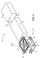
- FIG. 4 is an exploded perspective view of container portion 34, which further includes liner 54 and spool assembly 56.
- outer casing 40 includes interior region 58 and bottom opening 60, where bottom opening 60 is an enclosable opening through which liner 54 and spool assembly 56 may be inserted, thereby retaining liner 54 and spool assembly 56 within interior region 58.
- Liner 54 is a moisture-sealing barrier that is disposed within outer casing 40. Suitable materials for liner 54 include polymeric materials, metal foils, and combinations thereof. In alternative embodiments, outer casing 40 and liner 54 may be replaced with one or more layers that provides structural integrity and/or moisture resistance.
- Spool assembly 56 is shown in an exploded view along axis 62, and includes spool frame 64 and filament spool 66.
- Spool frame 64 includes frame components 64a and 64b, which may be secured together on opposing sides of filament spool 66 to rotatably secure filament spool 66 therebetween.
- Filament spool 66 is a rotatable spool that contains a supply of the build material filament for building 3D object 20.
- the build material filament is wound onto filament spool 66, and filament spool 66 is rotatably secured within spool frame 64. A portion of the build material filament is then fed through liner 54 and outer casing 40, and into tube connector 44 (shown in FIGS.
- Spool assembly 56 is then inserted within liner 54 and outer casing 40.
- interior region 58 of outer casing 40 is dried to substantially remove moisture from within interior region 58. This may be performed by placing consumable assembly 18 in a dry environment (e.g., a dry-air oven), and/or with the use of desiccant packages inserted within container portion 34. Additionally, a dry inert gas (e.g., argon and nitrogen) may be introduced into interior region 58. Liner 54 and outer casing 40 are then sealed closed to prevent moisture from entering container portion 34 during transportation and storage.
- a dry inert gas e.g., argon and nitrogen
- the filament may be provided in non-spooled arrangements.
- spool assembly 56 may be omitted, and alternative filament supply structures may be used depending on the filament packing arrangement.
- the filament may be coiled or bundled in container portion 34 without the use of filament supply structures.
- FIG. 5 is a front perspective view of consumable assembly 118, which is an alternative embodiment to consumable assembly 18, and respective reference labels are increased by "100".
- pump portion 138 further includes drive motor 168, which is secured to casing 146 and is engaged with drive mechanism 148.
- drive motor 168 may be used in lieu of drive motor 32 (shown in FIG. 1 ), and drive motor 32 may be omitted from system 12 (shown in FIG. 1 ).
- drive motor 168 is a component of consumable assembly 18, and may be discarded or recycled with consumable assembly 18 after use.
- consumable assembly 118 also includes electrical connection 170, which extends along guide tube 136 and interconnects container portion 134 and pump portion 138.
- the data reader located in the loading bay of system 12 may also provide power to data chip 142, which may correspondingly relay the electrical power from system 12 to pump portion 138 via electrical connection 170.
- one or more components of pump portion 138 e.g., liquefier region 150 and drive motor 168) may be powered in this manner.
- controller 14 shown in FIG. 1
- controller 14 also provides command signals for drive motor 168 through data chip 142 and electrical connection 170. The use of drive motor 168 and electrical connection 170 increases the ease of operation when installing and using consumable assembly 118 with system 12.
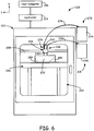
- FIG: 6 is a front view of unit 210 for building 3D objects with one or more consumable assemblies, and is an alternative embodiment to unit 10 (shown in FIG. 1 ). Respective reference labels are increased by "200".
- unit 210 further includes consumable assembly 272, which is a second consumable assembly mounted in a loading bay (not shown) of system 212.
- Consumable assembly 272 includes container portion 274, guide tube 276, and pump portion 278, which engage system 212 in the same manner as consumable assembly 218. Accordingly, pump portion 278 is also retained by extrusion mount 230, thereby providing a dual-extrusion head for system 212.
- consumable assembly 272 may contain a second material filament that may be the same or a different composition to the build material filament of consumable assembly 218.
- consumable assembly 272 contains a support material filament for building support structure 280, thereby providing vertical support along the z-axis for the layers of 3D object 220.
- consumable assembly 272 may contain the same build material filament as contained by consumable assembly 218, thereby allowing system 12 to switch from consumable assembly 218 to consumable assembly 272 when the filament supply of consumable assembly 218 runs low. This allows the build operation to continue even when consumable assembly 218 runs out of the build material filament.
- extrusion mount 230 includes a toggle mechanism to toggle between the operations of pump portion 238 and pump portion 278.
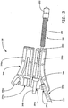
- FIGS. 7-13 are schematic illustrations of consumable assembly 318, which is similar to and is an exemplary embodiment of consumable assembly 18 (shown in FIGS. 1-4 ), where the respective reference labels are increased by "300".
- FIG. 7 is a perspective view of consumable assembly 318, where outer casing 340 of container portion 334 is fabricated from a wine box, which provides structural protection and moisture resistance.
- pump portion 338 includes bolts 382 and bracket 384.
- Bolts 382 are bolts that secure casing 346 of pump portion 338 in a closed state. Bracket 382 is secured to casing 346 via one of bolts 382, and enwraps a portion of first end 336a of guide tube 336. This positions first end 336a of guide tube 336 at a desired angle relative to casing 346 for feeding the build material filament from guide tube 336 to pump portion 338.
- FIG. 8 is a bottom view of container portion 334, where the bottom portion of outer casing 340 (i.e., opening 360) and liner 354 are open for access to spool assembly 356.
- filament 386 is wound around filament spool 366, where filament 386 may be any type of material for building a 3D object or support structure with system 12.
- suitable build materials for filament 386 include any type of extrudable thermoplastic material, such as acrylonitrile-butadiene-styrene (ABS), polycarbonate, polyphenylsulfone, polysulfone, nylon, polystyrene, amorphous polyamide, polyester, polyphenylene ether, polyurethane, polyetheretherketone, copolymers thereof, and combinations thereof.
- suitable support materials for filament 386 include silicone-doped thermoplastic materials, and water-soluble materials commercially available under the trademarks "WATERWORKS” and "SOLUBLE SUPPORTS” from Stratasys, Inc., Eden Prairie, MN.
- FIG. 9 is a perspective view of spool assembly 366 (with filament 386 omitted) where frame component 364a is removed.
- frame component 364a includes axial connection point 386a and perimeter connection points 388a
- frame component 364b includes axial connection point 386b and perimeter connection points 388b.
- filament spool 366 is mounted onto axial connection point 386b
- frame component 364a is closed over filament spool 366. Accordingly, frame portions 364a and 364b are secured together at axial connection points 386a and 386b, and at perimeter connection points 388a and 388b.
- FIG. 10 is a perspective view of spool assembly 366 (with filament 386 omitted), where frame portions 364a and 364b are secured together. As shown, when frame components 364a and 364b of spool frame 364 are secured together, filament spool 366 is rotatably secured between frame components 364a and 364b, thereby allowing filament spool 366 to freely rotate.
- FIG. 11 is a top perspective view of guide tube 336 and pump portion 338, which further illustrates the components of liquefier region 350.
- liquefier region 350 includes liquefier tube 390 and insulated heater 392.
- Liquefier tube 390 is a thermally-conductive (e.g., metallic) tube that extends between casing 346 and extrusion tip 352, and is the region in which filament 386 is melted.
- Insulated heater 392 includes a heater (e.g., wire coil heaters and thermal blocks) extending around liquefier tube 290, and a thermally-insulative sleeve extending around the heater. As discussed above, the heater is electrically connected to a power source from system 12.
- FIGS. 12 and 13 are top perspective views of guide tube 336 and pump portion 338, where casing 346 is open to illustrate the internal arrangement of casing 346.
- casing 346 includes first portion 346a, second portion 346b, and connector 392, where connector 392 interconnects first portion 346a and second portion 346b. This allows first portion 346a and second portion 346b to close together to define casing 346.
- Suitable materials for fabricating first portion 346a, second portion 346b, and connector 392 include polymeric materials, such as those discussed above for guide tube 36 (shown in FIGS. 2 and 3 ).
- First portion 346a includes drive mechanism cavity 394a and filament pathway cavity 396a
- second portion 346b includes drive mechanism cavity 394b and filament pathway cavity 396b.
- drive mechanism cavities 394a and 394b define an internal chamber for rotatably retaining drive mechanism 348
- filament pathway cavities 396a and 396b define a pathway for feeding filament 386 from guide tube 336 to liquefier tube 390.
- filament 386 is fed from guide tube 336 and into the pathway defined by filament pathway cavities 396a and 396b.
- drive mechanism 348 engages with filament 386, thereby feeding successive portions of filament 386 to liquefier tube 390.
- the heater of insulated heater 392 then melts the material of filament 386, thereby allowing the melted material to extrude from extrusion tip 352 to build a 3D object or corresponding support structure.
- the components of pump portion 338 remove several of the components from system 12 that may degrade or otherwise have reduced efficiencies over multiple extrusion runs (e.g., liquefier tube 390, insulated heater 392, drive mechanism 348, and extrusion tip 352). This allows new components to be used with each consumable assembly 318 that is loaded into system 12.
Landscapes
- Engineering & Computer Science (AREA)
- Chemical & Material Sciences (AREA)
- Materials Engineering (AREA)
- Mechanical Engineering (AREA)
- Manufacturing & Machinery (AREA)
- Physics & Mathematics (AREA)
- Optics & Photonics (AREA)
Description
- The present invention relates to extrusion-based layered deposition systems for building three-dimensional (3D) objects with rapid prototyping/manufacturing techniques. In particular, the present invention relates to consumable materials for use in extrusion-based layered deposition systems.
- An extrusion-based layered deposition system (e.g., fused deposition modeling systems developed by Stratasys, Inc., Eden Prairie, MN) is used to build a 3D object from a computer-aided design (CAD) model in a layer-by-layer manner by extruding a flowable build material. The build material is extruded through an extrusion tip carried by an extrusion head, and is deposited as a sequence of roads on a substrate in an x-y plane. The extruded build material fuses to previously deposited build material, and solidifies upon a drop in temperature. The position of the extrusion head relative to the substrate is then incremented along a z-axis (perpendicular to the x-y plane), and the process is then repeated to form a 3D object resembling the CAD model.
- Movement of the extrusion head with respect to the substrate is performed under computer control, in accordance with build data that represents the 3D object. The build data is obtained by initially slicing the CAD model of the 3D object into multiple horizontally sliced layers. Then, for each sliced layer, the host computer generates a build path for depositing roads of build material to form the 3D object.
- In fabricating 3D objects by depositing layers of build material, supporting layers or structures are typically built underneath overhanging portions or in cavities of objects under construction, which are not supported by the build material itself. A support structure may be built utilizing the same deposition techniques by which the build material is deposited. The host computer generates additional geometry acting as a support structure for the overhanging or free-space segments of the 3D object being formed. Support material is then deposited from a second nozzle pursuant to the generated geometry during the build process. The support material adheres to the build material during fabrication, and is removable from the completed 3D object when the build process is complete.
US 2003/0011103 A1 discloses an additive method for building a three-dimensional object using filament fed to an extrusion head. - The present invention relates to a consumable assembly for building 3D objects with an extrusion-based layered deposition system. The consumable assembly includes a container portion configured to retain a supply of filament, a guide tube connected to the container portion, and a pump portion connected to the guide tube, and configured to extrude a material of the filament in a flowable state.
-
-
FIG. 1 is a front perspective view of a unit for building 3D objects with a consumable assembly. -
FIG. 2 is a front perspective view of a consumable assembly. -
FIG. 3 is a rear perspective view of the consumable assembly. -
FIG. 4 is an exploded perspective view of a container portion of the consumable assembly. -
FIG. 5 is a front perspective view of a first alternative consumable assembly, which includes a drive motor. -
FIG. 6 is a front perspective view of an alternative unit for building 3D objects with multiple consumable assemblies. -
FIG. 7 is a perspective view of a second alternative consumable assembly. -
FIG. 8 is a bottom view of a container portion of the second alternative consumable assembly, where a bottom of the container portion is open. -
FIG. 9 is a perspective view of a spool assembly of the second alternative consumable assembly, where the spool assembly is partially disassembled. -
FIG. 10 is a perspective view of the spool assembly of the second alternative consumable assembly. -
FIG. 11 is a top perspective view of a guide tube and a pump portion of the second alternative consumable assembly. -
FIG. 12 is top perspective view of the guide tube and the pump portion of the second alternative consumable assembly, where a casing of the pump portion is open. -
FIG. 13 is top perspective view of the guide tube and the pump portion of the second alternative consumable assembly, where a casing of the pump portion is open and a filament is fully inserted. - Present invention concerns a consumable assembly according to appended claim 1.
FIG. 1 is a front view ofunit 10 for building 3D objects with one or more consumable assemblies, where the consumable assemblies may be discarded or recycled after use.Unit 10 includessystem 12,controller 14,host computer 16, andconsumable assembly 18, wheresystem 12 is an extrusion-based layered manufacturing system for building 3D objects (e.g., 3D object 20). Suitable systems forsystem 12 include fused deposition modeling systems developed by Stratasys, Inc., Eden Prairie, MN.Controller 14 is a computer-operated controller in signal communication withsystem 12 andhost computer 16 for controllingsystem 12.Host computer 16 is a computer-based system that interacts withsystem 12 viacontroller 14 to build3D object 20.Host computer 16 generates the build data from a CAD model (not shown) corresponding to3D object 20, and relays the build data to controller 14. -
System 12 includesbuild chamber 22,extrusion head assembly 24, andsubstrate assembly 26.Build chamber 22 is a build environment that containsextrusion head assembly 24,substrate assembly 26, and at least a portion ofconsumable assembly 18 for building3D object 20 with a build material supplied fromconsumable assembly 18. For fused deposition modeling,build chamber 22 is desirably heated to an elevated temperature to increase build efficiencies and to reduce distortions in3D object 20. -
Extrusion head assembly 24 includesx-y gantry 28,extrusion mount 30, anddrive motor 32.Extrusion mount 30 retains a portion ofconsumable assembly 18 during a build operation, and is supported byx-y gantry 28.Drive motor 32 is a motor that engagesconsumable assembly 18 during the build operation for extruding the build material fromconsumable assembly 18 based on signals provided fromcontroller 14. In this embodiment,drive motor 32 is also supported byextrusion mount 30. Accordingly, during the build operation, controller 14 directs x-y gantry to moveextrusion mount 30 and drivemotor 32 aroundbuild chamber 22 in a horizontal x-y plane, and directsdrive motor 32 to extrude the build material fromconsumable assembly 18. This selectively deposits the build material to form3D object 20 in a layer-by-layer manner onsubstrate assembly 26.Substrate assembly 26 is a moveable platform, such as the platform disclosed inDunn et al., U.S. Publication No. 2005/0173855 . Accordingly,controller 14directs substrate assembly 26 incrementally move along a z-axis during a build process, thereby allowing successive layers of3D object 20 to be built. -
Consumable assembly 18 is a disposable assembly that include a supply of build material in a filament form (not shown inFIG. 1 ), and also includes one or more components required to extrude the build material filament. As shown,consumable assembly 18 includescontainer portion 34,guide tube 36, andpump portion 38. Whilecontainer portion 34 ofconsumable assembly 18 is illustrated inFIG. 1 as being positioned at an offset location relative tosystem 12,container portion 34 is desirably mounted in a loading bay of system 12 (not shown), thereby allowingcontainer portion 34 to be securely retained tosystem 12.Container portion 34 is the portion ofconsumable assembly 18 that includes the supply of the build material filament. -
Guide tube 36 is a flexible tube that interconnectscontainer portion 34 andpump portion 38, and guides the build material filament fromcontainer portion 34 topump portion 38.Pump portion 38 is the portion ofconsumable assembly 18 that is retained byextrusion mount 30, and engages withdrive motor 32. As discussed below,pump portion 38 includes a drive mechanism (not shown inFIG. 1 ) and a liquefier (not shown inFIG. 1 ), wheredrive motor 32 engages with the drive mechanism to feed successive portions of the filament to the liquefier. The successive portions of the filament are then melted within the liquefier and extruded frompump portion 38 to build3D object 20 onsubstrate assembly 26. - As discussed above,
consumable assembly 18 may be discarded, recycled, or otherwise handled after the supply of the build material filament is emptied fromcontainer portion 34. Afterconsumable assembly 18 is depleted,pump portion 38 is removed fromextrusion mount 30 andconsumable assembly 18 is removed from the loading bay ofsystem 12. A newconsumable assembly 18 may then be mounted in the loading bay, and thepump portion 38 of the newconsumable assembly 18 may be inserted intoextrusion mount 30 for a subsequent build operation. As discussed below, the use ofconsumable assembly 18 removes several of the components fromsystem 12 that may degrade or otherwise have reduced efficiencies over multiple extrusion runs (e.g., liquefier tubes, filament drive mechanisms, and extrusion tips). This allows new components to be used with eachconsumable assembly 18 that is loaded intosystem 12. - In an alternative embodiment,
system 12 may be a component of a machine (not shown) that performs non-rapid prototyping/manufacturing processes. For example,system 12 may be part of a machine that performs milling or sheet metal forming, wheresystem 12 is configured to deposit layers of the build material onto one or more portions of the milled/formed parts. Accordingly,system 12 may be part of a larger assembly system that performs multiple steps to form parts in a continuous or batch manner. -
FIGS. 2 and3 are respectively front and rear perspective views ofconsumable assembly 18. As shown,container portion 34 ofconsumable assembly 18 includesouter casing 40,data chip 42, andtube connector 44.Outer casing 40 is an encasement structure that retains the supply of the build material filament (not shown inFIGS. 2 or3 ).Outer casing 40 is desirably a rigid or partially-rigid structure to protect the retained filament from physical damage (e.g., during transit). Whileouter casing 40 is shown as a rectangular package,outer casing 40 may alternatively exhibit a variety of different geometric shapes (e.g., cylindrical) to accommodate a variety of different loading bays for system 12 (shown inFIG. 1 ). Due to the consumable nature ofconsumable assembly 18,outer casing 40 is desirably fabricated from one or more lost-cost materials that may discarded or recycled. Examples of suitable materials forouter casing 40 include polymeric materials (e.g., polyethylenes), thin-film metals (e.g., aluminum-based sheets and foils), paper-based materials (e.g., paper, cardboard, and boxboard), and combinations thereof. In one embodiment,outer casing 40 is a package commercially available under the trademark "TETRA PAK" from Tetra Pak International SA, Switzerland. -
Data chip 42 is an integrated circuit chip that engages with a data reader located in the loading bay ofsystem 12. This allowssystem 12 to determine the type and amount of build material filament that remains inconsumable assembly 18.Data chip 42 is also suitable for measuring the amount of filament fed tosystem 12 fromcontainer portion 34 during a build operation. Suitable integrated circuit chips fordata chip 42, and suitable techniques for using the integrated circuit chips, include those disclosed in Swanson et al.,U.S. Patent No. 6,776,602 .Tube connector 44 is a connection point that is secured to guidetube 36, thereby allowing the build material filament to be fed to guidetube 36. In one embodiment,outer casing 40,tube connector 44, and guidetube 36 provide a moisture seal that prevents the transmission of moisture from external environments to locations withincontainer portion 34 or guidetube 36. This allows moisture-sensitive build materials to be used for building 3D objects (e.g., 3D object 20). -
Guide tube 36 is a flexible tube that includesfirst end 36a andsecond end 36b for interconnectingcontainer portion 34 andpump portion 38. As shown,first end 36a is connected totube connector 44, andsecond end 36b is connected to pumpportion 38.Guide tube 36 desirably has a length betweenfirst end 36a andsecond end 36b that allowspump portion 38 to move around in a horizontal x-y plane withinbuild chamber 22 of system 12 (shown inFIG. 1 ) whilecontainer portion 34 is mounted in the loading bay ofsystem 12. Additionally, guidetube 36 is desirably flexible enough to allowpump portion 38 to move around in the horizontal x-y plane withinbuild chamber 22 without substantial biasing resistance. Examples of suitable materials forguide tube 36 include polyethylenes, polyvinylchlorides, fluoropolymers, polyamides, nylons, and combinations thereof. In embodiments in which buildchamber 22 is heated during the build operation, guidetube 36 is also desirably thermally resistant to the temperature ofbuild chamber 22, thereby preventing guide tube from thermally degrading during the build operation. As discussed below, in some embodiments, guidetube 36 may include electrical connections for one or more components of pump portions 38 (e.g., for heaters, temperature sensors, and drive motors). -
Pump portion 38 is the extruder portion ofconsumable assembly 18, and includescasing 46,drive mechanism 48,liquefier region 50, andextrusion tip 52.Casing 46 is a protective casing secured to guidetube 36 for retainingguide tube 36 to pumpportion 38.Drive mechanism 48 is a filament drive mechanism that engages with drive motor 32 (shown inFIG. 1 ) (e.g., a worm gear).Liquefier region 50 is the region in which the build material filament is melted via a thermal profile along the length of theliquefier region 50.Extrusion tip 52 is the component ofpump portion 38 through which the melted build material extrudes to build3D object 20.Pump portion 38 desirably exhibits dimensions that match the internal dimensions of extrusion mount 30 (shown inFIG. 1 ). This allowspump portion 38 to be readily installed in extrusion mount 30 (shown inFIG. 1 ) without extensive installation and calibration requirements. In one embodiment,pump portion 38 also includes an electrical connection, thereby allowingliquefier region 50 to receive electrical power fromsystem 12. - During a build operation, drive
motor 32 causes drivemechanism 48 to feed successive segments of the build material filament fromcontainer portion 34, throughguide tube 36, and intoliquefier region 50. While passing throughliquefier region 50, the build material filament melts, and is extruded throughextrusion tip 52. While the build material filament melts withinliquefier region 50, the successive segments of the build material filament function as a piston to press the melted build material throughliquefier region 50 andextrusion tip 52. When the build operation is complete, drivemotor 32 anddrive mechanism 48 stop feeding the successive segments of the build material filament. At this point, ifconsumable assembly 18 is ready for removal,pump head 38 is removed fromextrusion mount 30, andconsumable assembly 18 is removed from the loading bay ofsystem 12.Consumable assembly 18 may then be discarded, recycled, or otherwise handled. -
FIG. 4 is an exploded perspective view ofcontainer portion 34, which further includesliner 54 andspool assembly 56. As shown,outer casing 40 includesinterior region 58 andbottom opening 60, wherebottom opening 60 is an enclosable opening through whichliner 54 andspool assembly 56 may be inserted, thereby retainingliner 54 andspool assembly 56 withininterior region 58.Liner 54 is a moisture-sealing barrier that is disposed withinouter casing 40. Suitable materials forliner 54 include polymeric materials, metal foils, and combinations thereof. In alternative embodiments,outer casing 40 andliner 54 may be replaced with one or more layers that provides structural integrity and/or moisture resistance. -
Spool assembly 56 is shown in an exploded view alongaxis 62, and includesspool frame 64 andfilament spool 66.Spool frame 64 includesframe components filament spool 66 to rotatablysecure filament spool 66 therebetween.Filament spool 66 is a rotatable spool that contains a supply of the build material filament for building3D object 20. During assembly ofconsumable assembly 18, the build material filament is wound ontofilament spool 66, andfilament spool 66 is rotatably secured withinspool frame 64. A portion of the build material filament is then fed throughliner 54 andouter casing 40, and into tube connector 44 (shown inFIGS. 2 and3 ) and guide tube 36 (shown inFIGS. 2 and3 ).Spool assembly 56 is then inserted withinliner 54 andouter casing 40. In one embodiment,interior region 58 ofouter casing 40 is dried to substantially remove moisture from withininterior region 58. This may be performed by placingconsumable assembly 18 in a dry environment (e.g., a dry-air oven), and/or with the use of desiccant packages inserted withincontainer portion 34. Additionally, a dry inert gas (e.g., argon and nitrogen) may be introduced intointerior region 58.Liner 54 andouter casing 40 are then sealed closed to prevent moisture from enteringcontainer portion 34 during transportation and storage. - In alternative embodiments, the filament may be provided in non-spooled arrangements. In these embodiment,
spool assembly 56 may be omitted, and alternative filament supply structures may be used depending on the filament packing arrangement. In further alternative embodiments, the filament may be coiled or bundled incontainer portion 34 without the use of filament supply structures. -
FIG. 5 is a front perspective view ofconsumable assembly 118, which is an alternative embodiment toconsumable assembly 18, and respective reference labels are increased by "100". In this embodiment,pump portion 138 further includesdrive motor 168, which is secured tocasing 146 and is engaged withdrive mechanism 148. As such, drivemotor 168 may be used in lieu of drive motor 32 (shown inFIG. 1 ), and drivemotor 32 may be omitted from system 12 (shown inFIG. 1 ). Accordingly, in this embodiment, drivemotor 168 is a component ofconsumable assembly 18, and may be discarded or recycled withconsumable assembly 18 after use. - As further shown in
FIG. 5 ,consumable assembly 118 also includeselectrical connection 170, which extends alongguide tube 136 and interconnectscontainer portion 134 andpump portion 138. In this embodiment, the data reader located in the loading bay ofsystem 12 may also provide power todata chip 142, which may correspondingly relay the electrical power fromsystem 12 to pumpportion 138 viaelectrical connection 170. Accordingly, one or more components of pump portion 138 (e.g.,liquefier region 150 and drive motor 168) may be powered in this manner. In this embodiment, controller 14 (shown inFIG. 1 ) also provides command signals fordrive motor 168 throughdata chip 142 andelectrical connection 170. The use ofdrive motor 168 andelectrical connection 170 increases the ease of operation when installing and usingconsumable assembly 118 withsystem 12. -
FIG: 6 is a front view ofunit 210 for building 3D objects with one or more consumable assemblies, and is an alternative embodiment to unit 10 (shown inFIG. 1 ). Respective reference labels are increased by "200". As shown inFIG. 6 ,unit 210 further includesconsumable assembly 272, which is a second consumable assembly mounted in a loading bay (not shown) ofsystem 212.Consumable assembly 272 includescontainer portion 274,guide tube 276, andpump portion 278, which engagesystem 212 in the same manner asconsumable assembly 218. Accordingly,pump portion 278 is also retained byextrusion mount 230, thereby providing a dual-extrusion head forsystem 212. As such,consumable assembly 272 may contain a second material filament that may be the same or a different composition to the build material filament ofconsumable assembly 218. In one embodiment,consumable assembly 272 contains a support material filament for buildingsupport structure 280, thereby providing vertical support along the z-axis for the layers of3D object 220. In an alternative embodiment,consumable assembly 272 may contain the same build material filament as contained byconsumable assembly 218, thereby allowingsystem 12 to switch fromconsumable assembly 218 toconsumable assembly 272 when the filament supply ofconsumable assembly 218 runs low. This allows the build operation to continue even whenconsumable assembly 218 runs out of the build material filament. In one embodiment,extrusion mount 230 includes a toggle mechanism to toggle between the operations ofpump portion 238 andpump portion 278. -
FIGS. 7-13 are schematic illustrations ofconsumable assembly 318, which is similar to and is an exemplary embodiment of consumable assembly 18 (shown inFIGS. 1-4 ), where the respective reference labels are increased by "300".FIG. 7 is a perspective view ofconsumable assembly 318, whereouter casing 340 ofcontainer portion 334 is fabricated from a wine box, which provides structural protection and moisture resistance. As further shown,pump portion 338 includesbolts 382 andbracket 384.Bolts 382 are bolts thatsecure casing 346 ofpump portion 338 in a closed state.Bracket 382 is secured tocasing 346 via one ofbolts 382, and enwraps a portion offirst end 336a ofguide tube 336. This positionsfirst end 336a ofguide tube 336 at a desired angle relative tocasing 346 for feeding the build material filament fromguide tube 336 to pumpportion 338. -
FIG. 8 is a bottom view ofcontainer portion 334, where the bottom portion of outer casing 340 (i.e., opening 360) andliner 354 are open for access tospool assembly 356. As shown,filament 386 is wound aroundfilament spool 366, wherefilament 386 may be any type of material for building a 3D object or support structure withsystem 12. Examples of suitable build materials forfilament 386 include any type of extrudable thermoplastic material, such as acrylonitrile-butadiene-styrene (ABS), polycarbonate, polyphenylsulfone, polysulfone, nylon, polystyrene, amorphous polyamide, polyester, polyphenylene ether, polyurethane, polyetheretherketone, copolymers thereof, and combinations thereof. Examples of suitable support materials forfilament 386 include silicone-doped thermoplastic materials, and water-soluble materials commercially available under the trademarks "WATERWORKS" and "SOLUBLE SUPPORTS" from Stratasys, Inc., Eden Prairie, MN. -
FIG. 9 is a perspective view of spool assembly 366 (withfilament 386 omitted) whereframe component 364a is removed. As shown,frame component 364a includesaxial connection point 386a andperimeter connection points 388a, andframe component 364b includesaxial connection point 386b and perimeter connection points 388b. During assembly,filament spool 366 is mounted ontoaxial connection point 386b, andframe component 364a is closed overfilament spool 366. Accordingly,frame portions axial connection points -
FIG. 10 is a perspective view of spool assembly 366 (withfilament 386 omitted), whereframe portions frame components spool frame 364 are secured together,filament spool 366 is rotatably secured betweenframe components filament spool 366 to freely rotate. -
FIG. 11 is a top perspective view ofguide tube 336 andpump portion 338, which further illustrates the components ofliquefier region 350. As shown,liquefier region 350 includesliquefier tube 390 andinsulated heater 392.Liquefier tube 390 is a thermally-conductive (e.g., metallic) tube that extends betweencasing 346 andextrusion tip 352, and is the region in which filament 386 is melted.Insulated heater 392 includes a heater (e.g., wire coil heaters and thermal blocks) extending around liquefier tube 290, and a thermally-insulative sleeve extending around the heater. As discussed above, the heater is electrically connected to a power source fromsystem 12. -
FIGS. 12 and13 are top perspective views ofguide tube 336 andpump portion 338, wherecasing 346 is open to illustrate the internal arrangement ofcasing 346. As shown inFIG. 12 , casing 346 includesfirst portion 346a,second portion 346b, andconnector 392, whereconnector 392 interconnectsfirst portion 346a andsecond portion 346b. This allowsfirst portion 346a andsecond portion 346b to close together to definecasing 346. Suitable materials for fabricatingfirst portion 346a,second portion 346b, andconnector 392 include polymeric materials, such as those discussed above for guide tube 36 (shown inFIGS. 2 and3 ).First portion 346a includesdrive mechanism cavity 394a andfilament pathway cavity 396a, andsecond portion 346b includesdrive mechanism cavity 394b andfilament pathway cavity 396b. Whenfirst portion 346a andsecond portion 346b are closed together, drivemechanism cavities drive mechanism 348, andfilament pathway cavities filament 386 fromguide tube 336 toliquefier tube 390. - As further shown in
FIG. 12 ,filament 386 is fed fromguide tube 336 and into the pathway defined byfilament pathway cavities FIG. 13 , whilefilament 386 is disposed in the pathway,drive mechanism 348 engages withfilament 386, thereby feeding successive portions offilament 386 toliquefier tube 390. The heater ofinsulated heater 392 then melts the material offilament 386, thereby allowing the melted material to extrude fromextrusion tip 352 to build a 3D object or corresponding support structure. As discussed above, the components ofpump portion 338 remove several of the components fromsystem 12 that may degrade or otherwise have reduced efficiencies over multiple extrusion runs (e.g.,liquefier tube 390,insulated heater 392,drive mechanism 348, and extrusion tip 352). This allows new components to be used with eachconsumable assembly 318 that is loaded intosystem 12.
Claims (10)
- A consumable assembly (18, 118, 272, 318) for use in an extrusion-based layered deposition system (12), the consumable assembly (18, 118, 272, 318) comprising:a container portion (34, 274, 334) configured to retain a supply of filament wherein the container portion (34, 274, 334) is offset from the extrusion-based layered deposition system (12); a pump portion;a guide tube (36, 276, 336) interconnecting the pump portion (38, 238, 338) and the container portion (34, 274, 334), wherein the guide tube (36, 276, 336) is configured to guide the filament from the container portion (34, 274, 334) to the pump portion (38, 238, 338);said pump portion (38, 238, 338) being configured to be removably inserted in a mount (30, 230) of the extrusion-based layered deposition system (12) to extrude the filament in a molten state, wherein the mount is disposed in a build chamber of the extrusion-based layered deposition system, the pump portion (38, 238, 338) comprising:a casing connected to the guide tube, the casing defining an inner pathway for guiding the filament from the guide tube;a drive mechanism (48, 348) retained by the casing, and configured to feed successive portions of the filament and a motor configured to operate the drive mechanism;a liquefier region (50) including a liquefier tube (290, 390) and configured to at least partially melt the successive portions of the filament fed by the drive mechanism (48, 348) configured to feed successive portions of the filament to provide the filament in the molten state;a heater (392) configured to heat at least a portion of the liquefier tube, thereby at least partially melting the successive portions of the filament fed by the drive mechanism to provide the material of the filament in the molten state;an extrusion tip (52, 352) disposed downstream from the heater component and configured to provide an exit location for extruding the material of the filament in the molten state;an electrical connection (170) between the container portion and the pump portion configured to receive electrical power from the extrusion- based layered deposition system (12) when the pump portion (38, 238, 338) is inserted in the mount; andwherein the pump portion (38, 238, 338) is removable from the mount such that the pump portion (38, 238, 338), the guide tube (36, 276, 336), and the container portion (34, 274, 334) are removable together from the extrusion-based layered deposition system (12).
- The consumable (18 118, 272, 318) assembly of claim 1, wherein the container portion (34, 274, 334) comprises:an outer casing (40, 340);at least one liner (54, 354) disposed within the outer casing (40, 340);a spool assembly (56, 356) disposed within the at least one liner (54, 354), the spool assembly (56, 356) being the component of the container portion (34, 274, 334) that retains the supply of the filament;at least one data chip (42, 142) configured to communicate with an extrusion-based layered deposition system (12) when the consumable assembly (18 118, 272, 318) is loaded to the extrusion-based layered deposition system (12); anda tube connection configured to provide an access point for feeding the filament from the spool assembly (56, 356).
- The consumable assembly (18 118, 272, 318) of claim 1, wherein the mount (30, 230) is positioned in a build chamber (22) of the extrusion-based layered deposition system (12).
- The consumable assembly (18 118, 272, 318) of any preceding claim, and further comprising the supply of filament, wherein the filament comprises:a first portion being the portion of the filament that is retained in the container portion (34, 274, 334);a second portion extending through the guide tube (36, 276, 336); anda third portion extending at least partially through the extruder portion (38, 238, 338).
- The consumable assembly (18 118, 272, 318) of claim 4, wherein the drive mechanism (48, 348) is engaged with the third portion of the filament.
- The consumable assembly (18 118, 272, 318) of claim 1, wherein the extruder portion (38, 238, 338) further comprises a component selected from the group consisting of a liquefier tube (290, 390), a heater (392), a thermally-insulative sleeve, an extrusion tip (52, 352), a motor (32, 168), a temperature sensor, a toggle mechanism, and combinations thereof.
- A method for building a three-dimensional object with an extrusion-based layered deposition system (12) having a mount (30, 230) for a consumable assembly (18, 118, 272, 318) as recited in claim 1, the method comprising:loading the container portion (34, 274, 334) of the consumable assembly (18, 118, 272, 318) into a loading bay of the extrusion-based layered deposition system (12);placing the container portion (34, 274, 334) of the consumable assembly (18 118, 272, 318) at a location offset from the mount (30, 230);passing a guide tube (36, 276, 336) of the consumable assembly (f18, 118, 272, 318) to a build chamber (22) of the extrusion-based layered deposition system (12);inserting the pump portion (38, 238, 338) of the consumable assembly (18, 118, 272, 318) into the mount (30, 230);feeding successive portions of a filament from the container portion (34, 274, 334), through the guide tube (36, 276, 336) and to the pump portion (38, 238, 338);at least partially melting the successively fed portions of the filament in the pump (38, 238, 338) portion to form an extrudable material;extruding the extruduable material into the build chamber (22) in a layer by layer manner to form the three dimensional object.
- The method of claim 7, and further comprising:unloading the first consumable assembly (18, 118, 272, 318) from the extrusion-based layered deposition system (12) when the supply of the filament is at least partially consumed; andloading a second consumable assembly (18, 118, 272, 318) to the extrusion-based layered deposition system (12).
- The method of claim 7, wherein the consumable assembly (18 118, 272, 318) is a first consumable assembly (18, 118, 272, 318), the method further comprising:loading a container portion (34, 274, 334) of a second consumable assembly (18, 118, 272, 318) into a loading bad of the extrusion-based layered deposition system while the first consumable assembly (118, 272, 318) remains loaded in the loading bay;passing a guide tube (36, 276, 336) of the second consumable assembly (18, 118, 272, 318) to the build chamber (22);inserting the pump portion (38, 238, 338) of the second consumable assembly (18, 118, 272, 318) into the mount (30, 230) while the pump portion (38, 238, 338) of the first consumable assembly (18, 118, 272, 318) is inserted in the mount (30, 230);feeding successive portions of a second filament from the container portion (34, 274, 334) of the second consumable assembly (18, 118, 272, 318), through the guide tube and to the pump portion;at least partially melting the successively fed portions of the second filament in the pump portion (38, 238, 338) to form a second extrudable material;extruding the second extruduable material into the build chamber (22) in a layer by layer manner to form the three dimensional object.
- The method of claims 7, 8, or 9, wherein the container portion (34, 274, 334) of the second consumable assembly (18, 118, 272, 318) comprises:an outer casing (40, 340);at least one liner disposed (54, 354) within the outer casing (40, 340); anda spool assembly (56, 356) disposed within the at least one liner (54, 354), the spool assembly (56, 356) being the component of the container portion (34, 274, 334) that retains the first portion of the filament;at least one data chip (42, 142) configured to communicate with an extrusion-based layered deposition system (12) when the consumable assembly (18 118, 272, 318) is loaded to the extrusion-based layered deposition system (12); anda tube connection configured to provide an access point for feeding the filament from the spool assembly (56, 356).
Applications Claiming Priority (2)
| Application Number | Priority Date | Filing Date | Title |
|---|---|---|---|
| US1039908P | 2008-01-08 | 2008-01-08 | |
| PCT/US2009/000052 WO2009088995A1 (en) | 2008-01-08 | 2009-01-07 | Consumable assembly for use in extrusion-based layered deposition systems |
Publications (3)
| Publication Number | Publication Date |
|---|---|
| EP2243097A1 EP2243097A1 (en) | 2010-10-27 |
| EP2243097A4 EP2243097A4 (en) | 2017-10-25 |
| EP2243097B1 true EP2243097B1 (en) | 2020-07-15 |
Family
ID=40853401
Family Applications (1)
| Application Number | Title | Priority Date | Filing Date |
|---|---|---|---|
| EP09701222.3A Active EP2243097B1 (en) | 2008-01-08 | 2009-01-07 | Consumable assembly for use in extrusion-based layered deposition systems |
Country Status (11)
| Country | Link |
|---|---|
| US (5) | US8403658B2 (en) |
| EP (1) | EP2243097B1 (en) |
| JP (1) | JP5618834B2 (en) |
| KR (1) | KR20100113097A (en) |
| CN (1) | CN101911084B (en) |
| AU (1) | AU2009204492B2 (en) |
| BR (1) | BRPI0906506A2 (en) |
| CA (1) | CA2711364A1 (en) |
| HK (1) | HK1149809A1 (en) |
| RU (1) | RU2479020C2 (en) |
| WO (1) | WO2009088995A1 (en) |
Families Citing this family (117)
| Publication number | Priority date | Publication date | Assignee | Title |
|---|---|---|---|---|
| RU2479020C2 (en) | 2008-01-08 | 2013-04-10 | Стратасис, Инк. | Replaceable cartridge for system of layer-by-layer extrusion settlement |
| US20110121476A1 (en) | 2009-11-19 | 2011-05-26 | Stratasys, Inc. | Encoded consumable materials and sensor assemblies for use in additive manufacturing systems |
| US20110117268A1 (en) * | 2009-11-19 | 2011-05-19 | Stratasys, Inc. | Consumable materials having encoded markings for use with direct digital manufacturing systems |
| WO2011112760A2 (en) | 2010-03-11 | 2011-09-15 | Stratasys, Inc. | Optical encoder |
| US8663533B2 (en) | 2010-12-22 | 2014-03-04 | Stratasys, Inc. | Method of using print head assembly in fused deposition modeling system |
| US9238329B2 (en) | 2010-12-22 | 2016-01-19 | Stratasys, Inc. | Voice coil mechanism for use in additive manufacturing system |
| WO2012088253A1 (en) | 2010-12-22 | 2012-06-28 | Stratasys, Inc. | Print head assembly for use in fused deposition modeling system |
| US8647102B2 (en) | 2010-12-22 | 2014-02-11 | Stratasys, Inc. | Print head assembly and print head for use in fused deposition modeling system |
| US8419996B2 (en) | 2010-12-22 | 2013-04-16 | Stratasys, Inc. | Print head assembly for use in fused deposition modeling system |
| US8512024B2 (en) * | 2011-01-20 | 2013-08-20 | Makerbot Industries, Llc | Multi-extruder |
| US8460755B2 (en) | 2011-04-07 | 2013-06-11 | Stratasys, Inc. | Extrusion-based additive manufacturing process with part annealing |
| US8818544B2 (en) | 2011-09-13 | 2014-08-26 | Stratasys, Inc. | Solid identification grid engine for calculating support material volumes, and methods of use |
| US9108360B2 (en) | 2011-09-23 | 2015-08-18 | Stratasys, Inc. | Gantry assembly for use in additive manufacturing system |
| US8985497B2 (en) | 2011-12-22 | 2015-03-24 | Stratasys, Inc. | Consumable assembly with payout tube for additive manufacturing system |
| US9073263B2 (en) | 2011-12-22 | 2015-07-07 | Stratasys, Inc. | Spool assembly for additive manufacturing system, and methods of manufacture and use thereof |
| US9050788B2 (en) | 2011-12-22 | 2015-06-09 | Stratasys, Inc. | Universal adapter for consumable assembly used with additive manufacturing system |
| US9321608B2 (en) | 2011-12-22 | 2016-04-26 | Stratasys, Inc. | Spool assembly with locking mechanism for additive manufacturing system, and methods of use thereof |
| US9205690B2 (en) | 2012-03-16 | 2015-12-08 | Stratasys, Inc. | Automated calibration method for additive manufacturing system, and method of use thereof |
| US9108450B2 (en) * | 2012-05-04 | 2015-08-18 | Makerbot Industries, Llc | Voice-controlled three-dimensional fabrication system |
| US9636868B2 (en) | 2012-08-16 | 2017-05-02 | Stratasys, Inc. | Additive manufacturing system with extended printing volume, and methods of use thereof |
| US9168697B2 (en) | 2012-08-16 | 2015-10-27 | Stratasys, Inc. | Additive manufacturing system with extended printing volume, and methods of use thereof |
| US9327350B2 (en) | 2012-08-16 | 2016-05-03 | Stratasys, Inc. | Additive manufacturing technique for printing three-dimensional parts with printed receiving surfaces |
| US10029415B2 (en) * | 2012-08-16 | 2018-07-24 | Stratasys, Inc. | Print head nozzle for use with additive manufacturing system |
| US9174388B2 (en) | 2012-08-16 | 2015-11-03 | Stratasys, Inc. | Draw control for extrusion-based additive manufacturing systems |
| US9511547B2 (en) | 2012-08-16 | 2016-12-06 | Stratasys, Inc. | Method for printing three-dimensional parts with additive manufacturing systems using scaffolds |
| US11020899B2 (en) | 2012-08-16 | 2021-06-01 | Stratasys, Inc. | Additive manufacturing system with extended printing volume, and methods of use thereof |
| US9744722B2 (en) | 2012-11-21 | 2017-08-29 | Stratasys, Inc. | Additive manufacturing with polyamide consumable materials |
| US9527242B2 (en) | 2012-11-21 | 2016-12-27 | Stratasys, Inc. | Method for printing three-dimensional parts wtih crystallization kinetics control |
| US9592530B2 (en) | 2012-11-21 | 2017-03-14 | Stratasys, Inc. | Additive manufacturing with polyamide consumable materials |
| US9102098B2 (en) | 2012-12-05 | 2015-08-11 | Wobbleworks, Inc. | Hand-held three-dimensional drawing device |
| US9321609B2 (en) | 2012-12-07 | 2016-04-26 | Stratasys, Inc. | Filament drive mechanism for use in additive manufacturing system |
| US9233506B2 (en) | 2012-12-07 | 2016-01-12 | Stratasys, Inc. | Liquefier assembly for use in additive manufacturing system |
| US9090428B2 (en) | 2012-12-07 | 2015-07-28 | Stratasys, Inc. | Coil assembly having permeable hub |
| US9216544B2 (en) | 2012-12-21 | 2015-12-22 | Stratasys, Inc. | Automated additive manufacturing system for printing three-dimensional parts, printing farm thereof, and method of use thereof |
| US8961167B2 (en) | 2012-12-21 | 2015-02-24 | Stratasys, Inc. | Automated additive manufacturing system for printing three-dimensional parts, printing farm thereof, and method of use thereof |
| US9421713B2 (en) | 2013-03-08 | 2016-08-23 | Stratasys, Inc. | Additive manufacturing method for printing three-dimensional parts with purge towers |
| US10093039B2 (en) | 2013-03-08 | 2018-10-09 | Stratasys, Inc. | Three-dimensional parts having interconnected Hollow patterns, method of manufacturing and method of producing composite part |
| US9399320B2 (en) | 2013-03-08 | 2016-07-26 | Stratasys, Inc. | Three-dimensional parts having interconnected hollow patterns, and method for generating and printing thereof |
| US9527240B2 (en) | 2013-03-15 | 2016-12-27 | Stratasys, Inc. | Additive manufacturing system and method for printing three-dimensional parts using velocimetry |
| US9802360B2 (en) | 2013-06-04 | 2017-10-31 | Stratsys, Inc. | Platen planarizing process for additive manufacturing system |
| US20140363532A1 (en) * | 2013-06-10 | 2014-12-11 | Kirk W. Wolfgram | Multiple color extrusion type three dimensional printer |
| CN103341961B (en) * | 2013-06-17 | 2016-07-06 | 耿得力 | A kind of hot melt material extrusion device |
| US9523934B2 (en) | 2013-07-17 | 2016-12-20 | Stratasys, Inc. | Engineering-grade consumable materials for electrophotography-based additive manufacturing |
| US9714318B2 (en) | 2013-07-26 | 2017-07-25 | Stratasys, Inc. | Polyglycolic acid support material for additive manufacturing systems |
| CN103395290A (en) * | 2013-08-07 | 2013-11-20 | 苏州江南嘉捷机电技术研究院有限公司 | Three-dimensional printer with internal consumable device |
| US9950474B2 (en) | 2013-09-13 | 2018-04-24 | Statasys, Inc. | Additive manufacturing system and process with precision substractive technique |
| US10201931B2 (en) | 2013-10-04 | 2019-02-12 | Stratasys, Inc. | Additive manufacturing system and process with material flow feedback control |
| WO2015050958A2 (en) | 2013-10-04 | 2015-04-09 | Stratasys, Inc. | Liquefier assembly for additive manufacturing systems, and methods of use thereof |
| US10086564B2 (en) | 2013-10-04 | 2018-10-02 | Stratsys, Inc. | Additive manufacturing process with dynamic heat flow control |
| US9327447B2 (en) | 2013-10-04 | 2016-05-03 | Stratasys, Inc. | Liquefier assembly for additive manufacturing systems, and methods of use thereof |
| US10131131B2 (en) | 2013-10-04 | 2018-11-20 | Stratasys, Inc. | Liquefier assembly with multiple-zone plate heater assembly |
| US9744730B2 (en) | 2013-11-22 | 2017-08-29 | Stratasys, Inc. | Magnetic platen assembly for additive manufacturing system |
| GB2521600A (en) * | 2013-12-18 | 2015-07-01 | Skf Ab | A building block for a mechanical construction |
| USD749157S1 (en) * | 2014-01-05 | 2016-02-09 | Makerbot Industries, Llc | Three-dimensional printer extruder carriage |
| TWI486263B (en) * | 2014-01-06 | 2015-06-01 | 三緯國際立體列印科技股份有限公司 | Printing head module |
| CA2939270A1 (en) * | 2014-02-11 | 2015-08-20 | Structur3D Printing Incorporated | Multi-material extruder and extrusion method for three-dimensional (3d) printing |
| US9636872B2 (en) | 2014-03-10 | 2017-05-02 | Stratasys, Inc. | Method for printing three-dimensional parts with part strain orientation |
| EP3143053A1 (en) | 2014-05-16 | 2017-03-22 | Stratasys, Inc. | High-temperature soluble support material for additive manufacturing |
| EP4147851B1 (en) * | 2014-06-08 | 2024-05-01 | Massivit 3D Printing Technologies Ltd. | A method for manufacture of 3d objects |
| CN105313332B (en) * | 2014-06-09 | 2020-05-05 | 联合工艺公司 | Two-part thermosetting resin additive manufacturing system |
| USD741149S1 (en) | 2014-07-21 | 2015-10-20 | Stratasys, Inc. | Filament spool |
| US10513103B2 (en) | 2014-07-22 | 2019-12-24 | Stratasys, Inc. | Ripple reduction in an additive manufacturing system |
| US11771655B2 (en) | 2014-09-08 | 2023-10-03 | University Of Central Lancashire | Solid dosage form production |
| US20160073644A1 (en) * | 2014-09-15 | 2016-03-17 | Roger Dickey | Automated processing and placement of three-dimensional food ingredients on a surface of an object |
| WO2016049642A1 (en) | 2014-09-26 | 2016-03-31 | Stratasys, Inc. | Liquefier assemblies for additive manufacturing systems, and methods of use thereof |
| US10059053B2 (en) | 2014-11-04 | 2018-08-28 | Stratasys, Inc. | Break-away support material for additive manufacturing |
| US9694545B2 (en) | 2014-12-18 | 2017-07-04 | Stratasys, Inc. | Remotely-adjustable purge station for use in additive manufacturing systems |
| US9610733B2 (en) | 2015-01-06 | 2017-04-04 | Stratasys, Inc. | Additive manufacturing with soluble build sheet and part marking |
| US20160236407A1 (en) * | 2015-02-17 | 2016-08-18 | Michael Daniel Armani | 3d printer |
| US9604827B2 (en) * | 2015-02-18 | 2017-03-28 | John Azzarelli | Mobile winch in a bag system |
| US9993955B2 (en) * | 2015-02-27 | 2018-06-12 | JuggerBot 3D, LLC | Interdependent drive system |
| WO2016171191A1 (en) * | 2015-04-20 | 2016-10-27 | Mcppイノベーション合同会社 | Shaping filament for material extrusion type three-dimensional printer, and process for producing shaped object |
| JP6047629B1 (en) * | 2015-06-23 | 2016-12-21 | ホッティーポリマー株式会社 | 3D printing device |
| US10406759B2 (en) * | 2015-08-05 | 2019-09-10 | University Of Florida Research Foundation, Inc | 3D printing mechanical hold build plate |
| JP6616134B2 (en) * | 2015-09-08 | 2019-12-04 | 東洋リビング株式会社 | Moisture-proof cabinet for 3D printer |
| US10399326B2 (en) | 2015-10-30 | 2019-09-03 | Stratasys, Inc. | In-situ part position measurement |
| DE112016004933T5 (en) | 2015-10-30 | 2018-08-16 | Stratasys, Inc. | Support plate removal for an additive manufacturing system |
| US10583646B2 (en) | 2015-10-30 | 2020-03-10 | Stratasys, Inc. | Starter piece and printing methods for additive manufacturing system |
| US10421268B2 (en) | 2015-11-18 | 2019-09-24 | Stratasys, Inc. | Filament feeding device having a capacitive filament displacement sensor for use in additive manufacturing system |
| US10518472B2 (en) * | 2015-12-08 | 2019-12-31 | Stratasys, Inc. | Thermal drying system for additive manufacturing device |
| US10471702B2 (en) | 2015-12-11 | 2019-11-12 | Stratasys, Inc. | Additive manufacturing systems and method of filling voids in 3D parts |
| US10953595B2 (en) | 2015-12-24 | 2021-03-23 | Stratasys, Inc. | Water soluble support materials for high temperature additive manufacturing applications |
| US11045997B2 (en) | 2015-12-24 | 2021-06-29 | Stratasys, Inc. | Water soluble support materials for high temperature additive manufacturing applications |
| WO2017147412A1 (en) | 2016-02-25 | 2017-08-31 | Stratasys Ltd. | Gpu material assignment for 3d printing using 3d distance fields |
| US10052813B2 (en) | 2016-03-28 | 2018-08-21 | Arevo, Inc. | Method for additive manufacturing using filament shaping |
| US10471658B2 (en) | 2016-04-18 | 2019-11-12 | Stratasys, Inc. | Sheet substrate retention device for securing a sheet substrate to a vacuum platen in an additive manufacturing system |
| US10434719B2 (en) | 2016-04-19 | 2019-10-08 | Stratasys, Inc. | Magnetically coupled print head for additive manufacturing system |
| US10926454B2 (en) * | 2016-05-20 | 2021-02-23 | Sartorius Stedim Biotech Gmbh | Dispensing device and system for biological products |
| WO2017210490A1 (en) | 2016-06-01 | 2017-12-07 | Arevo, Inc. | Localized heating to improve interlayer bonding in 3d printing |
| US10265941B2 (en) | 2016-08-15 | 2019-04-23 | Stratasys, Inc. | Heated air system for 3D printer |
| US10494219B2 (en) | 2016-08-15 | 2019-12-03 | Stratasys, Inc. | Filament loading drive in a 3D printer |
| US10513104B2 (en) | 2016-08-15 | 2019-12-24 | Stratasys, Inc. | 3D printer with coupling for attaching print head to head carriage |
| US10513107B2 (en) | 2016-08-15 | 2019-12-24 | Stratasys, Inc. | Lever tray release |
| US10442179B2 (en) * | 2016-08-15 | 2019-10-15 | Stratasys, Inc. | 3D printer with spool and material container |
| JP6538738B2 (en) | 2017-03-01 | 2019-07-03 | 本田技研工業株式会社 | Resin material heating apparatus and resin material heating method |
| WO2018163006A1 (en) * | 2017-03-05 | 2018-09-13 | Micron 3Dp Ltd. | 3d printing system for printing high melting temperature materials |
| USD888115S1 (en) | 2017-03-16 | 2020-06-23 | Stratasys, Inc. | Nozzle |
| US11911958B2 (en) | 2017-05-04 | 2024-02-27 | Stratasys, Inc. | Method and apparatus for additive manufacturing with preheat |
| WO2018217650A1 (en) | 2017-05-22 | 2018-11-29 | Arevo, Inc. | Methods and systems for three-dimensional printing of composite objects |
| US20180345650A1 (en) | 2017-05-31 | 2018-12-06 | The Regents Of The University Of Michigan | Method of additive manufacturing an internal wave sparse structure with varying geometry for localized tunable structural properties throughout a part |
| EP3655252A4 (en) | 2017-10-05 | 2021-02-24 | Hewlett-Packard Development Company, L.P. | Supply containers with alignment components |
| US10545687B1 (en) | 2017-10-31 | 2020-01-28 | Pure Storage, Inc. | Data rebuild when changing erase block sizes during drive replacement |
| CN209869406U (en) | 2017-12-29 | 2019-12-31 | 斯特塔思有限公司 | Additive manufacturing system with extended print volume |
| US10684806B2 (en) | 2017-12-29 | 2020-06-16 | Stratasys, Inc. | Method and system for automated print failure detection and re-submission |
| US11203156B2 (en) | 2018-08-20 | 2021-12-21 | NEXA3D Inc. | Methods and systems for photo-curing photo-sensitive material for printing and other applications |
| US11247387B2 (en) | 2018-08-30 | 2022-02-15 | Stratasys, Inc. | Additive manufacturing system with platen having vacuum and air bearing |
| CN113242787B (en) | 2018-11-09 | 2023-02-10 | 耐克森三维有限公司 | Three-dimensional printing system |
| CA3130312C (en) | 2019-03-18 | 2023-08-01 | NEXA3D Inc. | Method and system for additive manufacture |
| US11760001B2 (en) | 2019-03-29 | 2023-09-19 | Stratasys, Inc. | Filament supply with sealed connector for use with a 3D printer |
| US10967573B2 (en) | 2019-04-02 | 2021-04-06 | NEXA3D Inc. | Tank assembly and components thereof for a 3D printing system |
| DE102019112258A1 (en) * | 2019-05-10 | 2020-11-12 | Homag Gmbh | Packaging for packaging consumables and method of supplying consumables |
| DE102019121658A1 (en) * | 2019-08-12 | 2021-02-18 | Röchling Automotive SE & Co. KG | Apparatus with a climatic chamber arrangement for carrying out a melt layering process |
| US11485085B2 (en) | 2020-01-21 | 2022-11-01 | Stratasys, Inc. | Low pull force filament delivery system |
| JP7204245B2 (en) * | 2021-06-14 | 2023-01-16 | 秀夫 谷口 | 3D printer, hot end module for 3D printer, ejection head, and filament feeding method |
| CN115114709B (en) * | 2022-06-13 | 2024-04-19 | 安徽理工大学 | Prediction method for three-dimensional thawing deformation of subway tunnel freezing method construction stratum |
| US20240009920A1 (en) * | 2022-07-07 | 2024-01-11 | Stratasys, Inc. | 3d printer providing spool chip dock outside of spool cabinet environment and methods of use thereof |
| WO2024010581A1 (en) * | 2022-07-07 | 2024-01-11 | Stratasys, Inc. | Tethered spool assembly and methods of use thereof |
Family Cites Families (50)
| Publication number | Priority date | Publication date | Assignee | Title |
|---|---|---|---|---|
| US1906495A (en) * | 1930-10-04 | 1933-05-02 | A H Rice Company | Spool for thread |
| US2298357A (en) | 1940-10-04 | 1942-10-13 | Celanese Corp | Package support |
| US3358943A (en) * | 1966-05-09 | 1967-12-19 | Pelson Ernest | Spool construction |
| USD260514S (en) * | 1978-03-22 | 1981-09-01 | Tuscan Industries Pty. Limited | Magnetic tape cassette |
| GB2079247A (en) | 1980-07-08 | 1982-01-20 | Dollfus Mieg Et Cie | Reels for Thread |
| US4387863A (en) * | 1981-12-17 | 1983-06-14 | Western Electric Company, Inc. | Spool assembly |
| USD276527S (en) * | 1982-06-07 | 1984-11-27 | Microtek Storage Corporation | Magnetic data storage cartridge |
| USD282357S (en) * | 1983-09-30 | 1986-01-28 | Plastex Technology (Curacao) N.V. | Microfilm cartridge or similar article |
| US4657203A (en) * | 1985-10-16 | 1987-04-14 | Crellin, Inc. | Fiber optic cable reel |
| US5121329A (en) * | 1989-10-30 | 1992-06-09 | Stratasys, Inc. | Apparatus and method for creating three-dimensional objects |
| USD346379S (en) * | 1991-09-06 | 1994-04-26 | Minnesota Mining And Manufacturing Company | Housing for a single reel tape cartridge |
| USD343319S (en) * | 1991-10-23 | 1994-01-18 | Phillips Edward H | Suture cassette |
| US5503785A (en) * | 1994-06-02 | 1996-04-02 | Stratasys, Inc. | Process of support removal for fused deposition modeling |
| USD381645S (en) * | 1995-01-27 | 1997-07-29 | Imation Corp. | Housing for a single reel tape cartridge |
| USD406049S (en) * | 1995-10-17 | 1999-02-23 | Bernat Gerald J | End cap for a wire reel spool |
| US5764521A (en) | 1995-11-13 | 1998-06-09 | Stratasys Inc. | Method and apparatus for solid prototyping |
| US6085957A (en) * | 1996-04-08 | 2000-07-11 | Stratasys, Inc. | Volumetric feed control for flexible filament |
| US6070107A (en) * | 1997-04-02 | 2000-05-30 | Stratasys, Inc. | Water soluble rapid prototyping support and mold material |
| US6228923B1 (en) * | 1997-04-02 | 2001-05-08 | Stratasys, Inc. | Water soluble rapid prototyping support and mold material |
| USD408720S (en) * | 1997-09-19 | 1999-04-27 | Honeyware, Inc. | All-plastic reel for electrical extension cords |
| US5968561A (en) * | 1998-01-26 | 1999-10-19 | Stratasys, Inc. | High performance rapid prototyping system |
| US5939008A (en) * | 1998-01-26 | 1999-08-17 | Stratasys, Inc. | Rapid prototyping apparatus |
| US6022207A (en) * | 1998-01-26 | 2000-02-08 | Stratasys, Inc. | Rapid prototyping system with filament supply spool monitoring |
| KR100291953B1 (en) | 1999-03-15 | 2001-06-01 | 윤덕용 | Variable deposition manufacturing method and apparatus |
| US6776602B2 (en) * | 1999-04-20 | 2004-08-17 | Stratasys, Inc. | Filament cassette and loading system |
| EP1194274B1 (en) * | 1999-04-20 | 2017-03-22 | Stratasys, Inc. | Process for three-dimensional modeling |
| US6722872B1 (en) * | 1999-06-23 | 2004-04-20 | Stratasys, Inc. | High temperature modeling apparatus |
| RU2186681C2 (en) * | 1999-10-06 | 2002-08-10 | Шиляев Николай Иванович | Method for stratified synthesis of articles and device for its realization |
| USD436111S1 (en) * | 2000-03-28 | 2001-01-09 | Stratasys, Inc. | Filament cartridge |
| USD436021S1 (en) * | 2000-04-07 | 2001-01-09 | Arnold Stanley E | Electrical wire spool with integrated tension control bushing |
| JP2002096974A (en) * | 2000-09-22 | 2002-04-02 | Oki Electric Ind Co Ltd | Conveying reel, conveying method using it, and method of manufacturing electronic device |
| USD470498S1 (en) * | 2002-04-02 | 2003-02-18 | International Business Machines Corporation | Data cartridge |
| USD474191S1 (en) * | 2002-07-15 | 2003-05-06 | Sony Corporation | Tape cartridge |
| US6715710B1 (en) * | 2002-09-13 | 2004-04-06 | Russell Forest Products, Inc. | Self aligning stackable cable reel |
| AU2003279508A1 (en) * | 2002-11-12 | 2004-06-03 | Objet Geometries Ltd. | Three-dimensional object printing |
| USD491048S1 (en) * | 2003-01-29 | 2004-06-08 | Thermocompact | Spool |
| US6991197B2 (en) * | 2003-10-14 | 2006-01-31 | Vandor Corporation | Webbed flange for a reel |
| US7063285B1 (en) * | 2003-11-04 | 2006-06-20 | Stratasys, Inc. | Cassette device for reliable filament delivery |
| US7127309B2 (en) * | 2004-02-10 | 2006-10-24 | Stratasys, Inc. | Modeling apparatus with tray substrate |
| US7341214B2 (en) * | 2005-06-30 | 2008-03-11 | Stratasys, Inc. | Cassette spool lock |
| US7384255B2 (en) * | 2005-07-01 | 2008-06-10 | Stratasys, Inc. | Rapid prototyping system with controlled material feedstock |
| US7604470B2 (en) * | 2006-04-03 | 2009-10-20 | Stratasys, Inc. | Single-motor extrusion head having multiple extrusion lines |
| GB2438394A (en) | 2006-05-23 | 2007-11-28 | Andrew Norman Watt | Hand-held manually operated cable storage device |
| FR2902681A1 (en) | 2006-06-23 | 2007-12-28 | Air Liquide | Reel of welding wire, for supplying wire drum of arc welding torch, includes fixing system on side plate of coil for receiving and holding free end of wire to prevent uncoiling |
| USD557118S1 (en) * | 2006-12-21 | 2007-12-11 | Richmond Pattern, Llc | Molded plastic reel |
| JP4833171B2 (en) | 2007-08-24 | 2011-12-07 | 富士フイルム株式会社 | reel |
| RU2479020C2 (en) | 2008-01-08 | 2013-04-10 | Стратасис, Инк. | Replaceable cartridge for system of layer-by-layer extrusion settlement |
| USD598733S1 (en) * | 2008-10-22 | 2009-08-25 | Stratasys, Inc. | Filament spool |
| USD598922S1 (en) * | 2008-10-22 | 2009-08-25 | Stratasys, Inc. | Filament spool container |
| USD595121S1 (en) * | 2008-11-07 | 2009-06-30 | Jimmie Loyd Murphy | Tubing reel |
-
2009
- 2009-01-07 RU RU2010133228/08A patent/RU2479020C2/en active
- 2009-01-07 US US12/811,411 patent/US8403658B2/en active Active
- 2009-01-07 EP EP09701222.3A patent/EP2243097B1/en active Active
- 2009-01-07 AU AU2009204492A patent/AU2009204492B2/en not_active Ceased
- 2009-01-07 CN CN200980101836.8A patent/CN101911084B/en not_active Expired - Fee Related
- 2009-01-07 KR KR1020107017026A patent/KR20100113097A/en active IP Right Grant
- 2009-01-07 JP JP2010542259A patent/JP5618834B2/en active Active
- 2009-01-07 WO PCT/US2009/000052 patent/WO2009088995A1/en active Application Filing
- 2009-01-07 BR BRPI0906506-7A patent/BRPI0906506A2/en not_active Application Discontinuation
- 2009-01-07 CA CA2711364A patent/CA2711364A1/en not_active Abandoned
-
2011
- 2011-04-07 HK HK11103536.2A patent/HK1149809A1/en not_active IP Right Cessation
-
2013
- 2013-02-25 US US13/775,966 patent/US8808603B2/en active Active
-
2014
- 2014-05-27 US US14/287,775 patent/US8864482B2/en active Active
- 2014-09-12 US US14/485,005 patent/US9545754B2/en active Active
-
2015
- 2015-04-02 US US14/677,175 patent/US9174389B2/en active Active
Non-Patent Citations (1)
| Title |
|---|
| None * |
Also Published As
| Publication number | Publication date |
|---|---|
| EP2243097A1 (en) | 2010-10-27 |
| US20150001757A1 (en) | 2015-01-01 |
| EP2243097A4 (en) | 2017-10-25 |
| CN101911084B (en) | 2014-05-28 |
| US8403658B2 (en) | 2013-03-26 |
| US20150210008A1 (en) | 2015-07-30 |
| HK1149809A1 (en) | 2011-10-14 |
| US20100283172A1 (en) | 2010-11-11 |
| AU2009204492A1 (en) | 2009-07-16 |
| US8808603B2 (en) | 2014-08-19 |
| US20140271967A1 (en) | 2014-09-18 |
| CN101911084A (en) | 2010-12-08 |
| CA2711364A1 (en) | 2009-07-16 |
| US9174389B2 (en) | 2015-11-03 |
| US20130168892A1 (en) | 2013-07-04 |
| JP5618834B2 (en) | 2014-11-05 |
| JP2011511719A (en) | 2011-04-14 |
| WO2009088995A1 (en) | 2009-07-16 |
| RU2010133228A (en) | 2012-02-20 |
| US9545754B2 (en) | 2017-01-17 |
| KR20100113097A (en) | 2010-10-20 |
| RU2479020C2 (en) | 2013-04-10 |
| AU2009204492B2 (en) | 2013-10-03 |
| US8864482B2 (en) | 2014-10-21 |
| BRPI0906506A2 (en) | 2015-07-14 |
Similar Documents
| Publication | Publication Date | Title |
|---|---|---|
| EP2243097B1 (en) | Consumable assembly for use in extrusion-based layered deposition systems | |
| EP2231375B1 (en) | System for building three-dimensional objects containing embedded inserts, and methods of use thereof | |
| US9022769B2 (en) | Multiple-zone liquefier assembly for extrusion-based additive manufacturing systems | |
| US9050788B2 (en) | Universal adapter for consumable assembly used with additive manufacturing system | |
| EP2607057B1 (en) | Spool assembly for additive manufacturing system, and methods of manufacture and use thereof | |
| WO2014137637A1 (en) | Additive manufacturing method for printing three-dimensional parts with purge towers | |
| US20170298521A1 (en) | Filament with exterior barrier and method of producing same | |
| KR101849592B1 (en) | Three dimensional printer material with replacable nozzles | |
| US11338514B2 (en) | Protective filament guide tube for additive manufacturing system | |
| US10442179B2 (en) | 3D printer with spool and material container | |
| US20240009924A1 (en) | Tethered spool assembly and methods of use thereof | |
| EP3505328B1 (en) | Additive manufacturing system with extended printing volume, and method of use thereof | |
| JP2021075019A (en) | Modeling apparatus and modeling method | |
| US8479795B2 (en) | System and method for rapid fabrication of arbitrary three-dimensional objects | |
| US20240009920A1 (en) | 3d printer providing spool chip dock outside of spool cabinet environment and methods of use thereof | |
| US20230211553A1 (en) | Method of moving a print head between a plurality of partitioned chambers in an additive manufacturing system | |
| WO2024010581A1 (en) | Tethered spool assembly and methods of use thereof | |
| CN114585468A (en) | Methods and systems for additive manufacturing of electrical devices |
Legal Events
| Date | Code | Title | Description |
|---|---|---|---|
| PUAI | Public reference made under article 153(3) epc to a published international application that has entered the european phase |
Free format text: ORIGINAL CODE: 0009012 |
|
| 17P | Request for examination filed |
Effective date: 20100713 |
|
| AK | Designated contracting states |
Kind code of ref document: A1 Designated state(s): AT BE BG CH CY CZ DE DK EE ES FI FR GB GR HR HU IE IS IT LI LT LU LV MC MK MT NL NO PL PT RO SE SI SK TR |
|
| AX | Request for extension of the european patent |
Extension state: AL BA RS |
|
| DAX | Request for extension of the european patent (deleted) | ||
| RA4 | Supplementary search report drawn up and despatched (corrected) |
Effective date: 20170927 |
|
| RIC1 | Information provided on ipc code assigned before grant |
Ipc: G06F 19/00 20110101AFI20170921BHEP Ipc: B29C 64/118 20170101ALI20170921BHEP |
|
| STAA | Information on the status of an ep patent application or granted ep patent |
Free format text: STATUS: EXAMINATION IS IN PROGRESS |
|
| 17Q | First examination report despatched |
Effective date: 20180406 |
|
| REG | Reference to a national code |
Ref country code: DE Ref legal event code: R079 Ref document number: 602009062406 Country of ref document: DE Free format text: PREVIOUS MAIN CLASS: G06F0019000000 Ipc: B29C0064118000 |
|
| GRAP | Despatch of communication of intention to grant a patent |
Free format text: ORIGINAL CODE: EPIDOSNIGR1 |
|
| STAA | Information on the status of an ep patent application or granted ep patent |
Free format text: STATUS: GRANT OF PATENT IS INTENDED |
|
| RIC1 | Information provided on ipc code assigned before grant |
Ipc: B29C 64/118 20170101AFI20200214BHEP |
|
| INTG | Intention to grant announced |
Effective date: 20200316 |
|
| RIN1 | Information on inventor provided before grant (corrected) |
Inventor name: SWANSON, WILLIAM, J. |
|
| GRAS | Grant fee paid |
Free format text: ORIGINAL CODE: EPIDOSNIGR3 |
|
| GRAA | (expected) grant |
Free format text: ORIGINAL CODE: 0009210 |
|
| STAA | Information on the status of an ep patent application or granted ep patent |
Free format text: STATUS: THE PATENT HAS BEEN GRANTED |
|
| AK | Designated contracting states |
Kind code of ref document: B1 Designated state(s): AT BE BG CH CY CZ DE DK EE ES FI FR GB GR HR HU IE IS IT LI LT LU LV MC MK MT NL NO PL PT RO SE SI SK TR |
|
| REG | Reference to a national code |
Ref country code: GB Ref legal event code: FG4D Ref country code: CH Ref legal event code: EP |
|
| REG | Reference to a national code |
Ref country code: DE Ref legal event code: R096 Ref document number: 602009062406 Country of ref document: DE |
|
| REG | Reference to a national code |
Ref country code: IE Ref legal event code: FG4D |
|
| REG | Reference to a national code |
Ref country code: AT Ref legal event code: REF Ref document number: 1290526 Country of ref document: AT Kind code of ref document: T Effective date: 20200815 |
|
| REG | Reference to a national code |
Ref country code: LT Ref legal event code: MG4D |
|
| REG | Reference to a national code |
Ref country code: AT Ref legal event code: MK05 Ref document number: 1290526 Country of ref document: AT Kind code of ref document: T Effective date: 20200715 |
|
| REG | Reference to a national code |
Ref country code: NL Ref legal event code: MP Effective date: 20200715 |
|
| PG25 | Lapsed in a contracting state [announced via postgrant information from national office to epo] |
Ref country code: SE Free format text: LAPSE BECAUSE OF FAILURE TO SUBMIT A TRANSLATION OF THE DESCRIPTION OR TO PAY THE FEE WITHIN THE PRESCRIBED TIME-LIMIT Effective date: 20200715 Ref country code: FI Free format text: LAPSE BECAUSE OF FAILURE TO SUBMIT A TRANSLATION OF THE DESCRIPTION OR TO PAY THE FEE WITHIN THE PRESCRIBED TIME-LIMIT Effective date: 20200715 Ref country code: BG Free format text: LAPSE BECAUSE OF FAILURE TO SUBMIT A TRANSLATION OF THE DESCRIPTION OR TO PAY THE FEE WITHIN THE PRESCRIBED TIME-LIMIT Effective date: 20201015 Ref country code: ES Free format text: LAPSE BECAUSE OF FAILURE TO SUBMIT A TRANSLATION OF THE DESCRIPTION OR TO PAY THE FEE WITHIN THE PRESCRIBED TIME-LIMIT Effective date: 20200715 Ref country code: NO Free format text: LAPSE BECAUSE OF FAILURE TO SUBMIT A TRANSLATION OF THE DESCRIPTION OR TO PAY THE FEE WITHIN THE PRESCRIBED TIME-LIMIT Effective date: 20201015 Ref country code: GR Free format text: LAPSE BECAUSE OF FAILURE TO SUBMIT A TRANSLATION OF THE DESCRIPTION OR TO PAY THE FEE WITHIN THE PRESCRIBED TIME-LIMIT Effective date: 20201016 Ref country code: LT Free format text: LAPSE BECAUSE OF FAILURE TO SUBMIT A TRANSLATION OF THE DESCRIPTION OR TO PAY THE FEE WITHIN THE PRESCRIBED TIME-LIMIT Effective date: 20200715 Ref country code: HR Free format text: LAPSE BECAUSE OF FAILURE TO SUBMIT A TRANSLATION OF THE DESCRIPTION OR TO PAY THE FEE WITHIN THE PRESCRIBED TIME-LIMIT Effective date: 20200715 Ref country code: AT Free format text: LAPSE BECAUSE OF FAILURE TO SUBMIT A TRANSLATION OF THE DESCRIPTION OR TO PAY THE FEE WITHIN THE PRESCRIBED TIME-LIMIT Effective date: 20200715 Ref country code: PT Free format text: LAPSE BECAUSE OF FAILURE TO SUBMIT A TRANSLATION OF THE DESCRIPTION OR TO PAY THE FEE WITHIN THE PRESCRIBED TIME-LIMIT Effective date: 20201116 |
|
| PG25 | Lapsed in a contracting state [announced via postgrant information from national office to epo] |
Ref country code: IS Free format text: LAPSE BECAUSE OF FAILURE TO SUBMIT A TRANSLATION OF THE DESCRIPTION OR TO PAY THE FEE WITHIN THE PRESCRIBED TIME-LIMIT Effective date: 20201115 Ref country code: PL Free format text: LAPSE BECAUSE OF FAILURE TO SUBMIT A TRANSLATION OF THE DESCRIPTION OR TO PAY THE FEE WITHIN THE PRESCRIBED TIME-LIMIT Effective date: 20200715 Ref country code: LV Free format text: LAPSE BECAUSE OF FAILURE TO SUBMIT A TRANSLATION OF THE DESCRIPTION OR TO PAY THE FEE WITHIN THE PRESCRIBED TIME-LIMIT Effective date: 20200715 |
|
| PG25 | Lapsed in a contracting state [announced via postgrant information from national office to epo] |
Ref country code: NL Free format text: LAPSE BECAUSE OF FAILURE TO SUBMIT A TRANSLATION OF THE DESCRIPTION OR TO PAY THE FEE WITHIN THE PRESCRIBED TIME-LIMIT Effective date: 20200715 |
|
| REG | Reference to a national code |
Ref country code: DE Ref legal event code: R097 Ref document number: 602009062406 Country of ref document: DE |
|
| PG25 | Lapsed in a contracting state [announced via postgrant information from national office to epo] |
Ref country code: CZ Free format text: LAPSE BECAUSE OF FAILURE TO SUBMIT A TRANSLATION OF THE DESCRIPTION OR TO PAY THE FEE WITHIN THE PRESCRIBED TIME-LIMIT Effective date: 20200715 Ref country code: EE Free format text: LAPSE BECAUSE OF FAILURE TO SUBMIT A TRANSLATION OF THE DESCRIPTION OR TO PAY THE FEE WITHIN THE PRESCRIBED TIME-LIMIT Effective date: 20200715 Ref country code: DK Free format text: LAPSE BECAUSE OF FAILURE TO SUBMIT A TRANSLATION OF THE DESCRIPTION OR TO PAY THE FEE WITHIN THE PRESCRIBED TIME-LIMIT Effective date: 20200715 Ref country code: IT Free format text: LAPSE BECAUSE OF FAILURE TO SUBMIT A TRANSLATION OF THE DESCRIPTION OR TO PAY THE FEE WITHIN THE PRESCRIBED TIME-LIMIT Effective date: 20200715 Ref country code: RO Free format text: LAPSE BECAUSE OF FAILURE TO SUBMIT A TRANSLATION OF THE DESCRIPTION OR TO PAY THE FEE WITHIN THE PRESCRIBED TIME-LIMIT Effective date: 20200715 |
|
| PLBE | No opposition filed within time limit |
Free format text: ORIGINAL CODE: 0009261 |
|
| STAA | Information on the status of an ep patent application or granted ep patent |
Free format text: STATUS: NO OPPOSITION FILED WITHIN TIME LIMIT |
|
| PGFP | Annual fee paid to national office [announced via postgrant information from national office to epo] |
Ref country code: DE Payment date: 20201217 Year of fee payment: 13 |
|
| 26N | No opposition filed |
Effective date: 20210416 |
|
| PG25 | Lapsed in a contracting state [announced via postgrant information from national office to epo] |
Ref country code: SK Free format text: LAPSE BECAUSE OF FAILURE TO SUBMIT A TRANSLATION OF THE DESCRIPTION OR TO PAY THE FEE WITHIN THE PRESCRIBED TIME-LIMIT Effective date: 20200715 |
|
| PG25 | Lapsed in a contracting state [announced via postgrant information from national office to epo] |
Ref country code: SI Free format text: LAPSE BECAUSE OF FAILURE TO SUBMIT A TRANSLATION OF THE DESCRIPTION OR TO PAY THE FEE WITHIN THE PRESCRIBED TIME-LIMIT Effective date: 20200715 Ref country code: MC Free format text: LAPSE BECAUSE OF FAILURE TO SUBMIT A TRANSLATION OF THE DESCRIPTION OR TO PAY THE FEE WITHIN THE PRESCRIBED TIME-LIMIT Effective date: 20200715 |
|
| REG | Reference to a national code |
Ref country code: CH Ref legal event code: PL |
|
| GBPC | Gb: european patent ceased through non-payment of renewal fee |
Effective date: 20210107 |
|
| PG25 | Lapsed in a contracting state [announced via postgrant information from national office to epo] |
Ref country code: LU Free format text: LAPSE BECAUSE OF NON-PAYMENT OF DUE FEES Effective date: 20210107 |
|
| REG | Reference to a national code |
Ref country code: BE Ref legal event code: MM Effective date: 20210131 |
|
| PG25 | Lapsed in a contracting state [announced via postgrant information from national office to epo] |
Ref country code: FR Free format text: LAPSE BECAUSE OF NON-PAYMENT OF DUE FEES Effective date: 20210131 |
|
| PG25 | Lapsed in a contracting state [announced via postgrant information from national office to epo] |
Ref country code: LI Free format text: LAPSE BECAUSE OF NON-PAYMENT OF DUE FEES Effective date: 20210131 Ref country code: GB Free format text: LAPSE BECAUSE OF NON-PAYMENT OF DUE FEES Effective date: 20210107 Ref country code: CH Free format text: LAPSE BECAUSE OF NON-PAYMENT OF DUE FEES Effective date: 20210131 |
|
| PG25 | Lapsed in a contracting state [announced via postgrant information from national office to epo] |
Ref country code: IE Free format text: LAPSE BECAUSE OF NON-PAYMENT OF DUE FEES Effective date: 20210107 |
|
| PG25 | Lapsed in a contracting state [announced via postgrant information from national office to epo] |
Ref country code: IS Free format text: LAPSE BECAUSE OF FAILURE TO SUBMIT A TRANSLATION OF THE DESCRIPTION OR TO PAY THE FEE WITHIN THE PRESCRIBED TIME-LIMIT Effective date: 20201115 |
|
| PG25 | Lapsed in a contracting state [announced via postgrant information from national office to epo] |
Ref country code: BE Free format text: LAPSE BECAUSE OF NON-PAYMENT OF DUE FEES Effective date: 20210131 |
|
| REG | Reference to a national code |
Ref country code: DE Ref legal event code: R119 Ref document number: 602009062406 Country of ref document: DE |
|
| PG25 | Lapsed in a contracting state [announced via postgrant information from national office to epo] |
Ref country code: DE Free format text: LAPSE BECAUSE OF NON-PAYMENT OF DUE FEES Effective date: 20220802 |
|
| PG25 | Lapsed in a contracting state [announced via postgrant information from national office to epo] |
Ref country code: HU Free format text: LAPSE BECAUSE OF FAILURE TO SUBMIT A TRANSLATION OF THE DESCRIPTION OR TO PAY THE FEE WITHIN THE PRESCRIBED TIME-LIMIT; INVALID AB INITIO Effective date: 20090107 Ref country code: CY Free format text: LAPSE BECAUSE OF FAILURE TO SUBMIT A TRANSLATION OF THE DESCRIPTION OR TO PAY THE FEE WITHIN THE PRESCRIBED TIME-LIMIT Effective date: 20200715 |