EP2242623B1 - Procédé et dispositif d'assemblage - Google Patents
Procédé et dispositif d'assemblage Download PDFInfo
- Publication number
- EP2242623B1 EP2242623B1 EP08863544.6A EP08863544A EP2242623B1 EP 2242623 B1 EP2242623 B1 EP 2242623B1 EP 08863544 A EP08863544 A EP 08863544A EP 2242623 B1 EP2242623 B1 EP 2242623B1
- Authority
- EP
- European Patent Office
- Prior art keywords
- joining
- manipulator
- web
- measurement
- optical
- Prior art date
- Legal status (The legal status is an assumption and is not a legal conclusion. Google has not performed a legal analysis and makes no representation as to the accuracy of the status listed.)
- Active
Links
- 238000005304 joining Methods 0.000 title claims description 92
- 238000000034 method Methods 0.000 title claims description 38
- 230000003287 optical effect Effects 0.000 claims description 37
- 238000005259 measurement Methods 0.000 claims description 34
- 230000008569 process Effects 0.000 claims description 11
- 238000003384 imaging method Methods 0.000 claims 1
- 238000003466 welding Methods 0.000 description 20
- 238000001514 detection method Methods 0.000 description 13
- 238000011156 evaluation Methods 0.000 description 8
- 238000005422 blasting Methods 0.000 description 6
- 239000002131 composite material Substances 0.000 description 6
- 238000005286 illumination Methods 0.000 description 6
- 230000008859 change Effects 0.000 description 5
- 238000012545 processing Methods 0.000 description 5
- 230000008878 coupling Effects 0.000 description 4
- 238000010168 coupling process Methods 0.000 description 4
- 238000005859 coupling reaction Methods 0.000 description 4
- 238000010191 image analysis Methods 0.000 description 3
- 230000008901 benefit Effects 0.000 description 2
- 230000015572 biosynthetic process Effects 0.000 description 2
- 238000000576 coating method Methods 0.000 description 2
- 238000013461 design Methods 0.000 description 2
- 238000010894 electron beam technology Methods 0.000 description 2
- 230000002349 favourable effect Effects 0.000 description 2
- 230000006870 function Effects 0.000 description 2
- 239000011159 matrix material Substances 0.000 description 2
- 239000002184 metal Substances 0.000 description 2
- 229910052751 metal Inorganic materials 0.000 description 2
- 238000001454 recorded image Methods 0.000 description 2
- 101100165186 Caenorhabditis elegans bath-34 gene Proteins 0.000 description 1
- 229910052770 Uranium Inorganic materials 0.000 description 1
- HCHKCACWOHOZIP-UHFFFAOYSA-N Zinc Chemical compound [Zn] HCHKCACWOHOZIP-UHFFFAOYSA-N 0.000 description 1
- 230000006978 adaptation Effects 0.000 description 1
- 238000004026 adhesive bonding Methods 0.000 description 1
- 238000005260 corrosion Methods 0.000 description 1
- 230000007797 corrosion Effects 0.000 description 1
- 238000011161 development Methods 0.000 description 1
- 239000000835 fiber Substances 0.000 description 1
- 238000007373 indentation Methods 0.000 description 1
- 230000013011 mating Effects 0.000 description 1
- 238000002844 melting Methods 0.000 description 1
- 230000008018 melting Effects 0.000 description 1
- 238000012986 modification Methods 0.000 description 1
- 230000004048 modification Effects 0.000 description 1
- 238000012544 monitoring process Methods 0.000 description 1
- 238000010943 off-gassing Methods 0.000 description 1
- 239000013307 optical fiber Substances 0.000 description 1
- 238000005192 partition Methods 0.000 description 1
- 230000001681 protective effect Effects 0.000 description 1
- 230000005855 radiation Effects 0.000 description 1
- 238000005476 soldering Methods 0.000 description 1
- 238000012360 testing method Methods 0.000 description 1
- 229910052725 zinc Inorganic materials 0.000 description 1
- 239000011701 zinc Substances 0.000 description 1
Images


Classifications
-
- B—PERFORMING OPERATIONS; TRANSPORTING
- B25—HAND TOOLS; PORTABLE POWER-DRIVEN TOOLS; MANIPULATORS
- B25J—MANIPULATORS; CHAMBERS PROVIDED WITH MANIPULATION DEVICES
- B25J9/00—Programme-controlled manipulators
- B25J9/16—Programme controls
- B25J9/1679—Programme controls characterised by the tasks executed
- B25J9/1684—Tracking a line or surface by means of sensors
-
- B—PERFORMING OPERATIONS; TRANSPORTING
- B23—MACHINE TOOLS; METAL-WORKING NOT OTHERWISE PROVIDED FOR
- B23K—SOLDERING OR UNSOLDERING; WELDING; CLADDING OR PLATING BY SOLDERING OR WELDING; CUTTING BY APPLYING HEAT LOCALLY, e.g. FLAME CUTTING; WORKING BY LASER BEAM
- B23K26/00—Working by laser beam, e.g. welding, cutting or boring
- B23K26/02—Positioning or observing the workpiece, e.g. with respect to the point of impact; Aligning, aiming or focusing the laser beam
- B23K26/04—Automatically aligning, aiming or focusing the laser beam, e.g. using the back-scattered light
- B23K26/042—Automatically aligning the laser beam
-
- B—PERFORMING OPERATIONS; TRANSPORTING
- B23—MACHINE TOOLS; METAL-WORKING NOT OTHERWISE PROVIDED FOR
- B23K—SOLDERING OR UNSOLDERING; WELDING; CLADDING OR PLATING BY SOLDERING OR WELDING; CUTTING BY APPLYING HEAT LOCALLY, e.g. FLAME CUTTING; WORKING BY LASER BEAM
- B23K26/00—Working by laser beam, e.g. welding, cutting or boring
- B23K26/08—Devices involving relative movement between laser beam and workpiece
- B23K26/0869—Devices involving movement of the laser head in at least one axial direction
- B23K26/0876—Devices involving movement of the laser head in at least one axial direction in at least two axial directions
- B23K26/0884—Devices involving movement of the laser head in at least one axial direction in at least two axial directions in at least in three axial directions, e.g. manipulators, robots
-
- B—PERFORMING OPERATIONS; TRANSPORTING
- B25—HAND TOOLS; PORTABLE POWER-DRIVEN TOOLS; MANIPULATORS
- B25J—MANIPULATORS; CHAMBERS PROVIDED WITH MANIPULATION DEVICES
- B25J9/00—Programme-controlled manipulators
- B25J9/16—Programme controls
- B25J9/1656—Programme controls characterised by programming, planning systems for manipulators
- B25J9/1664—Programme controls characterised by programming, planning systems for manipulators characterised by motion, path, trajectory planning
-
- B—PERFORMING OPERATIONS; TRANSPORTING
- B25—HAND TOOLS; PORTABLE POWER-DRIVEN TOOLS; MANIPULATORS
- B25J—MANIPULATORS; CHAMBERS PROVIDED WITH MANIPULATION DEVICES
- B25J9/00—Programme-controlled manipulators
- B25J9/16—Programme controls
- B25J9/1694—Programme controls characterised by use of sensors other than normal servo-feedback from position, speed or acceleration sensors, perception control, multi-sensor controlled systems, sensor fusion
- B25J9/1697—Vision controlled systems
-
- B—PERFORMING OPERATIONS; TRANSPORTING
- B23—MACHINE TOOLS; METAL-WORKING NOT OTHERWISE PROVIDED FOR
- B23K—SOLDERING OR UNSOLDERING; WELDING; CLADDING OR PLATING BY SOLDERING OR WELDING; CUTTING BY APPLYING HEAT LOCALLY, e.g. FLAME CUTTING; WORKING BY LASER BEAM
- B23K2101/00—Articles made by soldering, welding or cutting
- B23K2101/006—Vehicles
-
- G—PHYSICS
- G05—CONTROLLING; REGULATING
- G05B—CONTROL OR REGULATING SYSTEMS IN GENERAL; FUNCTIONAL ELEMENTS OF SUCH SYSTEMS; MONITORING OR TESTING ARRANGEMENTS FOR SUCH SYSTEMS OR ELEMENTS
- G05B2219/00—Program-control systems
- G05B2219/30—Nc systems
- G05B2219/36—Nc in input of data, input key till input tape
- G05B2219/36414—Compare image detected path with stored reference, difference corrects position
-
- G—PHYSICS
- G05—CONTROLLING; REGULATING
- G05B—CONTROL OR REGULATING SYSTEMS IN GENERAL; FUNCTIONAL ELEMENTS OF SUCH SYSTEMS; MONITORING OR TESTING ARRANGEMENTS FOR SUCH SYSTEMS OR ELEMENTS
- G05B2219/00—Program-control systems
- G05B2219/30—Nc systems
- G05B2219/40—Robotics, robotics mapping to robotics vision
- G05B2219/40425—Sensing, vision based motion planning
-
- G—PHYSICS
- G05—CONTROLLING; REGULATING
- G05B—CONTROL OR REGULATING SYSTEMS IN GENERAL; FUNCTIONAL ELEMENTS OF SUCH SYSTEMS; MONITORING OR TESTING ARRANGEMENTS FOR SUCH SYSTEMS OR ELEMENTS
- G05B2219/00—Program-control systems
- G05B2219/30—Nc systems
- G05B2219/45—Nc applications
- G05B2219/45104—Lasrobot, welding robot
-
- G—PHYSICS
- G05—CONTROLLING; REGULATING
- G05B—CONTROL OR REGULATING SYSTEMS IN GENERAL; FUNCTIONAL ELEMENTS OF SUCH SYSTEMS; MONITORING OR TESTING ARRANGEMENTS FOR SUCH SYSTEMS OR ELEMENTS
- G05B2219/00—Program-control systems
- G05B2219/30—Nc systems
- G05B2219/45—Nc applications
- G05B2219/45138—Laser welding
-
- G—PHYSICS
- G05—CONTROLLING; REGULATING
- G05B—CONTROL OR REGULATING SYSTEMS IN GENERAL; FUNCTIONAL ELEMENTS OF SUCH SYSTEMS; MONITORING OR TESTING ARRANGEMENTS FOR SUCH SYSTEMS OR ELEMENTS
- G05B2219/00—Program-control systems
- G05B2219/30—Nc systems
- G05B2219/49—Nc machine tool, till multiple
- G05B2219/49386—Automatic seam, weld line, finding
Definitions
- the invention relates to a method and a device for joining workpieces with the features in the preamble of the method and device main claim.
- a method for laser welding a sheet metal part to a cross section of a profile by means of concealed welding seams is known.
- the cross-section of the thin-walled profile is detected by a sensor system designed as an image processing system, the image processing system calculating the welding path therefrom.
- the values of the web are input to the control of a welding robot.
- the sheet metal part in the form of a bulkhead plate is made to measure the end face of the thin-walled profile by a robot.
- the welding robot moves the tool head of the laser along the welding path and thus welds the partition plate with the thin-walled profile by means of a hidden T-seam.
- the DE 103 35 501 A1 discloses a method and apparatus for welding workpieces along a workpiece edge with a laser head moved by a robot that focuses a laser beam onto the process location.
- the process is observed by an optical detection system coupled into the beam path.
- the web to be traced can be scanned offline with one laser measuring beam at one or more individual track points or in its partial or complete course before the welding process.
- an external light source can be used for illumination, if the laser beam is not yet ignited.
- the invention solves this problem with the features in the method and device main claim.
- the claimed joining technique makes it possible to conceal even thin or narrow parts of a workpiece with overlying wider workpiece parts and add from the wider workpiece part.
- narrow webs can be concealed with plate-shaped tops. Due to the measurement and alignment taking place before blasting, the joining web can be safely adhered to, even if the narrow or thin lower part is no longer visible during joining and can no longer be searched or checked online during the tracking of the joining web with the high-energy jet.
- the intended joining areas of the workpiece parts, in particular webs in addition to the web position and the web course, it is also possible to detect the size, in particular the width, and possibly the shape of the webs. From this it is possible to determine not only the course of the joining track, in particular the welding track, and its center position on the web, but also the suitable size, in particular the diameter, of the focus or focal spot of the web high-energy beam and, if necessary, determine the focal length setting.
- the said diameter can be adapted to the wall thickness of the web to optimize the quality of the joint connection.
- the concealed joining technique makes it possible to add even difficult workpiece configurations where access of the joint from the side of the narrow or thin base is not possible or desirable.
- the claimed joining technique can be used in conjunction with different joining methods, wherein the high-energy beam can also be designed differently, e.g. as a light beam, in particular a laser beam, as an electron beam or the like.
- the high-energy beam can also be designed differently, e.g. as a light beam, in particular a laser beam, as an electron beam or the like.
- holes can also be drilled through the parts of the cross-section pairing in the connection cross-section.
- connection cross sections can be very small. This also brings advantages for the outgassing of coatings, such as corrosion protection or zinc coatings, at the joint with it. Due to the hidden joining of the upper part of the workpiece, the thin or narrow lower part can be spared. The joining process can also be done quickly. For this purpose, a beam deflection by small and fast hand axis movements of a manipulator or by an optical device, in particular a scanner optics with one or more pivotable mirrors or the like is advantageous.
- the optical device also allows a change in the focal length for the emitted high-energy beam. As a result, e.g. compensated by the beam deflection changes in the working distance. On the other hand, a conscious defocusing is possible. Furthermore, the size of the focal spot or of the point of impact of the beam on the workpiece surface can also be influenced with the optical device when required. This can happen regardless of whether the focal length changes or remains constant at the same time. On the other hand, with focal length changes, the focal area size can be kept constant.
- the measuring device For the exact measurement of the workpiece lower part, it is advantageously provided to carry the measuring device with the manipulator. This improves the accuracy over an external and e.g. stationary measuring device. It is particularly advantageous that the measuring device is arranged such that it acts in the direction of the high-energy beam. As a result, the relevant workpiece area for the joining path can be measured directly and with the same orientation as the high-energy beam. Particularly favorable is the use of an optical detection device which can be coupled into the beam path. It looks in alignment with the beam at the workpiece to be measured. This provides a further increase in measurement accuracy.
- the optical detection device is preferably designed as a digital camera and has an image recording device in the form of an image sensor or chip with a dense pixel matrix and a high resolution.
- an image analysis can be present, which from the recorded image the relevant characteristics of measuring lower part, in particular the shape, position and orientation and determines the distance. From these characteristics, the desired position of the joining track can also be determined immediately from the image evaluation.
- the measurement results and possibly also the determined data of the joining track can be transmitted to the manipulator control or another suitable control for influencing and guiding the high-energy beam.
- the workpiece lower part and / or the desired position of the joining web can be searched.
- the measurement results and the determined data can be compared with a pre-programmed in the manipulator control path, the preprogrammed path is corrected and tracked when deviations occur.
- there is an optimal determination of the desired position of the joining track which can then be tracked by the high-energy beam with the utmost security in concealed joining.
- the measuring accuracy is improved by a suitable illumination of the measuring range.
- a guided by the manipulator lighting device is provided, which is directed to the measuring range.
- the arrangement of a plurality of luminous elements radiating in different directions offers the advantage that the sharpness of the contours of the relevant reference points of the workpiece lower part, e.g. the edges at the free and mating end of a web is improved. Shadows that could potentially affect the measurement result are thus avoided or at least minimized.
- the invention relates to a method and a joining device (1) for joining workpieces (15) with at least one high-energy beam (3).
- the invention further relates to a joining station with or a plurality of such joining devices (1) is equipped.
- the workpiece (15) is formed by joining at least one so-called lower part (16) and at least one upper part (17).
- the upper part (17) viewed from the direction of incidence of the high-energy beam (3), lies above the lower part (16) and covers it.
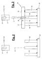
- the beam (3) can according to FIG. 3 with a vertical alignment component from above. Alternatively, it can also be incident from the side or from below, whereby the lower and upper parts (16, 17) are rotated accordingly and have a horizontal or upside-down arrangement.
- the high-energy beam (3) can occur in the joining process normal to the applied workpiece surface and be tracked during track tracing accordingly. He can alternatively come with a deviating from 90 ° Einstrahlwinkel to the workpiece surface and thus obliquely to her.
- the lower part (16) of the composite workpiece (15) has a narrow or thin shape and may for example have the shape of a slender protruding ridge.
- a bridge may be strip-shaped and have a greater continuous length, as in eg FIG. 9 is shown. Alternatively, the bridge can be shorter and have a kind of pinnacle profile.
- a web is also understood to mean a hump or another thin or slender elevation which has a small surface for the joint connection and the attachment surface to the upper part (17).
- the top of the bridge may be flat, curved, or otherwise profiled.
- the lower part (16) may also have a plurality of webs next to each other or in any other assignment, for example, on a support element (20), for example a bottom plate, arranged and welded, for example.
- the upper part (17) of the composite workpiece (15) can have a larger width dimension than the lower part (16) and covers it at least in the joining region, so that the joining region on the lower part (16) is no longer visible from the direction of incidence of the beam.
- the upper part (17) may be plate-shaped and have flat surfaces. It may alternatively have a curved or profiled shape, wherein the contact area is adapted to the provided for the joint connection free end of the web or base (16) and its shape and any contour. In the illustrated embodiment, a plate-shaped upper part (17) is flat on the flat web surface.
- FIGS. 4 and 5 illustrate an embodiment of a composite workpiece (15).
- This may for example be a component (21) of a vehicle, in particular a body part.
- a multi-part interior structure of a vehicle door is shown, which consists of the in FIG. 5 shown items, namely the inner panel with the lower part (16) and the window frame and the diagonal impact beam, both of which form an upper part (17).
- the inner panel is a support member (20) and carries a plurality of upstanding and the lower part (16) forming webs, which may be present individually and in places, but can also circulate like a frame on one or more sides around the window or wall openings.
- the upper parts (17) are concealed or blindly joined in the manner described below.
- the arrangement can also be reversed, wherein the webs (16) are located on the window frame and the diagonal impact beam and the inner panel forms the upper part (17).
- the high-energy beam (3) can be formed in any suitable manner. In the exemplary embodiment shown, it is a light beam, in particular a laser beam. Alternatively it can be an electron beam or another high-energy beam.
- the beam is generated by a beam source (4), for example a laser source, and fed via suitable lines, eg flexible optical fiber cables, to a jet head (5) and emitted by it to the workpiece (15) or its parts (16, 17).
- the beam (3) is focused or focused by the jet head (5). In this case, a plurality of beams (3) can be generated and emitted side by side.
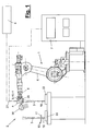
- the jet head (5) is formed in the embodiment shown as a laser head and is guided by a multi-axis manipulator (6), which has a manipulator control (7).
- the manipulator (6) can have multiple rotational and / or translational axes. In the embodiment shown, an articulated arm robot with six or more axes is used.
- the manipulator (6) has a manipulator hand (8), which in turn can have several axes. In the illustrated embodiment, the hand (8) has three orthogonal axes of rotation whose mobility in FIG. 1 is illustrated by arrows. At the output flange of the hand (8) of the jet head (5) is attached.
- the blasting head (5) is held and guided by the manipulator (6) at a greater distance relative to the workpiece parts (16, 17).
- the laser head (5) is designed here as a remote laser and has no physical contact with the workpiece parts (16,17).
- the working distance e.g. is more than 250 mm, preferably about 500 mm or more, the beam (3) can be angularly deflected and moved by this angular movement along a joining path (13) relative to the workpiece parts (16,17).
- the joining web (13) is a welding path or weld which extends along the web-like lower part (16) and runs, for example, in its central region.
- the joining track (13) has front and rear end points (14). It may be to act over the web length continuous joining track (13). Alternatively, an interrupted joining track (13), for example a stitching, is possible.
- the joining track (13) can have a straight course. It can alternatively meander or otherwise have a curved course.
- the blasting head (5) has an optical device (25) in the beam path (27) of the beam (3).
- This can be designed differently. It may include a focusing device, e.g. consists of a lens group with which the outgoing beam (3) is focused.
- the optical device (25) may alternatively or additionally comprise other optical elements, e.g. Mirror, exhibit.
- the said optical elements can be arranged stationary or movable.
- the focusing device may e.g. have curved mirrors. Pivoting mirrors can also be used as a so-called scanner device for angular deflection of the beam (3).
- the optical device (25) may have a fixed focal length. It may alternatively have a variable focal length, which can be varied during the joining process by a suitable adjustment. In this case, an autofocus system can be realized. Focal length changes are e.g. by changes in position of lenses and / or a fiber connector or a coupling point of the beam (3), by using one or more scattering lenses, by changing the position of mirrors, changes in the curvature of mirrors or the like possible.
- the optical device (25) may further comprise means for varying the size of the focus diameter and / or the focal spot of the beam (3) at its impact point have the workpiece surface or at the joint.
- the optical device (25) can eg according to WO 2006/015795 A1 be educated.
- the joining device (1) also has a measuring device (9), which is carried along by the manipulator (6).
- the measuring device is aligned in the emission direction of the beam (3) and has a measuring direction aligned with the beam direction or extending parallel thereto.
- the measuring device (9) in the jet head (5) is integrated or mounted in the area.
- the measuring device (9) is in the in FIG. 1 indicated manner with the manipulator control (7) connected by a wire or wirelessly.
- the measuring device (9) is designed as an optical detection device (10). This can have a different education and function. In the embodiment shown, it is designed as a digital camera and has an image recording device (11), which is designed, for example, as an image sensor with a dense pixel matrix and a high resolution. This can be, for example, a CCD or CMOS chip, which if necessary can also record and measure dynamically. With the image sensor, at least one image of the measuring range can be transmitted via an in FIG. 8 shown viewing window or measuring field are recorded. The one or more images can be stored by the measuring device (9) and output via suitable interfaces in file form or as an expression or the like. In addition, the distance of the lower part (16), for example based on the tool center point of the detection device (10), can be determined by the optical detection device (10).
- the optical detection device (10) also has an image evaluation (12) with which the web-like lower part (16) which appears optically in the viewing window (28) can be detected and measured.
- the image evaluation (12) can capture the regions and reference points of the lower part (16) that are relevant for joining, and measure them according to their size, in particular their width, as well as their shape, position and orientation.
- the detection and measurement takes place via easily recognizable and localisable shape features of the lower part (16), e.g. one or both upper longitudinal edges at the free ends of the web. Alternatively or additionally, other shape features can be detected.
- the viewing window (28) is assigned a suitable coordinate reference system.
- a beam point (29) can be arranged in the viewing window (28) at a central or other suitable location which is aligned with the beam path (27) of the high-energy beam (3).
- a crosshair can be spanned.
- the beam point (29) can form the reference point for determining and measuring the relevant reference points or contours of the lower part (16).
- the position values of the manipulator (6) and the tool center point of the optical detection device (10) can be used to determine absolute position data in space.
- the measurement can be done over the entire length of the joining region on the lower part (16) or in sections or punctually at one or more joints.
- the spatial position and the course of the lower part (16) can be detected.
- the shape and size of the lower part (16) can be detected.
- the width of the joining region for example the web width or sheet thickness there, can be measured.
- possibly parts and web deformations, eg inclinations, indentations, etc. can be detected metrologically.
- clear, easily recognizable shape features in the recorded image are determined with an image evaluation program, with their relative or absolute location coordinates being determined. From the evaluative comparison of relevant shape features, for example parallel longitudinal edges on the web upper side, the width of the intended joining region, eg the local web width, can be determined, for example by calculating the edge distance.
- the image evaluation (12) can also use these measurement data to determine the desired position of the joining path (13) to be followed by the beam (3) on the basis of predetermined criteria, e.g. a middle layer on the web surface, determine.
- the measuring device (9) or possibly the robot controller (7), e.g. the image evaluation (12), for this purpose, can have a suitable computing device with a program together with memory and interfaces for inputting and outputting data.
- the measuring device (9) or possibly the robot controller (7) can have a suitable program part for this purpose.
- This diameter can be adjusted during the joining process, for example via the optical device (25) and its adjusting device.
- the measuring device (9) or possibly the robot controller (7) can be connected for this purpose with this adjusting device for control purposes.
- process monitoring is possible online during beam joining.
- the processing site itself ie the workstation (32) and the local vapor capillary or the plasma can be observed and, for example, monitored. evaluated after color development.
- the joint seam can be viewed and tested for quality.
- the optical detection device (10) is arranged in the beam head (5) and coupled in alignment with the beam path (27) of the high-energy beam (3) by means of a coupling (26).
- the coupling (26) may e.g. a partially transparent, inclined mirror in the beam path (3), which directs the image of the measuring field to the optical detection device (10) and allows the beam (3) to pass.
- the mirror function can also be reversed, wherein the beam (3) is directed to exit the jet head (5).
- the manipulator (6) For measuring the jet head (5) with the measuring device (9) by the manipulator (6) positioned at a predetermined location relative to the lower part (16), wherein a location reference to a coordinate system of the manipulator (6) and the process-relevant tool center point (TCP) of the jet head (5) is produced.
- TCP process-relevant tool center point
- the relevant workpiece data in particular the shape, position and orientation of the lower part (16) can be recorded. Further, it is determined whether the beam spot (29) is located at the intended location or positional relation to the base (16).
- the lower part (16) and / or the to be traced joining path (13) can be searched.
- a predetermined joining path can be programmed and stored in the manipulator control (7).
- the programming being changed accordingly and aligned to be traced joining path (13) after the measurement result and stored.
- a component test can also be carried out for any errors, eg distortions or other deformations, of the lower part (16) in the joint area.
- the measuring device (9) is signal-technically connected to the manipulator control (7) and transmits this to the measurement and evaluation data. Possibly. the image evaluation can also be done in the manipulator control (7).
- the measuring field (28) is smaller than the joining area, then at the lower part (16) according to FIG. 9 several measurements are made, wherein the manipulator (6) the measuring device (9) successively positioned at corresponding measuring points.
- FIG. 2 illustrates how the measuring device (9) is positioned opposite to the lower part (16) to be measured. It can also be seen that a plurality of webs (16) can be arranged together on a support element, for example a bottom plate.
- a pilot beam (31) which, for example, is a visible light beam and is emitted in the beam path (27). Its optically visible impact point on the lower part (16) can be detected metrologically.
- the pilot beam (31) can be, for example, a laser beam with reduced energy or another beam coupled into the beam path (27).
- the joining device (1) furthermore has an illumination device (30) entrained by the manipulator (6), with which the measuring area on the lower part (16) can be illuminated.
- the illumination device (30) is in FIG. 1 schematically shown. It can be designed and arranged as desired and has a plurality of suitable lighting elements, such as headlights or the like. Several light elements can radiate from different directions to the measuring area and illuminate this largely shadowless.
- the illumination device (30) can be attached to the blasting head (5) or to the hand (8) and have a frame-like or cantilever-like frame on which the lighting elements are optionally arranged adjustably and thereby positioned and oriented with a suitable position and orientation to the measuring area.
- the illumination device (30) can be distanced laterally from the blasting head (5) or the hand (8), wherein the lighting elements can also have a mutual distance.
- the measurement of the lower part (16) positioned on a clamping (22) in a predetermined position forms the first process step.
- all intended joining areas are measured completely or in places, with interpolation possibly being made for the formation of the route.
- additional processing e.g. Joining sub-parts (16) with each other, joining other workpiece parts or the like. Be performed.
- the upper part (17) is placed on the lower part (16) and tensioned or fixed in another way.
- This can be done manually or mechanically by a robot or the like, e.g. also from the manipulator (6) with a corresponding tool done.
- the upper part (17) is joined to the lower part (16), the beam (3) being guided along the stored joining track (13) and directed onto the upper part (17).
- the upper part (17) lies with its front side (18) on the lower part (16).
- the beam (3) is directed from the outside to the back (19) of the upper part (17) over the joint, wherein the parts (16) are hidden or blind joined.
- the beam (3) can be focused appropriately.
- at the working or joint (32) in FIG. 3 formed molten bath (33) formed.
- On the right web (16) an already created joint connection is indicated.
- the focus (34) of the high-energy beam (3) is suitably positioned in order to have a correct and optimally optimal energy input at the connection point.
- the focus (34) is e.g. placed at this contact point or connection point between the workpiece parts (16,17) by appropriate adjustment of the optical device (25) with its focusing device.
- the focus (34) can be displaced by changing the working distance by means of a manipulator movement.
- the focus (34) may be slightly above or below this location.
- An energy-rich beam (3) in particular a laser beam, also has, depending on the beam quality, an area in the beam longitudinal direction about the focal point (34), in which the beam diameter is comparatively constant.
- This beam range is referred to as the Raleigh length and may be e.g. between +/- 2 mm and +/- 8 mm. This depends on the beam source (4) used, the optical device (25) and other factors.
- the focal point (34) can be adjusted in its position so that the contact and connection point is in the range of Raleighin.
- the energy input depends on the beam diameter at the contact and joint. From the beam or focus diameter in turn depends on the resulting diameter of the Anbindequeritess.
- the beam diameter in the focus or Raleigh range can the sheet thickness of the lower part or web (16) are adjusted, which also results in an adaptation of the Anbinde- or joining cross-section.
- the diameter of the joining or joining cross section should be equal to or smaller than the web width.
- the focus diameter and the joining or joining cross-section at the T-joint can be very small. With a diameter of the focus (34) or the Raleigh range of e.g. 0.6, the associated diameter of the Anbindequeritess be approximately 0.9 mm.
- the web width can be correspondingly thin and e.g. about 1 mm. With a land width of e.g. 0.8 mm, a diameter of the attachment cross-section of 0.6 mm and a beam diameter of about 0.4 mm are advantageous. For a larger land width of e.g. 1.5 mm, 1.2 mm diameter of the attachment cross section and 0.8 mm beam diameter may be favorable.
- the top (17) may have an equal or greater thickness, e.g. about 0.8 to 1.5 mm.
- the beam (3) can be deflected and guided during the joining exclusively or substantially by an angular movement along the track (13) for the purpose of following the joining track (13).
- This can e.g. through the optical device (25), this being e.g. has a scanner optics with one or more pivotable mirrors or other optical elements.
- the beam deflection can take place by a rotation of the manipulator hand (8) about one or more of its rotational axes.
- the focal length of the optical device (25) is preferably about 500 mm and can also be significantly larger, for example, 1,000 mm, 1,500 mm and more. It can also be smaller and for example 250 mm. Accordingly, the working distance is correspondingly large.
- the beam (3) can cover large paths with its impact point on the upper part (17) through small angular deflections and be guided and controlled very quickly and accurately. Due to the angular deflection, the angle of incidence of the beam (3) on the upper part (17) can change.
- the beam power and / or the path velocity of the beam (3) or the welding speed can be tracked in order to introduce the desired path energy at the upper part (17). This is also possible in conjunction with other beam guiding techniques.
- the focal length and possibly also the focus diameter can be tracked depending on the deflection or angle of incidence via an autofocus system.
- the position of the focus (34) in the beam direction on the workpiece (15, 16, 17) can be adjusted via a focal length adjustment of the optical device (25) and / or by a change of the working distance, e.g. be effected by a movement of the manipulator (6).
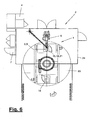
- FIG. 6 shows schematically the formation of a joining station (2), for example a laser welding station.
- the station (2) is surrounded on the outside by a boundary or a protective device, for example a laser cabin (24).
- the joining device (1) is largely arranged in the interior, wherein the laser source (4) can be located outside and is connected via a flexible line with a rotatable gallows with the remote laser head (5) on the manipulator (6).
- the joining station (2) also has a component feed (23), which is designed, for example, as a turntable with two or more clamping points, on which at least the workpiece parts (16) are inserted by a worker. At this point, the finished welded composite workpieces (15) can be removed again and transported away for further processing.
- the Laying the tops (17) after the measurement of the lower parts (16) can be done within the station by the manipulator (6) or other automatic device.
- the component feeder (23) can rotate and the worker places the upper part (17) on and clamps it, while at the other clamping point the next lower part (16) is measured or joined.
- the lower part (16) may have an angled or curved shape, wherein the web width may also change.
- the lower part (16) can have a plurality of webs and e.g. be designed as a U or W profile.
- the lower part (16) may have an open or closed frame shape. It can also be connected to other workpiece parts.
- the beam (3) can also be guided along the joining track (13) in a manner other than by beam deflection. This is e.g. by a driving and / or pivoting movement of the manipulator (6) with its other axes possible.
- the angle of incidence of the beam (3) on the upper part (17) can remain constant or change only slightly.
- the angle of incidence may be aligned in particular perpendicular to the relevant workpiece surface. Alternatively, it may have an inclined position and e.g. be inclined longitudinally or transversely to the web course.
Claims (13)
- Procédé d'assemblage de pièces usinées (15) avec un faisceau (3) riche en énergie guidé par un manipulateur (6) pluriaxial, notamment un faisceau laser ;- une partie supérieure (17) de la pièce usinée (15) étant assemblée à au moins une partie inférieure (16) de type étai ;- la partie inférieure (16) étant d'abord mesurée avec un dispositif de mesure (9) guidé conjointement par le manipulateur (6) et comportant un dispositif de détection (10) optique couplé dans le passage de faisceau (27) du faisceau (3) et la taille de la zone d'assemblage étant calculée ;- la région de mesure située au niveau de la partie inférieure (16) étant éclairée par un dispositif d'éclairage (30) guidé conjointement par le manipulateur (6) et comportant plusieurs éléments d'éclairage éclairant la région de mesure à partir de différentes directions ; et- la voie d'assemblage (13) à suivre avec le faisceau (3) étant orientée et mémorisée en fonction du résultat de mesure ;- la partie supérieure (17) étant ensuite posée puis assemblée à la partie inférieure (16) ;- le faisceau (3) étant guidé le long de la voie d'assemblage (13) mémorisée et orientée sur le côté arrière (19) de la partie supérieure (17) ; et- le faisceau (3) étant émis depuis une tête de faisceau (5) guidée par le manipulateur placé à une certaine distance du lieu de traitement (32), la tête de faisceau (5) comportant un dispositif (25) optique avec une distance focale de 250 mm ou plus, de préférence de 500 mm ou plus.
- Procédé selon la revendication 1, caractérisé en ce que la partie supérieure (17) est placée avec le côté avant (18) sur la partie inférieure (16) et que le faisceau (3) est orienté sur le côté arrière (19) de la partie supérieure (17).
- Procédé selon la revendication 1 ou 2, caractérisé en ce que la partie inférieure (16) est mesurée en fonction de sa forme, de sa position et de son orientation, la position théorique de la voie d'assemblage (13) étant calculée à partir du résultat de mesure.
- Procédé selon la revendication 1, 2 ou 3, caractérisé en ce que lors de la mesure, on recherche la partie inférieure (16) et/ou la position théorique de la voie d'assemblage (13).
- Procédé selon la revendication 1, 2 ou 3, caractérisé en ce que le résultat de mesure est comparé à des données préprogrammées de la partie inférieure (16) et/ou de la voie d'assemblage (13) et qu'en cas d'écarts, les données préprogrammées sont corrigées.
- Procédé selon l'une quelconque des revendications précédentes, caractérisé en ce lors de la mesure de la zone d'assemblage, la taille de foyer adaptée est déterminée et réglée lors du processus d'assemblage.
- Procédé selon l'une quelconque des revendications précédentes, caractérisé en ce que la partie inférieure (16) est détectée en fonction de l'image et mesurée par le dispositif de mesure (9) à l'aide d'un dispositif de détection (10) optique couplé dans le passage de faisceau (27) du faisceau (3), sachant qu'à partir de l'image détectée, on calcule la forme, la position et l'orientation de la partie inférieure (16) à l'aide d'une analyse d'image (12) avant de transmettre ces éléments à l'élément de commande de manipulateur (11).
- Procédé selon l'une quelconque des revendications précédentes, caractérisé en ce que le faisceau (3) est articulé pour le suivi de voie lors de l'assemblage par un dispositif optique (25), notamment un lecteur optique ou par une rotation d'une main de manipulateur (8) autour d'un ou de plusieurs axes.
- Dispositif d'assemblage servant à mettre en oeuvre le procédé selon l'une quelconque des revendications 1 à 8, caractérisé en ce que le dispositif d'assemblage (1) comporte une source de faisceau (4) et au moins un manipulateur pluriaxial (6) avec une tête de faisceau (5) pour l'émission d'au moins un faisceau (3) riche en énergie, notamment d'un faisceau laser, à une certaine distance du lieu de traitement (32) et avec un dispositif de mesure (9) guidé conjointement relié à l'élément de commande de manipulateur (7), le dispositif de mesure (9) comportant un dispositif de détection (10) optique couplé dans le passage de faisceau (27) et un dispositif d'éclairage (30) étant disposé au niveau du manipulateur (6) pour éclairer la région de mesure, ledit dispositif comportant plusieurs éléments d'éclairage éclairant la région de mesure à partir de différentes directions et la tête de faisceau (5) comportant un dispositif optique (25) avec une distance focale de 250 mm ou plus, de préférence de 500 mm ou plus.
- Dispositif d'assemblage selon la revendication 9, caractérisé en ce que le dispositif de détection (10) optique comporte un dispositif de prise d'image (11) et une analyse d'image (12).
- Dispositif d'assemblage selon la revendication 9 ou 10, caractérisé en ce que l'analyse d'image (12) comporte une partie de programme pour déterminer la taille, notamment la largeur, de la zone d'assemblage prise et une partie de programme pour déterminer la taille de foyer adaptée au niveau de la zone d'assemblage.
- Dispositif d'assemblage selon l'une quelconque des revendications 9 à 11, caractérisé en ce que la source de faisceau (4) émet à des fins de mesure au moins un faisceau laser (3) riche en énergie et le cas échéant un faisceau pilote (31) plus faible.
- Dispositif d'assemblage selon l'une quelconque des revendications 9 à 12, caractérisé en ce que le dispositif optique (25) présente une distance focale variable et un dispositif de réglage servant à faire varier la distance focale, ledit dispositif étant relié au dispositif de mesure (9).
Priority Applications (1)
| Application Number | Priority Date | Filing Date | Title |
|---|---|---|---|
| PL08863544T PL2242623T3 (pl) | 2007-12-20 | 2008-12-15 | Sposób łączenia i urządzenie do łączenia |
Applications Claiming Priority (2)
| Application Number | Priority Date | Filing Date | Title |
|---|---|---|---|
| DE102007062535A DE102007062535A1 (de) | 2007-12-20 | 2007-12-20 | Verfahren und Einrichtung zum Fügen |
| PCT/EP2008/010640 WO2009080233A1 (fr) | 2007-12-20 | 2008-12-15 | Procédé et dispositif d'assemblage |
Publications (2)
| Publication Number | Publication Date |
|---|---|
| EP2242623A1 EP2242623A1 (fr) | 2010-10-27 |
| EP2242623B1 true EP2242623B1 (fr) | 2015-08-26 |
Family
ID=40473590
Family Applications (1)
| Application Number | Title | Priority Date | Filing Date |
|---|---|---|---|
| EP08863544.6A Active EP2242623B1 (fr) | 2007-12-20 | 2008-12-15 | Procédé et dispositif d'assemblage |
Country Status (4)
| Country | Link |
|---|---|
| EP (1) | EP2242623B1 (fr) |
| DE (1) | DE102007062535A1 (fr) |
| PL (1) | PL2242623T3 (fr) |
| WO (1) | WO2009080233A1 (fr) |
Families Citing this family (11)
| Publication number | Priority date | Publication date | Assignee | Title |
|---|---|---|---|---|
| DE202011000456U1 (de) | 2011-02-28 | 2012-05-31 | Kuka Systems Gmbh | Fügeeinrichtung |
| DE102011014463A1 (de) * | 2011-03-19 | 2012-09-20 | Audi Ag | Rollfalzverfahren zum randseitigen Verbinden von Blechen, insbesondere von Karosserieblechen |
| DE102012021658A1 (de) * | 2012-05-03 | 2013-11-07 | Dürr Systems GmbH | Rotorblattherstellvorrichtung und zugehöriges Verfahren |
| DE102012012298A1 (de) * | 2012-06-20 | 2013-12-24 | Dürr Systems GmbH | Klebeverfahren und entsprechende Klebevorrichtung |
| DE102012018003A1 (de) | 2012-09-12 | 2014-03-13 | Volkswagen Aktiengesellschaft | Beschneiden eines Formteils mittels eines Energiestrahls |
| ES2556564T3 (es) | 2013-05-22 | 2016-01-18 | Fft Produktionssysteme Gmbh & Co. Kg | Ensamblaje de una pieza de trabajo con una soldadura de ensamblaje escondida |
| DE102015115183A1 (de) * | 2015-09-09 | 2017-03-09 | BIAS - Bremer Institut für angewandte Strahltechnik GmbH | Verfahren und eine Vorrichtung zum Herstellen einer Fügeverbindung |
| DE102017219184B4 (de) | 2017-10-26 | 2023-02-02 | Trumpf Laser- Und Systemtechnik Gmbh | Bestrahlungseinrichtung und Bearbeitungsmaschine zum Bestrahlen eines ebenen Bearbeitungsfeldes |
| CN109732604B (zh) * | 2019-01-21 | 2020-06-19 | 成都宇俊盛科技有限公司 | 一种通过电眼进行机械手移动对位的方法 |
| CN110407010B (zh) * | 2019-06-25 | 2021-03-19 | 安吉八塔机器人有限公司 | 一种适用于弹性材料的搬运与纠偏系统及其方法 |
| DE102021124053A1 (de) | 2021-09-17 | 2023-03-23 | Bayerische Motoren Werke Aktiengesellschaft | Verfahren zum Bereitstellen von Informationen für eine Robotereinrichtung sowie elektronische Recheneinrichtung |
Family Cites Families (6)
| Publication number | Priority date | Publication date | Assignee | Title |
|---|---|---|---|---|
| DE4402345C1 (de) * | 1994-01-27 | 1995-05-24 | Fraunhofer Ges Forschung | Vorrichtung zum Verschweißen eines Gurts und eines Stegs, insbesondere zu einem T- oder I-Stoß, mit Hochenergiestrahlung |
| DE19913756A1 (de) * | 1999-03-26 | 2000-09-28 | Audi Ag | Vorrichtung zum Teachen eines programmgesteuerten Roboters |
| DE10335501B4 (de) * | 2002-07-31 | 2005-01-27 | Kuka Schweissanlagen Gmbh | Verfahren und Vorrichtung zum Schweißen oder Schneiden mit Laserstrahl |
| DE10326377B3 (de) * | 2003-06-12 | 2004-12-16 | Thyssenkrupp Drauz Gmbh | Verfahren zum Laserschweißen eines Blechteils an einen Querschnitt eines Profils mittels verdeckter Schweißnähte und zu deren automatischer zerstörungsfreien Prüfung |
| DE102004038310A1 (de) * | 2004-08-05 | 2006-02-23 | Kuka Schweissanlagen Gmbh | Lasereinrichtung und Betriebsverfahren |
| DE202006005916U1 (de) * | 2006-04-10 | 2007-08-16 | Kuka Schweissanlagen Gmbh | Überwachungseinrichtung |
-
2007
- 2007-12-20 DE DE102007062535A patent/DE102007062535A1/de not_active Withdrawn
-
2008
- 2008-12-15 EP EP08863544.6A patent/EP2242623B1/fr active Active
- 2008-12-15 PL PL08863544T patent/PL2242623T3/pl unknown
- 2008-12-15 WO PCT/EP2008/010640 patent/WO2009080233A1/fr active Application Filing
Also Published As
| Publication number | Publication date |
|---|---|
| PL2242623T3 (pl) | 2016-01-29 |
| WO2009080233A1 (fr) | 2009-07-02 |
| EP2242623A1 (fr) | 2010-10-27 |
| DE102007062535A1 (de) | 2009-06-25 |
Similar Documents
| Publication | Publication Date | Title |
|---|---|---|
| EP2242623B1 (fr) | Procédé et dispositif d'assemblage | |
| DE10335501B4 (de) | Verfahren und Vorrichtung zum Schweißen oder Schneiden mit Laserstrahl | |
| DE102006018558B4 (de) | Verfahren zum automatischen Aufbringen oder Erzeugen und Überwachen einer auf einem Substrat aufgebrachten Struktur mit Ermittlung von geometrischen Abmessungen | |
| DE102005022095B4 (de) | Verfahren und Vorrichtung zur Bestimmung einer lateralen Relativbewegung zwischen einem Bearbeitungskopf und einem Werkstück | |
| DE102011104550B4 (de) | Optische Messvorrichtung zur Überwachung einer Fügenaht, Fügekopf und Laserschweißkopf mit der selben | |
| EP2131145B1 (fr) | Dispositif de surveillance optique | |
| WO2011110357A1 (fr) | Tête d'usinage au laser et procédé pour l'usinage d'une pièce au moyen d'un faisceau laser | |
| DE102012212278B4 (de) | Anordnung zum Erzeugen von Bohrungen oder Schweißnähten | |
| DE202006005916U1 (de) | Überwachungseinrichtung | |
| DE102016014564A1 (de) | Messvorrichtung zum Überwachen eines Bearbeitungsprozesses unter Verwendung von an unterschiedlichen Messpositionen erfassten Messinformationen | |
| WO2019120557A1 (fr) | Dispositif optique d'application ou de production et de surveillance automatiques d'une structure déposée sur un substrat avec détermination de dimensions géométriques et procédé correspondant | |
| WO2019158580A1 (fr) | Système d'ajustement d'un écoulement de poudre par rapport à l'axe longitudinal central d'un rayon d'énergie | |
| DE102017010055A1 (de) | Laserstrahlschweißen von geometrischen Figuren mit OCT-Nahtführung | |
| DE102006006204B4 (de) | Anordnung zur optischen Kontrolle des Arbeitsergebnisses eines Werkzeugs und/oder zur Führung eines Werkeugs | |
| DE202010008808U1 (de) | Bearbeitungswerkzeug | |
| EP3710199B1 (fr) | Dispositif et procédé pour déterminer la position et/ou l'orientation d'une pièce | |
| DE102007031835B4 (de) | Optische Führung und online Kontrolle an einem Werkzeug | |
| DE102008010965B4 (de) | Roboter-Bahnführung | |
| DE102016005592B4 (de) | Verfahren zum Laserstrahlfügen und Vorrichtung mit einer Laserstrahlenquelle zum Laserstrahlfügen | |
| AT522419B1 (de) | Messvorrichtung zur Bestimmung des Biegewinkels | |
| DE102017114518B4 (de) | Laserstrahlschneiden | |
| DE202023106060U1 (de) | Eine Schweißvorrichtung | |
| DE102021134245A1 (de) | Koordinatenmessgerät, Verfahren zur Steuerung eines Koordinatenmessgerätes und Computerprogrammprodukt | |
| EP3760357A1 (fr) | Système et procédé de détermination d'une vitesse de soudage ou de brasage | |
| EP1529592A1 (fr) | Dispositif et arrangement pour aligner un faisceau laser ainsi qu'un procédé d'apprentissage utilisant l'arrangement |
Legal Events
| Date | Code | Title | Description |
|---|---|---|---|
| PUAI | Public reference made under article 153(3) epc to a published international application that has entered the european phase |
Free format text: ORIGINAL CODE: 0009012 |
|
| 17P | Request for examination filed |
Effective date: 20100715 |
|
| AK | Designated contracting states |
Kind code of ref document: A1 Designated state(s): AT BE BG CH CY CZ DE DK EE ES FI FR GB GR HR HU IE IS IT LI LT LU LV MC MT NL NO PL PT RO SE SI SK TR |
|
| AX | Request for extension of the european patent |
Extension state: AL BA MK RS |
|
| RIN1 | Information on inventor provided before grant (corrected) |
Inventor name: EBERL, MARTIN Inventor name: HERRMANN, MANFRED Inventor name: ENGLHARD, ANTON |
|
| 17Q | First examination report despatched |
Effective date: 20110113 |
|
| DAX | Request for extension of the european patent (deleted) | ||
| GRAP | Despatch of communication of intention to grant a patent |
Free format text: ORIGINAL CODE: EPIDOSNIGR1 |
|
| INTG | Intention to grant announced |
Effective date: 20150521 |
|
| GRAS | Grant fee paid |
Free format text: ORIGINAL CODE: EPIDOSNIGR3 |
|
| GRAA | (expected) grant |
Free format text: ORIGINAL CODE: 0009210 |
|
| AK | Designated contracting states |
Kind code of ref document: B1 Designated state(s): AT BE BG CH CY CZ DE DK EE ES FI FR GB GR HR HU IE IS IT LI LT LU LV MC MT NL NO PL PT RO SE SI SK TR |
|
| REG | Reference to a national code |
Ref country code: GB Ref legal event code: FG4D Free format text: NOT ENGLISH |
|
| REG | Reference to a national code |
Ref country code: CH Ref legal event code: EP |
|
| REG | Reference to a national code |
Ref country code: AT Ref legal event code: REF Ref document number: 744892 Country of ref document: AT Kind code of ref document: T Effective date: 20150915 |
|
| REG | Reference to a national code |
Ref country code: IE Ref legal event code: FG4D Free format text: LANGUAGE OF EP DOCUMENT: GERMAN |
|
| REG | Reference to a national code |
Ref country code: DE Ref legal event code: R096 Ref document number: 502008013324 Country of ref document: DE |
|
| REG | Reference to a national code |
Ref country code: FR Ref legal event code: PLFP Year of fee payment: 8 |
|
| REG | Reference to a national code |
Ref country code: NL Ref legal event code: FP |
|
| REG | Reference to a national code |
Ref country code: LT Ref legal event code: MG4D |
|
| PG25 | Lapsed in a contracting state [announced via postgrant information from national office to epo] |
Ref country code: GR Free format text: LAPSE BECAUSE OF FAILURE TO SUBMIT A TRANSLATION OF THE DESCRIPTION OR TO PAY THE FEE WITHIN THE PRESCRIBED TIME-LIMIT Effective date: 20151127 Ref country code: NO Free format text: LAPSE BECAUSE OF FAILURE TO SUBMIT A TRANSLATION OF THE DESCRIPTION OR TO PAY THE FEE WITHIN THE PRESCRIBED TIME-LIMIT Effective date: 20151126 Ref country code: FI Free format text: LAPSE BECAUSE OF FAILURE TO SUBMIT A TRANSLATION OF THE DESCRIPTION OR TO PAY THE FEE WITHIN THE PRESCRIBED TIME-LIMIT Effective date: 20150826 Ref country code: LT Free format text: LAPSE BECAUSE OF FAILURE TO SUBMIT A TRANSLATION OF THE DESCRIPTION OR TO PAY THE FEE WITHIN THE PRESCRIBED TIME-LIMIT Effective date: 20150826 Ref country code: LV Free format text: LAPSE BECAUSE OF FAILURE TO SUBMIT A TRANSLATION OF THE DESCRIPTION OR TO PAY THE FEE WITHIN THE PRESCRIBED TIME-LIMIT Effective date: 20150826 |
|
| PG25 | Lapsed in a contracting state [announced via postgrant information from national office to epo] |
Ref country code: ES Free format text: LAPSE BECAUSE OF FAILURE TO SUBMIT A TRANSLATION OF THE DESCRIPTION OR TO PAY THE FEE WITHIN THE PRESCRIBED TIME-LIMIT Effective date: 20150826 Ref country code: HR Free format text: LAPSE BECAUSE OF FAILURE TO SUBMIT A TRANSLATION OF THE DESCRIPTION OR TO PAY THE FEE WITHIN THE PRESCRIBED TIME-LIMIT Effective date: 20150826 Ref country code: IS Free format text: LAPSE BECAUSE OF FAILURE TO SUBMIT A TRANSLATION OF THE DESCRIPTION OR TO PAY THE FEE WITHIN THE PRESCRIBED TIME-LIMIT Effective date: 20151226 Ref country code: SE Free format text: LAPSE BECAUSE OF FAILURE TO SUBMIT A TRANSLATION OF THE DESCRIPTION OR TO PAY THE FEE WITHIN THE PRESCRIBED TIME-LIMIT Effective date: 20150826 Ref country code: PT Free format text: LAPSE BECAUSE OF FAILURE TO SUBMIT A TRANSLATION OF THE DESCRIPTION OR TO PAY THE FEE WITHIN THE PRESCRIBED TIME-LIMIT Effective date: 20151228 |
|
| REG | Reference to a national code |
Ref country code: DE Ref legal event code: R082 Ref document number: 502008013324 Country of ref document: DE Representative=s name: KILBURN & STRODE LLP, NL Ref country code: DE Ref legal event code: R082 Ref document number: 502008013324 Country of ref document: DE Representative=s name: KILBURN & STRODE LLP, GB Ref country code: DE Ref legal event code: R081 Ref document number: 502008013324 Country of ref document: DE Owner name: KUKA INDUSTRIES GMBH, DE Free format text: FORMER OWNER: KUKA SYSTEMS GMBH, 86165 AUGSBURG, DE |
|
| PG25 | Lapsed in a contracting state [announced via postgrant information from national office to epo] |
Ref country code: CZ Free format text: LAPSE BECAUSE OF FAILURE TO SUBMIT A TRANSLATION OF THE DESCRIPTION OR TO PAY THE FEE WITHIN THE PRESCRIBED TIME-LIMIT Effective date: 20150826 Ref country code: DK Free format text: LAPSE BECAUSE OF FAILURE TO SUBMIT A TRANSLATION OF THE DESCRIPTION OR TO PAY THE FEE WITHIN THE PRESCRIBED TIME-LIMIT Effective date: 20150826 Ref country code: IT Free format text: LAPSE BECAUSE OF FAILURE TO SUBMIT A TRANSLATION OF THE DESCRIPTION OR TO PAY THE FEE WITHIN THE PRESCRIBED TIME-LIMIT Effective date: 20150826 Ref country code: SK Free format text: LAPSE BECAUSE OF FAILURE TO SUBMIT A TRANSLATION OF THE DESCRIPTION OR TO PAY THE FEE WITHIN THE PRESCRIBED TIME-LIMIT Effective date: 20150826 Ref country code: EE Free format text: LAPSE BECAUSE OF FAILURE TO SUBMIT A TRANSLATION OF THE DESCRIPTION OR TO PAY THE FEE WITHIN THE PRESCRIBED TIME-LIMIT Effective date: 20150826 |
|
| REG | Reference to a national code |
Ref country code: DE Ref legal event code: R097 Ref document number: 502008013324 Country of ref document: DE |
|
| PG25 | Lapsed in a contracting state [announced via postgrant information from national office to epo] |
Ref country code: RO Free format text: LAPSE BECAUSE OF FAILURE TO SUBMIT A TRANSLATION OF THE DESCRIPTION OR TO PAY THE FEE WITHIN THE PRESCRIBED TIME-LIMIT Effective date: 20150826 Ref country code: BE Free format text: LAPSE BECAUSE OF NON-PAYMENT OF DUE FEES Effective date: 20151231 |
|
| PLBE | No opposition filed within time limit |
Free format text: ORIGINAL CODE: 0009261 |
|
| STAA | Information on the status of an ep patent application or granted ep patent |
Free format text: STATUS: NO OPPOSITION FILED WITHIN TIME LIMIT |
|
| PG25 | Lapsed in a contracting state [announced via postgrant information from national office to epo] |
Ref country code: LU Free format text: LAPSE BECAUSE OF FAILURE TO SUBMIT A TRANSLATION OF THE DESCRIPTION OR TO PAY THE FEE WITHIN THE PRESCRIBED TIME-LIMIT Effective date: 20151215 Ref country code: MC Free format text: LAPSE BECAUSE OF FAILURE TO SUBMIT A TRANSLATION OF THE DESCRIPTION OR TO PAY THE FEE WITHIN THE PRESCRIBED TIME-LIMIT Effective date: 20150826 |
|
| REG | Reference to a national code |
Ref country code: CH Ref legal event code: PL |
|
| 26N | No opposition filed |
Effective date: 20160530 |
|
| PG25 | Lapsed in a contracting state [announced via postgrant information from national office to epo] |
Ref country code: SI Free format text: LAPSE BECAUSE OF FAILURE TO SUBMIT A TRANSLATION OF THE DESCRIPTION OR TO PAY THE FEE WITHIN THE PRESCRIBED TIME-LIMIT Effective date: 20150826 |
|
| REG | Reference to a national code |
Ref country code: IE Ref legal event code: MM4A |
|
| PG25 | Lapsed in a contracting state [announced via postgrant information from national office to epo] |
Ref country code: LI Free format text: LAPSE BECAUSE OF NON-PAYMENT OF DUE FEES Effective date: 20151231 Ref country code: IE Free format text: LAPSE BECAUSE OF NON-PAYMENT OF DUE FEES Effective date: 20151215 Ref country code: CH Free format text: LAPSE BECAUSE OF NON-PAYMENT OF DUE FEES Effective date: 20151231 |
|
| REG | Reference to a national code |
Ref country code: FR Ref legal event code: PLFP Year of fee payment: 9 |
|
| REG | Reference to a national code |
Ref country code: AT Ref legal event code: MM01 Ref document number: 744892 Country of ref document: AT Kind code of ref document: T Effective date: 20151215 |
|
| PG25 | Lapsed in a contracting state [announced via postgrant information from national office to epo] |
Ref country code: BG Free format text: LAPSE BECAUSE OF FAILURE TO SUBMIT A TRANSLATION OF THE DESCRIPTION OR TO PAY THE FEE WITHIN THE PRESCRIBED TIME-LIMIT Effective date: 20150826 Ref country code: HU Free format text: LAPSE BECAUSE OF FAILURE TO SUBMIT A TRANSLATION OF THE DESCRIPTION OR TO PAY THE FEE WITHIN THE PRESCRIBED TIME-LIMIT; INVALID AB INITIO Effective date: 20081215 Ref country code: AT Free format text: LAPSE BECAUSE OF NON-PAYMENT OF DUE FEES Effective date: 20151215 |
|
| PG25 | Lapsed in a contracting state [announced via postgrant information from national office to epo] |
Ref country code: CY Free format text: LAPSE BECAUSE OF FAILURE TO SUBMIT A TRANSLATION OF THE DESCRIPTION OR TO PAY THE FEE WITHIN THE PRESCRIBED TIME-LIMIT Effective date: 20150826 |
|
| PG25 | Lapsed in a contracting state [announced via postgrant information from national office to epo] |
Ref country code: TR Free format text: LAPSE BECAUSE OF FAILURE TO SUBMIT A TRANSLATION OF THE DESCRIPTION OR TO PAY THE FEE WITHIN THE PRESCRIBED TIME-LIMIT Effective date: 20150826 Ref country code: MT Free format text: LAPSE BECAUSE OF FAILURE TO SUBMIT A TRANSLATION OF THE DESCRIPTION OR TO PAY THE FEE WITHIN THE PRESCRIBED TIME-LIMIT Effective date: 20150826 |
|
| REG | Reference to a national code |
Ref country code: FR Ref legal event code: PLFP Year of fee payment: 10 |
|
| REG | Reference to a national code |
Ref country code: DE Ref legal event code: R082 Ref document number: 502008013324 Country of ref document: DE Representative=s name: KILBURN & STRODE LLP, NL |
|
| P01 | Opt-out of the competence of the unified patent court (upc) registered |
Effective date: 20230528 |
|
| PGFP | Annual fee paid to national office [announced via postgrant information from national office to epo] |
Ref country code: PL Payment date: 20230928 Year of fee payment: 16 Ref country code: NL Payment date: 20231016 Year of fee payment: 16 |
|
| PGFP | Annual fee paid to national office [announced via postgrant information from national office to epo] |
Ref country code: GB Payment date: 20231026 Year of fee payment: 16 |
|
| PGFP | Annual fee paid to national office [announced via postgrant information from national office to epo] |
Ref country code: FR Payment date: 20231009 Year of fee payment: 16 Ref country code: DE Payment date: 20231017 Year of fee payment: 16 |