EP2242623B1 - Method and device for joining - Google Patents
Method and device for joining Download PDFInfo
- Publication number
- EP2242623B1 EP2242623B1 EP08863544.6A EP08863544A EP2242623B1 EP 2242623 B1 EP2242623 B1 EP 2242623B1 EP 08863544 A EP08863544 A EP 08863544A EP 2242623 B1 EP2242623 B1 EP 2242623B1
- Authority
- EP
- European Patent Office
- Prior art keywords
- joining
- manipulator
- web
- measurement
- optical
- Prior art date
- Legal status (The legal status is an assumption and is not a legal conclusion. Google has not performed a legal analysis and makes no representation as to the accuracy of the status listed.)
- Active
Links
- 238000005304 joining Methods 0.000 title claims description 92
- 238000000034 method Methods 0.000 title claims description 38
- 230000003287 optical effect Effects 0.000 claims description 37
- 238000005259 measurement Methods 0.000 claims description 34
- 230000008569 process Effects 0.000 claims description 11
- 238000003384 imaging method Methods 0.000 claims 1
- 238000003466 welding Methods 0.000 description 20
- 238000001514 detection method Methods 0.000 description 13
- 238000011156 evaluation Methods 0.000 description 8
- 238000005422 blasting Methods 0.000 description 6
- 239000002131 composite material Substances 0.000 description 6
- 238000005286 illumination Methods 0.000 description 6
- 230000008859 change Effects 0.000 description 5
- 238000012545 processing Methods 0.000 description 5
- 230000008878 coupling Effects 0.000 description 4
- 238000010168 coupling process Methods 0.000 description 4
- 238000005859 coupling reaction Methods 0.000 description 4
- 238000010191 image analysis Methods 0.000 description 3
- 230000008901 benefit Effects 0.000 description 2
- 230000015572 biosynthetic process Effects 0.000 description 2
- 238000000576 coating method Methods 0.000 description 2
- 238000013461 design Methods 0.000 description 2
- 238000010894 electron beam technology Methods 0.000 description 2
- 230000002349 favourable effect Effects 0.000 description 2
- 230000006870 function Effects 0.000 description 2
- 239000011159 matrix material Substances 0.000 description 2
- 239000002184 metal Substances 0.000 description 2
- 229910052751 metal Inorganic materials 0.000 description 2
- 238000001454 recorded image Methods 0.000 description 2
- 101100165186 Caenorhabditis elegans bath-34 gene Proteins 0.000 description 1
- 229910052770 Uranium Inorganic materials 0.000 description 1
- HCHKCACWOHOZIP-UHFFFAOYSA-N Zinc Chemical compound [Zn] HCHKCACWOHOZIP-UHFFFAOYSA-N 0.000 description 1
- 230000006978 adaptation Effects 0.000 description 1
- 238000004026 adhesive bonding Methods 0.000 description 1
- 238000005260 corrosion Methods 0.000 description 1
- 230000007797 corrosion Effects 0.000 description 1
- 238000011161 development Methods 0.000 description 1
- 239000000835 fiber Substances 0.000 description 1
- 238000007373 indentation Methods 0.000 description 1
- 230000013011 mating Effects 0.000 description 1
- 238000002844 melting Methods 0.000 description 1
- 230000008018 melting Effects 0.000 description 1
- 238000012986 modification Methods 0.000 description 1
- 230000004048 modification Effects 0.000 description 1
- 238000012544 monitoring process Methods 0.000 description 1
- 238000010943 off-gassing Methods 0.000 description 1
- 239000013307 optical fiber Substances 0.000 description 1
- 238000005192 partition Methods 0.000 description 1
- 230000001681 protective effect Effects 0.000 description 1
- 230000005855 radiation Effects 0.000 description 1
- 238000005476 soldering Methods 0.000 description 1
- 238000012360 testing method Methods 0.000 description 1
- 229910052725 zinc Inorganic materials 0.000 description 1
- 239000011701 zinc Substances 0.000 description 1
Images


Classifications
-
- B—PERFORMING OPERATIONS; TRANSPORTING
- B25—HAND TOOLS; PORTABLE POWER-DRIVEN TOOLS; MANIPULATORS
- B25J—MANIPULATORS; CHAMBERS PROVIDED WITH MANIPULATION DEVICES
- B25J9/00—Programme-controlled manipulators
- B25J9/16—Programme controls
- B25J9/1679—Programme controls characterised by the tasks executed
- B25J9/1684—Tracking a line or surface by means of sensors
-
- B—PERFORMING OPERATIONS; TRANSPORTING
- B23—MACHINE TOOLS; METAL-WORKING NOT OTHERWISE PROVIDED FOR
- B23K—SOLDERING OR UNSOLDERING; WELDING; CLADDING OR PLATING BY SOLDERING OR WELDING; CUTTING BY APPLYING HEAT LOCALLY, e.g. FLAME CUTTING; WORKING BY LASER BEAM
- B23K26/00—Working by laser beam, e.g. welding, cutting or boring
- B23K26/02—Positioning or observing the workpiece, e.g. with respect to the point of impact; Aligning, aiming or focusing the laser beam
- B23K26/04—Automatically aligning, aiming or focusing the laser beam, e.g. using the back-scattered light
- B23K26/042—Automatically aligning the laser beam
-
- B—PERFORMING OPERATIONS; TRANSPORTING
- B23—MACHINE TOOLS; METAL-WORKING NOT OTHERWISE PROVIDED FOR
- B23K—SOLDERING OR UNSOLDERING; WELDING; CLADDING OR PLATING BY SOLDERING OR WELDING; CUTTING BY APPLYING HEAT LOCALLY, e.g. FLAME CUTTING; WORKING BY LASER BEAM
- B23K26/00—Working by laser beam, e.g. welding, cutting or boring
- B23K26/08—Devices involving relative movement between laser beam and workpiece
- B23K26/0869—Devices involving movement of the laser head in at least one axial direction
- B23K26/0876—Devices involving movement of the laser head in at least one axial direction in at least two axial directions
- B23K26/0884—Devices involving movement of the laser head in at least one axial direction in at least two axial directions in at least in three axial directions, e.g. manipulators, robots
-
- B—PERFORMING OPERATIONS; TRANSPORTING
- B25—HAND TOOLS; PORTABLE POWER-DRIVEN TOOLS; MANIPULATORS
- B25J—MANIPULATORS; CHAMBERS PROVIDED WITH MANIPULATION DEVICES
- B25J9/00—Programme-controlled manipulators
- B25J9/16—Programme controls
- B25J9/1656—Programme controls characterised by programming, planning systems for manipulators
- B25J9/1664—Programme controls characterised by programming, planning systems for manipulators characterised by motion, path, trajectory planning
-
- B—PERFORMING OPERATIONS; TRANSPORTING
- B25—HAND TOOLS; PORTABLE POWER-DRIVEN TOOLS; MANIPULATORS
- B25J—MANIPULATORS; CHAMBERS PROVIDED WITH MANIPULATION DEVICES
- B25J9/00—Programme-controlled manipulators
- B25J9/16—Programme controls
- B25J9/1694—Programme controls characterised by use of sensors other than normal servo-feedback from position, speed or acceleration sensors, perception control, multi-sensor controlled systems, sensor fusion
- B25J9/1697—Vision controlled systems
-
- B—PERFORMING OPERATIONS; TRANSPORTING
- B23—MACHINE TOOLS; METAL-WORKING NOT OTHERWISE PROVIDED FOR
- B23K—SOLDERING OR UNSOLDERING; WELDING; CLADDING OR PLATING BY SOLDERING OR WELDING; CUTTING BY APPLYING HEAT LOCALLY, e.g. FLAME CUTTING; WORKING BY LASER BEAM
- B23K2101/00—Articles made by soldering, welding or cutting
- B23K2101/006—Vehicles
-
- G—PHYSICS
- G05—CONTROLLING; REGULATING
- G05B—CONTROL OR REGULATING SYSTEMS IN GENERAL; FUNCTIONAL ELEMENTS OF SUCH SYSTEMS; MONITORING OR TESTING ARRANGEMENTS FOR SUCH SYSTEMS OR ELEMENTS
- G05B2219/00—Program-control systems
- G05B2219/30—Nc systems
- G05B2219/36—Nc in input of data, input key till input tape
- G05B2219/36414—Compare image detected path with stored reference, difference corrects position
-
- G—PHYSICS
- G05—CONTROLLING; REGULATING
- G05B—CONTROL OR REGULATING SYSTEMS IN GENERAL; FUNCTIONAL ELEMENTS OF SUCH SYSTEMS; MONITORING OR TESTING ARRANGEMENTS FOR SUCH SYSTEMS OR ELEMENTS
- G05B2219/00—Program-control systems
- G05B2219/30—Nc systems
- G05B2219/40—Robotics, robotics mapping to robotics vision
- G05B2219/40425—Sensing, vision based motion planning
-
- G—PHYSICS
- G05—CONTROLLING; REGULATING
- G05B—CONTROL OR REGULATING SYSTEMS IN GENERAL; FUNCTIONAL ELEMENTS OF SUCH SYSTEMS; MONITORING OR TESTING ARRANGEMENTS FOR SUCH SYSTEMS OR ELEMENTS
- G05B2219/00—Program-control systems
- G05B2219/30—Nc systems
- G05B2219/45—Nc applications
- G05B2219/45104—Lasrobot, welding robot
-
- G—PHYSICS
- G05—CONTROLLING; REGULATING
- G05B—CONTROL OR REGULATING SYSTEMS IN GENERAL; FUNCTIONAL ELEMENTS OF SUCH SYSTEMS; MONITORING OR TESTING ARRANGEMENTS FOR SUCH SYSTEMS OR ELEMENTS
- G05B2219/00—Program-control systems
- G05B2219/30—Nc systems
- G05B2219/45—Nc applications
- G05B2219/45138—Laser welding
-
- G—PHYSICS
- G05—CONTROLLING; REGULATING
- G05B—CONTROL OR REGULATING SYSTEMS IN GENERAL; FUNCTIONAL ELEMENTS OF SUCH SYSTEMS; MONITORING OR TESTING ARRANGEMENTS FOR SUCH SYSTEMS OR ELEMENTS
- G05B2219/00—Program-control systems
- G05B2219/30—Nc systems
- G05B2219/49—Nc machine tool, till multiple
- G05B2219/49386—Automatic seam, weld line, finding
Definitions
- the invention relates to a method and a device for joining workpieces with the features in the preamble of the method and device main claim.
- a method for laser welding a sheet metal part to a cross section of a profile by means of concealed welding seams is known.
- the cross-section of the thin-walled profile is detected by a sensor system designed as an image processing system, the image processing system calculating the welding path therefrom.
- the values of the web are input to the control of a welding robot.
- the sheet metal part in the form of a bulkhead plate is made to measure the end face of the thin-walled profile by a robot.
- the welding robot moves the tool head of the laser along the welding path and thus welds the partition plate with the thin-walled profile by means of a hidden T-seam.
- the DE 103 35 501 A1 discloses a method and apparatus for welding workpieces along a workpiece edge with a laser head moved by a robot that focuses a laser beam onto the process location.
- the process is observed by an optical detection system coupled into the beam path.
- the web to be traced can be scanned offline with one laser measuring beam at one or more individual track points or in its partial or complete course before the welding process.
- an external light source can be used for illumination, if the laser beam is not yet ignited.
- the invention solves this problem with the features in the method and device main claim.
- the claimed joining technique makes it possible to conceal even thin or narrow parts of a workpiece with overlying wider workpiece parts and add from the wider workpiece part.
- narrow webs can be concealed with plate-shaped tops. Due to the measurement and alignment taking place before blasting, the joining web can be safely adhered to, even if the narrow or thin lower part is no longer visible during joining and can no longer be searched or checked online during the tracking of the joining web with the high-energy jet.
- the intended joining areas of the workpiece parts, in particular webs in addition to the web position and the web course, it is also possible to detect the size, in particular the width, and possibly the shape of the webs. From this it is possible to determine not only the course of the joining track, in particular the welding track, and its center position on the web, but also the suitable size, in particular the diameter, of the focus or focal spot of the web high-energy beam and, if necessary, determine the focal length setting.
- the said diameter can be adapted to the wall thickness of the web to optimize the quality of the joint connection.
- the concealed joining technique makes it possible to add even difficult workpiece configurations where access of the joint from the side of the narrow or thin base is not possible or desirable.
- the claimed joining technique can be used in conjunction with different joining methods, wherein the high-energy beam can also be designed differently, e.g. as a light beam, in particular a laser beam, as an electron beam or the like.
- the high-energy beam can also be designed differently, e.g. as a light beam, in particular a laser beam, as an electron beam or the like.
- holes can also be drilled through the parts of the cross-section pairing in the connection cross-section.
- connection cross sections can be very small. This also brings advantages for the outgassing of coatings, such as corrosion protection or zinc coatings, at the joint with it. Due to the hidden joining of the upper part of the workpiece, the thin or narrow lower part can be spared. The joining process can also be done quickly. For this purpose, a beam deflection by small and fast hand axis movements of a manipulator or by an optical device, in particular a scanner optics with one or more pivotable mirrors or the like is advantageous.
- the optical device also allows a change in the focal length for the emitted high-energy beam. As a result, e.g. compensated by the beam deflection changes in the working distance. On the other hand, a conscious defocusing is possible. Furthermore, the size of the focal spot or of the point of impact of the beam on the workpiece surface can also be influenced with the optical device when required. This can happen regardless of whether the focal length changes or remains constant at the same time. On the other hand, with focal length changes, the focal area size can be kept constant.
- the measuring device For the exact measurement of the workpiece lower part, it is advantageously provided to carry the measuring device with the manipulator. This improves the accuracy over an external and e.g. stationary measuring device. It is particularly advantageous that the measuring device is arranged such that it acts in the direction of the high-energy beam. As a result, the relevant workpiece area for the joining path can be measured directly and with the same orientation as the high-energy beam. Particularly favorable is the use of an optical detection device which can be coupled into the beam path. It looks in alignment with the beam at the workpiece to be measured. This provides a further increase in measurement accuracy.
- the optical detection device is preferably designed as a digital camera and has an image recording device in the form of an image sensor or chip with a dense pixel matrix and a high resolution.
- an image analysis can be present, which from the recorded image the relevant characteristics of measuring lower part, in particular the shape, position and orientation and determines the distance. From these characteristics, the desired position of the joining track can also be determined immediately from the image evaluation.
- the measurement results and possibly also the determined data of the joining track can be transmitted to the manipulator control or another suitable control for influencing and guiding the high-energy beam.
- the workpiece lower part and / or the desired position of the joining web can be searched.
- the measurement results and the determined data can be compared with a pre-programmed in the manipulator control path, the preprogrammed path is corrected and tracked when deviations occur.
- there is an optimal determination of the desired position of the joining track which can then be tracked by the high-energy beam with the utmost security in concealed joining.
- the measuring accuracy is improved by a suitable illumination of the measuring range.
- a guided by the manipulator lighting device is provided, which is directed to the measuring range.
- the arrangement of a plurality of luminous elements radiating in different directions offers the advantage that the sharpness of the contours of the relevant reference points of the workpiece lower part, e.g. the edges at the free and mating end of a web is improved. Shadows that could potentially affect the measurement result are thus avoided or at least minimized.
- the invention relates to a method and a joining device (1) for joining workpieces (15) with at least one high-energy beam (3).
- the invention further relates to a joining station with or a plurality of such joining devices (1) is equipped.
- the workpiece (15) is formed by joining at least one so-called lower part (16) and at least one upper part (17).
- the upper part (17) viewed from the direction of incidence of the high-energy beam (3), lies above the lower part (16) and covers it.
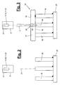
- the beam (3) can according to FIG. 3 with a vertical alignment component from above. Alternatively, it can also be incident from the side or from below, whereby the lower and upper parts (16, 17) are rotated accordingly and have a horizontal or upside-down arrangement.
- the high-energy beam (3) can occur in the joining process normal to the applied workpiece surface and be tracked during track tracing accordingly. He can alternatively come with a deviating from 90 ° Einstrahlwinkel to the workpiece surface and thus obliquely to her.
- the lower part (16) of the composite workpiece (15) has a narrow or thin shape and may for example have the shape of a slender protruding ridge.
- a bridge may be strip-shaped and have a greater continuous length, as in eg FIG. 9 is shown. Alternatively, the bridge can be shorter and have a kind of pinnacle profile.
- a web is also understood to mean a hump or another thin or slender elevation which has a small surface for the joint connection and the attachment surface to the upper part (17).
- the top of the bridge may be flat, curved, or otherwise profiled.
- the lower part (16) may also have a plurality of webs next to each other or in any other assignment, for example, on a support element (20), for example a bottom plate, arranged and welded, for example.
- the upper part (17) of the composite workpiece (15) can have a larger width dimension than the lower part (16) and covers it at least in the joining region, so that the joining region on the lower part (16) is no longer visible from the direction of incidence of the beam.
- the upper part (17) may be plate-shaped and have flat surfaces. It may alternatively have a curved or profiled shape, wherein the contact area is adapted to the provided for the joint connection free end of the web or base (16) and its shape and any contour. In the illustrated embodiment, a plate-shaped upper part (17) is flat on the flat web surface.
- FIGS. 4 and 5 illustrate an embodiment of a composite workpiece (15).
- This may for example be a component (21) of a vehicle, in particular a body part.
- a multi-part interior structure of a vehicle door is shown, which consists of the in FIG. 5 shown items, namely the inner panel with the lower part (16) and the window frame and the diagonal impact beam, both of which form an upper part (17).
- the inner panel is a support member (20) and carries a plurality of upstanding and the lower part (16) forming webs, which may be present individually and in places, but can also circulate like a frame on one or more sides around the window or wall openings.
- the upper parts (17) are concealed or blindly joined in the manner described below.
- the arrangement can also be reversed, wherein the webs (16) are located on the window frame and the diagonal impact beam and the inner panel forms the upper part (17).
- the high-energy beam (3) can be formed in any suitable manner. In the exemplary embodiment shown, it is a light beam, in particular a laser beam. Alternatively it can be an electron beam or another high-energy beam.
- the beam is generated by a beam source (4), for example a laser source, and fed via suitable lines, eg flexible optical fiber cables, to a jet head (5) and emitted by it to the workpiece (15) or its parts (16, 17).
- the beam (3) is focused or focused by the jet head (5). In this case, a plurality of beams (3) can be generated and emitted side by side.
- the jet head (5) is formed in the embodiment shown as a laser head and is guided by a multi-axis manipulator (6), which has a manipulator control (7).
- the manipulator (6) can have multiple rotational and / or translational axes. In the embodiment shown, an articulated arm robot with six or more axes is used.
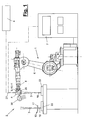
- the manipulator (6) has a manipulator hand (8), which in turn can have several axes. In the illustrated embodiment, the hand (8) has three orthogonal axes of rotation whose mobility in FIG. 1 is illustrated by arrows. At the output flange of the hand (8) of the jet head (5) is attached.
- the blasting head (5) is held and guided by the manipulator (6) at a greater distance relative to the workpiece parts (16, 17).
- the laser head (5) is designed here as a remote laser and has no physical contact with the workpiece parts (16,17).
- the working distance e.g. is more than 250 mm, preferably about 500 mm or more, the beam (3) can be angularly deflected and moved by this angular movement along a joining path (13) relative to the workpiece parts (16,17).
- the joining web (13) is a welding path or weld which extends along the web-like lower part (16) and runs, for example, in its central region.
- the joining track (13) has front and rear end points (14). It may be to act over the web length continuous joining track (13). Alternatively, an interrupted joining track (13), for example a stitching, is possible.
- the joining track (13) can have a straight course. It can alternatively meander or otherwise have a curved course.
- the blasting head (5) has an optical device (25) in the beam path (27) of the beam (3).
- This can be designed differently. It may include a focusing device, e.g. consists of a lens group with which the outgoing beam (3) is focused.
- the optical device (25) may alternatively or additionally comprise other optical elements, e.g. Mirror, exhibit.
- the said optical elements can be arranged stationary or movable.
- the focusing device may e.g. have curved mirrors. Pivoting mirrors can also be used as a so-called scanner device for angular deflection of the beam (3).
- the optical device (25) may have a fixed focal length. It may alternatively have a variable focal length, which can be varied during the joining process by a suitable adjustment. In this case, an autofocus system can be realized. Focal length changes are e.g. by changes in position of lenses and / or a fiber connector or a coupling point of the beam (3), by using one or more scattering lenses, by changing the position of mirrors, changes in the curvature of mirrors or the like possible.
- the optical device (25) may further comprise means for varying the size of the focus diameter and / or the focal spot of the beam (3) at its impact point have the workpiece surface or at the joint.
- the optical device (25) can eg according to WO 2006/015795 A1 be educated.
- the joining device (1) also has a measuring device (9), which is carried along by the manipulator (6).
- the measuring device is aligned in the emission direction of the beam (3) and has a measuring direction aligned with the beam direction or extending parallel thereto.
- the measuring device (9) in the jet head (5) is integrated or mounted in the area.
- the measuring device (9) is in the in FIG. 1 indicated manner with the manipulator control (7) connected by a wire or wirelessly.
- the measuring device (9) is designed as an optical detection device (10). This can have a different education and function. In the embodiment shown, it is designed as a digital camera and has an image recording device (11), which is designed, for example, as an image sensor with a dense pixel matrix and a high resolution. This can be, for example, a CCD or CMOS chip, which if necessary can also record and measure dynamically. With the image sensor, at least one image of the measuring range can be transmitted via an in FIG. 8 shown viewing window or measuring field are recorded. The one or more images can be stored by the measuring device (9) and output via suitable interfaces in file form or as an expression or the like. In addition, the distance of the lower part (16), for example based on the tool center point of the detection device (10), can be determined by the optical detection device (10).
- the optical detection device (10) also has an image evaluation (12) with which the web-like lower part (16) which appears optically in the viewing window (28) can be detected and measured.
- the image evaluation (12) can capture the regions and reference points of the lower part (16) that are relevant for joining, and measure them according to their size, in particular their width, as well as their shape, position and orientation.
- the detection and measurement takes place via easily recognizable and localisable shape features of the lower part (16), e.g. one or both upper longitudinal edges at the free ends of the web. Alternatively or additionally, other shape features can be detected.
- the viewing window (28) is assigned a suitable coordinate reference system.
- a beam point (29) can be arranged in the viewing window (28) at a central or other suitable location which is aligned with the beam path (27) of the high-energy beam (3).
- a crosshair can be spanned.
- the beam point (29) can form the reference point for determining and measuring the relevant reference points or contours of the lower part (16).
- the position values of the manipulator (6) and the tool center point of the optical detection device (10) can be used to determine absolute position data in space.
- the measurement can be done over the entire length of the joining region on the lower part (16) or in sections or punctually at one or more joints.
- the spatial position and the course of the lower part (16) can be detected.
- the shape and size of the lower part (16) can be detected.
- the width of the joining region for example the web width or sheet thickness there, can be measured.
- possibly parts and web deformations, eg inclinations, indentations, etc. can be detected metrologically.
- clear, easily recognizable shape features in the recorded image are determined with an image evaluation program, with their relative or absolute location coordinates being determined. From the evaluative comparison of relevant shape features, for example parallel longitudinal edges on the web upper side, the width of the intended joining region, eg the local web width, can be determined, for example by calculating the edge distance.
- the image evaluation (12) can also use these measurement data to determine the desired position of the joining path (13) to be followed by the beam (3) on the basis of predetermined criteria, e.g. a middle layer on the web surface, determine.
- the measuring device (9) or possibly the robot controller (7), e.g. the image evaluation (12), for this purpose, can have a suitable computing device with a program together with memory and interfaces for inputting and outputting data.
- the measuring device (9) or possibly the robot controller (7) can have a suitable program part for this purpose.
- This diameter can be adjusted during the joining process, for example via the optical device (25) and its adjusting device.
- the measuring device (9) or possibly the robot controller (7) can be connected for this purpose with this adjusting device for control purposes.
- process monitoring is possible online during beam joining.
- the processing site itself ie the workstation (32) and the local vapor capillary or the plasma can be observed and, for example, monitored. evaluated after color development.
- the joint seam can be viewed and tested for quality.
- the optical detection device (10) is arranged in the beam head (5) and coupled in alignment with the beam path (27) of the high-energy beam (3) by means of a coupling (26).
- the coupling (26) may e.g. a partially transparent, inclined mirror in the beam path (3), which directs the image of the measuring field to the optical detection device (10) and allows the beam (3) to pass.
- the mirror function can also be reversed, wherein the beam (3) is directed to exit the jet head (5).
- the manipulator (6) For measuring the jet head (5) with the measuring device (9) by the manipulator (6) positioned at a predetermined location relative to the lower part (16), wherein a location reference to a coordinate system of the manipulator (6) and the process-relevant tool center point (TCP) of the jet head (5) is produced.
- TCP process-relevant tool center point
- the relevant workpiece data in particular the shape, position and orientation of the lower part (16) can be recorded. Further, it is determined whether the beam spot (29) is located at the intended location or positional relation to the base (16).
- the lower part (16) and / or the to be traced joining path (13) can be searched.
- a predetermined joining path can be programmed and stored in the manipulator control (7).
- the programming being changed accordingly and aligned to be traced joining path (13) after the measurement result and stored.
- a component test can also be carried out for any errors, eg distortions or other deformations, of the lower part (16) in the joint area.
- the measuring device (9) is signal-technically connected to the manipulator control (7) and transmits this to the measurement and evaluation data. Possibly. the image evaluation can also be done in the manipulator control (7).
- the measuring field (28) is smaller than the joining area, then at the lower part (16) according to FIG. 9 several measurements are made, wherein the manipulator (6) the measuring device (9) successively positioned at corresponding measuring points.
- FIG. 2 illustrates how the measuring device (9) is positioned opposite to the lower part (16) to be measured. It can also be seen that a plurality of webs (16) can be arranged together on a support element, for example a bottom plate.
- a pilot beam (31) which, for example, is a visible light beam and is emitted in the beam path (27). Its optically visible impact point on the lower part (16) can be detected metrologically.
- the pilot beam (31) can be, for example, a laser beam with reduced energy or another beam coupled into the beam path (27).
- the joining device (1) furthermore has an illumination device (30) entrained by the manipulator (6), with which the measuring area on the lower part (16) can be illuminated.
- the illumination device (30) is in FIG. 1 schematically shown. It can be designed and arranged as desired and has a plurality of suitable lighting elements, such as headlights or the like. Several light elements can radiate from different directions to the measuring area and illuminate this largely shadowless.
- the illumination device (30) can be attached to the blasting head (5) or to the hand (8) and have a frame-like or cantilever-like frame on which the lighting elements are optionally arranged adjustably and thereby positioned and oriented with a suitable position and orientation to the measuring area.
- the illumination device (30) can be distanced laterally from the blasting head (5) or the hand (8), wherein the lighting elements can also have a mutual distance.
- the measurement of the lower part (16) positioned on a clamping (22) in a predetermined position forms the first process step.
- all intended joining areas are measured completely or in places, with interpolation possibly being made for the formation of the route.
- additional processing e.g. Joining sub-parts (16) with each other, joining other workpiece parts or the like. Be performed.
- the upper part (17) is placed on the lower part (16) and tensioned or fixed in another way.
- This can be done manually or mechanically by a robot or the like, e.g. also from the manipulator (6) with a corresponding tool done.
- the upper part (17) is joined to the lower part (16), the beam (3) being guided along the stored joining track (13) and directed onto the upper part (17).
- the upper part (17) lies with its front side (18) on the lower part (16).
- the beam (3) is directed from the outside to the back (19) of the upper part (17) over the joint, wherein the parts (16) are hidden or blind joined.
- the beam (3) can be focused appropriately.
- at the working or joint (32) in FIG. 3 formed molten bath (33) formed.
- On the right web (16) an already created joint connection is indicated.
- the focus (34) of the high-energy beam (3) is suitably positioned in order to have a correct and optimally optimal energy input at the connection point.
- the focus (34) is e.g. placed at this contact point or connection point between the workpiece parts (16,17) by appropriate adjustment of the optical device (25) with its focusing device.
- the focus (34) can be displaced by changing the working distance by means of a manipulator movement.
- the focus (34) may be slightly above or below this location.
- An energy-rich beam (3) in particular a laser beam, also has, depending on the beam quality, an area in the beam longitudinal direction about the focal point (34), in which the beam diameter is comparatively constant.
- This beam range is referred to as the Raleigh length and may be e.g. between +/- 2 mm and +/- 8 mm. This depends on the beam source (4) used, the optical device (25) and other factors.
- the focal point (34) can be adjusted in its position so that the contact and connection point is in the range of Raleighin.
- the energy input depends on the beam diameter at the contact and joint. From the beam or focus diameter in turn depends on the resulting diameter of the Anbindequeritess.
- the beam diameter in the focus or Raleigh range can the sheet thickness of the lower part or web (16) are adjusted, which also results in an adaptation of the Anbinde- or joining cross-section.
- the diameter of the joining or joining cross section should be equal to or smaller than the web width.
- the focus diameter and the joining or joining cross-section at the T-joint can be very small. With a diameter of the focus (34) or the Raleigh range of e.g. 0.6, the associated diameter of the Anbindequeritess be approximately 0.9 mm.
- the web width can be correspondingly thin and e.g. about 1 mm. With a land width of e.g. 0.8 mm, a diameter of the attachment cross-section of 0.6 mm and a beam diameter of about 0.4 mm are advantageous. For a larger land width of e.g. 1.5 mm, 1.2 mm diameter of the attachment cross section and 0.8 mm beam diameter may be favorable.
- the top (17) may have an equal or greater thickness, e.g. about 0.8 to 1.5 mm.
- the beam (3) can be deflected and guided during the joining exclusively or substantially by an angular movement along the track (13) for the purpose of following the joining track (13).
- This can e.g. through the optical device (25), this being e.g. has a scanner optics with one or more pivotable mirrors or other optical elements.
- the beam deflection can take place by a rotation of the manipulator hand (8) about one or more of its rotational axes.
- the focal length of the optical device (25) is preferably about 500 mm and can also be significantly larger, for example, 1,000 mm, 1,500 mm and more. It can also be smaller and for example 250 mm. Accordingly, the working distance is correspondingly large.
- the beam (3) can cover large paths with its impact point on the upper part (17) through small angular deflections and be guided and controlled very quickly and accurately. Due to the angular deflection, the angle of incidence of the beam (3) on the upper part (17) can change.
- the beam power and / or the path velocity of the beam (3) or the welding speed can be tracked in order to introduce the desired path energy at the upper part (17). This is also possible in conjunction with other beam guiding techniques.
- the focal length and possibly also the focus diameter can be tracked depending on the deflection or angle of incidence via an autofocus system.
- the position of the focus (34) in the beam direction on the workpiece (15, 16, 17) can be adjusted via a focal length adjustment of the optical device (25) and / or by a change of the working distance, e.g. be effected by a movement of the manipulator (6).
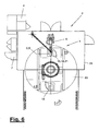
- FIG. 6 shows schematically the formation of a joining station (2), for example a laser welding station.
- the station (2) is surrounded on the outside by a boundary or a protective device, for example a laser cabin (24).
- the joining device (1) is largely arranged in the interior, wherein the laser source (4) can be located outside and is connected via a flexible line with a rotatable gallows with the remote laser head (5) on the manipulator (6).
- the joining station (2) also has a component feed (23), which is designed, for example, as a turntable with two or more clamping points, on which at least the workpiece parts (16) are inserted by a worker. At this point, the finished welded composite workpieces (15) can be removed again and transported away for further processing.
- the Laying the tops (17) after the measurement of the lower parts (16) can be done within the station by the manipulator (6) or other automatic device.
- the component feeder (23) can rotate and the worker places the upper part (17) on and clamps it, while at the other clamping point the next lower part (16) is measured or joined.
- the lower part (16) may have an angled or curved shape, wherein the web width may also change.
- the lower part (16) can have a plurality of webs and e.g. be designed as a U or W profile.
- the lower part (16) may have an open or closed frame shape. It can also be connected to other workpiece parts.
- the beam (3) can also be guided along the joining track (13) in a manner other than by beam deflection. This is e.g. by a driving and / or pivoting movement of the manipulator (6) with its other axes possible.
- the angle of incidence of the beam (3) on the upper part (17) can remain constant or change only slightly.
- the angle of incidence may be aligned in particular perpendicular to the relevant workpiece surface. Alternatively, it may have an inclined position and e.g. be inclined longitudinally or transversely to the web course.
Description
Die Erfindung betrifft ein Verfahren und eine Einrichtung zum Fügen von Werkstücken mit den Merkmalen im Oberbegriff des Verfahrens- und Vorrichtungshauptanspruchs.The invention relates to a method and a device for joining workpieces with the features in the preamble of the method and device main claim.
Aus der
Die
Aus der Praxis ist es ferner bekannt, Bauteile mit Laserstrahl unter Bildung von Kehlnähten zu schweißen. Das Laserstrahlschweißen wird auch für Überlappstöße im Kantenbereich eingesetzt, wobei die Schweißnaht anhand der eng benachbarten Werkstückkante ermittelt wird. Hierbei gibt es immer einen genügend breiten Überlappungsbereich, so dass eine korrekte Schweißnaht kein Problem ist.From practice, it is also known to weld components with laser beam to form fillet welds. Laser beam welding is also used for lap joints in the edge area, whereby the weld seam is determined on the basis of the closely adjacent edge of the workpiece. There is always a sufficiently wide overlap area, so that a correct weld is not a problem.
Es ist Aufgabe der vorliegenden Erfindung, eine verbesserte Fügetechnik mit breiteren Einsatzmöglichkeiten aufzuzeigen.It is an object of the present invention to provide an improved joining technique with a wider range of applications.
Die Erfindung löst diese Aufgabe mit den Merkmalen im Verfahrens- und Vorrichtungshauptanspruch.
Die beanspruchte Fügetechnik erlaubt es, auch dünne oder schmale Teile eines Werkstücks mit darüber liegenden breiteren Werkstückteilen verdeckt und vom breiteren Werkstückteil her zu fügen. Hierbei können insbesondere schmale Stege mit plattenförmigen Oberteilen verdeckt gefügt werden. Durch die vor dem Strahlfügen stattfindende Vermessung und Ausrichtung kann die Fügebahn sicher eingehalten werden, auch wenn beim Fügen selbst das schmale oder dünne Unterteil nicht mehr sichtbar ist und während des Verfolgens der Fügebahn mit dem energiereichen Strahl nicht mehr online gesucht oder kontrolliert werden kann.The invention solves this problem with the features in the method and device main claim.
The claimed joining technique makes it possible to conceal even thin or narrow parts of a workpiece with overlying wider workpiece parts and add from the wider workpiece part. In particular, narrow webs can be concealed with plate-shaped tops. Due to the measurement and alignment taking place before blasting, the joining web can be safely adhered to, even if the narrow or thin lower part is no longer visible during joining and can no longer be searched or checked online during the tracking of the joining web with the high-energy jet.
Durch die Vermessung der vorgesehenen Fügebereiche der Werkstückteile, insbesondere Stege, können neben der Steglage und dem Stegverlauf auch Größe, insbesondere die Breite, und ggf. die Form der Stege erfasst werden. Hieraus lässt sich nicht nur der Verlauf der Fügebahn, insbesondere Schweißbahn, und deren Mittellage am Steg ermitteln, sondern auch die geeignete Größe, insbesondere der Durchmesser, des Fokus- oder Brennflecks des energiereichen Strahls und ggf. die Brennweiteneinstellung bestimmen. Der besagte Durchmesser kann an die Wandstärke des Stegs angepasst werden, um die Qualität der Fügeverbindung zu optimieren.By measuring the intended joining areas of the workpiece parts, in particular webs, in addition to the web position and the web course, it is also possible to detect the size, in particular the width, and possibly the shape of the webs. From this it is possible to determine not only the course of the joining track, in particular the welding track, and its center position on the web, but also the suitable size, in particular the diameter, of the focus or focal spot of the web high-energy beam and, if necessary, determine the focal length setting. The said diameter can be adapted to the wall thickness of the web to optimize the quality of the joint connection.
Durch die verdeckte Fügetechnik ist es möglich, auch schwierige Werkstückkonfigurationen zu fügen, bei denen ein Zugang der Fügestelle von der Seite des schmalen oder dünnen Unterteils aus nicht möglich oder nicht erwünscht ist.The concealed joining technique makes it possible to add even difficult workpiece configurations where access of the joint from the side of the narrow or thin base is not possible or desirable.
Die beanspruchte Fügetechnik lässt sich in Verbindung mit unterschiedlichen Fügeverfahren einsetzen, wobei der energiereiche Strahl ebenfalls unterschiedlich ausgebildet sein kann, z.B. als Lichtstrahl, insbesondere Laserstrahl, als Elektronenstrahl oder dergleichen. Als Fügeverfahren kommt das Schweißen mit derartigen energiereichen Strahlen, aber auch das Löten, Kleben oder dergleichen andere Fügeverfahren in Betracht. Mit dem energiereichen Strahl können im Anbindungsquerschnitt auch Löcher durch die Teile der Querschnittpaarung gebohrt werden.The claimed joining technique can be used in conjunction with different joining methods, wherein the high-energy beam can also be designed differently, e.g. as a light beam, in particular a laser beam, as an electron beam or the like. As a joining process, welding with such high-energy radiation, but also the soldering, gluing or the like other joining processes come into consideration. With the high-energy beam, holes can also be drilled through the parts of the cross-section pairing in the connection cross-section.
Die beanspruchte Fügetechnik bietet eine hohe Betriebssicherheit und Fügequalität. Die Anbindungsquerschnitte können sehr klein sein. Dies bringt auch Vorteile für das Ausgasen von Beschichtungen, z.B. Korrosionsschutz- oder Zinkbeschichtungen, an der Fügestelle mit sich. Durch das verdeckte Fügen vom Werkstückoberteil her kann das dünne oder schmale Unterteil geschont werden. Der Fügeprozess kann außerdem schnell von statten gehen. Hierfür ist eine Strahlablenkung durch kleine und schnelle Handachsenbewegungen eines Manipulators oder durch eine optische Einrichtung, insbesondere einer Scanneroptik mit ein oder mehreren schwenkbaren Spiegeln oder dergleichen von Vorteil.The claimed joining technique offers a high level of operational reliability and joining quality. The connection cross sections can be very small. This also brings advantages for the outgassing of coatings, such as corrosion protection or zinc coatings, at the joint with it. Due to the hidden joining of the upper part of the workpiece, the thin or narrow lower part can be spared. The joining process can also be done quickly. For this purpose, a beam deflection by small and fast hand axis movements of a manipulator or by an optical device, in particular a scanner optics with one or more pivotable mirrors or the like is advantageous.
Die optische Einrichtung erlaubt außerdem eine Änderung der Brennweite für den emittierten energiereichen Strahl. Hierdurch können z.B. durch die Strahlauslenkung bedingte Änderungen des Arbeitsabstandes kompensiert werden. Andererseits ist auch ein bewusstes Defokussieren möglich. Ferner kann mit der optischen Einrichtung auch bei Bedarf die Größe des Brennflecks bzw. der Auftreffstelle des Strahls auf der Werkstückoberfläche beeinflusst werden. Dies kann unabhängig davon geschehen, ob sich zugleich die Brennweite ändert oder konstant bleibt. Bei Brennweitenänderungen kann andererseits die Brennflächengröße konstant gehalten werden.The optical device also allows a change in the focal length for the emitted high-energy beam. As a result, e.g. compensated by the beam deflection changes in the working distance. On the other hand, a conscious defocusing is possible. Furthermore, the size of the focal spot or of the point of impact of the beam on the workpiece surface can also be influenced with the optical device when required. This can happen regardless of whether the focal length changes or remains constant at the same time. On the other hand, with focal length changes, the focal area size can be kept constant.
Für die genaue Vermessung des Werkstückunterteils ist es vorteilhafterweise vorgesehen, die Messeinrichtung mit dem Manipulator mitzuführen. Dies verbessert die Genauigkeit gegenüber einer externen und z.B. stationären Messvorrichtung. Von besonderem Vorteil ist es, dass die Messeinrichtung derart angeordnet ist, dass sie in Richtung des energiereichen Strahls wirkt. Hierdurch kann der für die Fügebahn maßgebliche Werkstückbereich direkt und mit gleicher Ausrichtung wie der energiereiche Strahl vermessen werden. Besonders günstig ist der Einsatz einer optischen Erfassungseinrichtung, die in den Strahlengang eingekoppelt werden kann. Sie blickt fluchtend mit dem Strahl auf das zu vermessende Werkstück. Dies bietet eine weitere Steigerung der Messgenauigkeit.For the exact measurement of the workpiece lower part, it is advantageously provided to carry the measuring device with the manipulator. This improves the accuracy over an external and e.g. stationary measuring device. It is particularly advantageous that the measuring device is arranged such that it acts in the direction of the high-energy beam. As a result, the relevant workpiece area for the joining path can be measured directly and with the same orientation as the high-energy beam. Particularly favorable is the use of an optical detection device which can be coupled into the beam path. It looks in alignment with the beam at the workpiece to be measured. This provides a further increase in measurement accuracy.
Die optische Erfassungseinrichtung ist bevorzugt als Digitalkamera ausgebildet und besitzt eine Bildaufnahmeeinrichtung in Form eines Bildsensors oder Chips mit einer dichten Pixelmatrix und einer hohen Auflösung. Hiermit kann durch ein Sichtfenster oder ein Messfeld ein größerer Ausschnitt des zu vermessenden Werkstücks aufgenommen und vermessen werden. Hierfür kann eine Bildauswertung vorhanden sein, die aus dem aufgenommenen Bild die relevanten Merkmale des zu vermessenden Unterteils, insbesondere die Form, Lage und Ausrichtung sowie den Abstand ermittelt. Aus diesen Merkmalen kann aus der Bildauswertung auch gleich die Soll-Lage der Fügebahn ermittelt werden. Die Messergebnisse und ggf. auch die ermittelten Daten der Fügebahn können an die Manipulatorsteuerung oder eine andere geeignete Steuerung zur Beeinflussung und Führung des energiereichen Strahls übermittelt werden.The optical detection device is preferably designed as a digital camera and has an image recording device in the form of an image sensor or chip with a dense pixel matrix and a high resolution. Hereby, a larger section of the workpiece to be measured can be recorded and measured by a viewing window or a measuring field. For this purpose, an image analysis can be present, which from the recorded image the relevant characteristics of measuring lower part, in particular the shape, position and orientation and determines the distance. From these characteristics, the desired position of the joining track can also be determined immediately from the image evaluation. The measurement results and possibly also the determined data of the joining track can be transmitted to the manipulator control or another suitable control for influencing and guiding the high-energy beam.
Mit der beanspruchten Messtechnik kann einerseits das Werkstück-Unterteil und/oder die Soll-Lage der Fügebahn gesucht werden. Alternativ können die Messergebnisse und die ermittelten Daten mit einer in der Manipulatorsteuerung vorprogrammierten Fügebahn verglichen werden, wobei die vorprogrammierte Bahn beim Auftreten von Abweichungen entsprechend korrigiert und nachgeführt wird. In allen Varianten ergibt sich eine optimale Ermittlung der Soll-Lage der Fügebahn, die dann beim verdeckten Fügen mit größtmöglicher Sicherheit vom energiereichen Strahl verfolgt werden kann.With the claimed measuring technique, on the one hand, the workpiece lower part and / or the desired position of the joining web can be searched. Alternatively, the measurement results and the determined data can be compared with a pre-programmed in the manipulator control path, the preprogrammed path is corrected and tracked when deviations occur. In all variants, there is an optimal determination of the desired position of the joining track, which can then be tracked by the high-energy beam with the utmost security in concealed joining.
Die Messgenauigkeit wird durch eine geeignete Ausleuchtung des Messbereichs verbessert. Hierfür ist eine vom Manipulator mitgeführte Beleuchtungseinrichtung vorgesehen, die auf den Messbereich gerichtet ist. Die Anordnung von mehreren, aus verschiedenen Richtungen einstrahlenden Leuchtelementen bietet den Vorteil, dass die Konturenschärfe der relevanten Bezugspunkte des Werkstück-Unterteils, z.B. der Kanten am freien und zu fügenden Ende eines Stegs, verbessert wird. Schattenbildungen, die möglicherweise das Messergebnis beeinträchtigen könnten, werden somit vermieden oder zumindest minimiert.The measuring accuracy is improved by a suitable illumination of the measuring range. For this purpose, a guided by the manipulator lighting device is provided, which is directed to the measuring range. The arrangement of a plurality of luminous elements radiating in different directions offers the advantage that the sharpness of the contours of the relevant reference points of the workpiece lower part, e.g. the edges at the free and mating end of a web is improved. Shadows that could potentially affect the measurement result are thus avoided or at least minimized.
In den Unteransprüchen sind weitere vorteilhafte Ausgestaltungen der Erfindung angegeben.In the subclaims further advantageous embodiments of the invention are given.
Die Erfindung ist in den Zeichnungen beispielsweise und schematisch dargestellt. Im einzelnen zeigen:
- Figur 1:
- eine Fügeeinrichtung in einer Seitenansicht,
- Figur 2:
- eine schematische Darstellung der Vermessung eines stegförmigen Unterteils,
- Figur 3:
- eine schematische Darstellung des verdeckten Schweißens eines aufgelegten Oberteils,
Figur 4 und 5:- Darstellungen eines Verbund-Werkstücks und seiner Teile,
- Figur 6:
- eine schematische Draufsicht auf eine Fügestation,
- Figur 7:
- eine schematische Darstellung eines Strahlkopfes mit einer integrierten Messeinrichtung,
- Figur 8:
- eine schematische Darstellung eines Sichtfensters oder Messfelds der Messeinrichtung und
- Figur 9:
- eine Draufsicht auf das zu fügende Werkstückunterteil mit mehreren Stellungen des Messfensters.
- FIG. 1:
- a joining device in a side view,
- FIG. 2:
- a schematic representation of the measurement of a web-shaped lower part,
- FIG. 3:
- a schematic representation of the hidden welding of an applied shell,
- FIGS. 4 and 5:
- Representations of a composite workpiece and its parts,
- FIG. 6:
- a schematic plan view of a joining station,
- FIG. 7:
- a schematic representation of a jet head with an integrated measuring device,
- FIG. 8:
- a schematic representation of a viewing window or measuring field of the measuring device and
- FIG. 9:
- a plan view of the workpiece bottom part to be joined with multiple positions of the measuring window.
Die Erfindung betrifft ein Verfahren und eine Fügeeinrichtung (1) zum Fügen von Werkstücken (15) mit mindestens einem energiereichen Strahl (3). Die Erfindung betrifft ferner eine Fügestation, die mit ein oder mehreren solcher Fügeeinrichtungen (1) ausgerüstet ist.The invention relates to a method and a joining device (1) for joining workpieces (15) with at least one high-energy beam (3). The invention further relates to a joining station with or a plurality of such joining devices (1) is equipped.
Das Werkstück (15) wird durch Fügen mindestens eines sog. Unterteils (16) und mindestens eines Oberteils (17) gebildet. Das Oberteil (17) liegt aus der Einfallrichtung des energiereichen Strahls (3) her gesehen über dem Unterteil (16) und deckt dieses ab. Der Strahl (3) kann gemäß
Der energiereiche Strahl (3) kann im Fügeprozess normal zur beaufschlagten Werkstückoberfläche einfallen und während der Bahnverfolgung entsprechend nachgeführt werden. Er kann alternativ mit einem von 90° abweichenden Einstrahlwinkel zur Werkstückoberfläche und damit schräg zu ihr einfallen.The high-energy beam (3) can occur in the joining process normal to the applied workpiece surface and be tracked during track tracing accordingly. He can alternatively come with a deviating from 90 ° Einstrahlwinkel to the workpiece surface and thus obliquely to her.
Das Unterteil (16) des Verbundwerkstücks (15) hat eine schmale oder dünne Form und kann z.B. die Gestalt eines schlanken abstehenden Steges besitzen. Ein solcher Steg kann leistenförmig sein und eine größere durchgehende Länge haben, wie sie z.B. in
Das Oberteil (17) des Verbundwerkstücks (15) kann eine größere Breitenabmessung als das Unterteil (16) haben und deckt dieses zumindest im Fügebereich ab, so dass der Fügebereich am Unterteil (16) aus der Einfallsrichtung des Strahls her nicht mehr sichtbar ist. Das Oberteil (17) kann plattenförmig sein und ebene Oberflächen aufweisen. Es kann alternativ eine gebogene oder profilierte Form haben, wobei der Kontaktbereich an das für die Fügeverbindung vorgesehene freie Ende des Stegs oder Unterteils (16) und dessen Formgebung und eventuelle Kontur angepasst ist. Im gezeigten Ausführungsbeispiel liegt ein plattenförmiges Oberteil (17) plan auf der ebenen Stegoberfläche.The upper part (17) of the composite workpiece (15) can have a larger width dimension than the lower part (16) and covers it at least in the joining region, so that the joining region on the lower part (16) is no longer visible from the direction of incidence of the beam. The upper part (17) may be plate-shaped and have flat surfaces. It may alternatively have a curved or profiled shape, wherein the contact area is adapted to the provided for the joint connection free end of the web or base (16) and its shape and any contour. In the illustrated embodiment, a plate-shaped upper part (17) is flat on the flat web surface.
Der energiereiche Strahl (3) kann in beliebig geeigneter Weise ausgebildet sein. Im gezeigten Ausführungsbeispiel handelt es sich um einen Lichtstrahl, insbesondere um einen Laserstrahl. Alternativ kann es ein Elektronenstrahl oder ein sonstiger energiereicher Strahl sein. Der Strahl wird von einer Strahlquelle (4), z.B. einer Laserquelle, erzeugt und über geeignete Leitungen, z.B. flexible Lichtfaserkabel, einem Strahlkopf (5) zugeführt und von diesem zum Werkstück (15) bzw. dessen Teilen (16,17) emittiert. Der Strahl (3) wird vom Strahlkopf (5) gebündelt oder fokussiert. Hierbei können auch mehrere Strahlen (3) erzeugt und nebeneinander emittiert werden.The high-energy beam (3) can be formed in any suitable manner. In the exemplary embodiment shown, it is a light beam, in particular a laser beam. Alternatively it can be an electron beam or another high-energy beam. The beam is generated by a beam source (4), for example a laser source, and fed via suitable lines, eg flexible optical fiber cables, to a jet head (5) and emitted by it to the workpiece (15) or its parts (16, 17). The beam (3) is focused or focused by the jet head (5). In this case, a plurality of beams (3) can be generated and emitted side by side.
Der Strahlkopf (5) ist im gezeigten Ausführungsbeispiel als Laserkopf ausgebildet und wird von einem mehrachsigen Manipulator (6) geführt, der eine Manipulatorsteuerung (7) hat. Der Manipulator (6) kann mehrere rotatorische und/oder translatorische Achsen haben. Im gezeigten Ausführungsbeispiel kommt ein Gelenkarmroboter mit sechs oder mehr Achsen zum Einsatz. Der Manipulator (6) besitzt eine Manipulatorhand (8), die ihrerseits mehrere Achsen haben kann. Im gezeigten Ausführungsbeispiel hat die Hand (8) drei orthogonale Drehachsen, deren Beweglichkeit in
Der Strahlkopf (5) wird vom Manipulator (6) mit einem größeren Abstand gegenüber den Werkstückteilen (16,17) gehalten und geführt. Der Laserkopf (5) ist hierbei als Remote-Laser ausgebildet und hat keinen Berührungskontakt zu den Werkstückteilen (16,17). Durch den Arbeitsabstand, der z.B. mehr als 250 mm, vorzugsweise ca. 500 mm oder mehr beträgt, kann der Strahl (3) winkelig ausgelenkt und durch diese Winkelbewegung entlang einer Fügebahn (13) gegenüber den Werkstückteilen (16,17) bewegt werden.The blasting head (5) is held and guided by the manipulator (6) at a greater distance relative to the workpiece parts (16, 17). The laser head (5) is designed here as a remote laser and has no physical contact with the workpiece parts (16,17). By the working distance, e.g. is more than 250 mm, preferably about 500 mm or more, the beam (3) can be angularly deflected and moved by this angular movement along a joining path (13) relative to the workpiece parts (16,17).
Im gezeigten Ausführungsbeispiel des Laserschweißens ist die Fügebahn (13) eine Schweißbahn oder Schweißnaht, die sich längs des stegartigen Unterteils (16) erstreckt und z.B. in dessen mittleren Bereich verläuft. Die Fügebahn (13) hat vordere und hintere Endpunkte (14). Es kann sich um eine über die Steglänge durchgehende Fügebahn (13) handeln. Alternativ ist eine unterbrochene Fügebahn (13), z.B. eine Steppnaht, möglich. Die Fügebahn (13) kann einen geraden Verlauf haben. Sie kann alternativ mäandrieren oder einen anderweitig gekrümmten Verlauf haben. Am Werkstück (15,16,17) bestehen entsprechende durchgehende oder unterbrochene Fügebereiche, insbesondere Schweißbereiche.In the illustrated embodiment of the laser welding, the joining web (13) is a welding path or weld which extends along the web-like lower part (16) and runs, for example, in its central region. The joining track (13) has front and rear end points (14). It may be to act over the web length continuous joining track (13). Alternatively, an interrupted joining track (13), for example a stitching, is possible. The joining track (13) can have a straight course. It can alternatively meander or otherwise have a curved course. On the workpiece (15,16,17) there are corresponding continuous or interrupted joining areas, in particular welding areas.
Der Strahlkopf (5) besitzt eine optische Einrichtung (25) im Strahlengang (27) des Strahls (3). Diese kann unterschiedlich ausgebildet sein. Sie kann eine Fokussiereinrichtung beinhalten, die z.B. aus einer Linsengruppe besteht, mit welcher der austretende Strahl (3) fokussiert wird. Die optische Einrichtung (25) kann alternativ oder zusätzlich andere Optikelemente, z.B. Spiegel, aufweisen. Die genannten optischen Elemente können stationär oder beweglich angeordnet sein. Die Fokussiereinrichtung kann z.B. gekrümmte Spiegel aufweisen. Schwenkbare Spiegel können auch als sog. Scannereinrichtung zur Winkelablenkung des Strahls (3) benutzt werden.The blasting head (5) has an optical device (25) in the beam path (27) of the beam (3). This can be designed differently. It may include a focusing device, e.g. consists of a lens group with which the outgoing beam (3) is focused. The optical device (25) may alternatively or additionally comprise other optical elements, e.g. Mirror, exhibit. The said optical elements can be arranged stationary or movable. The focusing device may e.g. have curved mirrors. Pivoting mirrors can also be used as a so-called scanner device for angular deflection of the beam (3).
Die optische Einrichtung (25) kann eine feste Brennweite haben. Sie kann alternativ eine veränderliche Brennweite besitzen, die während des Fügeprozesses durch eine geeignete Verstelleinrichtung variiert werden kann. Hierbei kann auch ein Autofokus-System realisiert werden. Brennweitenänderungen sind z.B. durch Lageänderungen von Linsen und/oder einem Faserstecker bzw. einem Einkoppelpunkt des Strahls (3), durch Einsatz von ein oder mehreren Streulinsen, durch Lageänderung von Spiegeln, Krümmungsänderungen von Spiegeln oder dergleichen möglich.The optical device (25) may have a fixed focal length. It may alternatively have a variable focal length, which can be varied during the joining process by a suitable adjustment. In this case, an autofocus system can be realized. Focal length changes are e.g. by changes in position of lenses and / or a fiber connector or a coupling point of the beam (3), by using one or more scattering lenses, by changing the position of mirrors, changes in the curvature of mirrors or the like possible.
Die optische Einrichtung (25) kann ferner eine Einrichtung zur Veränderung der Größe des Fokusdurchmessers und/oder des Brennflecks des Strahls (3) an dessen Auftreffpunkt an der Werkstückoberfläche oder an der Fügestelle aufweisen. Die optische Einrichtung (25) kann z.B. entsprechend der
Die Fügeeinrichtung (1) weist ferner eine Messeinrichtung (9) auf, die vom Manipulator (6) mitgeführt wird. Die Messeinrichtung ist in Emissionsrichtung des Strahls (3) ausgerichtet und hat eine mit der Strahlrichtung fluchtende oder parallel dazu verlaufende Messrichtung. Günstigerweise ist die Messeinrichtung (9) im Strahlkopf (5) integriert oder in dessen Bereich angebracht. Die Messeinrichtung (9) ist in der in
Die Messeinrichtung (9) ist als optische Erfassungseinrichtung (10) ausgebildet. Diese kann eine unterschiedliche Ausbildung und Funktion haben. Im gezeigten Ausführungsbeispiel ist sie als Digitalkamera ausgeführt und besitzt eine Bildaufnahmeeinrichtung (11), die z.B. als Bildsensor mit einer dichten Pixelmatrix und einer hohen Auflösung gestaltet ist. Dies kann z.B. ein CCD- oder CMOS-Chip sein, der ggf. auch dynamisch aufnehmen und messen kann. Mit dem Bildsensor kann mindestens ein Bild des Messbereichs über ein in
Die optische Erfassungseinrichtung (10) weist ferner eine Bildauswertung (12) auf, mit der das im Sichtfenster (28) optisch erscheinende stegartige Unterteil (16) erfasst und vermessen werden kann. Die Bildauswertung (12) kann die zum Fügen relevanten Bereiche und Bezugspunkte des Unterteils (16) erfassen und nach ihrer Größe, insbesondere ihrer Breite, sowie nach ihrer Form, Lage und Ausrichtung vermessen. Die Erfassung und Vermessung erfolgt über gut erkennbare und lokalisierbare Formmerkmale des Unterteils (16), z.B. eine oder beide obere Längskanten an den freien Enden des Stegs. Alternativ oder zusätzlich können andere Formmerkmale erfasst werden.The optical detection device (10) also has an image evaluation (12) with which the web-like lower part (16) which appears optically in the viewing window (28) can be detected and measured. The image evaluation (12) can capture the regions and reference points of the lower part (16) that are relevant for joining, and measure them according to their size, in particular their width, as well as their shape, position and orientation. The detection and measurement takes place via easily recognizable and localisable shape features of the lower part (16), e.g. one or both upper longitudinal edges at the free ends of the web. Alternatively or additionally, other shape features can be detected.
Für die Erfassung und Vermessung ist dem Sichtfenster (28) ein geeignetes Koordinatenbezugssystem zugeordnet. Beispielsweise kann im Sichtfenster (28) an zentraler oder anderer geeigneter Stelle ein Strahlpunkt (29) angeordnet sein, der mit dem Strahlengang (27) des energiereichen Strahls (3) fluchtet. Im Strahlpunkt (29) kann auch ein Fadenkreuz aufgespannt sein. Der Strahlpunkt (29) kann den Bezugspunkt zur Ermittlung und Vermessung der relevanten Bezugspunkte oder Konturen des Unterteils (16) bilden. Die Positionswerte des Manipulators (6) und des Tool-Center-Points der optischen Erfassungseinrichtung (10) können dabei zur Ermittlung absoluter Positionsdaten im Raum herangezogen werden.For detection and measurement, the viewing window (28) is assigned a suitable coordinate reference system. For example, a beam point (29) can be arranged in the viewing window (28) at a central or other suitable location which is aligned with the beam path (27) of the high-energy beam (3). In the beam point (29) and a crosshair can be spanned. The beam point (29) can form the reference point for determining and measuring the relevant reference points or contours of the lower part (16). The position values of the manipulator (6) and the tool center point of the optical detection device (10) can be used to determine absolute position data in space.
Die Vermessung kann über die gesamte Länge des Fügebereichs am Unterteil (16) oder abschnittsweise oder punktuell an einer oder an mehreren Fügestellen geschehen. Bei der Vermessung können die räumliche Lage und der Verlauf des Unterteils (16) erfasst werden. Außerdem kann bei der Vermessung die Form und Größe des Unterteils (16) erfasst werden. Insbesondere kann die Breite des Fügebereichs, z.B. die dortige Stegbreite bzw. Blechdicke, gemessen werden. Auch evtl. Teile- und Stegverformungen, z.B. Schräglagen, Einbuchtungen etc. können messtechnisch erfasst werden. Bei der Vermessung werden eindeutige, gut erkennbare Formmerkmale im aufgenommenen Bild mit einem Bildauswertungsprogramm ermittelt, wobei deren relative oder absolute Ortskoordinaten ermittelt werden. Aus dem auswertenden Vergleich relevanter Formmerkmale, z.B. paralleler Längskanten an der Stegoberseite kann die Breite des vorgesehenen Fügebereichs, z.B. die örtliche Stegbreite, bestimmt werden, indem z.B. der Kantenabstand berechnet wird.The measurement can be done over the entire length of the joining region on the lower part (16) or in sections or punctually at one or more joints. During the survey, the spatial position and the course of the lower part (16) can be detected. In addition, during the measurement, the shape and size of the lower part (16) can be detected. In particular, the width of the joining region, for example the web width or sheet thickness there, can be measured. Also possibly parts and web deformations, eg inclinations, indentations, etc. can be detected metrologically. During the measurement, clear, easily recognizable shape features in the recorded image are determined with an image evaluation program, with their relative or absolute location coordinates being determined. From the evaluative comparison of relevant shape features, for example parallel longitudinal edges on the web upper side, the width of the intended joining region, eg the local web width, can be determined, for example by calculating the edge distance.
Von der Bildauswertung (12) kann nicht nur das Unterteil (16) im Sichtfenster (28) erfasst und vermessen werden. Die Bildauswertung (12) kann außerdem anhand dieser Messdaten die Soll-Lage der vom Strahl (3) zu verfolgenden Fügebahn (13) anhand vorgegebener Kriterien, z.B. eine Mittellage an der Stegoberfläche, ermitteln. Die Messeinrichtung (9) oder ggf. die Robotersteuerung (7), z.B. die Bildauswertung (12), kann zu diesem Zweck eine geeignete Recheneinrichtung mit einem Programm nebst Speicher und Schnittstellen zur Ein- und Ausgabe von Daten aufweisen.From the image analysis (12) not only the lower part (16) in the viewing window (28) can be detected and measured. The image evaluation (12) can also use these measurement data to determine the desired position of the joining path (13) to be followed by the beam (3) on the basis of predetermined criteria, e.g. a middle layer on the web surface, determine. The measuring device (9) or possibly the robot controller (7), e.g. the image evaluation (12), for this purpose, can have a suitable computing device with a program together with memory and interfaces for inputting and outputting data.
Bei der Vermessung kann ferner anhand der ermittelten Größe, insbesondere Breite, des Fügebereichs der hierfür geeignete oder erforderliche Fokus- oder Brennfleckdurchmesser von der Messeinrichtung (9) oder ggf. der Robotersteuerung (7) in der nachfolgend erläuterten Weise bestimmt werden. Die Messeinrichtung (9) oder ggf. die Robotersteuerung (7), z.B. die Bildauswertung (12), kann hierfür ein geeignetes Programmteil aufweisen. Dieser Durchmesser kann beim Fügeprozess eingestellt werden, z.B. über die optische Einrichtung (25) und deren Verstelleinrichtung. Die Messeinrichtung (9) oder ggf. die Robotersteuerung (7) können hierzu mit dieser Verstelleinrichtung zu Steuerungszwecken verbunden sein.During the measurement, it is also possible, on the basis of the determined size, in particular width, of the joining region, to determine the required or required focus or focal spot diameter of the measuring device (9) or possibly of the robot controller (7) in the manner explained below. The measuring device (9) or possibly the robot controller (7), for example the image evaluation (12), can have a suitable program part for this purpose. This diameter can be adjusted during the joining process, for example via the optical device (25) and its adjusting device. The measuring device (9) or possibly the robot controller (7) can be connected for this purpose with this adjusting device for control purposes.
Ferner ist während des Strahlfügens online eine Prozessbeobachtung möglich. Hierdurch kann der Prozessort selbst, also die Arbeitsstelle (32) und die dortige Dampfkapillare oder das Plasma beobachtet und z.B. nach der Farbentwicklung ausgewertet werden. Ferner kann hinter der Arbeitsstelle (32) die Fügenaht betrachtet und auf ihre Qualität geprüft werden.Furthermore, process monitoring is possible online during beam joining. As a result, the processing site itself, ie the workstation (32) and the local vapor capillary or the plasma can be observed and, for example, monitored. evaluated after color development. Furthermore, behind the workstation (32), the joint seam can be viewed and tested for quality.
Die optische Erfassungseinrichtung (10) ist im Strahlkopf (5) angeordnet und in den Strahlengang (27) des energiereichen Strahls (3) mittels einer Einkopplung (26) fluchtend eingekoppelt. Die Einkopplung (26) kann z.B. einen teildurchlässigen, geneigten Spiegel im Strahlengang (3) aufweisen, der das Bild des Messfelds zur optischen Erfassungseinrichtung (10) lenkt und den Strahl (3) durchtreten lässt. Die Spiegelfunktion kann auch umgekehrt sein, wobei der Strahl (3) zum Austritt am Strahlkopf (5) gelenkt wird.The optical detection device (10) is arranged in the beam head (5) and coupled in alignment with the beam path (27) of the high-energy beam (3) by means of a coupling (26). The coupling (26) may e.g. a partially transparent, inclined mirror in the beam path (3), which directs the image of the measuring field to the optical detection device (10) and allows the beam (3) to pass. The mirror function can also be reversed, wherein the beam (3) is directed to exit the jet head (5).
Zur Vermessung wird der Strahlkopf (5) mit der Messeinrichtung (9) vom Manipulator (6) an einer vorgegebenen Stelle gegenüber dem Unterteil (16) positioniert, wobei ein Ortsbezug zu einem Koordinatensystem des Manipulators (6) und zum prozessrelevanten Tool-Center-Point (TCP) des Strahlkopf (5) hergestellt wird. Bei der Vermessung können die relevanten Werkstückdaten, insbesondere Form, Lage und Ausrichtung des Unterteils (16) aufgenommen werden. Ferner wird festgestellt, ob der Strahlpunkt (29) sich an der vorgesehenen Stelle oder Lagebeziehung zum Unterteil (16) befindet.For measuring the jet head (5) with the measuring device (9) by the manipulator (6) positioned at a predetermined location relative to the lower part (16), wherein a location reference to a coordinate system of the manipulator (6) and the process-relevant tool center point (TCP) of the jet head (5) is produced. During the measurement, the relevant workpiece data, in particular the shape, position and orientation of the lower part (16) can be recorded. Further, it is determined whether the beam spot (29) is located at the intended location or positional relation to the base (16).
Mit der Vermessung kann das Unterteil (16) und/oder die zu verfolgende Fügebahn (13) gesucht werden. Alternativ kann eine vorgegebene Fügebahn in der Manipulatorsteuerung (7) programmiert und gespeichert sein. Bei der Vermessung wird festgestellt, ob Lageabweichungen zwischen der programmierten und der ermittelten Fügebahn (13) vorhanden sind, wobei die Programmierung entsprechend geändert und die zu verfolgende Fügebahn (13) nach dem Messergebnis ausgerichtet und gespeichert wird. Bei der Vermessung kann außerdem eine Bauteilprüfung auf evtl. Fehler, z.B. Verzüge oder andere Verformungen, des Unterteils (16) im Fügebereich erfolgen.With the survey, the lower part (16) and / or the to be traced joining path (13) can be searched. Alternatively, a predetermined joining path can be programmed and stored in the manipulator control (7). When surveying is determined whether positional deviations between the programmed and the determined joining web (13) are present, the programming being changed accordingly and aligned to be traced joining path (13) after the measurement result and stored. During the measurement, a component test can also be carried out for any errors, eg distortions or other deformations, of the lower part (16) in the joint area.
Die Messeinrichtung (9) ist mit der Manipulatorsteuerung (7) signaltechnisch verbunden und übermittelt dieser die Mess- und Auswertedaten. Ggf. kann die Bildauswertung auch in der Manipulatorsteuerung (7) erfolgen.The measuring device (9) is signal-technically connected to the manipulator control (7) and transmits this to the measurement and evaluation data. Possibly. the image evaluation can also be done in the manipulator control (7).
Falls das Messfeld (28) kleiner als der Fügebereich ist, müssen am Unterteil (16) gemäß
Die Fügeeinrichtung (1) weist ferner eine vom Manipulator (6) mitgeführte Beleuchtungseinrichtung (30) auf, mit der der Messbereich am Unterteil (16) erhellt werden kann. Die Beleuchtungseinrichtung (30) ist in
Die Vermessung des auf einer Aufspannung (22) in einer vorgegebenen Lage positionierten Unterteils (16) bildet den ersten Prozessschritt. Hierbei werden alle vorgesehenen Fügebereiche komplett oder stellenweise vermessen, wobei ggf. zur Streckenbildung interpoliert wird. Im Verlauf, vor oder nach der Vermessung können außerdem zusätzliche Bearbeitungen, z.B. Fügen von Unterteilen (16) untereinander, Fügen weiterer Werkstückteile oder dgl. durchgeführt werden.The measurement of the lower part (16) positioned on a clamping (22) in a predetermined position forms the first process step. In this case, all intended joining areas are measured completely or in places, with interpolation possibly being made for the formation of the route. During, before or after the measurement, additional processing, e.g. Joining sub-parts (16) with each other, joining other workpiece parts or the like. Be performed.
Anschließend wird in einem zweiten Prozessschritt das Oberteil (17) auf das Unterteil (16) gelegt und gespannt oder in anderer Weise fixiert. Dies kann von Hand oder mechanisch von einem Roboter oder dergleichen, z.B. auch vom Manipulator (6) mit einem entsprechenden Werkzeug, geschehen.Subsequently, in a second process step, the upper part (17) is placed on the lower part (16) and tensioned or fixed in another way. This can be done manually or mechanically by a robot or the like, e.g. also from the manipulator (6) with a corresponding tool done.
Im dritten Prozessschritt wird das Oberteil (17) an das Unterteil (16) gefügt, wobei der Strahl (3) entlang der gespeicherten Fügebahn (13) geführt und auf das Oberteil (17) gerichtet wird. Das Oberteil (17) liegt mit seiner Vorderseite (18) auf dem Unterteil (16). Der Strahl (3) wird von außen auf die Rückseite (19) des Oberteils (17) über der Fügestelle gerichtet, wobei die Teile (16) verdeckt oder blind gefügt werden. Der Strahl (3) kann in geeigneter Weise fokussiert werden. Hierdurch wird an der Arbeits- oder Fügestelle (32) das in
Beim Blindschweißen von Werkstückteilen (16,17) wird der Fokus (34) des energiereichen Strahls (3) in geeigneter Weise positioniert, um einen korrekten und möglichst optimalen Energieeintrag an der Verbindungsstelle zu haben. Der Fokus (34) wird z.B. an diese Kontaktstelle oder Verbindungsstelle zwischen den Werkstückteilen (16,17) durch entsprechende Einstellung der optischen Einrichtung (25) mit ihrer Fokussiereinrichtung gelegt. Alternativ kann der Fokus (34) durch eine Änderung des Arbeitsabstands mittels einer Manipulatorbewegung verlagert werden. Der Fokus (34) kann sich alternativ auch etwas oberhalb oder unterhalb dieser Stelle befinden. Ein energiereicher Strahl (3), insbesondere ein Laserstrahl, hat außerdem je nach Strahlqualität einen Bereich in Strahllängsrichtung um den Fokuspunkt (34), in dem der Strahldurchmesser vergleichsweise konstant ist. Dieser Strahlbereich wird als Raleighlänge bezeichnet und kann z.B. zwischen +/- 2 mm und +/- 8 mm liegen. Dies hängt von der eingesetzten Strahlquelle (4), der optischen Einrichtung (25) und von anderen Faktoren ab. Der Fokuspunkt (34) kann in seiner Lage so eingestellt werden, dass die Kontakt- und Verbindungsstelle im Bereich der Raleighlänge liegt.In the case of blind welding of workpiece parts (16, 17), the focus (34) of the high-energy beam (3) is suitably positioned in order to have a correct and optimally optimal energy input at the connection point. The focus (34) is e.g. placed at this contact point or connection point between the workpiece parts (16,17) by appropriate adjustment of the optical device (25) with its focusing device. Alternatively, the focus (34) can be displaced by changing the working distance by means of a manipulator movement. Alternatively, the focus (34) may be slightly above or below this location. An energy-rich beam (3), in particular a laser beam, also has, depending on the beam quality, an area in the beam longitudinal direction about the focal point (34), in which the beam diameter is comparatively constant. This beam range is referred to as the Raleigh length and may be e.g. between +/- 2 mm and +/- 8 mm. This depends on the beam source (4) used, the optical device (25) and other factors. The focal point (34) can be adjusted in its position so that the contact and connection point is in the range of Raleighlänge.
Vom Strahldurchmesser an Kontakt- und Fügestelle hängt u.a. der Energieeintrag ab. Vom Strahl -oder Fokusdurchmesser hängt wiederum der sich ergebende Durchmesser des Anbindequerschnitts ab. Der Strahldurchmesser im Fokus- bzw. Raleighbereich kann an die Blechstärke des Unterteils oder Stegs (16) angepasst werden, wobei sich auch eine Anpassung des Anbinde- oder Fügequerschnitts ergibt. Der Durchmesser des Anbinde- oder Fügequerschnitts sollte gleich oder kleiner als die Stegbreite sein.Among other things, the energy input depends on the beam diameter at the contact and joint. From the beam or focus diameter in turn depends on the resulting diameter of the Anbindequerschnitts. The beam diameter in the focus or Raleigh range can the sheet thickness of the lower part or web (16) are adjusted, which also results in an adaptation of the Anbinde- or joining cross-section. The diameter of the joining or joining cross section should be equal to or smaller than the web width.
Der Fokusdurchmesser und der Anbinde- oder Fügequerschnitt am T-Stoß können sehr klein sein. Bei einem Durchmesser des Fokus (34) oder des Raleighbereichs von z.B. 0,6 kann der zugehörige Durchmesser des Anbindequerschnitts ca. 0,9 mm betragen. Entsprechend dünn kann die Stegbreite sein und z.B. ca. 1 mm betragen. Bei einer Stegbreite von z.B. 0,8 mm sind ein Durchmesser des Anbindequerschnitts von 0,6 mm und eine Strahldurchmesser von ca. 0,4 mm vorteilhaft. Bei einer größeren Stegbreite von z.B. 1,5 mm können 1,2 mm Durchmesser des Anbindequerschnitts und 0,8 mm Strahldurchmesser günstig sein. Das Oberteil (17) kann eine gleiche oder größere Dicke haben, die z.B. ca 0,8 bis 1,5 mm beträgt.The focus diameter and the joining or joining cross-section at the T-joint can be very small. With a diameter of the focus (34) or the Raleigh range of e.g. 0.6, the associated diameter of the Anbindequerschnitts be approximately 0.9 mm. The web width can be correspondingly thin and e.g. about 1 mm. With a land width of e.g. 0.8 mm, a diameter of the attachment cross-section of 0.6 mm and a beam diameter of about 0.4 mm are advantageous. For a larger land width of e.g. 1.5 mm, 1.2 mm diameter of the attachment cross section and 0.8 mm beam diameter may be favorable. The top (17) may have an equal or greater thickness, e.g. about 0.8 to 1.5 mm.
Der Strahl (3) kann zur Verfolgung der Fügebahn (13) beim Fügen ausschließlich oder im wesentlichen durch eine Winkelbewegung entlang der Bahn (13) ausgelenkt und geführt werden. Dies kann z.B. durch die optische Einrichtung (25) geschehen, wobei diese z.B. eine Scanneroptik mit ein oder mehreren schwenkbaren Spiegeln oder anderen Optikelementen aufweist.The beam (3) can be deflected and guided during the joining exclusively or substantially by an angular movement along the track (13) for the purpose of following the joining track (13). This can e.g. through the optical device (25), this being e.g. has a scanner optics with one or more pivotable mirrors or other optical elements.
Alternativ oder zusätzlich kann die Strahlauslenkung durch eine Drehung der Manipulatorhand (8) um ein oder mehrerer ihrer rotatorischen Achsen erfolgen.Alternatively or additionally, the beam deflection can take place by a rotation of the manipulator hand (8) about one or more of its rotational axes.
Die Brennweite der optischen Einrichtung (25) beträgt vorzugsweise ca. 500 mm und kann auch wesentlich größer sein, z.B. 1.000 mm, 1.500 mm und mehr. Sie kann auch kleiner sein und z.B. 250 mm betragen. Dementsprechend groß ist auch der Arbeitsabstand. Bei einem solchen Remote-Laser (5) mit langer Brennweite von z.B. mehr als 500 mm kann der Strahl (3) durch kleine Winkelauslenkungen große Wege mit seinem Auftreffpunkt am Oberteil (17) zurücklegen und sehr schnell und genau geführt und gesteuert werden. Durch die Winkelauslenkung können sich die Einfallwinkel des Strahls (3) am Oberteil (17) ändern.The focal length of the optical device (25) is preferably about 500 mm and can also be significantly larger, for example, 1,000 mm, 1,500 mm and more. It can also be smaller and for example 250 mm. Accordingly, the working distance is correspondingly large. In such a Remote laser (5) with a long focal length of, for example, more than 500 mm, the beam (3) can cover large paths with its impact point on the upper part (17) through small angular deflections and be guided and controlled very quickly and accurately. Due to the angular deflection, the angle of incidence of the beam (3) on the upper part (17) can change.
In Abhängigkeit vom Auslenkwinkel oder auch vom Einstrahlwinkel kann die Strahlleistung und/oder die Bahngeschwindigkeit des Strahls (3) bzw. die Schweißgeschwindigkeit nachgeführt werden, um die gewünschte Streckenenergie am Oberteil (17) einzubringen. Dies ist auch in Verbindung mit anderen Strahlführungstechniken möglich. Außerdem kann über ein Autofokussystem die Brennweite und ggf. auch der Fokusdurchmesser in Abhängigkeit vom Auslenk- oder Einfallwinkel nachgeführt werden. Die Lage des Fokus (34) in Strahlrichtung am Werkstück (15,16,17) kann über eine Brennweitenverstellung der optischen Einrichtung (25) und/oder durch eine Änderung des Arbeitsabstands, z.B. durch eine Bewegung des Manipulators (6) bewirkt werden.Depending on the deflection angle or also on the angle of incidence, the beam power and / or the path velocity of the beam (3) or the welding speed can be tracked in order to introduce the desired path energy at the upper part (17). This is also possible in conjunction with other beam guiding techniques. In addition, the focal length and possibly also the focus diameter can be tracked depending on the deflection or angle of incidence via an autofocus system. The position of the focus (34) in the beam direction on the workpiece (15, 16, 17) can be adjusted via a focal length adjustment of the optical device (25) and / or by a change of the working distance, e.g. be effected by a movement of the manipulator (6).
Abwandlungen der gezeigten und beschriebenen Ausführungsformen sind in verschiedener Weise möglich. Das Unterteil (16) kann eine abgewinkelte oder gekrümmte Form haben, wobei die Stegbreite sich auch verändern kann. Das Unterteil (16) kann mehrere Stege haben und z.B. als U-oder W-Profil ausgebildet sein. Ferner kann das Unterteil (16) eine offene oder geschlossene Rahmenform besitzen. Es kann auch mit weiteren Werkstückteilen verbunden sein.Variations of the embodiments shown and described are possible in various ways. The lower part (16) may have an angled or curved shape, wherein the web width may also change. The lower part (16) can have a plurality of webs and e.g. be designed as a U or W profile. Furthermore, the lower part (16) may have an open or closed frame shape. It can also be connected to other workpiece parts.
Der Strahl (3) kann entlang der Fügebahn (13) auch auf andere Weise als durch Strahlablenkung geführt werden. Dies ist z.B. durch eine Fahr- und/oder Schwenkbewegung des Manipulators (6) mit seinen anderen Achsen möglich. Der Einfallwinkel des Strahls (3) am Oberteil (17) kann dabei konstant bleiben oder sich nur wenig ändern. Der Einfallwinkel kann insbesondere senkrecht zur betreffenden Werkstückoberfläche ausgerichtet sein. Er kann alternativ auch eine Schräglage haben und z.B. längs oder quer zum Stegverlauf geneigt sein.The beam (3) can also be guided along the joining track (13) in a manner other than by beam deflection. This is e.g. by a driving and / or pivoting movement of the manipulator (6) with its other axes possible. The angle of incidence of the beam (3) on the upper part (17) can remain constant or change only slightly. The angle of incidence may be aligned in particular perpendicular to the relevant workpiece surface. Alternatively, it may have an inclined position and e.g. be inclined longitudinally or transversely to the web course.
Konstruktive Abwandlungen sind hinsichtlich der Gestaltung des Manipulators (6), des Strahlkopfs (5) und der Messeinrichtung (9) möglich.Design modifications are possible with regard to the design of the manipulator (6), the jet head (5) and the measuring device (9).
- 11
- Fügeeinrichtung, SchweißeinrichtungJoining device, welding device
- 22
- Fügestation, SchweißstationJoining station, welding station
- 33
- Strahl, LaserstrahlBeam, laser beam
- 44
- Strahlquelle, LaserquelleBeam source, laser source
- 55
- Strahlkopf, Laserkopf, Remote-LaserBlasting head, laser head, remote laser
- 66
- Manipulator, RoboterManipulator, robot
- 77
- Manipulatorsteuerungmanipulator control
- 88th
- Hand, ManipulatorhandHand, manipulator hand
- 99
- Messeinrichtungmeasuring device
- 1010
- optische Erfassungseinrichtung, Kameraoptical detection device, camera
- 1111
- BildaufnahmeeinrichtungImage recording device
- 1212
- Bildauswertungimage analysis
- 1313
- Fügebahn, SchweißnahtFügebahn, weld
- 1414
- Endpunktendpoint
- 1515
- Werkstück, VerbundteilWorkpiece, composite part
- 1616
- Unterteil, StegLower part, bridge
- 1717
- Oberteil, DeckplatteUpper part, cover plate
- 1818
- Vorderseitefront
- 1919
- Rückseiteback
- 2020
- Stützelement, BodenplatteSupport element, base plate
- 2121
- Bauteil, KarosserieteilComponent, body part
- 2222
- Aufspannungstretching
- 2323
- Bauteilzuführungcomponent supply
- 2424
- Kabine, LaserkabineCabin, laser cabin
- 2525
- optische Einrichtungoptical device
- 2626
- Einkopplung, SpiegelCoupling, mirror
- 2727
- Strahlengangbeam path
- 2828
- Sichtfensterwindow
- 2929
- Strahlpunkt, AuftreffpunktBeam point, impact point
- 3030
- Beleuchtungseinrichtunglighting device
- 3131
- Strahl, PilotstrahlBeam, pilot beam
- 3232
- Arbeitsstelleplace of work
- 3333
- Schmelzbadmelting bath
- 3434
- Fokusfocus
Claims (13)
- Method for joining workpieces (15) with the aid of a high-energy beam (3) guided by a multi-axis manipulator (6), in particular a laser beam,- an upper part (17) of the workpiece (15) being joined to at least one web-like lower part (16),- initially the lower part (16) being measured with the aid of a measuring device (9), which is also guided by the manipulator (6) and has an optical detecting device (10) coupled into the beam path (27) of the beam (3), and the size of the envisaged joining area being determined,- the measurement area on the lower part (16) being illuminated by an illuminating device (30) which is also guided by the manipulator (6) and has a plurality of luminous elements which shine onto the measurement area from various directions,- and the joining web (13) to be followed by the beam (3) being aligned and stored after the measurement result,- the upper part (17) subsequently being laid on and thereafter joined to the lower part (16),- the beam (3) being guided along the stored joining web (13) and being directed onto the rear side (19) of the upper part (17), and- the beam (3) being emitted by a manipulator-guided emitter head (5) at a distance from the working position (32), the emitter head (5) having an optical device (25) with a focal length of 250 mm or more, preferably of 500 mm or more.
- Method according to Claim 1, characterized in that the upper part (17) is laid with the front side (18) onto the lower part (16), and the beam (3) is directed onto the rear side (19) of the upper part (17).
- Method according to Claim 1 or 2, characterized in that the lower part (16) is measured in terms of shape, position and alignment, the desired position of the joining path (13) being determined from the measurement result.
- Method according to Claim 1, 2 or 3, characterized in that the lower part (16) and/or the desired position of the joining web (13) is/are looked for during the measurement.
- Method according to Claim 1, 2 or 3, characterized in that the measurement result is compared with preprogrammed data of the lower part (16) and/or the joining web (13), and the preprogrammed data are corrected in the event of deviations.
- Method according to one of the preceding claims, characterized in that the suitable focal length is determined during the measurement of the joining area, and is set during the joining process.
- Method according to one of the preceding claims, characterized in that the measuring device (9) images and measures the lower part (16) with the aid of an optical detecting device (10) coupled into the beam path (27) of the beam (3), the shape, position and alignment of the lower part (16) being determined from the acquired image with the aid of an image analyzing means (12) and being transmitted to the manipulator control (11).
- Method according to one of the preceding claims, characterized in that in order to follow the web during joining, the beam (3) is deflected about one or more axes via an optical device (25), in particular a scanner optical system, or by rotating a manipulator hand (8).
- Joining device for carrying out the method according to one of Claims 1 to 8, characterized in that the joining device (1) has a beam source (4) and at least one multi-axis manipulator (6) with an emitter head (5) for emitting at least one high-energy beam (3), in particular a laser beam, at a distance from the working position (32), and has a measuring device (9) which is also guided and is connected to the manipulator control (7), the measuring device (9) having an optical detecting device (10) coupled into the beam path (27), and having arranged on the manipulator (6) an illuminating device (30) for illuminating the measurement area which has a plurality of luminous elements which shine onto the measurement area from various directions, and the emitter head (5) having an optical device (25) with a focal length of 250 mm or more, preferably of 500 mm or more.
- Joining device according to Claim 9, characterized in that the optical detecting device (10) has an imaging device (11) and an image analyzing means (12).
- Joining device according to Claim 9 or 10, characterized in that the image analyzing means (12) has a programme part for determining the size, in particular the width, of the recorded joining area, and a programme part for determining the suitable focal size on the joining area.
- Joining device according to one of Claims 9 to 11, characterized in that the beam source (4) emits at least a high-energy laser beam (3) and, if appropriate, a weaker pilot beam (31) for the measurement.
- Joining device according to one of Claims 9 to 12, characterized in that the optical device (25) has a variable focal length and an adjusting device for varying the focal length which is connected to the measuring device (9).
Priority Applications (1)
| Application Number | Priority Date | Filing Date | Title |
|---|---|---|---|
| PL08863544T PL2242623T3 (en) | 2007-12-20 | 2008-12-15 | Method and device for joining |
Applications Claiming Priority (2)
| Application Number | Priority Date | Filing Date | Title |
|---|---|---|---|
| DE102007062535A DE102007062535A1 (en) | 2007-12-20 | 2007-12-20 | Method and device for joining |
| PCT/EP2008/010640 WO2009080233A1 (en) | 2007-12-20 | 2008-12-15 | Method and device for joining |
Publications (2)
| Publication Number | Publication Date |
|---|---|
| EP2242623A1 EP2242623A1 (en) | 2010-10-27 |
| EP2242623B1 true EP2242623B1 (en) | 2015-08-26 |
Family
ID=40473590
Family Applications (1)
| Application Number | Title | Priority Date | Filing Date |
|---|---|---|---|
| EP08863544.6A Active EP2242623B1 (en) | 2007-12-20 | 2008-12-15 | Method and device for joining |
Country Status (4)
| Country | Link |
|---|---|
| EP (1) | EP2242623B1 (en) |
| DE (1) | DE102007062535A1 (en) |
| PL (1) | PL2242623T3 (en) |
| WO (1) | WO2009080233A1 (en) |
Families Citing this family (11)
| Publication number | Priority date | Publication date | Assignee | Title |
|---|---|---|---|---|
| DE202011000456U1 (en) | 2011-02-28 | 2012-05-31 | Kuka Systems Gmbh | joining device |
| DE102011014463A1 (en) * | 2011-03-19 | 2012-09-20 | Audi Ag | Roll folding method for edge-side connecting of metal sheets i.e. auto body sheets, involves directly applying heat on flange edge of folded side piece of metal sheet by laser device, before roll folding process |
| DE102012021658A1 (en) * | 2012-05-03 | 2013-11-07 | Dürr Systems GmbH | Rotor blade manufacturing apparatus and associated method |
| DE102012012298A1 (en) * | 2012-06-20 | 2013-12-24 | Dürr Systems GmbH | Adhesive method and corresponding adhesive device |
| DE102012018003A1 (en) | 2012-09-12 | 2014-03-13 | Volkswagen Aktiengesellschaft | Method for cutting injection molded components or sheet metals by energy ray, involves determining actual edge line for directing energy ray, based on target edge size and determined mapping function |
| EP2805800B1 (en) | 2013-05-22 | 2015-09-16 | FFT EDAG Produktionssysteme GmbH & Co. KG | Joining of a workpiece with concealed seam |
| DE102015115183A1 (en) * | 2015-09-09 | 2017-03-09 | BIAS - Bremer Institut für angewandte Strahltechnik GmbH | Method and device for producing a joint connection |
| DE102017219184B4 (en) | 2017-10-26 | 2023-02-02 | Trumpf Laser- Und Systemtechnik Gmbh | Irradiation device and processing machine for irradiating a flat processing field |
| CN109732604B (en) * | 2019-01-21 | 2020-06-19 | 成都宇俊盛科技有限公司 | Method for carrying out manipulator movement alignment through electric eye |
| CN110407010B (en) * | 2019-06-25 | 2021-03-19 | 安吉八塔机器人有限公司 | Conveying and deviation rectifying system and method suitable for elastic materials |
| DE102021124053A1 (en) | 2021-09-17 | 2023-03-23 | Bayerische Motoren Werke Aktiengesellschaft | Method for providing information for a robotic device and electronic computing device |
Family Cites Families (6)
| Publication number | Priority date | Publication date | Assignee | Title |
|---|---|---|---|---|
| DE4402345C1 (en) * | 1994-01-27 | 1995-05-24 | Fraunhofer Ges Forschung | Apparatus for laser beam welding T and I sections |
| DE19913756A1 (en) * | 1999-03-26 | 2000-09-28 | Audi Ag | Arrangement for teaching program-controlled robot has optical detector integrated into teaching tool and directed towards working or path points to acquire positions for robot control |
| DE10335501B4 (en) * | 2002-07-31 | 2005-01-27 | Kuka Schweissanlagen Gmbh | Method and device for welding or cutting with laser beam |
| DE10326377B3 (en) * | 2003-06-12 | 2004-12-16 | Thyssenkrupp Drauz Gmbh | Laser welding sheet part to profile cross-section with concealed seam(s) involves welding seam along detected path, cooling seam(s), stimulating/heating profile, testing with sensors along test path |
| DE102004038310A1 (en) * | 2004-08-05 | 2006-02-23 | Kuka Schweissanlagen Gmbh | Laser device and operating method |
| DE202006005916U1 (en) * | 2006-04-10 | 2007-08-16 | Kuka Schweissanlagen Gmbh | Monitoring device for jet mechanisms e.g. remote lasers, has jet e.g. laser beam for treatment of workpiece and movable jet head e.g. laser head, where monitoring device has sensor unit attached to jet head, preferably at exit of jet optics |
-
2007
- 2007-12-20 DE DE102007062535A patent/DE102007062535A1/en not_active Withdrawn
-
2008
- 2008-12-15 EP EP08863544.6A patent/EP2242623B1/en active Active
- 2008-12-15 PL PL08863544T patent/PL2242623T3/en unknown
- 2008-12-15 WO PCT/EP2008/010640 patent/WO2009080233A1/en active Application Filing
Also Published As
| Publication number | Publication date |
|---|---|
| PL2242623T3 (en) | 2016-01-29 |
| WO2009080233A1 (en) | 2009-07-02 |
| DE102007062535A1 (en) | 2009-06-25 |
| EP2242623A1 (en) | 2010-10-27 |
Similar Documents
| Publication | Publication Date | Title |
|---|---|---|
| EP2242623B1 (en) | Method and device for joining | |
| DE10335501B4 (en) | Method and device for welding or cutting with laser beam | |
| DE102006018558B4 (en) | Method for automatically applying or creating and monitoring a structure applied to a substrate with determination of geometric dimensions | |
| DE102005022095B4 (en) | Method and device for determining a lateral relative movement between a machining head and a workpiece | |
| DE102011104550B4 (en) | Optical measuring device for monitoring a joint seam, joining head and laser welding head with the same | |
| EP2131145B1 (en) | Optical monitoring device | |
| WO2011110357A1 (en) | Laser processing head and method for processing a workpiece by means of a laser beam | |
| DE102016014564A1 (en) | Measuring device for monitoring a machining process using measurement information acquired at different measuring positions | |
| DE202006005916U1 (en) | Monitoring device for jet mechanisms e.g. remote lasers, has jet e.g. laser beam for treatment of workpiece and movable jet head e.g. laser head, where monitoring device has sensor unit attached to jet head, preferably at exit of jet optics | |
| WO2019120557A1 (en) | Optical device for automatically applying or producing and monitoring a structure applied to a substrate with determination of geometric dimensions, and corresponding method | |
| DE102012212278B4 (en) | Arrangement for producing holes or welds | |
| EP3752309A1 (en) | Arrangement for adjusting a powder flow in relation to the central longitudinal axis of an energy beam | |
| DE102017010055A1 (en) | Laser beam welding of geometric figures with OCT seam guide | |
| DE102006006204B4 (en) | Arrangement for optically controlling the work result of a tool and / or for guiding a tool | |
| DE202010008808U1 (en) | processing tool | |
| EP3710199B1 (en) | Device and method for determining a position and/or orientation of a workpiece | |
| DE102007031835B4 (en) | Optical guidance and online control of a tool | |
| DE102008010965B4 (en) | Robot web guide | |
| DE102016005592B4 (en) | Method for laser beam joining and apparatus with a laser beam source for laser beam joining | |
| AT522419B1 (en) | Measuring device for determining the bending angle | |
| DE102017114518B4 (en) | laser cutting | |
| DE202023106060U1 (en) | A welding device | |
| DE102021134245A1 (en) | Coordinate measuring machine, method for controlling a coordinate measuring machine and computer program product | |
| EP3760357A1 (en) | Method and system for determining a welding or soldering speed | |
| EP1529592A1 (en) | Device and arrangement for aligning a laser beam and teaching process using the arrangement |
Legal Events
| Date | Code | Title | Description |
|---|---|---|---|
| PUAI | Public reference made under article 153(3) epc to a published international application that has entered the european phase |
Free format text: ORIGINAL CODE: 0009012 |
|
| 17P | Request for examination filed |
Effective date: 20100715 |
|
| AK | Designated contracting states |
Kind code of ref document: A1 Designated state(s): AT BE BG CH CY CZ DE DK EE ES FI FR GB GR HR HU IE IS IT LI LT LU LV MC MT NL NO PL PT RO SE SI SK TR |
|
| AX | Request for extension of the european patent |
Extension state: AL BA MK RS |
|
| RIN1 | Information on inventor provided before grant (corrected) |
Inventor name: EBERL, MARTIN Inventor name: HERRMANN, MANFRED Inventor name: ENGLHARD, ANTON |
|
| 17Q | First examination report despatched |
Effective date: 20110113 |
|
| DAX | Request for extension of the european patent (deleted) | ||
| GRAP | Despatch of communication of intention to grant a patent |
Free format text: ORIGINAL CODE: EPIDOSNIGR1 |
|
| INTG | Intention to grant announced |
Effective date: 20150521 |
|
| GRAS | Grant fee paid |
Free format text: ORIGINAL CODE: EPIDOSNIGR3 |
|
| GRAA | (expected) grant |
Free format text: ORIGINAL CODE: 0009210 |
|
| AK | Designated contracting states |
Kind code of ref document: B1 Designated state(s): AT BE BG CH CY CZ DE DK EE ES FI FR GB GR HR HU IE IS IT LI LT LU LV MC MT NL NO PL PT RO SE SI SK TR |
|
| REG | Reference to a national code |
Ref country code: GB Ref legal event code: FG4D Free format text: NOT ENGLISH |
|
| REG | Reference to a national code |
Ref country code: CH Ref legal event code: EP |
|
| REG | Reference to a national code |
Ref country code: AT Ref legal event code: REF Ref document number: 744892 Country of ref document: AT Kind code of ref document: T Effective date: 20150915 |
|
| REG | Reference to a national code |
Ref country code: IE Ref legal event code: FG4D Free format text: LANGUAGE OF EP DOCUMENT: GERMAN |
|
| REG | Reference to a national code |
Ref country code: DE Ref legal event code: R096 Ref document number: 502008013324 Country of ref document: DE |
|
| REG | Reference to a national code |
Ref country code: FR Ref legal event code: PLFP Year of fee payment: 8 |
|
| REG | Reference to a national code |
Ref country code: NL Ref legal event code: FP |
|
| REG | Reference to a national code |
Ref country code: LT Ref legal event code: MG4D |
|
| PG25 | Lapsed in a contracting state [announced via postgrant information from national office to epo] |
Ref country code: GR Free format text: LAPSE BECAUSE OF FAILURE TO SUBMIT A TRANSLATION OF THE DESCRIPTION OR TO PAY THE FEE WITHIN THE PRESCRIBED TIME-LIMIT Effective date: 20151127 Ref country code: NO Free format text: LAPSE BECAUSE OF FAILURE TO SUBMIT A TRANSLATION OF THE DESCRIPTION OR TO PAY THE FEE WITHIN THE PRESCRIBED TIME-LIMIT Effective date: 20151126 Ref country code: FI Free format text: LAPSE BECAUSE OF FAILURE TO SUBMIT A TRANSLATION OF THE DESCRIPTION OR TO PAY THE FEE WITHIN THE PRESCRIBED TIME-LIMIT Effective date: 20150826 Ref country code: LT Free format text: LAPSE BECAUSE OF FAILURE TO SUBMIT A TRANSLATION OF THE DESCRIPTION OR TO PAY THE FEE WITHIN THE PRESCRIBED TIME-LIMIT Effective date: 20150826 Ref country code: LV Free format text: LAPSE BECAUSE OF FAILURE TO SUBMIT A TRANSLATION OF THE DESCRIPTION OR TO PAY THE FEE WITHIN THE PRESCRIBED TIME-LIMIT Effective date: 20150826 |
|
| PG25 | Lapsed in a contracting state [announced via postgrant information from national office to epo] |
Ref country code: ES Free format text: LAPSE BECAUSE OF FAILURE TO SUBMIT A TRANSLATION OF THE DESCRIPTION OR TO PAY THE FEE WITHIN THE PRESCRIBED TIME-LIMIT Effective date: 20150826 Ref country code: HR Free format text: LAPSE BECAUSE OF FAILURE TO SUBMIT A TRANSLATION OF THE DESCRIPTION OR TO PAY THE FEE WITHIN THE PRESCRIBED TIME-LIMIT Effective date: 20150826 Ref country code: IS Free format text: LAPSE BECAUSE OF FAILURE TO SUBMIT A TRANSLATION OF THE DESCRIPTION OR TO PAY THE FEE WITHIN THE PRESCRIBED TIME-LIMIT Effective date: 20151226 Ref country code: SE Free format text: LAPSE BECAUSE OF FAILURE TO SUBMIT A TRANSLATION OF THE DESCRIPTION OR TO PAY THE FEE WITHIN THE PRESCRIBED TIME-LIMIT Effective date: 20150826 Ref country code: PT Free format text: LAPSE BECAUSE OF FAILURE TO SUBMIT A TRANSLATION OF THE DESCRIPTION OR TO PAY THE FEE WITHIN THE PRESCRIBED TIME-LIMIT Effective date: 20151228 |
|
| REG | Reference to a national code |
Ref country code: DE Ref legal event code: R082 Ref document number: 502008013324 Country of ref document: DE Representative=s name: KILBURN & STRODE LLP, NL Ref country code: DE Ref legal event code: R082 Ref document number: 502008013324 Country of ref document: DE Representative=s name: KILBURN & STRODE LLP, GB Ref country code: DE Ref legal event code: R081 Ref document number: 502008013324 Country of ref document: DE Owner name: KUKA INDUSTRIES GMBH, DE Free format text: FORMER OWNER: KUKA SYSTEMS GMBH, 86165 AUGSBURG, DE |
|
| PG25 | Lapsed in a contracting state [announced via postgrant information from national office to epo] |
Ref country code: CZ Free format text: LAPSE BECAUSE OF FAILURE TO SUBMIT A TRANSLATION OF THE DESCRIPTION OR TO PAY THE FEE WITHIN THE PRESCRIBED TIME-LIMIT Effective date: 20150826 Ref country code: DK Free format text: LAPSE BECAUSE OF FAILURE TO SUBMIT A TRANSLATION OF THE DESCRIPTION OR TO PAY THE FEE WITHIN THE PRESCRIBED TIME-LIMIT Effective date: 20150826 Ref country code: IT Free format text: LAPSE BECAUSE OF FAILURE TO SUBMIT A TRANSLATION OF THE DESCRIPTION OR TO PAY THE FEE WITHIN THE PRESCRIBED TIME-LIMIT Effective date: 20150826 Ref country code: SK Free format text: LAPSE BECAUSE OF FAILURE TO SUBMIT A TRANSLATION OF THE DESCRIPTION OR TO PAY THE FEE WITHIN THE PRESCRIBED TIME-LIMIT Effective date: 20150826 Ref country code: EE Free format text: LAPSE BECAUSE OF FAILURE TO SUBMIT A TRANSLATION OF THE DESCRIPTION OR TO PAY THE FEE WITHIN THE PRESCRIBED TIME-LIMIT Effective date: 20150826 |
|
| REG | Reference to a national code |
Ref country code: DE Ref legal event code: R097 Ref document number: 502008013324 Country of ref document: DE |
|
| PG25 | Lapsed in a contracting state [announced via postgrant information from national office to epo] |
Ref country code: RO Free format text: LAPSE BECAUSE OF FAILURE TO SUBMIT A TRANSLATION OF THE DESCRIPTION OR TO PAY THE FEE WITHIN THE PRESCRIBED TIME-LIMIT Effective date: 20150826 Ref country code: BE Free format text: LAPSE BECAUSE OF NON-PAYMENT OF DUE FEES Effective date: 20151231 |
|
| PLBE | No opposition filed within time limit |
Free format text: ORIGINAL CODE: 0009261 |
|
| STAA | Information on the status of an ep patent application or granted ep patent |
Free format text: STATUS: NO OPPOSITION FILED WITHIN TIME LIMIT |
|
| PG25 | Lapsed in a contracting state [announced via postgrant information from national office to epo] |
Ref country code: LU Free format text: LAPSE BECAUSE OF FAILURE TO SUBMIT A TRANSLATION OF THE DESCRIPTION OR TO PAY THE FEE WITHIN THE PRESCRIBED TIME-LIMIT Effective date: 20151215 Ref country code: MC Free format text: LAPSE BECAUSE OF FAILURE TO SUBMIT A TRANSLATION OF THE DESCRIPTION OR TO PAY THE FEE WITHIN THE PRESCRIBED TIME-LIMIT Effective date: 20150826 |
|
| REG | Reference to a national code |
Ref country code: CH Ref legal event code: PL |
|
| 26N | No opposition filed |
Effective date: 20160530 |
|
| PG25 | Lapsed in a contracting state [announced via postgrant information from national office to epo] |
Ref country code: SI Free format text: LAPSE BECAUSE OF FAILURE TO SUBMIT A TRANSLATION OF THE DESCRIPTION OR TO PAY THE FEE WITHIN THE PRESCRIBED TIME-LIMIT Effective date: 20150826 |
|
| REG | Reference to a national code |
Ref country code: IE Ref legal event code: MM4A |
|
| PG25 | Lapsed in a contracting state [announced via postgrant information from national office to epo] |
Ref country code: LI Free format text: LAPSE BECAUSE OF NON-PAYMENT OF DUE FEES Effective date: 20151231 Ref country code: IE Free format text: LAPSE BECAUSE OF NON-PAYMENT OF DUE FEES Effective date: 20151215 Ref country code: CH Free format text: LAPSE BECAUSE OF NON-PAYMENT OF DUE FEES Effective date: 20151231 |
|
| REG | Reference to a national code |
Ref country code: FR Ref legal event code: PLFP Year of fee payment: 9 |
|
| REG | Reference to a national code |
Ref country code: AT Ref legal event code: MM01 Ref document number: 744892 Country of ref document: AT Kind code of ref document: T Effective date: 20151215 |
|
| PG25 | Lapsed in a contracting state [announced via postgrant information from national office to epo] |
Ref country code: BG Free format text: LAPSE BECAUSE OF FAILURE TO SUBMIT A TRANSLATION OF THE DESCRIPTION OR TO PAY THE FEE WITHIN THE PRESCRIBED TIME-LIMIT Effective date: 20150826 Ref country code: HU Free format text: LAPSE BECAUSE OF FAILURE TO SUBMIT A TRANSLATION OF THE DESCRIPTION OR TO PAY THE FEE WITHIN THE PRESCRIBED TIME-LIMIT; INVALID AB INITIO Effective date: 20081215 Ref country code: AT Free format text: LAPSE BECAUSE OF NON-PAYMENT OF DUE FEES Effective date: 20151215 |
|
| PG25 | Lapsed in a contracting state [announced via postgrant information from national office to epo] |
Ref country code: CY Free format text: LAPSE BECAUSE OF FAILURE TO SUBMIT A TRANSLATION OF THE DESCRIPTION OR TO PAY THE FEE WITHIN THE PRESCRIBED TIME-LIMIT Effective date: 20150826 |
|
| PG25 | Lapsed in a contracting state [announced via postgrant information from national office to epo] |
Ref country code: TR Free format text: LAPSE BECAUSE OF FAILURE TO SUBMIT A TRANSLATION OF THE DESCRIPTION OR TO PAY THE FEE WITHIN THE PRESCRIBED TIME-LIMIT Effective date: 20150826 Ref country code: MT Free format text: LAPSE BECAUSE OF FAILURE TO SUBMIT A TRANSLATION OF THE DESCRIPTION OR TO PAY THE FEE WITHIN THE PRESCRIBED TIME-LIMIT Effective date: 20150826 |
|
| REG | Reference to a national code |
Ref country code: FR Ref legal event code: PLFP Year of fee payment: 10 |
|
| REG | Reference to a national code |
Ref country code: DE Ref legal event code: R082 Ref document number: 502008013324 Country of ref document: DE Representative=s name: KILBURN & STRODE LLP, NL |
|
| P01 | Opt-out of the competence of the unified patent court (upc) registered |
Effective date: 20230528 |
|
| PGFP | Annual fee paid to national office [announced via postgrant information from national office to epo] |
Ref country code: PL Payment date: 20230928 Year of fee payment: 16 Ref country code: NL Payment date: 20231016 Year of fee payment: 16 |
|
| PGFP | Annual fee paid to national office [announced via postgrant information from national office to epo] |
Ref country code: GB Payment date: 20231026 Year of fee payment: 16 |
|
| PGFP | Annual fee paid to national office [announced via postgrant information from national office to epo] |
Ref country code: FR Payment date: 20231009 Year of fee payment: 16 Ref country code: DE Payment date: 20231017 Year of fee payment: 16 |