EP2242460B1 - Ankle foot orthosis for counteracting the supination/pronation of the foot - Google Patents
Ankle foot orthosis for counteracting the supination/pronation of the foot Download PDFInfo
- Publication number
- EP2242460B1 EP2242460B1 EP09746301A EP09746301A EP2242460B1 EP 2242460 B1 EP2242460 B1 EP 2242460B1 EP 09746301 A EP09746301 A EP 09746301A EP 09746301 A EP09746301 A EP 09746301A EP 2242460 B1 EP2242460 B1 EP 2242460B1
- Authority
- EP
- European Patent Office
- Prior art keywords
- sole
- piece
- foot
- medial
- leg
- Prior art date
- Legal status (The legal status is an assumption and is not a legal conclusion. Google has not performed a legal analysis and makes no representation as to the accuracy of the status listed.)
- Active
Links
Images


Classifications
-
- A—HUMAN NECESSITIES
- A61—MEDICAL OR VETERINARY SCIENCE; HYGIENE
- A61F—FILTERS IMPLANTABLE INTO BLOOD VESSELS; PROSTHESES; DEVICES PROVIDING PATENCY TO, OR PREVENTING COLLAPSING OF, TUBULAR STRUCTURES OF THE BODY, e.g. STENTS; ORTHOPAEDIC, NURSING OR CONTRACEPTIVE DEVICES; FOMENTATION; TREATMENT OR PROTECTION OF EYES OR EARS; BANDAGES, DRESSINGS OR ABSORBENT PADS; FIRST-AID KITS
- A61F5/00—Orthopaedic methods or devices for non-surgical treatment of bones or joints; Nursing devices ; Anti-rape devices
- A61F5/01—Orthopaedic devices, e.g. long-term immobilising or pressure directing devices for treating broken or deformed bones such as splints, casts or braces
- A61F5/0102—Orthopaedic devices, e.g. long-term immobilising or pressure directing devices for treating broken or deformed bones such as splints, casts or braces specially adapted for correcting deformities of the limbs or for supporting them; Ortheses, e.g. with articulations
- A61F5/0104—Orthopaedic devices, e.g. long-term immobilising or pressure directing devices for treating broken or deformed bones such as splints, casts or braces specially adapted for correcting deformities of the limbs or for supporting them; Ortheses, e.g. with articulations without articulation
- A61F5/0111—Orthopaedic devices, e.g. long-term immobilising or pressure directing devices for treating broken or deformed bones such as splints, casts or braces specially adapted for correcting deformities of the limbs or for supporting them; Ortheses, e.g. with articulations without articulation for the feet or ankles
Definitions
- the present invention relates to an ankle foot orthosis for counteracting the spasticity in varus-supination of the foot.
- the mirror embodiment can limit the deformation in valgus-pronation.
- orthoses when the disorder affects the ankle and the foot, orthoses are used, these being referred to by the acronym AFO (Ankle Foot Orthosis) and consisting of orthopaedic supports which are applied externally in order to correct the pathological postures of the foot and improve the gait.
- AFO Accelkle Foot Orthosis
- the clinic of the foot drop has been progressively modifying: the foot drop became rarely due to peripheral nerves lesions. When due to peripheral nerves lesions, these nowadays are seldom due to traumatic causes, but more often due to peripheral neuropathy, such as the diabetic one. Moreover, the whole foot drop problem is less frequently caused by peripheral nerves impairment. The prevalent cause of foot drop is currently a consequence of a central nervous system lesion.
- the clinical features of the foot drop of "periferal" origin are very different from those of the foot drop of "central” origin.
- the former is characterized by simple loss of muscle strength and flaccidity, and final consequent atrophy. This is the foot drop type best benefiting of Codivilla spring.
- the latter instead, despite sharing the "loss of function", and partially of strength, can be distinguished by the presence of a complex pattern of pathological reflexes characterized by spasticity. It is not generally present while the lower limb is at rest, but eminently appears during the gait: the damaged brain find impossible to correctly control the movement, even if peripheral nerves are undamaged.
- hemiparetics suffer from a motor deficiency of the lower limb which, while walking, is manifested in the form of spasticity of varying severity, with stiffness of the paretic limb, tendency to the knee hyperextension, the foot drop and the associated pathological reflexes: supination or inversion, namely the tendency for the foot to rotate about its antero-posterior axis turning the sole inwards during the whole step.
- a technologically refined solution which is commercially known by the name of "ToeOFF®", available on the market in many different versions, has a shaped bar, extending from the side portion of a semi-rigid sole-piece, and provided with a front leg grip which is aligned with the tibia and is fixed to the leg by means of a pair of Velcro® fasteners. Its main plane of action is the anteroposterior (or sagittal) one, providing a bound to the foot drop.
- WO-2005034819 which is not commercially available, discloses an orthosis having a unitary body with a generally spiral shaped lower leg portion and a footplate portion.
- the orthosis is configured to allow simultaneous control of the knee and ankle-foot complex during locomotion.
- WO-2005034819 The orthosis disclosed by WO-2005034819 is conceived to transfer mechanical energy when worn by a walking subject. It stops the knee from hyper-extending during the stance phase, by generating a knee flexion moment or torque.
- the orthosis of WO-2005034819 is not capable of counteracting the spasticity in varus-supination of the foot because its structure allows forces to operate on a rear-front longitudinal plane. In fact, this aim is not even mentioned In the patent by the inventors.
- AFOs which is commercially known by the name of "DYNA ANKLE” and wich is disclosed by EP-0567783 , comprises, for example, a kind of splint that surrounds at the rear the leg and the ankle to which it is fixed using straps.
- the straps addition allows to quite efficaciously counteract the supinating movement.
- AFOs instead consist of a sole-piece, which has, extending from it medially or laterally, a substantially straight bar which terminates in a respective medial or lateral leg grip.
- a pair of haff-shells, one medial and the other lateral may extend from the sole-piece, these extending beyond the tibio-tarsal articulation and retaining the foot with a Velcro® fastener, as in the orthosis which is commercially known by the name of "PEROMED".
- the above method has a limited duration, 4 to 6 months, and in some cases may become less effective after a certain number of applications, owing to a gradual immunity to the toxin.
- the conventional AFOs are also always incompatible with the inner soles present in shoes - the plantar is flat, unlike the inner soles -, with the result that said soles must be removed.
- the inner soles must be removed/substituted in order to equalize the legs height but the removal of the inner soles is often difficult, because they can be glued.
- the conventional AFOs also make it necessary to always use a shoehorn when wearing the shoes because the rigid heel, made of plastics or carbon fiber, easily grazes the fingers when attempting to wear the shoe without a shoehorn.
- the ankle twisting is a frequent occurrence in young sportsmen. This often leads to recurrent ankle sprain and instep injures during the run.
- the ankle instability most often consists in a weakness of ligamentous structures limiting the supinatory movement.
- the aim of the invention is to overcome the problems of the prior art devices, by providing an orthosis structure, in particular for the ankle/foot, which is truly effective in counteracting the deformities associated with varus-supination of the foot or the less common valgus-pronation.
- one particular object of the invention is to provide an orthosis structure which is able to provide greater stability of the ankle and foot and at the same time ensure a more dynamic and functional gait.
- a further object of the invention is to provide an orthosis structure, which is able to control foot drop during the swinging phase.
- a further object of the invention is to provide an orthosis structure, which can be easily and rapidly fitted with one hand only.
- a further object of the invention is to provide an orthosis structure, which, in addition to being aesthetically pleasing, is light and comfortable.
- a particular aim of the present invention is to provide an orthosis structure, which is mainly designed to oppose the supination movement of the foot.
- a particular object of the invention is to provide an orthosis structure, which is able to provide a rigid constraint opposing the supinatory thrust and to support the foot, offering maximum rigidity in the frontal plane.
- a further object of the present invention is to provide an orthosis structure, which favours the correct dynamics of the gait owing to its elasticity in the sagittal plane.
- Another object of the present invention is to provide an orthosis structure which helps preventing the hyperextension of the knee.
- Yet another object of the present invention is to provide an orthosis structure which may be useful not only for neurological patients - in order to counteract the supinatory reflex which is frequently observed in pareses due to central neurological lesion - but also for orthopaedic patients as a means for preventing recurrent twisting of the ankle (ankle sprain) and instep injuries.
- a further object of the present invention is to provide an orthosis structure, which may be used with all commercially available footwear, of the closed or open type, including sandals, without having to modify the footwear after purchase.
- Yet another object of the present invention is to provide an orthosis structure, which is able to oppose also supinatory forces much greater than the supinatory reflex characteristic of central paresis, such that it may also be used by orthopaedic patients such as those practising sporting activities.
- a further object of the present invention is to provide an orthosis structure, which is able to return elastically the flexural force imparted to it by flexing of the ankle during the walking movement.
- An object of the present invention is to provide an orthosis structure which, being slim and lightweight, is easy and convenient to use as well as being cooler during the summer months and aesthetically more pleasing in appearance, thereby reducing the embarrassment associated with wearing it together with sandals and shorts or skirts.
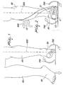
- the orthosis structure comprises a sole-piece 2 on which a foot 50 rests.
- the sole-piece 2 is modelled so as to reproduce a portion of the sole of the foot 50 and, in particular, so as to support the forefoot.
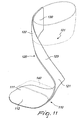
- the sole-piece has a flexible structure, which, during the walking movement, allows an elastic return of the force applied to flex it. This feature provides the orthosis structure 1 with a dynamic characteristic, which allows a more gradual transfer between the putting-down phase and the pushing-off phase, facilitating the forward movement.
- the sole-piece 2 has an anatomical cushioning insole (not shown in the accompanying figures), which is made of breathable material and designed so as to support the foot 50 at the physiologically correct points.
- the orthosis structure 1 comprises medial/lateral gripping means 10 associated with the sole-piece 2 and that can be engaged respectively with the medial zone, or lateral zone, of the leg 60 with which the foot 50 is articulated.
- a special feature of the medial/lateral gripping means 10 consists in the fact that the point where they are joined to the sole-piece 2, which corresponds essentially to the point where the torsional thrust 700 exerted by the foot 50 is applied, and their portion which can be engaged with the medial zone or lateral zone of the leg 60, which corresponds essentially to the point of application of the reaction of the constraint 800, are situated on opposite sides to each other relative to the longitudinal axis 600 of the leg 60.
- the orthosis structure 1 is designed to counteract the problem of varus-supination of the foot, also known as inversion, which is particularly frequent in patients affected by spasticity of the lower limbs.
- the medial/lateral gripping means 10 essentially comprises a shaped lever 11 which is formed with the lateral - or outer - portion of the sole-piece 2 and is engaged with the medial - or inner - zone of the leg 60.
- the sole-piece 2 is structured so as to engage with the part of the sole of the foot 50 corresponding to the forefoot and to the side (o lateral?) portion of the midfoot. These zones in fact have a fundamental role in opposing inversion of the foot 50 and supporting the latter.
- the shaped lever 11, together with the sole-piece 2 is made of materials which make it at the same time lighter, very rigid and stronger, such as carbon fibre or Kevlar, and owing to its characteristics it is able to oppose actively the inversion thrust exerted by the foot 50, transmitting it rigidly to the medial zone of the leg 60.
- the inversion thrust of the foot 50 would in fact tend to rotate the shaped lever 11 in the medio-lateral direction, but the medial zone of the leg 60 provides a physical constraint opposing this rotation.
- the sole-piece 2 is also counteracting the tendency of the medial portion of the foot to raise. Such tendency is counteracted by a restrain means associated with the sole-piece and preferably constituted by a strap 21 removably associated with the sole-piece 2.
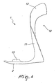
- the shaped lever 11 extends from the sole-piece 2 substantially along the portion associated with the midfoot, and extends so as to pass over the front pre-tibial zone of the leg 60, without necessarily making contact therewith.
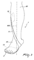
- the shaped lever 11 terminates in a plate 12, which allows it to rest against the medial zone of the leg 60.
- the length of the shaped lever 11 may be adjusted according to specific requirements.
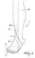
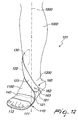
- the length of the shaped lever 11 may vary from a minimum length, where the plate 12 rests against the medial zone of the leg 60 just above the tibial malleolus, as substantially illustrated in Figure 8 , to a maximum length, where the plate 12 rests against the medial zone of the leg 60 just below the knee, as substantially illustrated in the Figures 2 to 7 .
- the shaped lever 11 is preferably inclined forwards at an angle variable substantially between 5° and 15° relative to the perpendicular of the sole-piece 2, in order to counteract hyperextension of the knee during the stance phase.
- the shaped lever 11 is also provided with an anatomical padding (not shown in the accompanying figures) which lines it internally, improving the comfort during use.
- This padding is significantly thinner in the pre-tibial region of the leg 60, so as to prevent contact thereof with the shaped lever 11.
- the rigidity of the shaped lever 11 may be increased by means of a rigid core (not visible in the figures) preferably consisting of a metallic insert, which is suitably modelled and incorporated in the structure of the shaped lever 11 so as to engage inside the sole-piece 2.
- the plate 12 may be supplemented with an adjustable band 20, which embraces the leg 60.
- a flange 13 projects from the medial portion of the sole-piece 2.
- the flange 13 has the end of the strap 21 removably joined thereto.
- the strap 21 crosses over the dorsal portion of the foot 50 and has an opposite end removably joined to the shaped lever 11, at the point where it is joined to the sole-piece 2, or in a higher position on the lever itself.
- the orthosis structure 1 may be completed by a stabilization appendage (not shown in the figures), which extends from the sole-piece 2 towards the hindfoot.
- the function of the stabilization appendage is that of counteracting extrarotation of the foot 50 during the putting-down phase.
- the orthosis structure according to the invention may also be used to counteract valgus-pronation of the foot, also known as eversion, even though this problem is rarer from a clinical point of view.
- the orthosis structure has a shaped lever, which forms the medial/lateral gripping means, integral with the medial - or inner - portion of the sole-piece 2 and engaged with the lateral - or outer - zone of the leg 60.
- the shaped lever which is now designed to transmit rigidly the eversion thrust exerted by the foot 50 to the lateral zone of the leg 60 which acts as a constraint, extends from the sole-piece 2 substantially in the zone corresponding to the midfoot, and extends so as to pass over the front region of the leg 60.
- the shaped lever terminates in a plate, which allows it to rest against the side zone of the leg 60.
- the flange extends from the side portion of the sole-piece 2.
- the orthosis structure 1 is fitted by inserting the sole-piece 2 inside a shoe and resting the sole of the foot 50 on top of it.
- the shaped lever 11 is arranged so as to pass over the tibial zone of the leg 60, while the plate 12 is rested against it in the medial or lateral zone thereof.
- Such construction physically provides a constraint which opposes the rotational movements induced by inversion of the foot 50.
- the strap 21 is fastened as well as the adjustable band 20, if present.
- an orthosis structure is globally designated by the reference numeral 101.
- the orthosis structure 101 comprises a sole-piece 110 which can be associated with the sole of a foot 1100, which is articulated with a leg 1000.
- the lateral - or outer - portion of the sole-piece 110 is joined to medial gripping members, which can be engaged with the medial - or inner - zone of the leg 1000.
- the medial gripping members, as well as the rest of the sole-piece 110, are suitably made of a composite material of the polymer type. Consequently, they are composed of a matrix which gives them their form and which contains a reinforcement consisting of carbon fibres, Kevlar or other synthetic polymer fibres.
- the medial gripping members mainly take the form of a shaped lever 120, which is designed to transmit rigidly to the medial zone of the leg 1000 the supinatory thrust exerted by the foot 1100 on the sole-piece 110.
- a strap 140 which will be described further on, has the important function of bearing the other half of the supinatory thrust exerted by the foot.
- the terminal portion 121 of the shaped lever 120 is joined to the side portion of the sole-piece 110, while a contact portion 130, which can be engaged with the medial zone of the leg 1000, is formed on its apical portion 122.
- the point where the shaped lever 120 is joined to the sole-piece 110, which corresponds essentially to the point of application of the supinatory thrust 2000 exerted by the foot 1100, and the contact portion 130, which corresponds essentially to the point of application of the reaction of the constraint 3000, are situated on opposite sides to each other relative to the longitudinal axis 1500 of the leg 1000.
- the shaped lever 120 extends from the sole-piece 110, substantially along the portion associated with the midfoot, and extends so as to pass over the front zone of the leg 1000, without necessarily making contact therewith.
- the shaped lever 120 rests against the medial zone of the leg 1000 with the contact portion 130.
- the shaped lever 120 is inclined forwards, in the antero-posterior plane, at an angle variable substantially between 5° and 15° relative to the perpendicular of the sole-piece 110. It is thus possible to counteract hyperextension of the knee during the putting-down phase.
- the shaped lever 120 is also provided with anatomical padding (not shown in the accompanying figures) which lines it internally, improving the comfort during use.
- the sole-piece 110 comprises a rigid portion 111 integral with the medial gripping members.
- the rigid portion 111 can be engaged with the anterior part of the metatarsal zone of the foot 1100 so as to provide a rigid constraint opposing the supinatory thrust exerted by the latter.
- the rigid portion 111 is joined laterally to the terminal portion 121 of the shaped lever 120 and is modelled so as to engage with the metatarsal zone, leaving the hindfoot completely free.
- a flexible portion 112 is joined as one piece at the front of the rigid portion 111 and is able to return elastically part of the flexural force during the terminal phase of putting down of the foot 1100, allowing, during walking, a more gradual transfer between the putting-down phase, the pushing-off phase and the toe-off phase.
- the flexible portion 112 can be engaged with the zone of the foot 1100 substantially delimited by the phalanxes and by the distal metatarsal ends.
- the different elastic response between the two portions described may be advantageously obtained by choosing and suitably combining the matrix and the fibres, which form the composite material from which the orthosis structure 101 is made.
- the elasticity of the orthosis structure 101 in the antero-posterior plane may be predefined or may be adjustable, namely may be adjusted to the requirements, which may vary over time, of the neurological or orthopaedic patient, and to the lever forces to be opposed.
- the orthosis structure 101 will be provided with adjustable stiffening means (not shown in the accompanying figures) associated with the points where there is greatest flexing of the shaped lever 120.
- the adjustable stiffening means may comprise, for example, a rigid slider, which can be associated horizontally with the central portion 123 of the shaped lever 120.
- the foot 1100 is constrained to the sole-piece 110 by restrain means, which extends from the medial portion of the latter, embraces the dorsal portion of the foot 1100 and reaches the lateral portion of the sole-piece 110.
- the restrain means takes the form of a first strap 140.
- the first strap 140 can be associated, in a removable manner, with the single rigid portion 111 only, or with the flexible portion 112 too, so as to engage transversely with the midfoot and forefoot, retaining if necessary also the toes of the foot.
- the dynamic response of the medial gripping members may be increased by controlled-movement articulation means which allow a limited and reversible displacement in the antero-posterior plane of said gripping members with respect to the sole-piece 110 so as to favour dorsal flexion of the foot and flexing of the knee.
- the articulation means also ensure the elastic return into a predefined adjustable initial position when the cause of the stress ceases.
- the articulation means comprises a first resilient hinge 160 formed directly on the shaped lever 120, substantially along the portion which can be associated with the ankle 1200 of the leg 1000 or if necessary consisting of a suitable separate device incorporated in the said shaped lever 120 during manufacture.
- the resilient hinge 160 is essentially composed of a first pair of arms 161 and 162 which are pivotally connected together by means of a joining member 163 and are respectively connected to the shaped lever 120 and to the sole-piece 110 so as be more or less parallel to the antero-posterior plane. These arms are constrained by a first spring (not shown in the accompanying figures) which limits the relative movement thereof and tends to bring them back automatically into the initial condition when the stress causing the displacement ceases.
- the two arms 161 and 162 are substantially flat and may have substantially discshaped ends which are arranged on top of each other with the possibility of rotation.
- the retaining means also comprises an adjustable band 150, which is preferably made, like the first strap 140, of multi-layered fabric, which ensures stability and breathability.
- the adjustable band 150 is removably associated with the contact portion 130 alone or with the entire shaped lever 120 so as to engage with the zone of the leg 1000 substantially delimited by the malleolus and by the apical portion of the said contact portion 130.
- the articulation means may consist of a second resilient hinge 120 formed directly on the shaped lever 120, substantially along the central portion 123, or consisting of a suitable separate device incorporated in the said shaped lever 120 during manufacture.
- the second resilient hinge comprises a second pair of substantially flat arms which are joined together so as to be slidable and are respectively connected to the terminal portion 121 and to the apical portion 122 of the shaped lever 120 so as to be substantially parallel to the frontal plane and transverse to the antero-posterior plane.
- These arms are constrained by a suitable restraining device consisting for example of a pawi associated with one of the two arms and a series of corresponding holes formed in the other arm.
- the restraining device is designed to limit the relative movement of the two arms of the second pair and bring them back automatically into the initial condition when the stress which caused the change in their relative position ceases.
- the rigidity of the first arm increases closer to the terminal portion 121 of the shaped lever 120
- the rigidity of the second arm is increased by a pair of guides, which slidably receive the first arm.
- the orthoses structure 1 achieves the maximum rigidity envisaged in the antero-posterior plane, while conversely, when the two arms move away from each other, the anteroposterior elasticity increases.
- the orthosis structure 101 is fitted by associating the sole-piece 110 with the sole of the foot 1100, fixing it with the first strap 140 and resting the contact portion 130 against the medial zone of the leg 1000, fixing it using the second strap 150.
- the foot 1100 exerts its supinatory thrust on the rigid portion 111 of the sole-piece 110, the latter, by means of the shaped lever 120, transmits it rigidly to the contact portion 130, which encounters a physical constraint in the medial zone of the leg 1000.
- the line embraces, without necessarily making contact, the frontal zone of the lowest portion of the leg 1000 and then makes contact with the medial surface of the same leg 1000, at least above the tibial malleolus, where the supinatory lever force is discharged, encountering a solid constraint.
- the strap 140 While the lateral side of the rigid plantar bears the downward rotational thrust of the lateral side of the forefoot, the strap 140 has the important function of bearing the other half, upward rotational thrust of the medial side of the forefoot.
- the flexible portion 112 allows a more gradual transfer from the putting-down phase to the pushing-off phase of the foot 1100.
- controlled-movement articulation means may also be used, allowing a limited and reversible displacement of the medial gripping members with respect to the sole-piece 110, increasing further the rigidity in the frontal plane and the elasticity in the antero-posterior plane so as to favour the correct dynamics of the walking movement.
- the structure according to the present invention is resilient on its sagittal plane, i.e. on the median longitudinal plane of the leg and foot, while being substantially stiff in its frontal, or transversal plane.
- Such constructive features may be achieved by suitably orienting the fibers and sheets that constitute the carbon fiber structure.
- the structure according to the present invention substantially lack a heel portion of the sole-piece, 2 or 110, and substantially lack any rear and inner portion of the shaped lever 11, 120 extending beyond the plate 12, or contact portion 130.
- the shaped lever 11, 120 ends at the medial side of the calf without extending back in the posterior side of the calf, because there is no need of tightly binding the calf in the sagittal plane.
- the lack of a back and inner portion of the shaped lever is extremely advantageous and makes the orthosis structure according to the present invention very easy to wear.
- the orthosis structure according to the invention is particularly effective in counteracting the deformities in valgus-pronation or the spasticity in varus-supination of the foot, ensuring a good stability of the ankle and the foot and at the same time a more dynamic and functional walking movement.
- the orthosis structure according to the invention controls the foot drop during the swinging phase and ensures a more stable walking movement.
- the orthosis structure according to the invention is lightweight and comfortable and also aesthetically pleasing.
- the orthosis structure according to the invention is also designed to oppose the supination movement of the foot.
- the orthosis structure according to the invention is able to provide a rigid constraint opposing the supinatory thrust and to support the foot, offering maximum rigidity in the frontal plane, as well as favour the correct dynamics of the gait, owing to its elasticity in the sagittal plane.
- the orthosis structure according to the invention helps preventing the hyperextension of the knee and is useful for neurological patients, in order to counteract the unwanted supinatory movement, which is frequently observed as a pathological reflex in pareses due to central neurological lesion, as well as in orthopaedic patients as a means for preventing recurrent twisting of the ankle and instep injuries.
- orthosis structure according to the invention may be used with all commercially available footwear, without having to modify the footwear after purchase.
Landscapes
- Health & Medical Sciences (AREA)
- Nursing (AREA)
- Orthopedic Medicine & Surgery (AREA)
- Engineering & Computer Science (AREA)
- Biomedical Technology (AREA)
- Heart & Thoracic Surgery (AREA)
- Vascular Medicine (AREA)
- Life Sciences & Earth Sciences (AREA)
- Animal Behavior & Ethology (AREA)
- General Health & Medical Sciences (AREA)
- Public Health (AREA)
- Veterinary Medicine (AREA)
- Orthopedics, Nursing, And Contraception (AREA)
- Prostheses (AREA)
Priority Applications (1)
| Application Number | Priority Date | Filing Date | Title |
|---|---|---|---|
| PL09746301T PL2242460T3 (pl) | 2008-05-15 | 2009-05-14 | Orteza stawu skokowego do przeciwdziałania stopie szpotawej lub płasko-koślawej |
Applications Claiming Priority (3)
| Application Number | Priority Date | Filing Date | Title |
|---|---|---|---|
| ITVI20080110 ITVI20080110A1 (it) | 2008-05-15 | 2008-05-15 | Struttura di ortesi, particolarmente per caviglia-piede. |
| IT000087A ITVI20090087A1 (it) | 2009-04-22 | 2009-04-22 | Struttura di ortesi perfezionata, particolarmente per caviglia-piede. |
| PCT/IT2009/000214 WO2009139019A1 (en) | 2008-05-15 | 2009-05-14 | Ankle foot orthosis for counteracting the supination/pronation of the foot |
Publications (2)
| Publication Number | Publication Date |
|---|---|
| EP2242460A1 EP2242460A1 (en) | 2010-10-27 |
| EP2242460B1 true EP2242460B1 (en) | 2011-11-09 |
Family
ID=41076842
Family Applications (1)
| Application Number | Title | Priority Date | Filing Date |
|---|---|---|---|
| EP09746301A Active EP2242460B1 (en) | 2008-05-15 | 2009-05-14 | Ankle foot orthosis for counteracting the supination/pronation of the foot |
Country Status (4)
| Country | Link |
|---|---|
| EP (1) | EP2242460B1 (pl) |
| AT (1) | ATE532486T1 (pl) |
| PL (1) | PL2242460T3 (pl) |
| WO (1) | WO2009139019A1 (pl) |
Cited By (1)
| Publication number | Priority date | Publication date | Assignee | Title |
|---|---|---|---|---|
| RU176962U1 (ru) * | 2017-08-29 | 2018-02-02 | Общество с ограниченной ответственностью "Санкт-Петербургская ортопедическая компания" (ООО "СП") | Комплект детской ортопедической обуви для поддержания пролеченной врожденной косолапости |
Families Citing this family (7)
| Publication number | Priority date | Publication date | Assignee | Title |
|---|---|---|---|---|
| DE202014104234U1 (de) * | 2014-09-08 | 2015-12-09 | Frank Friedrich Gröhninger | Orthese und System zur Stützung des Fußes |
| SI25321B (sl) | 2016-12-27 | 2026-01-30 | aNImaKe d.o.o. | Gleženjska ortoza |
| US11872151B2 (en) | 2017-05-12 | 2024-01-16 | Ast Design, Llc | Method of manufacturing an ankle foot orthosis |
| US11484426B2 (en) | 2017-05-12 | 2022-11-01 | Ast Design, Llc | Foot ankle orthoses |
| US11857448B2 (en) | 2018-02-02 | 2024-01-02 | Otto Bock Healthcare Lp | Methods and apparatus for treating osteoarthritis of the knee |
| KR102132988B1 (ko) * | 2018-06-15 | 2020-07-10 | 호서대학교 산학협력단 | 탄력중립발목보조기 |
| EP4333778B1 (en) | 2021-06-30 | 2026-04-22 | Thorwear, Inc. | Ankle foot orthoses and method of manufacturing |
Family Cites Families (8)
| Publication number | Priority date | Publication date | Assignee | Title |
|---|---|---|---|---|
| US3680549A (en) * | 1970-05-08 | 1972-08-01 | Research Corp | Spiral orthosis for the lower extremity |
| US5219324A (en) * | 1992-03-12 | 1993-06-15 | Charles Hall | Anterior dorsal ankle foot orthoses |
| DE9205791U1 (de) | 1992-04-30 | 1992-07-02 | Otto Bock Orthopädische Industrie Besitz- und Verwaltungs-Kommanditgesellschaft, 3408 Duderstadt | Sprunggelenkorthese |
| US5897515A (en) * | 1997-02-05 | 1999-04-27 | Light Weight Support Ab | Ankle-foot orthosis |
| SE0101341D0 (sv) | 2001-04-18 | 2001-04-18 | Camp Scandinavia Ab | Ankle-foot orthosis |
| EP1562526B1 (en) | 2002-11-07 | 2007-08-15 | Ossur HF | Ankle-foot orthosis |
| US20070038169A1 (en) | 2003-09-22 | 2007-02-15 | Dankmeyer, Inc. | Lower leg orthosis |
| US7458950B1 (en) | 2004-07-02 | 2008-12-02 | Michael Ivany | Ankle foot orthosis |
-
2009
- 2009-05-14 AT AT09746301T patent/ATE532486T1/de active
- 2009-05-14 PL PL09746301T patent/PL2242460T3/pl unknown
- 2009-05-14 WO PCT/IT2009/000214 patent/WO2009139019A1/en not_active Ceased
- 2009-05-14 EP EP09746301A patent/EP2242460B1/en active Active
Cited By (1)
| Publication number | Priority date | Publication date | Assignee | Title |
|---|---|---|---|---|
| RU176962U1 (ru) * | 2017-08-29 | 2018-02-02 | Общество с ограниченной ответственностью "Санкт-Петербургская ортопедическая компания" (ООО "СП") | Комплект детской ортопедической обуви для поддержания пролеченной врожденной косолапости |
Also Published As
| Publication number | Publication date |
|---|---|
| ATE532486T1 (de) | 2011-11-15 |
| PL2242460T3 (pl) | 2012-04-30 |
| EP2242460A1 (en) | 2010-10-27 |
| WO2009139019A1 (en) | 2009-11-19 |
Similar Documents
| Publication | Publication Date | Title |
|---|---|---|
| EP2242460B1 (en) | Ankle foot orthosis for counteracting the supination/pronation of the foot | |
| US20230398011A1 (en) | Orthotic system | |
| EP2110104B1 (en) | Night splint with digital dorsiflexion | |
| US8529484B2 (en) | Orthotic foot brace | |
| US7785283B1 (en) | Ankle stabilizing device | |
| US9192502B2 (en) | Ankle-foot orthotic | |
| KR20170085965A (ko) | 족부의 3차원 운동 제어 및 족저 압력의 분산을 위한 디바이스 | |
| US8221341B1 (en) | Adjustable response ankle foot orthotic | |
| US10105252B2 (en) | Orthotic device | |
| US20170252197A1 (en) | Ankle-Foot Orthosis | |
| DK2533734T3 (en) | ORTHOPEDIC FOOTWEAR TO REMOVE DROP FOOT SYMPTOMS | |
| US9452077B2 (en) | Foot and ankle orthoses that enable natural movement of the foot | |
| WO2022185483A1 (ja) | 下垂足矯正用具 | |
| Philbin et al. | Orthotic and prosthetic devices in partial foot amputations | |
| US9622898B1 (en) | Ankle brace | |
| CA2692534C (en) | Orthotic foot brace | |
| JP2000254155A (ja) | 足矯正用てこ装置及びその使用方法 | |
| CN222983221U (zh) | 一种牵拉型膝踝足矫形器 | |
| CN212545843U (zh) | 一种踝足矫形鞋 | |
| TWI865514B (zh) | 下肢矯正器 | |
| JP7078993B2 (ja) | 短下肢装具 | |
| EP1634553A1 (en) | Dorsal brace for ankle joint | |
| Holowka et al. | Bracing and orthotics | |
| GB2568713A (en) | A device for an item of footwear |
Legal Events
| Date | Code | Title | Description |
|---|---|---|---|
| PUAI | Public reference made under article 153(3) epc to a published international application that has entered the european phase |
Free format text: ORIGINAL CODE: 0009012 |
|
| 17P | Request for examination filed |
Effective date: 20100730 |
|
| AK | Designated contracting states |
Kind code of ref document: A1 Designated state(s): AT BE BG CH CY CZ DE DK EE ES FI FR GB GR HR HU IE IS IT LI LT LU LV MC MK MT NL NO PL PT RO SE SI SK TR |
|
| AX | Request for extension of the european patent |
Extension state: AL BA RS |
|
| 17Q | First examination report despatched |
Effective date: 20101119 |
|
| GRAP | Despatch of communication of intention to grant a patent |
Free format text: ORIGINAL CODE: EPIDOSNIGR1 |
|
| DAX | Request for extension of the european patent (deleted) | ||
| GRAS | Grant fee paid |
Free format text: ORIGINAL CODE: EPIDOSNIGR3 |
|
| GRAA | (expected) grant |
Free format text: ORIGINAL CODE: 0009210 |
|
| AK | Designated contracting states |
Kind code of ref document: B1 Designated state(s): AT BE BG CH CY CZ DE DK EE ES FI FR GB GR HR HU IE IS IT LI LT LU LV MC MK MT NL NO PL PT RO SE SI SK TR |
|
| REG | Reference to a national code |
Ref country code: GB Ref legal event code: FG4D |
|
| REG | Reference to a national code |
Ref country code: CH Ref legal event code: EP |
|
| REG | Reference to a national code |
Ref country code: IE Ref legal event code: FG4D |
|
| REG | Reference to a national code |
Ref country code: DE Ref legal event code: R096 Ref document number: 602009003633 Country of ref document: DE Effective date: 20120105 |
|
| REG | Reference to a national code |
Ref country code: NL Ref legal event code: T3 |
|
| REG | Reference to a national code |
Ref country code: SE Ref legal event code: TRGR |
|
| LTIE | Lt: invalidation of european patent or patent extension |
Effective date: 20111109 |
|
| PG25 | Lapsed in a contracting state [announced via postgrant information from national office to epo] |
Ref country code: NO Free format text: LAPSE BECAUSE OF FAILURE TO SUBMIT A TRANSLATION OF THE DESCRIPTION OR TO PAY THE FEE WITHIN THE PRESCRIBED TIME-LIMIT Effective date: 20120209 Ref country code: IS Free format text: LAPSE BECAUSE OF FAILURE TO SUBMIT A TRANSLATION OF THE DESCRIPTION OR TO PAY THE FEE WITHIN THE PRESCRIBED TIME-LIMIT Effective date: 20120309 Ref country code: LT Free format text: LAPSE BECAUSE OF FAILURE TO SUBMIT A TRANSLATION OF THE DESCRIPTION OR TO PAY THE FEE WITHIN THE PRESCRIBED TIME-LIMIT Effective date: 20111109 |
|
| REG | Reference to a national code |
Ref country code: PL Ref legal event code: T3 |
|
| PG25 | Lapsed in a contracting state [announced via postgrant information from national office to epo] |
Ref country code: GR Free format text: LAPSE BECAUSE OF FAILURE TO SUBMIT A TRANSLATION OF THE DESCRIPTION OR TO PAY THE FEE WITHIN THE PRESCRIBED TIME-LIMIT Effective date: 20120210 Ref country code: SI Free format text: LAPSE BECAUSE OF FAILURE TO SUBMIT A TRANSLATION OF THE DESCRIPTION OR TO PAY THE FEE WITHIN THE PRESCRIBED TIME-LIMIT Effective date: 20111109 Ref country code: PT Free format text: LAPSE BECAUSE OF FAILURE TO SUBMIT A TRANSLATION OF THE DESCRIPTION OR TO PAY THE FEE WITHIN THE PRESCRIBED TIME-LIMIT Effective date: 20120309 Ref country code: LV Free format text: LAPSE BECAUSE OF FAILURE TO SUBMIT A TRANSLATION OF THE DESCRIPTION OR TO PAY THE FEE WITHIN THE PRESCRIBED TIME-LIMIT Effective date: 20111109 Ref country code: HR Free format text: LAPSE BECAUSE OF FAILURE TO SUBMIT A TRANSLATION OF THE DESCRIPTION OR TO PAY THE FEE WITHIN THE PRESCRIBED TIME-LIMIT Effective date: 20111109 Ref country code: BE Free format text: LAPSE BECAUSE OF FAILURE TO SUBMIT A TRANSLATION OF THE DESCRIPTION OR TO PAY THE FEE WITHIN THE PRESCRIBED TIME-LIMIT Effective date: 20111109 |
|
| PG25 | Lapsed in a contracting state [announced via postgrant information from national office to epo] |
Ref country code: CY Free format text: LAPSE BECAUSE OF FAILURE TO SUBMIT A TRANSLATION OF THE DESCRIPTION OR TO PAY THE FEE WITHIN THE PRESCRIBED TIME-LIMIT Effective date: 20111109 |
|
| PG25 | Lapsed in a contracting state [announced via postgrant information from national office to epo] |
Ref country code: DK Free format text: LAPSE BECAUSE OF FAILURE TO SUBMIT A TRANSLATION OF THE DESCRIPTION OR TO PAY THE FEE WITHIN THE PRESCRIBED TIME-LIMIT Effective date: 20111109 Ref country code: BG Free format text: LAPSE BECAUSE OF FAILURE TO SUBMIT A TRANSLATION OF THE DESCRIPTION OR TO PAY THE FEE WITHIN THE PRESCRIBED TIME-LIMIT Effective date: 20120209 Ref country code: EE Free format text: LAPSE BECAUSE OF FAILURE TO SUBMIT A TRANSLATION OF THE DESCRIPTION OR TO PAY THE FEE WITHIN THE PRESCRIBED TIME-LIMIT Effective date: 20111109 Ref country code: SK Free format text: LAPSE BECAUSE OF FAILURE TO SUBMIT A TRANSLATION OF THE DESCRIPTION OR TO PAY THE FEE WITHIN THE PRESCRIBED TIME-LIMIT Effective date: 20111109 |
|
| PG25 | Lapsed in a contracting state [announced via postgrant information from national office to epo] |
Ref country code: RO Free format text: LAPSE BECAUSE OF FAILURE TO SUBMIT A TRANSLATION OF THE DESCRIPTION OR TO PAY THE FEE WITHIN THE PRESCRIBED TIME-LIMIT Effective date: 20111109 |
|
| PLBE | No opposition filed within time limit |
Free format text: ORIGINAL CODE: 0009261 |
|
| STAA | Information on the status of an ep patent application or granted ep patent |
Free format text: STATUS: NO OPPOSITION FILED WITHIN TIME LIMIT |
|
| REG | Reference to a national code |
Ref country code: AT Ref legal event code: MK05 Ref document number: 532486 Country of ref document: AT Kind code of ref document: T Effective date: 20111109 |
|
| 26N | No opposition filed |
Effective date: 20120810 |
|
| REG | Reference to a national code |
Ref country code: DE Ref legal event code: R097 Ref document number: 602009003633 Country of ref document: DE Effective date: 20120810 |
|
| PG25 | Lapsed in a contracting state [announced via postgrant information from national office to epo] |
Ref country code: MC Free format text: LAPSE BECAUSE OF NON-PAYMENT OF DUE FEES Effective date: 20120531 |
|
| PG25 | Lapsed in a contracting state [announced via postgrant information from national office to epo] |
Ref country code: AT Free format text: LAPSE BECAUSE OF FAILURE TO SUBMIT A TRANSLATION OF THE DESCRIPTION OR TO PAY THE FEE WITHIN THE PRESCRIBED TIME-LIMIT Effective date: 20111109 |
|
| REG | Reference to a national code |
Ref country code: IE Ref legal event code: MM4A |
|
| PG25 | Lapsed in a contracting state [announced via postgrant information from national office to epo] |
Ref country code: MK Free format text: LAPSE BECAUSE OF FAILURE TO SUBMIT A TRANSLATION OF THE DESCRIPTION OR TO PAY THE FEE WITHIN THE PRESCRIBED TIME-LIMIT Effective date: 20111109 |
|
| PG25 | Lapsed in a contracting state [announced via postgrant information from national office to epo] |
Ref country code: IE Free format text: LAPSE BECAUSE OF NON-PAYMENT OF DUE FEES Effective date: 20120514 Ref country code: ES Free format text: LAPSE BECAUSE OF FAILURE TO SUBMIT A TRANSLATION OF THE DESCRIPTION OR TO PAY THE FEE WITHIN THE PRESCRIBED TIME-LIMIT Effective date: 20120220 |
|
| REG | Reference to a national code |
Ref country code: DE Ref legal event code: R082 Ref document number: 602009003633 Country of ref document: DE |
|
| PG25 | Lapsed in a contracting state [announced via postgrant information from national office to epo] |
Ref country code: FI Free format text: LAPSE BECAUSE OF FAILURE TO SUBMIT A TRANSLATION OF THE DESCRIPTION OR TO PAY THE FEE WITHIN THE PRESCRIBED TIME-LIMIT Effective date: 20111109 |
|
| PG25 | Lapsed in a contracting state [announced via postgrant information from national office to epo] |
Ref country code: MT Free format text: LAPSE BECAUSE OF FAILURE TO SUBMIT A TRANSLATION OF THE DESCRIPTION OR TO PAY THE FEE WITHIN THE PRESCRIBED TIME-LIMIT Effective date: 20111109 |
|
| REG | Reference to a national code |
Ref country code: CH Ref legal event code: PL |
|
| PG25 | Lapsed in a contracting state [announced via postgrant information from national office to epo] |
Ref country code: CH Free format text: LAPSE BECAUSE OF NON-PAYMENT OF DUE FEES Effective date: 20130531 Ref country code: LI Free format text: LAPSE BECAUSE OF NON-PAYMENT OF DUE FEES Effective date: 20130531 |
|
| PG25 | Lapsed in a contracting state [announced via postgrant information from national office to epo] |
Ref country code: LU Free format text: LAPSE BECAUSE OF NON-PAYMENT OF DUE FEES Effective date: 20120514 |
|
| PG25 | Lapsed in a contracting state [announced via postgrant information from national office to epo] |
Ref country code: HU Free format text: LAPSE BECAUSE OF FAILURE TO SUBMIT A TRANSLATION OF THE DESCRIPTION OR TO PAY THE FEE WITHIN THE PRESCRIBED TIME-LIMIT Effective date: 20090514 |
|
| REG | Reference to a national code |
Ref country code: FR Ref legal event code: PLFP Year of fee payment: 8 |
|
| REG | Reference to a national code |
Ref country code: FR Ref legal event code: PLFP Year of fee payment: 9 |
|
| REG | Reference to a national code |
Ref country code: FR Ref legal event code: PLFP Year of fee payment: 10 |
|
| PGFP | Annual fee paid to national office [announced via postgrant information from national office to epo] |
Ref country code: NL Payment date: 20220526 Year of fee payment: 14 |
|
| PGFP | Annual fee paid to national office [announced via postgrant information from national office to epo] |
Ref country code: SE Payment date: 20220523 Year of fee payment: 14 Ref country code: CZ Payment date: 20220513 Year of fee payment: 14 |
|
| PGFP | Annual fee paid to national office [announced via postgrant information from national office to epo] |
Ref country code: TR Payment date: 20220505 Year of fee payment: 14 Ref country code: PL Payment date: 20220504 Year of fee payment: 14 |
|
| PGFP | Annual fee paid to national office [announced via postgrant information from national office to epo] |
Ref country code: FR Payment date: 20230523 Year of fee payment: 15 Ref country code: DE Payment date: 20230530 Year of fee payment: 15 |
|
| PGFP | Annual fee paid to national office [announced via postgrant information from national office to epo] |
Ref country code: GB Payment date: 20230523 Year of fee payment: 15 |
|
| REG | Reference to a national code |
Ref country code: SE Ref legal event code: EUG |
|
| REG | Reference to a national code |
Ref country code: NL Ref legal event code: MM Effective date: 20230601 |
|
| PG25 | Lapsed in a contracting state [announced via postgrant information from national office to epo] |
Ref country code: SE Free format text: LAPSE BECAUSE OF NON-PAYMENT OF DUE FEES Effective date: 20230515 Ref country code: CZ Free format text: LAPSE BECAUSE OF NON-PAYMENT OF DUE FEES Effective date: 20230514 |
|
| PG25 | Lapsed in a contracting state [announced via postgrant information from national office to epo] |
Ref country code: NL Free format text: LAPSE BECAUSE OF NON-PAYMENT OF DUE FEES Effective date: 20230601 |
|
| PGFP | Annual fee paid to national office [announced via postgrant information from national office to epo] |
Ref country code: IT Payment date: 20240521 Year of fee payment: 16 |
|
| PG25 | Lapsed in a contracting state [announced via postgrant information from national office to epo] |
Ref country code: PL Free format text: LAPSE BECAUSE OF NON-PAYMENT OF DUE FEES Effective date: 20230514 |
|
| PG25 | Lapsed in a contracting state [announced via postgrant information from national office to epo] |
Ref country code: PL Free format text: LAPSE BECAUSE OF NON-PAYMENT OF DUE FEES Effective date: 20230514 |
|
| REG | Reference to a national code |
Ref country code: DE Ref legal event code: R119 Ref document number: 602009003633 Country of ref document: DE |
|
| GBPC | Gb: european patent ceased through non-payment of renewal fee |
Effective date: 20240514 |
|
| PG25 | Lapsed in a contracting state [announced via postgrant information from national office to epo] |
Ref country code: DE Free format text: LAPSE BECAUSE OF NON-PAYMENT OF DUE FEES Effective date: 20241203 |
|
| PG25 | Lapsed in a contracting state [announced via postgrant information from national office to epo] |
Ref country code: FR Free format text: LAPSE BECAUSE OF NON-PAYMENT OF DUE FEES Effective date: 20240531 |
|
| PG25 | Lapsed in a contracting state [announced via postgrant information from national office to epo] |
Ref country code: GB Free format text: LAPSE BECAUSE OF NON-PAYMENT OF DUE FEES Effective date: 20240514 |
|
| PG25 | Lapsed in a contracting state [announced via postgrant information from national office to epo] |
Ref country code: IT Free format text: LAPSE BECAUSE OF NON-PAYMENT OF DUE FEES Effective date: 20250514 |