EP2242423B1 - Analysing impedance measurements - Google Patents
Analysing impedance measurements Download PDFInfo
- Publication number
- EP2242423B1 EP2242423B1 EP09710912.8A EP09710912A EP2242423B1 EP 2242423 B1 EP2242423 B1 EP 2242423B1 EP 09710912 A EP09710912 A EP 09710912A EP 2242423 B1 EP2242423 B1 EP 2242423B1
- Authority
- EP
- European Patent Office
- Prior art keywords
- subject
- impedance
- indicator
- processing system
- index
- Prior art date
- Legal status (The legal status is an assumption and is not a legal conclusion. Google has not performed a legal analysis and makes no representation as to the accuracy of the status listed.)
- Not-in-force
Links
- 238000002847 impedance measurement Methods 0.000 title claims description 52
- 238000000034 method Methods 0.000 claims description 97
- 201000002282 venous insufficiency Diseases 0.000 claims description 95
- 238000012545 processing Methods 0.000 claims description 91
- 238000005259 measurement Methods 0.000 claims description 60
- 210000003722 extracellular fluid Anatomy 0.000 claims description 31
- 230000008859 change Effects 0.000 claims description 26
- 239000012530 fluid Substances 0.000 claims description 13
- 210000002977 intracellular fluid Anatomy 0.000 claims description 12
- 238000002203 pretreatment Methods 0.000 claims description 6
- 230000004044 response Effects 0.000 claims description 4
- 210000002414 leg Anatomy 0.000 description 36
- 206010030113 Oedema Diseases 0.000 description 33
- 230000008569 process Effects 0.000 description 31
- 238000011176 pooling Methods 0.000 description 29
- 210000004369 blood Anatomy 0.000 description 25
- 239000008280 blood Substances 0.000 description 25
- 238000004458 analytical method Methods 0.000 description 22
- 206010025282 Lymphoedema Diseases 0.000 description 19
- 208000002502 lymphedema Diseases 0.000 description 19
- 210000003414 extremity Anatomy 0.000 description 13
- 230000015654 memory Effects 0.000 description 11
- 230000000694 effects Effects 0.000 description 9
- 230000003834 intracellular effect Effects 0.000 description 7
- 210000001519 tissue Anatomy 0.000 description 7
- 230000000052 comparative effect Effects 0.000 description 6
- 210000003462 vein Anatomy 0.000 description 6
- 230000009467 reduction Effects 0.000 description 5
- 238000000611 regression analysis Methods 0.000 description 5
- 238000004611 spectroscopical analysis Methods 0.000 description 5
- 210000003423 ankle Anatomy 0.000 description 4
- 238000011871 bio-impedance analysis Methods 0.000 description 4
- 244000309466 calf Species 0.000 description 4
- 238000011835 investigation Methods 0.000 description 4
- 239000000203 mixture Substances 0.000 description 4
- 239000003990 capacitor Substances 0.000 description 3
- 230000008878 coupling Effects 0.000 description 3
- 238000010168 coupling process Methods 0.000 description 3
- 238000005859 coupling reaction Methods 0.000 description 3
- 238000001514 detection method Methods 0.000 description 3
- 238000010586 diagram Methods 0.000 description 3
- 206010051055 Deep vein thrombosis Diseases 0.000 description 2
- 241001465754 Metazoa Species 0.000 description 2
- 206010047249 Venous thrombosis Diseases 0.000 description 2
- 238000002679 ablation Methods 0.000 description 2
- 238000004364 calculation method Methods 0.000 description 2
- 210000000170 cell membrane Anatomy 0.000 description 2
- 208000037998 chronic venous disease Diseases 0.000 description 2
- 210000002683 foot Anatomy 0.000 description 2
- 230000006870 function Effects 0.000 description 2
- 230000004217 heart function Effects 0.000 description 2
- 238000010234 longitudinal analysis Methods 0.000 description 2
- 230000001926 lymphatic effect Effects 0.000 description 2
- 238000012986 modification Methods 0.000 description 2
- 230000004048 modification Effects 0.000 description 2
- 210000003205 muscle Anatomy 0.000 description 2
- 230000001144 postural effect Effects 0.000 description 2
- 230000003068 static effect Effects 0.000 description 2
- 210000000115 thoracic cavity Anatomy 0.000 description 2
- 241000777300 Congiopodidae Species 0.000 description 1
- 241000288906 Primates Species 0.000 description 1
- 206010042674 Swelling Diseases 0.000 description 1
- 206010046996 Varicose vein Diseases 0.000 description 1
- 230000002159 abnormal effect Effects 0.000 description 1
- 230000009471 action Effects 0.000 description 1
- 230000004913 activation Effects 0.000 description 1
- 210000004712 air sac Anatomy 0.000 description 1
- 210000003484 anatomy Anatomy 0.000 description 1
- 238000010420 art technique Methods 0.000 description 1
- 210000001142 back Anatomy 0.000 description 1
- 230000006399 behavior Effects 0.000 description 1
- 230000008901 benefit Effects 0.000 description 1
- 239000000090 biomarker Substances 0.000 description 1
- 230000017531 blood circulation Effects 0.000 description 1
- 230000036765 blood level Effects 0.000 description 1
- 210000001124 body fluid Anatomy 0.000 description 1
- 239000010839 body fluid Substances 0.000 description 1
- 230000000747 cardiac effect Effects 0.000 description 1
- 201000002816 chronic venous insufficiency Diseases 0.000 description 1
- 230000004087 circulation Effects 0.000 description 1
- 238000004891 communication Methods 0.000 description 1
- 239000004020 conductor Substances 0.000 description 1
- 230000001419 dependent effect Effects 0.000 description 1
- 229940079593 drug Drugs 0.000 description 1
- 239000003814 drug Substances 0.000 description 1
- 238000004070 electrodeposition Methods 0.000 description 1
- 230000002708 enhancing effect Effects 0.000 description 1
- 230000007613 environmental effect Effects 0.000 description 1
- 210000003743 erythrocyte Anatomy 0.000 description 1
- 238000013213 extrapolation Methods 0.000 description 1
- 238000001914 filtration Methods 0.000 description 1
- PCHJSUWPFVWCPO-UHFFFAOYSA-N gold Chemical compound [Au] PCHJSUWPFVWCPO-UHFFFAOYSA-N 0.000 description 1
- 230000005484 gravity Effects 0.000 description 1
- 230000001435 haemodynamic effect Effects 0.000 description 1
- 230000036541 health Effects 0.000 description 1
- 230000003862 health status Effects 0.000 description 1
- 230000000004 hemodynamic effect Effects 0.000 description 1
- 238000002489 impedance cardiography Methods 0.000 description 1
- 230000001939 inductive effect Effects 0.000 description 1
- 239000012212 insulator Substances 0.000 description 1
- 210000003127 knee Anatomy 0.000 description 1
- 244000144972 livestock Species 0.000 description 1
- 210000002751 lymph Anatomy 0.000 description 1
- 210000001365 lymphatic vessel Anatomy 0.000 description 1
- 238000004519 manufacturing process Methods 0.000 description 1
- 230000007246 mechanism Effects 0.000 description 1
- QSHDDOUJBYECFT-UHFFFAOYSA-N mercury Chemical compound [Hg] QSHDDOUJBYECFT-UHFFFAOYSA-N 0.000 description 1
- 229910052753 mercury Inorganic materials 0.000 description 1
- 230000003387 muscular Effects 0.000 description 1
- 230000003071 parasitic effect Effects 0.000 description 1
- 230000002093 peripheral effect Effects 0.000 description 1
- 208000001297 phlebitis Diseases 0.000 description 1
- 102000004169 proteins and genes Human genes 0.000 description 1
- 108090000623 proteins and genes Proteins 0.000 description 1
- 230000002797 proteolythic effect Effects 0.000 description 1
- 238000001959 radiotherapy Methods 0.000 description 1
- 229920000260 silastic Polymers 0.000 description 1
- 238000001356 surgical procedure Methods 0.000 description 1
- 230000008961 swelling Effects 0.000 description 1
- 208000024891 symptom Diseases 0.000 description 1
- 230000001360 synchronised effect Effects 0.000 description 1
- 238000012360 testing method Methods 0.000 description 1
- 230000003867 tiredness Effects 0.000 description 1
- 208000016255 tiredness Diseases 0.000 description 1
- 210000003371 toe Anatomy 0.000 description 1
- 238000012546 transfer Methods 0.000 description 1
- 208000027185 varicose disease Diseases 0.000 description 1
- 210000000707 wrist Anatomy 0.000 description 1
Images


Classifications
-
- A—HUMAN NECESSITIES
- A61—MEDICAL OR VETERINARY SCIENCE; HYGIENE
- A61B—DIAGNOSIS; SURGERY; IDENTIFICATION
- A61B5/00—Measuring for diagnostic purposes; Identification of persons
- A61B5/05—Detecting, measuring or recording for diagnosis by means of electric currents or magnetic fields; Measuring using microwaves or radio waves
- A61B5/053—Measuring electrical impedance or conductance of a portion of the body
Definitions
- the present invention relates to a method and apparatus for use in analysing impedance measurements, and in particular, to a method and apparatus for determining an indicator indicative of extracellular fluid levels using impedance measurements, the indicator being usable in identifying venous insufficiency, lymphoedema and/or oedema.
- Venous insufficiency is a condition characterized by an inability for veins to adequately return blood to the heart.
- the blood in the subject's leg veins is urged back towards the heart against gravity by a combination of mechanisms, such as muscular squeezing of the leg veins, and through the action of one-way valves in the veins.
- conditions can arise such as increased pressure within the veins, deep vein thrombosis (DVT), phlebitis, or the like, which lead to blood pooling in the legs.
- CVD Chronic venous disease
- Typical detection methods for venous insufficiency involve examining for physical symptoms such as swelling in the leg or ankle, tightness in the calves, leg tiredness, pain while walking, or the like. Venous insufficiency may also be associated with varicose veins.
- APG air plethysmography
- SPG strain gauge plethysmography
- SPG involves placing mercury strain gauges in a silastic band around the calf muscle which are calibrated to read percentage leg volume changes, as described for example in Nicolaides AN (2000) "Investigation of Chronic Venous Insufficiency: A Consensus Statement” Circulation 102:126-163 . These measurements are typically performed during exercise regimens to allow venous refilling time and the ejection volume to be assessed.
- APG uses an air bladder which surrounds the leg from the knee to the ankle. The bladder is inflated to a known pressure, with volume changes in the calf muscle being determined based on changes in pressure on the bladder during a sequence of postural changes.
- Lymphoedema is a condition characterised by excess protein and oedema in the tissues as a result of reduced lymphatic transport capacity and/or reduced tissue proteolytic capacity in the presence of a normal lymphatic load. Acquired, or secondary lymphoedema, is caused by damaged or blocked lymphatic vessels. The commonest inciting events are surgery and/or radiotherapy. However, onset of lymphoedema is unpredictable and may develop within days of its cause or at any time during a period of many years after that cause.
- bioelectrical impedance This involves measuring the electrical impedance of a subject's body using a series of electrodes placed on the skin surface. Changes in electrical impedance at the body's surface are used to determine parameters, such as changes in fluid levels, associated with the cardiac cycle or oedema.
- US2006/0111652 describes methods for enhancing blood and lymph flow in the extremities of a human. As part of this method, impedance measurements are used to assess segmental blood flows within the limbs.
- US2005/0177062 describes a system for measuring the volume, composition and the movement of electroconductive body fluids, based on the electrical impedance of the body or a body segment. This is used primarily for electromechanocardiography (ELMEC) or impedance cardiography (IKG) measurements for determining hemodynamic parameters.
- ELMEC electromechanocardiography
- IKG impedance cardiography
- WO00/79255 describes a method of detection of oedema by measuring bioelectrical impedance at two different anatomical regions in the same subject at a single low frequency alternating current. The two measurements are analysed to obtain an indication of the presence of tissue oedema by comparing with data obtained from a normal population.
- the present invention seeks to ameliorate one or more problems of the problems associated with the prior art.
- the present invention seeks to provide a method for use in analysing impedance measurements performed on a subject, the method including, in a processing system:
- the method includes, in a processing system:
- the method includes, in a processing system, determining an index using the at least one impedance value, the index being indicative of a ratio of extracellular to intracellular fluid levels in the at least leg segment, the index being used in the assessment of venous insufficiency.
- the method includes, in the processing system:
- the method includes, diagnosing the presence of venous insufficiency if:
- the method includes, in a processing system:
- the method includes, in the processing system:
- the method includes, in a processing system:
- the method includes, diagnosing the presence of venous insufficiency if the indicator change is greater than a reference.
- the reference includes using a reference that is at least one of:
- the method includes, in the processing system, displaying at least one of:
- the first impedance is measured at a measurement frequency of at least one of:
- the method includes, in the processing system, using the at least one impedance measurement as an estimate of a resistance of the subject at a zero measurement frequency.
- the method includes measuring at least one second impedance value, the at least one second impedance value being measured at a measurement frequency of at least one of:
- the method includes, in the processing system, using the at least one second impedance measurement as an estimate of a resistance of the subject at an infinite measurement frequency.
- the method includes, in the processing system:
- the impedance parameter values include at least one of:
- the method includes, in the processing system:
- the method includes, in the computer system:
- the present invention seeks to provide apparatus for use in analysing impedance measurements performed on a subject, the apparatus including a processing system for:
- the apparatus includes a processing system for:
- the apparatus includes:
- the broad forms of the invention may be used individually or in combination, and may be used for assessing venous insufficiency as well as diagnosing the presence, absence or degree of a range of conditions in addition to and including oedema, lymphodema, body composition, or the like.
- the apparatus includes a measuring device 100 including a processing system 102, connected to one or more signal generators 117A, 117B, via respective first leads 123A, 123B, and to one or more sensors 118A, 118B, via respective second leads 125A, 125B.
- the connection may be via a switching device, such as a multiplexer, although this is not essential.
- the signal generators 117A, 117B are coupled to two first electrodes 113A, 113B, which therefore act as drive electrodes to allow signals to be applied to the subject S, whilst the one or more sensors 118A, 118B are coupled to the second electrodes 115A, 115B, which therefore act as sense electrodes, to allow signals induced across the subject S to be sensed.
- the signal generators 117A, 117B and the sensors 118A, 118B may be provided at any position between the processing system 102 and the electrodes 113A, 113B, 115A, 115B, and may therefore be integrated into the measuring device 100.
- the signal generators 117A, 117B and the sensors 118A, 118B are integrated into an electrode system, or another unit provided near the subject S, with the leads 123A, 123B, 125A, 125B connecting the signal generators 117A, 117B and the sensors 118A, 118B to the processing system 102.
- the length of any connections between the signal generators 117A, 117B and the sensors 118A, 118B, and the corresponding electrodes 113A, 113B, 115A, 115B can be reduced. This minimises any parasitic capacitances between the connections, the connections and the subject, and the connections and any surrounding articles, such as a bed on which the subject is provided, thereby reducing measurement errors.
- the above described system can be described as a two channel device, with each channel being designated by the suffixes A, B respectively.
- the use of a two channel device is for the purpose of example only, and any number of channels may be provided, as required.
- An optional external interface 103 can be used to couple the measuring device 100, via wired, wireless or network connections, to one or more peripheral devices 104, such as an external database or computer system, barcode scanner, or the like.
- the processing system 102 will also typically include an I/O device 105, which may be of any suitable form such as a touch screen, a keypad and display, or the like.
- the processing system 102 is adapted to generate control signals, which cause the signal generators 117A, 117B to generate one or more alternating signals, such as voltage or current signals of an appropriate waveform, which can be applied to a subject S, via the first electrodes 113A, 113B.
- the sensors 118A, 118B then determine the voltage across or current through the subject S, using the second electrodes 115A, 115B and transfer appropriate signals to the processing system 102.
- the processing system 102 may be any form of processing system which is suitable for generating appropriate control signals and at least partially interpreting the measured signals to thereby determine the subject's bioelectrical impedance, and optionally determine other information such indicators of the presence, absence or degree of venous insufficiency, other conditions, or the like.
- the processing system 102 may therefore be a suitably programmed computer system, such as a laptop, desktop, PDA, smart phone or the like.
- the processing system 102 may be formed from specialised hardware, such as an FPGA (field programmable gate array), or a combination of a programmed computer system and specialised hardware, or the like, as will be described in more detail below.
- the first electrodes 113A, 113B are positioned on the subject to allow one or more signals to be injected into the subject S.
- the location of the first electrodes will depend on the segment of the subject S under study.
- the first electrodes 113A, 113B can be placed on the thoracic and neck region of the subject S to allow the impedance of the chest cavity to be determined for use in cardiac function analysis.
- positioning electrodes on the wrist and ankles of a subject allows the impedance of limbs and/or the entire body to be determined, for use in oedema analysis, assessment of venous insufficiency, or the like.
- one or more alternating signals are applied to the subject S, via the first electrodes 113A, 113B.
- the nature of the alternating signal will vary depending on the nature of the measuring device and the subsequent analysis being performed.
- the system can use Bioimpedance Analysis (BIA) in which a single low frequency signal is injected into the subject S, with the measured impedance being used directly in the determination of biological parameters, such as extracellular fluid levels, which can be indicative of oedema, and hence of venous insufficiency.
- BIOA Bioimpedance Analysis
- the applied signal has a relatively low frequency, such as below 100 kHz, more typically below 50 kHz and more preferably below 10 kHz.
- a relatively low frequency such as below 100 kHz, more typically below 50 kHz and more preferably below 10 kHz.
- such low frequency signals can be used as an estimate of the impedance at zero applied frequency, commonly referred to as the impedance parameter value R 0 , which is in turn indicative of extracellular fluid levels.
- the applied signal can have a relatively high frequency, such as above 200 kHz, and more typically above 500 kHz, or 1000 kHz.
- a relatively high frequency such as above 200 kHz, and more typically above 500 kHz, or 1000 kHz.
- such high frequency signals can be used as an estimate of the impedance at infinite applied frequency, commonly referred to as the impedance parameter value R ⁇ , which is in turn indicative of a combination of the extracellular and intracellular fluid levels, as will be described in more detail below.
- Bioimpedance Spectroscopy (BIS) devices perform impedance measurements at multiple frequencies over a selected frequency range. Whilst any range of frequencies may be used, typically frequencies range from very low frequencies (4 kHz) to higher frequencies (15000 kHz). Similarly, whilst any number of measurements may be made, in one example the system can use 256 or more different frequencies within this range, to allow multiple impedance measurements to be made within this range.
- impedance parameter values such as values of R 0 , Z c , R ⁇ , which correspond to the impedance at zero, characteristic and infinite frequencies. These can in turn be used to determine information regarding both intracellular and extracellular fluid levels, as will be described in more detail below.
- a further alternative is for the system to use Multiple Frequency Bioimpedance Analysis (MFBIA) in which multiple signals, each having a respective frequency are injected into the subject S, with the measured impedances being used in the assessment of fluid levels.
- MFBIA Multiple Frequency Bioimpedance Analysis
- four frequencies can be used, with the resulting impedance measurements at each frequency being used to derive impedance parameter values, for example by fitting the measured impedance values to a Cole model, as will be described in more detail below.
- the impedance measurements at each frequency may be used individually or in combination.
- the measuring device 100 may either apply an alternating signal at a single frequency, at a plurality of frequencies simultaneously, or a number of alternating signals at different frequencies sequentially, depending on the preferred implementation.
- the frequency or frequency range of the applied signals may also depend on the analysis being performed.
- the applied signal is generated by a voltage generator, which applies an alternating voltage to the subject S, although alternatively current signals may be applied.
- the voltage source is typically symmetrically and/or differentially arranged, with each of the signal generators 117A, 117B being independently controllable, to allow the potential across the subject to be varied. This can be performed to reduce the effects of any imbalance, which occurs when the voltages sensed at the electrodes are unsymmetrical (a situation referred to as an "imbalance"). In this instance, any difference in the magnitude of signals within the leads can lead to differing effects due to noise and interference.
- a potential difference and/or current is measured between the second electrodes 115A, 115B.
- the voltage is measured differentially, meaning that each sensor 118A, 118B is used to measure the potential at each second electrode 115A, 115B and therefore need only measure half of the potential as compared to a single ended system.
- the acquired signal and the measured signal will be a superposition of potentials generated by the human body, such as the ECG (electrocardiogram), potentials generated by the applied signal, and other signals caused by environmental electromagnetic interference. Accordingly, filtering or other suitable analysis may be employed to remove unwanted components.
- ECG electrocardiogram
- filtering or other suitable analysis may be employed to remove unwanted components.
- the acquired signal is typically demodulated to obtain the impedance of the system at the applied frequencies.
- One suitable method for demodulation of superposed frequencies is to use a Fast Fourier Transform (FFT) algorithm to transform the time domain data to the frequency domain. This is typically used when the applied current signal is a superposition of applied frequencies.
- FFT Fast Fourier Transform
- Another technique not requiring windowing of the measured signal is a sliding window FFT.
- the applied current signals are formed from a sweep of different frequencies, then it is more typical to use a signal processing technique such as correlating the signal. This can be achieved by multiplying the measured signal with a reference sine wave and cosine wave derived from the signal generator, or with measured sine and cosine waves, and integrating over a whole number of cycles. This process, known variously as quadrature demodulation or synchronous detection, rejects all uncorrelated or asynchronous signals and significantly reduces random noise.
- a signal processing technique such as correlating the signal. This can be achieved by multiplying the measured signal with a reference sine wave and cosine wave derived from the signal generator, or with measured sine and cosine waves, and integrating over a whole number of cycles. This process, known variously as quadrature demodulation or synchronous detection, rejects all uncorrelated or asynchronous signals and significantly reduces random noise.
- impedance or admittance measurements can be determined from the signals at each frequency using the recorded voltage across and current flow through the subject.
- the demodulation algorithm can then produce an amplitude and phase signal at each frequency. This can then be used to derive one or more impedance parameter values, if required.
- the position of the second electrodes may be measured and recorded.
- other parameters relating to the subject may be recorded, such as the height, weight, age, sex, health status, any interventions and the date and time on which they occurred.
- Other information such as current medication, may also be recorded. This can then be used in performing further analysis of the impedance measurements, so as to allow determination of the presence, absence or degree of venous insufficiency and/or oedema, to assess body composition, or the like.
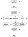
- At step 200 at least one first impedance value indicative of the impedance of at least one segment of the subject's leg is determined. This may be achieved by having the signal generators 117A, 117B, apply at least one first signal to the subject S, via the first electrodes 113A, 113B, with voltage signals being measured across the subject S by the sensors 118A, 118B, via the second electrodes 115A, 115B. An indication of the current flow through and voltage across the subject is provided to the processing system 102, allowing the impedance, or an impedance parameter value to be determined.
- an indicator is determined using the first impedance.
- the indicator is typically indicative of the extracellular fluid levels within the subject.
- the impedance measurement is performed at a single low frequency, such as below 100 kHz, and in one example, at 5 kHz, allowing the indicator to be based on the measured value directly.
- multiple measurements may be performed at multiple frequencies, with the indicator being based on an appropriate impedance parameter value derived therefrom, such as the impedance at zero applied frequency R 0 , as will be described in more detail below.
- the indicator can be used in the assessment of venous insufficiency, or other conditions, such as oedema or lymphoedema.
- high extracellular fluid levels in the leg segment are indicative of oedema in the leg, which is in turn an indicator that venous insufficiency may be present.
- the indicator can be compared to a reference, such as an oedema reference, to allow the presence, absence or degree of oedema to be determined, as will be described in more detail below.
- the subject can be treated for venous insufficiency. This can be performed in any one of a number of manners, such as by performing ablation, or the like.
- the impedance measurement described above is repeated to allow a post-treatment indicator to be determined. Any difference between the pre-treatment indicator determined prior to treatment, and the post-treatment indicator, can be used to determine if there has been a reduction in the extra-cellular fluid levels. Any reduction in fluid levels indicates that the treatment has been at least partially successful, thereby allowing the presence of venous insufficiency to be confirmed at step 250.
- both measurements are typically made with the subject in a standing or equivalent position, such as leaning or sitting with their leg hanging in a substantially vertical position, to thereby enhance the impact of blood pooling caused by venous insufficiency on extracellular fluid levels.
- standing will be understood to encompass any position that maximises or enhances pooling of blood in the subject's leg.
- the subject is reorientated from an orientation used to determine the first indicator, allowing a change in indicator between different orientations to be determined at step 270.
- the first indicator can be determined with the subject provided in a first orientation, to allow a baseline reading to be established. In one example, this is performed with the subject in an orientation designed to reduce or minimise blood pooling, such as with the subject in a supine position, and optionally with their leg elevated to a height of up to 20 cm above the level of their heart.
- the term supine will be understood to encompass any position that minimises pooling of blood in the subject's leg.
- the subject then stands, leans or sits with their leg hanging in a substantially vertical position, allowing a second indicator to be determined, with a change in indicator values being indicative of the change of extracellular fluid levels within the leg, which in turn can be used in venous insufficiency assessment.
- the subject can be allowed to stand to allow pooling of blood. Following this, the subject is returned to the supine position allowing the indicator value to be monitored. The time taken for this return to the baseline, or to within a range of the threshold, can then be used in venous insufficiency assessment.
- second impedance measurements are performed to allow an index to be determined at step 290.
- the index is typically indicative of a ratio between intracellular and extracellular fluid levels in the leg, or a leg segment, which can in turn be used to assess the presence of lymphoedema. Being able to distinguish between oedema and lymphoedema can assist in assessing venous insufficiency.
- the measurements are performed on the subject's leg as this maximises the effect of any blood pooling, thereby maximising the effectiveness of the measurement procedure to determine indicators that can be used in identifying venous insufficiency.
- the process can be applied to other body segments, such as arms, as will be described in more detail below.
- the measuring system 300 includes a computer system 310 and a separate measuring device 320.
- the measuring device 320 includes a processing system 330 coupled to an interface 321 for allowing wired or wireless communication with the computer system 310.
- the processing system 330 may also be optionally coupled to one or more stores, such as different types of memory, as shown at 322, 323, 324, 325, 326.
- the interface is a Bluetooth stack, although any suitable interface may be used.
- the memories can include a boot memory 322, for storing information required by a boot-up process, and a programmable serial number memory 323, that allows a device serial number to be programmed.
- the memory may also include a ROM (Read Only Memory) 324, flash memory 325 and EPROM (Electronically Programmable ROM) 326, for use during operation. These may be used for example to store software instructions and to store data during processing, as will be appreciated by persons skilled in the art.
- ADCs analogue to digital converters
- DACs digital to analogue converters
- a controller such as a microprocessor, microcontroller or programmable logic device, may also be provided to control activation of the processing system 330, although more typically this is performed by software instructions executed by the processing system 330.
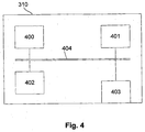
- the computer system 310 includes a processor 400, a memory 401, an input/output device 402 such as a keyboard and display, and an external interface 403 coupled together via a bus 404, as shown.
- the external interface 403 can be used to allow the computer system to communicate with the measuring device 320, via wired or wireless connections, as required, and accordingly, this may be in the form of a network interface card, Bluetooth stack, or the like.
- the computer system 310 can be used to control the operation of the measuring device 320, although this may alternatively be achieved by a separate interface provided on the measuring device 300. Additionally, the computer system 310 can be used to allow at least part of the analysis of the impedance measurements to be performed.
- the computer system 310 may be formed from any suitable processing system, such as a suitably programmed PC, Internet terminal, lap-top, hand-held PC, smart phone, PDA, server, or the like, implementing appropriate applications software to allow required tasks to be performed.
- a suitably programmed PC such as a PC, Internet terminal, lap-top, hand-held PC, smart phone, PDA, server, or the like, implementing appropriate applications software to allow required tasks to be performed.
- the processing system 330 typically performs specific processing tasks, to thereby reduce processing requirements on the computer system 310.
- the processing system typically executes instructions to allow control signals to be generated for controlling the signal generators 117A, 117B, as well as the processing to determine instantaneous impedance values.
- the processing system 330 is formed from custom hardware, or the like, such as a Field Programmable Gate Array (FPGA), although any suitable processing module, such as a magnetologic module, may be used.
- FPGA Field Programmable Gate Array
- the processing system 330 includes programmable hardware, the operation of which is controlled using instructions in the form of embedded software instructions.
- programmable hardware allows different signals to be applied to the subject S, and allows different analysis to be performed by the measuring device 320.
- different embedded software would be utilised if the signal is to be used to analyse the impedance at a number of frequencies simultaneously as compared to the use of signals applied at different frequencies sequentially.
- the embedded software instructions used can be downloaded from the computer system 310.
- the instructions can be stored in memory such as the flash memory 325 allowing the instructions used to be selected using either an input device provided on the measuring device 320, or by using the computer system 310.
- the computer system 310 can be used to control the instructions, such as the embedded software, implemented by the processing system 330, which in turn alters the operation of the processing system 330.
- the computer system 310 can operate to analyse impedance determined by the processing system 330, to allow biological parameters to be determined.
- the use of the processing system 330 more easily allows the custom hardware configuration to be adapted through the use of appropriate embedded software. This in turn allows a single measuring device to be used to perform a range of different types of analysis.
- a custom configured processing system 330 reduces the processing requirements on the computer system 310. This in turn allows the computer system 310 to be implemented using relatively straightforward hardware, whilst still allowing the measuring device to perform sufficient analysis to provide interpretation of the impedance. This can include for example generating a "Wessel" plot, using the impedance values to determine parameters relating to cardiac function, as well as determining the presence or absence of lymphoedema.
- the measuring device 320 can be updated.
- the measuring device can be updated by downloading new embedded software via flash memory 325 or the external interface 321.
- the processing system 330 In use, the processing system 330 generates digital control signals, which are converted to analogue voltage drive signals V D by the DACs 329, and transferred to the signal generators 117. Analogue signals representing the current of the drive signal I D applied to the subject and the subject voltage V S measured at the second electrodes 115A, 115B are received from the signal generators 117 and the sensors 118 and are digitised by the ADCs 327, 328. The digital signals can then be returned to the processing system 330 for preliminary analysis.
- a respective set of ADCs 327, 328, and DACs 329 are used for each of two channels, as designated by the reference numeral suffixes A, B respectively.
- This allows each of the signal generators 117A, 117B to be controlled independently and for the sensors 118A, 118B to be used to detect signals from the electrodes 115A, 115B respectively.
- This therefore represents a two channel device, each channel being designated by the reference numerals A, B.
- any number of suitable channels may be used, depending on the preferred implementation.
- an arrangement of eight ADCs 327, 328, and four DACs 329 could be used, so each channel has respective ADCs 327, 328, and DACs 329.
- other arrangements may be used, such as through the inclusion of a multiplexing system for selectively coupling a two-channel arrangement of ADCs 327, 328, and DACs 329 to a four channel electrode arrangement, as will be appreciated by persons skilled in the art.
- the electrodes are positioned on the subject as required.
- the general arrangement to allow impedance of a leg to be determined is to provide drive electrodes 113A, 113B on the hand at the base of the knuckles and on the feet at the base of the toes, on the side of the body being measured.
- Sense electrode 115A are also positioned at the front of the ankle on the leg being measured, with the sense electrode 115B being positioned anywhere on the contra-lateral leg.
- this configuration uses the theory of equal potentials, allowing the electrode positions to provide reproducible results for impedance measurements. This is advantageous as it greatly reduces the variations in measurements caused by poor placement of the electrodes by the operator.
- the sense electrodes can be provided anywhere on the leg of interest, allowing the impedance measurements to be made along the entire leg, or for a part of the leg (generally referred to as a leg segment), such as a calf segment, or the like.
- an impedance measurement type is selected using the computer system 310, allowing the processing system to determine an impedance measurement protocol, and configure the processing system 330 accordingly. This is typically achieved by configuring firmware or software instructions within the processing system 330, as described above.
- the processing system 300 selects a next measurement frequency f i , and causes the signal generators 117A, 117B to apply a first signal to the subject at the selected frequency at step 530.
- the signal generators 117A, 117B and sensors 118A, 118B provide an indication of the current through and the voltage across the leg segment to the processing system 330.
- the processing system 330 determines if all frequencies are complete, and if not returns to step 520 to select the next measurement frequency.
- one or more measured impedance values are determined, by the computer system 310, the processing system 330, or a combination thereof, using the techniques described above.
- One or more impedance parameter values may optionally be derived at step 570.
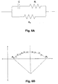
- Figure 6A is an example of an equivalent circuit that effectively models the electrical behaviour of biological tissue.
- the equivalent circuit has two branches that represent current flow through extracellular fluid and intracellular fluid, respectively.
- the extracellular fluid component of biological impedance is represented by an extracellular resistance R e
- the intracellular fluid component is represented by an intracellular resistance R i and a capacitance C representative of the cell membranes.
- impedance parameters R 0 , R ⁇ or Z c may be determined in any one of a number of manners such as by:
- the Wessel plot is often used in BIS (Bioimpedance Spectroscopy) Bioimpedance Spectroscopy (BIS) devices, which perform multiple measurements over a range of frequencies, such as from 4 kHz to 1000 kHz, using 256 or more different frequencies within this range.
- BIS Bioimpedance Spectroscopy
- BIOS Bioimpedance Spectroscopy
- the regression analysis is computationally expensive, requiring a device with significant processing power to perform the calculations, which in turn results in relatively high power usage by the apparatus, requiring a larger battery, and adding to the weight and size of the apparatus.
- a further issue is that a large number of data points are required to perform the regression analysis, and as measurements are typically performed at each frequency sequentially, the measurement process takes a significant amount of time, such as several seconds. This is undesirable as remaining still for long periods of time can cause discomfort for the subject. Additionally, the subject may move during the measurement procedure, which can affect the measured impedance values, for example due to changes in capacitive and/or inductive coupling between the subject and environment, leads and electrodes. This can lead to inaccuracies in the measured values.
- a circle may be uniquely defined by the co-ordinates of three points (x 1-3 , y 1-3 ) located on the locus, as shown in Figure 4 . Accordingly, three simultaneous equations can be defined, one for each of three loci that describe the circle that fits these points, as shown by equations (4) below.
- this technique allows a value for R 0 and optionally R ⁇ to be derived in a computationally less expensive manner than if a regression analysis is performed. Additionally, this also requires a reduced number of data points. This allows a value of R 0 to be determined more rapidly, and with a more basic processor than can be achieved using BIS and regression analysis, which in turn renders the device required to determine a value of R 0 less expensive to manufacture.
- this is achieved by performing impedance measurements at at least three frequencies. Indications of the signals are used to determine first and second impedance parameter values at each of the frequencies.
- the nature of the impedance parameter values will vary depending on the preferred implementation.
- the impedance parameter values could include magnitude and phase information relating to the measured signals.
- the impedance parameter values are indicative of the resistance and reactance, as derived from the magnitude and phase signals.
- simultaneous equations are solved using the first and second impedance parameter values determined at each of the three frequencies, thereby allowing circle parameters to be determined.
- the circle parameters are used to define a locus corresponding to at least part of an arc of a circle in a space defined by the parameter values.
- the simultaneous equations represent a circular locus provided in a reactance/resistance space, similar to the Wessel plot described above.
- Theoretical impedance parameter values such as R 0 and R ⁇ can then be determined from the circle parameters.
- impedance measurements are performed at more than three frequencies, with circle parameters for all possible combinations of impedance measurements at three frequencies being calculated.
- the average can be provided along with the standard deviation as a measure of the goodness of fit of the data to the Cole model.
- this can be accounted for by excluding one or more outlier measurements, such as measurements that deviates the greatest amount from the mean, or measurements differing by more than a set number of standard deviations from the mean, allowing the mean to be recalculated, thereby providing more accurate values.
- this process uses additional measurements, such as four or five measurements, this is still significantly less than the 256 or more frequencies typically performed using a BIS measurement protocol, allowing the measurement process to be performed more quickly.
- the frequencies used are in the range 0 kHz to 1000 kHz, and in one specific example, four measurements are recorded at frequencies of 25 kHz, 50 kHz, 100 kHz, and 200 kHz, although any suitable measurement frequencies can be used.
- a further alternative for determining impedance parameter values such as R 0 and R ⁇ is it perform impedance measurements at a single frequency, and use these as an estimate of the parameter values.
- measurements performed at a single low frequency can be used to estimate R 0
- measurements at a single high frequency can be used to estimate R ⁇ .
- the above described equivalent circuit models the resistivity as a constant value and does not therefore accurately reflect the impedance response of a subject, and in particular does not accurately model the change in orientation of the erythrocytes in the subject's blood stream, or other relaxation effects.
- an improved CPE based model may alternatively be used.
- At step 700 at least one first impedance value is determined using the method described above.
- the measurement is typically performed with the subject in a specific orientation, such as in a supine or standing position. This is performed to either maximise or minimise the effect of blood pooling, and this will depend on the analysis performed.
- the subject is made to stand for a set time period such as between five and fifteen minutes to maximize the effect of any blood pooling.
- a marked increase in blood pooling is achieved after five minutes, with the blood levels reaching a relatively static maximum after approximately fifteen minutes. Accordingly, whilst it is preferable for the subject to stand for fifteen minutes to thereby maximise blood pooling, even after five minutes sufficient pooling occurs to allow measurements to be performed.
- the length of time selected may depend on factors such as the amount of time available for the measurement process and the ability of the subject to remain in standing position.
- the subject may be required to lay in a supine position for a set time period, such as five to fifteen minutes prior to standing. This can be performed to minimise any blood pooling before standing, so as to provide a more accurate baseline status for the subject prior to measurements being performed. Again, a marked reduction in pooling is achieved after five minutes, with the level of pooling typically reaching a reasonably static minimum after approximately fifteen minutes, so the length of time used will depend on factors such as the amount of time available to make a measurement.
- an impedance parameter value R 0 is optionally determined. This can be performed if multiple impedance values are determined. Otherwise, a single impedance measurement can be made at a low frequency, such as below 10 kHz, as this provides a reasonably close approximation of R 0 .
- an indicator that is indicative of the extracellular R e fluid levels within the subject is determined, with this being displayed to the user at step 730.
- the indicator can be any form of suitable indicator such as a numerical value based on the value of the impedance parameter value R 0 .
- the indicator may also be scaled to provide a numerical value that is indicative of the presence, absence or degree of venous insufficiency or oedema.
- the indicator can also be based on the results of a comparison of a numerical value to a reference, such as an oedema reference.
- the oedema reference could be any suitable form of reference.
- the oedema reference can be based on an equivalent impedance parameter value determined for a different limb of the subject, such as an arm. This is possible, as, for a subject not suffering from venous insufficiency, there is a predictable relationship between the extracellular fluid levels between different limbs. Thus, for example, if the subject is suffering from a condition other than venous insufficiency, which causes a general change in extracellular fluid levels, then this should affect body segments in an assessable manner, thereby allowing venous insufficiency to be identified.
- Minor variations in tissue may occur between different body segments in a healthy subject, and this can be accounted for by providing a tolerance to the comparison. Thus, for example, this could take into account naturally expected variations between different limbs in normal healthy subjects, for example due to limb dominance, previous analysis for the subject, or the like.
- the tolerance may also depend on a number of factors, such as the subject's age, weight, sex and height, and again a respective range can be selected based on these factors.
- the oedema reference can be based on a reference derived from sample populations, or the like.
- the oedema reference can be selected based on the subject parameters, so that the value of the indicator is compared to values of the indicator derived from a study of a sample population of other individuals having similar subject parameters.
- the oedema reference can be based on a previously measured reference for the subject, for example determined before the subject suffered from venous insufficiency or oedema. This allows a longitudinal analysis to be performed, thereby allowing the onset or progression of venous insufficiency to be assessed.
- the indicator can additionally and/or alternatively be displayed on a graphical linear or nonlinear scale, with the position of a pointer on the scale being indicative of extracellular fluid levels and or the presence, absence or degree of oedema or venous insufficiency.
- the linear scale can include thresholds at values representing ranges indicative of the presence or absence of oedema or venous insufficiency, as derived from sample population data, or other references.
- the user can use the indicator to assess whether further investigation is required.
- a high extra-cellular fluid level indicative of the presence of oedema is a good indication that the subject has venous insufficiency, but this may need to be confirmed with further measurements, and/or analysis.
- the above described example allows for a rapid assessment of the presence of venous insufficiency.
- This can be performed using BIA, which allows relatively simple apparatus and processing to be used, thereby reducing the cost of equipment required to assess venous insufficiency compared to more complex techniques.
- the process is more reliable than current non-invasive techniques such as SPG and APG.
- changes in fluid levels can typically be detected using impedance measurements before the fluid level changes have a noticeable impact on limb volume, thereby making the impedance measurement process more sensitive than other techniques such as SPG or APG.
- a first indicator value is determined with the subject in a standing position, as described with respect to Figure 7 , to maximise blood pooling. This is performed before the subject is treated so that the first indicator acts as a pre-treatment indicator.
- the subject is treated for venous insufficiency, by performing ablation, or the like.
- a second indicator value is determined using a similar technique, (i.e. with the subject in a standing position) which acts as a post-treatment indicator.
- the processing system 102 determines any difference between the first and second indicator values at step 830, with the difference being compared to a reference, such as a treatment reference at step 840, thereby allowing the relevance of any change to be assessed. If the comparison indicates that there is a reduction in the extra-cellular fluid levels greater than a threshold amount, then this indicates that the treatment is successful or has at least had an impact, thereby allowing the presence of venous insufficiency to be confirmed at step 850. The magnitude of any difference may also be used to determine the degree of any venous insufficiency, and/or the effectiveness of the treatment.
- treatment reference can be derived in any one of a number of manners.
- treatment reference can be obtained from data collected from a sample population of subjects, which acts as a pool of data from which normalised expected differences for successfully treated, untreated and/or healthy subjects can be determined.
- the treatment reference is then generated by selecting reference values that are determined to be relevant to the test subject based on the subject parameters such as age, sex, height, weight, race, interventions, or the like.
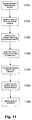
- a first indicator value is determined with the subject in a supine position. This measurement is typically performed after the subject has been allowed to rest for some set time, such as five to fifteen minutes. This reduces the effect of any blood pooling, allowing a baseline reading to be established. The subject then stands for a predetermined time period, such as five to fifteen minutes, to maximize blood pooling before a second indicator value is determined using the technique described above, at step 910.
- the first and second indicator values are indicative of extra-cellular fluid levels, and therefore could be based on one or more low frequency impedance measurements or the impedance parameter value R 0 , as derived from impedance measurements in some manner.
- the processing system 102 determines any difference between the first and second indicator values, with the difference being compared to a reference, such as a pooling reference, at step 930.
- the pooling reference can be based on similar indicator values derived from sample populations, or the like.
- the pooling reference can be based on first and second indicator values previously determined for the subject, for example prior to the onset of venous insufficiency, allowing longitudinal analysis to be performed.
- the reference is determined as a percentage change from the baseline reading, so that a change of less than a predetermined amount, such as 15%, indicates that the subject does not have venous insufficiency.
- a percentage change greater than the predetermined amount, such as 15% this indicates that the level of pooling is abnormal, and hence that the subject may have venous insufficiency, with the magnitude of the percentage change being indicative of the degree of venous insufficiency.
- a change of greater than 20 % would typically be indicative of venous insufficiency.
- Results of the comparison can be displayed at step 940, to allow the relevance of any change to be assessed.
- the comparison indicates that there is an increase in the extra-cellular fluid levels greater than an amount determined from the pooling reference, then this indicates that there is significant blood pooling within the subject, which is in turn indicative of venous insufficiency.
- the magnitude of the difference between the first and second indicator values can be indicative of the degree of venous insufficiency.
- the subject is reorientated and the measurement re-performed.
- the indicator derived in the process of Figure 7 is made in the standing position, then this can act as the second indicator, with the subject being reorientated to allow the first indicator to be determined.
- first and second are used to identify respective indicators and do not necessarily imply or require an order to the measurements.
- the first indicator is measured first to allow an accurate baseline to be established, although this is not essential. This allows a more reliable assessment of venous insufficiency than achievable with prior art techniques, and allows the analysis to be confirmed using the same apparatus as used to perform the initial assessment. This also allows assessment to be confirmed without requiring treatment of the subject, which can reduce the cost burden of the assessment.
- a first indicator value is determined with the subject in a supine position. As in the previous example, this is performed to allow a baseline reading to be established. The subject then stands for a predetermined time period, such as five to fifteen minutes, to maximize blood pooling at step 1010, before returning to a supine position to allow a second indicator value to be determined using the technique described above, at step 1020.
- the processing system 102 determines any difference between the first and second indicator values, before determining if the difference is below a reference, such as a return reference, at step 1040. If not, the process returns to step 1020, allowing a new second indicator to be determined.
- the reference may be derived from sample populations, previous measurements for the subject, or the like. Alternatively, the reference is deemed to be a certain percentage variation from the baseline reading. Thus, in this example, the time taken to return to within 5-10% of the baseline reading can be determined.
- Steps 1020 to 1040 are repeated until the difference between the first and second indicators is below the return reference.
- the length of time taken for the difference to fall below the pooling reference is determined, with this being displayed to the user at step 1060.
- the time taken to return to the baseline (or the reference) is less than a reference amount, such as fifteen minutes, then this is indicative that the subject does not have venous insufficiency. However, if the time taken is greater than the reference time, then this is indicative that the subject does have venous insufficiency.
- the amount of blood will return to the baseline amount relatively quickly, whilst in a subject with venous insufficiency, this can take several minutes. Accordingly, the time taken for blood pooling in the leg to be reduced is in turn indicative of the presence, absence or degree of venous insufficiency.
- the return reference is used to take into account natural variation and to allow the measurement to be performed in a reasonable time period.
- this process can be used to help assess the presence of venous insufficiency. For example, if measurements are performed on the subject's leg, and it is determined that the subject has oedema but not lymphoedema, then this is indicative that the subject has venous insufficiency.
- this technique can be used to distinguish between oedema and lymphoedema in other body segments, such as arms. This can be used in helping to identify optimum management programmes depending on the conditions suffered by the subject.
- the technique will be described as being generally applied to a body segment to allow oedema and lymphoedema to be distinguished. It will be appreciated that in the event that this technique is used for identifying venous insufficiency, then the process will be performed on the subject's leg, but that the process could also be applied to other body segments.
- impedance values are determined for the body segment at a number of different frequencies. If this technique is being used to determine indicators that can be used in identifying venous insufficiency, then these measurements are typically performed with the subject in a standing position to maximise blood pooling.
- the processing system 102 determines values for the impedance parameters R 0 , R ⁇ as described in more detail above. Thus, this could be performed using regression analysis applied to BIS measurements. Alternatively, the process could use MFBIA, and solving of simultaneous equations to determine the impedance parameter values. Other techniques could also be used as appropriate in which combinations of individual measurements at selected frequencies are used. Thus, for example, single measurements at low and high frequencies respectively could be used as an estimate of R 0 and R ⁇ .
- a first indicator value is determined using the impedance parameter value R 0 . It will be appreciated that this can alternatively be derived from a single low frequency impedance measurement described above, although in another example, measurements at multiple frequencies can be used for subsequent steps, in which case the need to make additional single frequency measurements can be avoided.
- an index is determined for the body segment which provides an indication of the distribution between intra and extracellular fluids.
- the index is indicative of the ratio of extracellular fluid to intracellular fluid R i / R e .
- the first indicator value is compared to a first reference, such as the oedema reference described above, with the results of the comparison allowing the presence of oedema to be determined.
- the index value is compared to a second reference, with the results of the comparison allowing determination of whether the subject has lymphoedema.
- the second reference can be determined in any one of a number of manners.
- the index is compared to a reference index value determined for another limb.
- a reference index value determined for another limb.
- This is possible, as, for a subject not having lymphoedema, there is generally a degree of similarity of intra- and extra-cellular fluid levels, even between different body segments. Typically minor variations in tissue will occur between different body segments, for example due to inherent differences between different types of limb, or due to limb dominance, and this can be accounted for using appropriate tolerances in a manner similar to that described above.
- different references can be used, such as references derived from sample populations, previous measurements made for the subject, or the like.
- the results of the comparison can be displayed to the user to allow assessment of whether the subject has oedema and/or lymphoedema.
- the magnitude of the indicator and index values can be used to assess the degree of venous insufficiency.
- this technique can be used on other parts of the body to distinguish between oedema and lymphoedema.
- the above described process can be repeated with the subject in supine and standing positions.
- changes in the indicator and index values can further assist in assessing the presence, absence or degree of venous insufficiency.
- this can provide a more accurate indication of venous insufficiency severity than can be achieved using the prior art or other techniques. Furthermore, by using the BIS apparatus described above, the assessment can be performed rapidly, without requiring the subject to undergo exercise regimes, which may not be appropriate for some subjects.
- impedance generally refers to a measured impedance value or impedance parameter value derived therefrom.
- resistance refers to any measured value relating to the impedance, such as admittance of reactance measurements.
- processing system is intended to include any component capable of performing processing and can include any one or more of a processing system and a computer system.
- the measuring device and techniques described above can be used with any animal, including but not limited to, primates, livestock, performance animals, such race horses, or the like.
- the above described processes can be used in determining biological indicators, which in turn can be used for diagnosing the presence, absence or degree of a range of conditions and illnesses, including, but not limited to oedema, lymphodema, body composition, or the like.
- impedance measurement covers admittance and other related measurements.
Landscapes
- Health & Medical Sciences (AREA)
- Life Sciences & Earth Sciences (AREA)
- Biomedical Technology (AREA)
- Heart & Thoracic Surgery (AREA)
- Radiology & Medical Imaging (AREA)
- Biophysics (AREA)
- Pathology (AREA)
- Engineering & Computer Science (AREA)
- Nuclear Medicine, Radiotherapy & Molecular Imaging (AREA)
- Physics & Mathematics (AREA)
- Medical Informatics (AREA)
- Molecular Biology (AREA)
- Surgery (AREA)
- Animal Behavior & Ethology (AREA)
- General Health & Medical Sciences (AREA)
- Public Health (AREA)
- Veterinary Medicine (AREA)
- Measurement And Recording Of Electrical Phenomena And Electrical Characteristics Of The Living Body (AREA)
Applications Claiming Priority (2)
| Application Number | Priority Date | Filing Date | Title |
|---|---|---|---|
| US2927208P | 2008-02-15 | 2008-02-15 | |
| PCT/AU2009/000163 WO2009100491A1 (en) | 2008-02-15 | 2009-02-12 | Analysing impedance measurements |
Publications (3)
| Publication Number | Publication Date |
|---|---|
| EP2242423A1 EP2242423A1 (en) | 2010-10-27 |
| EP2242423A4 EP2242423A4 (en) | 2013-05-22 |
| EP2242423B1 true EP2242423B1 (en) | 2016-04-13 |
Family
ID=40956556
Family Applications (1)
| Application Number | Title | Priority Date | Filing Date |
|---|---|---|---|
| EP09710912.8A Not-in-force EP2242423B1 (en) | 2008-02-15 | 2009-02-12 | Analysing impedance measurements |
Country Status (5)
| Country | Link |
|---|---|
| EP (1) | EP2242423B1 (enExample) |
| JP (2) | JP2011511679A (enExample) |
| AU (1) | AU2009214826B2 (enExample) |
| CA (1) | CA2714367A1 (enExample) |
| WO (1) | WO2009100491A1 (enExample) |
Families Citing this family (19)
| Publication number | Priority date | Publication date | Assignee | Title |
|---|---|---|---|---|
| AUPQ113799A0 (en) | 1999-06-22 | 1999-07-15 | University Of Queensland, The | A method and device for measuring lymphoedema |
| US8744564B2 (en) | 2004-06-18 | 2014-06-03 | Impedimed Limited | Oedema detection |
| EP1827222A1 (en) | 2004-11-26 | 2007-09-05 | Z-Tech (Canada) Inc. | Weighted gradient method and system for diagnosing disease |
| EP2449964B1 (en) | 2005-07-01 | 2016-08-10 | Impedimed Limited | Connector for Impedance Measurement System |
| EP1898784B1 (en) | 2005-07-01 | 2016-05-18 | Impedimed Limited | Method and apparatus for performing impedance measurements |
| US9724012B2 (en) | 2005-10-11 | 2017-08-08 | Impedimed Limited | Hydration status monitoring |
| CA2653406C (en) | 2006-05-30 | 2015-03-17 | The University Of Queensland | Impedance measurements |
| JP5372768B2 (ja) | 2006-11-30 | 2013-12-18 | インぺディメッド リミテッド | 測定装置 |
| AU2008241356B2 (en) | 2007-04-20 | 2013-10-03 | Impedimed Limited | Monitoring system and probe |
| JP5513396B2 (ja) | 2007-11-05 | 2014-06-04 | インぺディメッド リミテッド | インピーダンス確定方法及び装置 |
| AU2008207672B2 (en) | 2008-02-15 | 2013-10-31 | Impedimed Limited | Impedance Analysis |
| US20110301489A1 (en) * | 2008-11-10 | 2011-12-08 | Impedimed Limited | Fluid indicator |
| US9615766B2 (en) | 2008-11-28 | 2017-04-11 | Impedimed Limited | Impedance measurement process |
| WO2011039708A2 (en) * | 2009-10-02 | 2011-04-07 | Koninklijke Philips Electronics N.V. | Signal transmission through a medium |
| CA2777797A1 (en) | 2009-10-26 | 2011-05-05 | Impedimed Limited | Fluid level indicator determination |
| JP5755234B2 (ja) | 2009-11-18 | 2015-07-29 | インぺディメッド リミテッドImpedimed Limited | 患者−電極間測定のための装置およびシステム |
| CA2782953A1 (en) * | 2009-12-21 | 2011-06-30 | Impedimed Limited | Analysing impedance measurements |
| EP3322335B1 (en) * | 2015-07-16 | 2021-01-20 | Impedimed Limited | Fluid level determination |
| WO2021263091A1 (en) * | 2020-06-26 | 2021-12-30 | Georgia Tech Research Corporation | Systems and methods for joint health assessment |
Family Cites Families (12)
| Publication number | Priority date | Publication date | Assignee | Title |
|---|---|---|---|---|
| US3996924A (en) * | 1974-06-19 | 1976-12-14 | Wheeler H Brownell | Occlusive impedance phlebograph and method therefor |
| JP3699640B2 (ja) * | 2000-08-01 | 2005-09-28 | 株式会社タニタ | 多周波生体インピーダンス測定による体水分量状態判定装置 |
| JP3943955B2 (ja) * | 2002-02-25 | 2007-07-11 | 株式会社タニタ | 深部静脈血栓症判定装置 |
| AT413189B (de) * | 2002-10-07 | 2005-12-15 | Cnsystems Medizintechnik Gmbh | Medizinisches elektroden-element |
| US7783345B2 (en) * | 2002-10-07 | 2010-08-24 | Cnsystems Medizintechnik Gmbh | Impedance-based measuring method for hemodynamic parameters |
| US8744564B2 (en) * | 2004-06-18 | 2014-06-03 | Impedimed Limited | Oedema detection |
| US20060111652A1 (en) | 2004-11-22 | 2006-05-25 | Mcleod Kenneth J | Method for enhancing blood and lymph flow in the extremities |
| AU2006265762B2 (en) * | 2005-07-01 | 2012-08-16 | Impedimed Limited | Pulmonary monitoring system |
| EP1898784B1 (en) * | 2005-07-01 | 2016-05-18 | Impedimed Limited | Method and apparatus for performing impedance measurements |
| EP2449964B1 (en) * | 2005-07-01 | 2016-08-10 | Impedimed Limited | Connector for Impedance Measurement System |
| US9724012B2 (en) * | 2005-10-11 | 2017-08-08 | Impedimed Limited | Hydration status monitoring |
| AT502921B1 (de) * | 2005-10-21 | 2012-01-15 | Falko Dr Skrabal | Gerät zur messung von herz- und gefässfunktion (function) und körperräumen (spaces) mit hilfe der impedanzmessung |
-
2009
- 2009-02-12 AU AU2009214826A patent/AU2009214826B2/en not_active Ceased
- 2009-02-12 EP EP09710912.8A patent/EP2242423B1/en not_active Not-in-force
- 2009-02-12 WO PCT/AU2009/000163 patent/WO2009100491A1/en not_active Ceased
- 2009-02-12 JP JP2010546182A patent/JP2011511679A/ja active Pending
- 2009-02-12 CA CA2714367A patent/CA2714367A1/en not_active Abandoned
-
2014
- 2014-10-22 JP JP2014215681A patent/JP6089016B2/ja not_active Expired - Fee Related
Non-Patent Citations (1)
| Title |
|---|
| FENECH M ET AL: "Extracellular and Intracellular Volume Variations During Postural Change Measured by Segmental and Wrist-Ankle Bioimpedance Spectroscopy", IEEE TRANSACTIONS ON BIOMEDICAL ENGINEERING, IEEE SERVICE CENTER, PISCATAWAY, NJ, USA, vol. 51, no. 1, 1 January 2004 (2004-01-01), pages 166 - 175, XP011104178, ISSN: 0018-9294, DOI: 10.1109/TBME.2003.820338 * |
Also Published As
| Publication number | Publication date |
|---|---|
| JP2011511679A (ja) | 2011-04-14 |
| AU2009214826B2 (en) | 2014-12-18 |
| EP2242423A1 (en) | 2010-10-27 |
| CA2714367A1 (en) | 2009-08-20 |
| EP2242423A4 (en) | 2013-05-22 |
| AU2009214826A1 (en) | 2009-08-20 |
| WO2009100491A1 (en) | 2009-08-20 |
| JP6089016B2 (ja) | 2017-03-01 |
| JP2015037600A (ja) | 2015-02-26 |
Similar Documents
| Publication | Publication Date | Title |
|---|---|---|
| EP2242423B1 (en) | Analysing impedance measurements | |
| US20110060239A1 (en) | Analysing impedance measurements | |
| EP2515755B1 (en) | Analysing impedance measurements | |
| US9392947B2 (en) | Blood flow assessment of venous insufficiency | |
| US9504406B2 (en) | Measurement apparatus | |
| US11612332B2 (en) | Hydration status monitoring | |
| CA2686883C (en) | Indicator | |
| AU2012212386B2 (en) | Tissue mass indicator determination | |
| AU2011274290B2 (en) | Tissue indicator determination | |
| Dubiel | Bioelectrical impedance analysis in medicine | |
| US12336801B2 (en) | Indicator determination | |
| AU2006301927B2 (en) | Hydration status monitoring |
Legal Events
| Date | Code | Title | Description |
|---|---|---|---|
| PUAI | Public reference made under article 153(3) epc to a published international application that has entered the european phase |
Free format text: ORIGINAL CODE: 0009012 |
|
| 17P | Request for examination filed |
Effective date: 20100804 |
|
| AK | Designated contracting states |
Kind code of ref document: A1 Designated state(s): AT BE BG CH CY CZ DE DK EE ES FI FR GB GR HR HU IE IS IT LI LT LU LV MC MK MT NL NO PL PT RO SE SI SK TR |
|
| AX | Request for extension of the european patent |
Extension state: AL BA RS |
|
| DAX | Request for extension of the european patent (deleted) | ||
| REG | Reference to a national code |
Ref country code: HK Ref legal event code: DE Ref document number: 1149701 Country of ref document: HK |
|
| A4 | Supplementary search report drawn up and despatched |
Effective date: 20130424 |
|
| RIC1 | Information provided on ipc code assigned before grant |
Ipc: A61B 5/053 20060101AFI20130417BHEP |
|
| 17Q | First examination report despatched |
Effective date: 20140522 |
|
| GRAP | Despatch of communication of intention to grant a patent |
Free format text: ORIGINAL CODE: EPIDOSNIGR1 |
|
| INTG | Intention to grant announced |
Effective date: 20151021 |
|
| GRAS | Grant fee paid |
Free format text: ORIGINAL CODE: EPIDOSNIGR3 |
|
| GRAA | (expected) grant |
Free format text: ORIGINAL CODE: 0009210 |
|
| AK | Designated contracting states |
Kind code of ref document: B1 Designated state(s): AT BE BG CH CY CZ DE DK EE ES FI FR GB GR HR HU IE IS IT LI LT LU LV MC MK MT NL NO PL PT RO SE SI SK TR |
|
| REG | Reference to a national code |
Ref country code: GB Ref legal event code: FG4D |
|
| REG | Reference to a national code |
Ref country code: AT Ref legal event code: REF Ref document number: 789173 Country of ref document: AT Kind code of ref document: T Effective date: 20160415 Ref country code: CH Ref legal event code: EP |
|
| REG | Reference to a national code |
Ref country code: IE Ref legal event code: FG4D |
|
| REG | Reference to a national code |
Ref country code: DE Ref legal event code: R096 Ref document number: 602009037734 Country of ref document: DE |
|
| REG | Reference to a national code |
Ref country code: LT Ref legal event code: MG4D |
|
| REG | Reference to a national code |
Ref country code: AT Ref legal event code: MK05 Ref document number: 789173 Country of ref document: AT Kind code of ref document: T Effective date: 20160413 |
|
| REG | Reference to a national code |
Ref country code: NL Ref legal event code: MP Effective date: 20160413 |
|
| PG25 | Lapsed in a contracting state [announced via postgrant information from national office to epo] |
Ref country code: FI Free format text: LAPSE BECAUSE OF FAILURE TO SUBMIT A TRANSLATION OF THE DESCRIPTION OR TO PAY THE FEE WITHIN THE PRESCRIBED TIME-LIMIT Effective date: 20160413 Ref country code: NL Free format text: LAPSE BECAUSE OF FAILURE TO SUBMIT A TRANSLATION OF THE DESCRIPTION OR TO PAY THE FEE WITHIN THE PRESCRIBED TIME-LIMIT Effective date: 20160413 Ref country code: LT Free format text: LAPSE BECAUSE OF FAILURE TO SUBMIT A TRANSLATION OF THE DESCRIPTION OR TO PAY THE FEE WITHIN THE PRESCRIBED TIME-LIMIT Effective date: 20160413 Ref country code: NO Free format text: LAPSE BECAUSE OF FAILURE TO SUBMIT A TRANSLATION OF THE DESCRIPTION OR TO PAY THE FEE WITHIN THE PRESCRIBED TIME-LIMIT Effective date: 20160713 Ref country code: PL Free format text: LAPSE BECAUSE OF FAILURE TO SUBMIT A TRANSLATION OF THE DESCRIPTION OR TO PAY THE FEE WITHIN THE PRESCRIBED TIME-LIMIT Effective date: 20160413 |
|
| PG25 | Lapsed in a contracting state [announced via postgrant information from national office to epo] |
Ref country code: ES Free format text: LAPSE BECAUSE OF FAILURE TO SUBMIT A TRANSLATION OF THE DESCRIPTION OR TO PAY THE FEE WITHIN THE PRESCRIBED TIME-LIMIT Effective date: 20160413 Ref country code: LV Free format text: LAPSE BECAUSE OF FAILURE TO SUBMIT A TRANSLATION OF THE DESCRIPTION OR TO PAY THE FEE WITHIN THE PRESCRIBED TIME-LIMIT Effective date: 20160413 Ref country code: GR Free format text: LAPSE BECAUSE OF FAILURE TO SUBMIT A TRANSLATION OF THE DESCRIPTION OR TO PAY THE FEE WITHIN THE PRESCRIBED TIME-LIMIT Effective date: 20160714 Ref country code: SE Free format text: LAPSE BECAUSE OF FAILURE TO SUBMIT A TRANSLATION OF THE DESCRIPTION OR TO PAY THE FEE WITHIN THE PRESCRIBED TIME-LIMIT Effective date: 20160413 Ref country code: HR Free format text: LAPSE BECAUSE OF FAILURE TO SUBMIT A TRANSLATION OF THE DESCRIPTION OR TO PAY THE FEE WITHIN THE PRESCRIBED TIME-LIMIT Effective date: 20160413 Ref country code: AT Free format text: LAPSE BECAUSE OF FAILURE TO SUBMIT A TRANSLATION OF THE DESCRIPTION OR TO PAY THE FEE WITHIN THE PRESCRIBED TIME-LIMIT Effective date: 20160413 Ref country code: PT Free format text: LAPSE BECAUSE OF FAILURE TO SUBMIT A TRANSLATION OF THE DESCRIPTION OR TO PAY THE FEE WITHIN THE PRESCRIBED TIME-LIMIT Effective date: 20160816 |
|
| PG25 | Lapsed in a contracting state [announced via postgrant information from national office to epo] |
Ref country code: IT Free format text: LAPSE BECAUSE OF FAILURE TO SUBMIT A TRANSLATION OF THE DESCRIPTION OR TO PAY THE FEE WITHIN THE PRESCRIBED TIME-LIMIT Effective date: 20160413 Ref country code: BE Free format text: LAPSE BECAUSE OF FAILURE TO SUBMIT A TRANSLATION OF THE DESCRIPTION OR TO PAY THE FEE WITHIN THE PRESCRIBED TIME-LIMIT Effective date: 20160413 |
|
| REG | Reference to a national code |
Ref country code: FR Ref legal event code: PLFP Year of fee payment: 9 |
|
| REG | Reference to a national code |
Ref country code: DE Ref legal event code: R097 Ref document number: 602009037734 Country of ref document: DE |
|
| PG25 | Lapsed in a contracting state [announced via postgrant information from national office to epo] |
Ref country code: RO Free format text: LAPSE BECAUSE OF FAILURE TO SUBMIT A TRANSLATION OF THE DESCRIPTION OR TO PAY THE FEE WITHIN THE PRESCRIBED TIME-LIMIT Effective date: 20160413 Ref country code: DK Free format text: LAPSE BECAUSE OF FAILURE TO SUBMIT A TRANSLATION OF THE DESCRIPTION OR TO PAY THE FEE WITHIN THE PRESCRIBED TIME-LIMIT Effective date: 20160413 Ref country code: CZ Free format text: LAPSE BECAUSE OF FAILURE TO SUBMIT A TRANSLATION OF THE DESCRIPTION OR TO PAY THE FEE WITHIN THE PRESCRIBED TIME-LIMIT Effective date: 20160413 Ref country code: EE Free format text: LAPSE BECAUSE OF FAILURE TO SUBMIT A TRANSLATION OF THE DESCRIPTION OR TO PAY THE FEE WITHIN THE PRESCRIBED TIME-LIMIT Effective date: 20160413 Ref country code: SK Free format text: LAPSE BECAUSE OF FAILURE TO SUBMIT A TRANSLATION OF THE DESCRIPTION OR TO PAY THE FEE WITHIN THE PRESCRIBED TIME-LIMIT Effective date: 20160413 |
|
| PLBE | No opposition filed within time limit |
Free format text: ORIGINAL CODE: 0009261 |
|
| STAA | Information on the status of an ep patent application or granted ep patent |
Free format text: STATUS: NO OPPOSITION FILED WITHIN TIME LIMIT |
|
| 26N | No opposition filed |
Effective date: 20170116 |
|
| PGFP | Annual fee paid to national office [announced via postgrant information from national office to epo] |
Ref country code: FR Payment date: 20170112 Year of fee payment: 9 Ref country code: DE Payment date: 20170207 Year of fee payment: 9 |
|
| PG25 | Lapsed in a contracting state [announced via postgrant information from national office to epo] |
Ref country code: SI Free format text: LAPSE BECAUSE OF FAILURE TO SUBMIT A TRANSLATION OF THE DESCRIPTION OR TO PAY THE FEE WITHIN THE PRESCRIBED TIME-LIMIT Effective date: 20160413 |
|
| PGFP | Annual fee paid to national office [announced via postgrant information from national office to epo] |
Ref country code: GB Payment date: 20170208 Year of fee payment: 9 |
|
| REG | Reference to a national code |
Ref country code: HK Ref legal event code: WD Ref document number: 1149701 Country of ref document: HK |
|
| PG25 | Lapsed in a contracting state [announced via postgrant information from national office to epo] |
Ref country code: MC Free format text: LAPSE BECAUSE OF FAILURE TO SUBMIT A TRANSLATION OF THE DESCRIPTION OR TO PAY THE FEE WITHIN THE PRESCRIBED TIME-LIMIT Effective date: 20160413 |
|
| REG | Reference to a national code |
Ref country code: CH Ref legal event code: PL |
|
| PG25 | Lapsed in a contracting state [announced via postgrant information from national office to epo] |
Ref country code: CH Free format text: LAPSE BECAUSE OF NON-PAYMENT OF DUE FEES Effective date: 20170228 Ref country code: LI Free format text: LAPSE BECAUSE OF NON-PAYMENT OF DUE FEES Effective date: 20170228 |
|
| REG | Reference to a national code |
Ref country code: IE Ref legal event code: MM4A |
|
| PG25 | Lapsed in a contracting state [announced via postgrant information from national office to epo] |
Ref country code: LU Free format text: LAPSE BECAUSE OF NON-PAYMENT OF DUE FEES Effective date: 20170212 |
|
| PG25 | Lapsed in a contracting state [announced via postgrant information from national office to epo] |
Ref country code: IE Free format text: LAPSE BECAUSE OF NON-PAYMENT OF DUE FEES Effective date: 20170212 |
|
| REG | Reference to a national code |
Ref country code: DE Ref legal event code: R119 Ref document number: 602009037734 Country of ref document: DE |
|
| PG25 | Lapsed in a contracting state [announced via postgrant information from national office to epo] |
Ref country code: MT Free format text: LAPSE BECAUSE OF NON-PAYMENT OF DUE FEES Effective date: 20170212 |
|
| GBPC | Gb: european patent ceased through non-payment of renewal fee |
Effective date: 20180212 |
|
| REG | Reference to a national code |
Ref country code: FR Ref legal event code: ST Effective date: 20181031 |
|
| PG25 | Lapsed in a contracting state [announced via postgrant information from national office to epo] |
Ref country code: DE Free format text: LAPSE BECAUSE OF NON-PAYMENT OF DUE FEES Effective date: 20180901 |
|
| PG25 | Lapsed in a contracting state [announced via postgrant information from national office to epo] |
Ref country code: FR Free format text: LAPSE BECAUSE OF NON-PAYMENT OF DUE FEES Effective date: 20180228 Ref country code: GB Free format text: LAPSE BECAUSE OF NON-PAYMENT OF DUE FEES Effective date: 20180212 |
|
| PG25 | Lapsed in a contracting state [announced via postgrant information from national office to epo] |
Ref country code: HU Free format text: LAPSE BECAUSE OF FAILURE TO SUBMIT A TRANSLATION OF THE DESCRIPTION OR TO PAY THE FEE WITHIN THE PRESCRIBED TIME-LIMIT; INVALID AB INITIO Effective date: 20090212 |
|
| PG25 | Lapsed in a contracting state [announced via postgrant information from national office to epo] |
Ref country code: BG Free format text: LAPSE BECAUSE OF FAILURE TO SUBMIT A TRANSLATION OF THE DESCRIPTION OR TO PAY THE FEE WITHIN THE PRESCRIBED TIME-LIMIT Effective date: 20160413 |
|
| PG25 | Lapsed in a contracting state [announced via postgrant information from national office to epo] |
Ref country code: CY Free format text: LAPSE BECAUSE OF NON-PAYMENT OF DUE FEES Effective date: 20160413 |
|
| PG25 | Lapsed in a contracting state [announced via postgrant information from national office to epo] |
Ref country code: MK Free format text: LAPSE BECAUSE OF FAILURE TO SUBMIT A TRANSLATION OF THE DESCRIPTION OR TO PAY THE FEE WITHIN THE PRESCRIBED TIME-LIMIT Effective date: 20160413 |
|
| PG25 | Lapsed in a contracting state [announced via postgrant information from national office to epo] |
Ref country code: TR Free format text: LAPSE BECAUSE OF FAILURE TO SUBMIT A TRANSLATION OF THE DESCRIPTION OR TO PAY THE FEE WITHIN THE PRESCRIBED TIME-LIMIT Effective date: 20160413 |
|
| PG25 | Lapsed in a contracting state [announced via postgrant information from national office to epo] |
Ref country code: IS Free format text: LAPSE BECAUSE OF FAILURE TO SUBMIT A TRANSLATION OF THE DESCRIPTION OR TO PAY THE FEE WITHIN THE PRESCRIBED TIME-LIMIT Effective date: 20160813 |