EP2242237A1 - Tragbare elektronische Vorrichtung - Google Patents
Tragbare elektronische Vorrichtung Download PDFInfo
- Publication number
- EP2242237A1 EP2242237A1 EP10002527A EP10002527A EP2242237A1 EP 2242237 A1 EP2242237 A1 EP 2242237A1 EP 10002527 A EP10002527 A EP 10002527A EP 10002527 A EP10002527 A EP 10002527A EP 2242237 A1 EP2242237 A1 EP 2242237A1
- Authority
- EP
- European Patent Office
- Prior art keywords
- frame
- electronic device
- portable electronic
- relative
- position relative
- Prior art date
- Legal status (The legal status is an assumption and is not a legal conclusion. Google has not performed a legal analysis and makes no representation as to the accuracy of the status listed.)
- Granted
Links
- 230000000670 limiting effect Effects 0.000 claims description 29
- 230000000452 restraining effect Effects 0.000 claims description 10
- 238000000034 method Methods 0.000 claims description 7
- 230000033001 locomotion Effects 0.000 claims description 3
- 230000000694 effects Effects 0.000 description 2
- 238000012986 modification Methods 0.000 description 2
- 230000004048 modification Effects 0.000 description 2
- 230000005540 biological transmission Effects 0.000 description 1
- 238000004891 communication Methods 0.000 description 1
- 238000005516 engineering process Methods 0.000 description 1
Images


Classifications
-
- H—ELECTRICITY
- H04—ELECTRIC COMMUNICATION TECHNIQUE
- H04M—TELEPHONIC COMMUNICATION
- H04M1/00—Substation equipment, e.g. for use by subscribers
- H04M1/02—Constructional features of telephone sets
- H04M1/0202—Portable telephone sets, e.g. cordless phones, mobile phones or bar type handsets
- H04M1/0206—Portable telephones comprising a plurality of mechanically joined movable body parts, e.g. hinged housings
- H04M1/0208—Portable telephones comprising a plurality of mechanically joined movable body parts, e.g. hinged housings characterized by the relative motions of the body parts
- H04M1/0235—Slidable or telescopic telephones, i.e. with a relative translation movement of the body parts; Telephones using a combination of translation and other relative motions of the body parts
- H04M1/0237—Sliding mechanism with one degree of freedom
-
- H—ELECTRICITY
- H04—ELECTRIC COMMUNICATION TECHNIQUE
- H04M—TELEPHONIC COMMUNICATION
- H04M1/00—Substation equipment, e.g. for use by subscribers
- H04M1/02—Constructional features of telephone sets
- H04M1/0202—Portable telephone sets, e.g. cordless phones, mobile phones or bar type handsets
- H04M1/0206—Portable telephones comprising a plurality of mechanically joined movable body parts, e.g. hinged housings
- H04M1/0241—Portable telephones comprising a plurality of mechanically joined movable body parts, e.g. hinged housings using relative motion of the body parts to change the operational status of the telephone set, e.g. switching on/off, answering incoming call
-
- H—ELECTRICITY
- H04—ELECTRIC COMMUNICATION TECHNIQUE
- H04M—TELEPHONIC COMMUNICATION
- H04M1/00—Substation equipment, e.g. for use by subscribers
- H04M1/02—Constructional features of telephone sets
- H04M1/0202—Portable telephone sets, e.g. cordless phones, mobile phones or bar type handsets
- H04M1/0206—Portable telephones comprising a plurality of mechanically joined movable body parts, e.g. hinged housings
- H04M1/0208—Portable telephones comprising a plurality of mechanically joined movable body parts, e.g. hinged housings characterized by the relative motions of the body parts
- H04M1/0214—Foldable telephones, i.e. with body parts pivoting to an open position around an axis parallel to the plane they define in closed position
- H04M1/0216—Foldable in one direction, i.e. using a one degree of freedom hinge
Definitions
- the present application generally relates to a portable electronic device, in particular, to a portable electronic device capable of changing among various appearance states.
- the current portable electronic devices adopt a clam shell body design or a slide-type body design, in which a display screen and a keyboard are respectively located on two overlapped bodies, such that the user can conveniently operate the device.
- the current portable electronic device may also have a multimedia playing function, for example, watching movies, browsing pictures, and even holding video conferences.
- the two overlapped bodies are connected to each other in a pivoting manner, in which an inner surface of an upper body is provided with a screen, and an inner surface of a lower body facing the upper body is provided with a keyboard.
- a keyboard When the user intends to play audio/video products or enter a keyboard input mode, he/she may rotate the upper body relative to the lower body, and place the lower body of the portable electronic device on a platform, such that he/she may conveniently operate the device and enjoy the audio/video products.
- openings of a loudspeaker for certain portable electronic device are disposed on an outer surface of the lower body.
- the loudspeaker of the portable electronic device produces sound effects, the sound transmission is interfered since the openings are covered by the platform where the lower body is placed, and the sound output quality is deteriorated.
- the present application is directed to a portable electronic device, which is capable of changing among various appearance states.
- the present application provides a portable electronic device, which includes a first body, a second body, a first frame, a second frame, and a third frame.
- the first body has a first surface and a second surface opposite to each other.
- the second body is movably disposed on the first body and covers the first surface.
- the first frame is fixed on the first body.
- the second frame is pivoted to the first frame.
- the third frame is fixed on the second body and slidably coupled to the second frame.
- the second frame is capable of sliding between a first position and a second position relative to the third frame, such that the second body is capable of sliding relative to the first body.
- the first frame When the second frame is located on the second position relative to the third frame, the first frame is capable of rotating towards the first position from the second position to reach a third position relative to the second frame, such that the second body is capable of being turned over from the first surface to the second surface relative to the first body.
- the present application provides an operation method, applicable to operate the portable electronic device. Firstly, the second frame is located on the first position relative to the third frame, such that the portable electronic device enters a first operation mode. Next, the second frame is located on the second position relative to the third frame, such that the portable electronic device enters a second operation mode. Then, the first frame is located on the third position relative to the second frame, such that the portable electronic device enters a third operation mode.
- the second body is capable of being turned over from one surface of the first body to the other surface. Therefore, through the relative movements between the bodies, the portable electronic device is provided with additional appearance states.
- FIGs. 1A to 1C are respectively perspective views of a portable electronic device in three appearance states according to an embodiment of the present invention.
- FIGs. 2A to 2C are respectively perspective views of the portable electronic device of FIGs. 1A to 1C from another viewing angle.
- FIGs. 3A to 3C are respectively perspective views of a plurality of components, including frames and other components, of the portable electronic device of FIGs. 2A to 2C .
- FIG. 4 is a bottom view of the frames and other components of FIG. 3A .
- FIG. 5A is a partial front view of the frames and other components of FIG. 3A .
- FIG. 5B is a partial front view of the frames and other components of FIG. 3B .
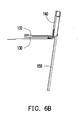
- FIG. 6A is a front view of the frames and other components of FIG. 3C .
- FIG. 6B is a side view of the frames and other components of FIG. 6A .
- FIGs. 1A to 1C are respectively perspective views of a portable electronic device in three appearance states according to an embodiment of the present invention
- FIGs. 2A to 2C are respectively perspective views of the portable electronic device of FIGs. 1A to 1C from another viewing angle
- FIGs. 3A to 3C are respectively perspective views of a plurality of components, including frames and other components, of the portable electronic device of FIGs. 2A to 2C .
- a portable electronic device 100 includes a first body 110 and a second body 120.
- the first body 110 has a first surface S 1 and a second surface S2 opposite to each other.
- the second body 120 is located on the first body 110 and covers the first surface S1.
- the portable electronic device 100 further includes a first frame 130, a second frame 140, and a third frame 150.
- the first frame 130 is fixed on the first body 110 of FIG. 2C .
- the second frame 140 is pivoted to the first frame 130.
- the third frame 150 is fixed on the second body 120 of FIG. 2C .
- the third frame 150 is slidably coupled to the second frame 140, as shown in FIGs. 3A and 3B .
- the second frame 140 is capable of sliding between a first position of FIG. 3A and a second position of FIG. 3B relative to the third frame 150, such that the second body 120 is capable of sliding between the positions of FIGs. 2A and 2B relative to the first body 110.
- the first frame 130 is capable of rotating towards the first position of FIG. 3A from the second position of FIG. 3B to reach a third position of FIG. 3C relative to the second frame 140, such that the second body 120 is capable of being turned over from the first surface S 1 to the second surface S2 relative to the first body 110, as shown in FIG. 2C .
- the second body 120 is capable of being turned over from the first surface S 1 to the second surface S2 relative to the first body 110, such that the portable electronic device 100 is provided with an additional appearance state, so that the applications of the portable electronic device 100 are further expanded when being used together with the software.
- FIG. 4 is a bottom view of the frames and other components of FIG. 3A
- FIG. 5A is a partial front view of the frames and other components of FIG. 3A
- a first limiting part 160 is represented by slashes here.
- the portable electronic device 100 further includes a first limiting part 160, connected to the second frame 140.
- the first limiting part 160 includes a first elastic portion 162 and a first limiting portion 164.
- the first elastic portion 162 is fixed on the second frame 140.
- the first limiting portion 164 extends from the first elastic portion 162.
- the first frame 130 has a stopping portion 134. Therefore, when the second frame 140 slides relative to the third frame 150, the first limiting part 160 interferes with the stopping portion 134, so as to limit the rotation of the first frame 130 relative to the second frame 140.
- FIG. 5B is a partial front view of the frames and other components of FIG. 3B .
- the third frame 150 has a first restraining part 152, and when the second frame 140 slides to the second position of FIG. 3B relative to the third frame 150, the first restraining part 152 releases the limiting effect of the first limiting part 160 on the rotation of the first frame 130.
- the first restraining part 152 pushes the first elastic portion 162, so as to release the interference relationship between the first limiting portion 164 and the stopping portion 134.
- FIG. 6A is a front view of the frames and other components of FIG. 3C
- FIG. 6B is a side view of the frames and other components of FIG. 6A
- the portable electronic device 100 further includes a second limiting part 170, connected to the second frame 140.
- the second limiting part 170 includes a second elastic portion 172 and a second limiting portion 174.
- the second elastic portion 172 is fixed on the second frame 140.
- the second limiting portion 174 extends from the second elastic portion 172.
- the third frame 150 has a snapping portion 154, which is also shown in FIG. 4 . Therefore, when the first frame 130 rotates relative to the second frame 140, the second limiting portion 174 interferes with the snapping portion 154, so as to limit the rotation of the second frame 140 relative to the third frame 150.
- the first frame 130 has a second restraining part 132.
- the second restraining part 132 releases the limitation effect of the second limiting part 170 on the sliding motion of the third frame 150.
- the second restraining part 132 pushes the second elastic portion 172, so as to release the interference relationship between the second limiting portion 174 and the snapping portion 154.
- the first frame 130 and the second frame 140 are attached to each other under a magnetic attraction force, such that the user can conveniently control the rotation of the first frame 130 relative to the second frame 140.
- the portable electronic device 100 further includes a magnetic part 180 arranged on the first frame 130, and the second frame 140 correspondingly has magnetic susceptibility, such that the first frame 130 is capable of being attached on the second frame 140.
- two magnetic parts are respectively arranged on the first frame 130 and the second frame 140, and the first frame 130 and the second frame 140 are attached to each other under the magnetic attraction force between the two magnetic parts.
- the portable electronic device 100 further includes a first driving part 190 connected between the first frame 130 and the second frame 140.
- the first driving part 190 is, for example, a torsion spring.
- the first driving part 190 is compressed.
- the first limiting part 160 releases the limiting relationship with the first frame 130, such that the first driving part 190 drives the first frame 130 and the second frame 140 to rotate relative to each other.
- an elastic force of the first driving part 190 is insufficient for separating the first frame 130 from the second frame 140.
- the elastic force of the first driving part 190 enables the portable electronic device 100 to maintain the state of FIG. 1C .
- the first body 110 has a keyboard 112 and a loudspeaker opening 114.
- the keyboard 112 is, for example, a QWERTY keyboard, and is located on the first surface S1.
- the loudspeaker opening 114 is located on the second surface S2.
- the loudspeaker opening 114 is located on the second surface S2 of the first body 110, when the second body 120 is located on a position of FIG. 2C relative to the first body 110, the loudspeaker opening 114 is exposed out of the first body 110. In this way, the sounds produced by a loudspeaker (not shown) configured within the portable electronic device 100 are transmitted from the loudspeaker opening 114 without being interfered, thereby achieving a desirable sound quality.
- the portable electronic device 100 further includes at least one second driving part 200 connected between the second frame 140 and the third frame 150.
- the second driving part 200 is, for example, a torsion spring or any other device capable of providing an elastic force.
- the second driving part 200 provides a driving force on the second frame 140 and the third frame 150, such that the second body 120 and the first body 110 can slide with respect to each other in a semi-auto sliding manner.
- the present invention provides an operation method, applicable to operate the portable electronic device 100, in which the structure of the portable electronic device 100 has already been described in the above embodiments, so it is not described here repeatedly.
- the operation method enables the portable electronic device 100 to have three different appearance states as follows.
- the second frame 140 is located on the first position of FIG. 3A relative to the third frame 150, such that the relative position between the second body 120 and the first body 110 is as shown in FIG. 1A , and the portable electronic device 100 enters a first operation mode.
- the second body 120 has a screen 122, which may be a touch screen. Therefore, the user can manipulate the portable electronic device 100 through the screen 122 in the first operation mode.
- the first operation mode includes a phone mode.
- the second frame 140 is located on the second position relative to the third frame 150, such that the relative position between the second body 120 and the first body 110 is as shown in FIG. 1B , and the portable electronic device 100 enters a second operation mode, including an input mode.
- the keyboard 112 is exposed out of the first body 110, such that the user can conveniently manipulate the portable electronic device 100 through the screen 122 and the keyboard 112.
- the first frame 130 is located on the third position relative to the second frame 140, such that the relative position between the second body 120 and the first body 110 is as shown in FIG. 1C , and the portable electronic device 100 enters a third operation mode, including a multimedia playing mode.
- the loudspeaker opening 114 (as shown in FIGs. 2A and 2B ) of the portable electronic device 100 is located on the second surface S2, such that the portable electronic device 100 can provide a high sound output quality when playing audio/video products.
- the angle of the screen 122 is also suitable for being viewed by the user, such that the third operation mode is suitable for playing audio/video products or holding video conferences.
- the second body is capable of sliding relative to the first body through the frames, and is capable of being turned over from the first surface of the first body to the second surface thereof relative to the first body. Therefore, as compared with the prior art, the portable electronic device in the above embodiments is further provided with an additional appearance state, so that the operation scope of the portable electronic device is further expanded when being used together with the software.
- the loudspeaker opening of the second body is located on the second surface, when the second body is turned over relative to the first body, and the portable electronic device enters the third operation mode (for example, multimedia playing mode), and is placed on the platform, the loudspeaker opening is exposed out of the second body and is not covered by the platform, such that the high sound output quality is maintained, and thus the third operation mode is suitable for playing audio/video products.
- the third operation mode for example, multimedia playing mode
Landscapes
- Engineering & Computer Science (AREA)
- Signal Processing (AREA)
- Telephone Set Structure (AREA)
- Casings For Electric Apparatus (AREA)
Applications Claiming Priority (1)
| Application Number | Priority Date | Filing Date | Title |
|---|---|---|---|
| TW098112681A TWI394516B (zh) | 2009-04-16 | 2009-04-16 | 可攜式電子裝置 |
Publications (2)
| Publication Number | Publication Date |
|---|---|
| EP2242237A1 true EP2242237A1 (fr) | 2010-10-20 |
| EP2242237B1 EP2242237B1 (fr) | 2011-08-24 |
Family
ID=42235673
Family Applications (1)
| Application Number | Title | Priority Date | Filing Date |
|---|---|---|---|
| EP10002527A Active EP2242237B1 (fr) | 2009-04-16 | 2010-03-10 | Dispositif électronique portable |
Country Status (5)
| Country | Link |
|---|---|
| US (1) | US8494602B2 (fr) |
| EP (1) | EP2242237B1 (fr) |
| JP (1) | JP3161052U (fr) |
| AT (1) | ATE522076T1 (fr) |
| TW (1) | TWI394516B (fr) |
Families Citing this family (33)
| Publication number | Priority date | Publication date | Assignee | Title |
|---|---|---|---|---|
| JP4638937B2 (ja) * | 2008-12-26 | 2011-02-23 | 三菱製鋼株式会社 | スライド型ヒンジ機構 |
| US8284554B2 (en) * | 2010-02-15 | 2012-10-09 | Motorola Mobility Llc | Electronic device housing with pivoting and sliding portions |
| TW201224713A (en) * | 2010-12-02 | 2012-06-16 | Compal Electronics Inc | Mobile electronic device |
| US8649166B2 (en) | 2011-01-11 | 2014-02-11 | Z124 | Multi-positionable portable computer |
| US8648821B2 (en) * | 2011-01-18 | 2014-02-11 | Flextronics Id, Llc | Spheroidal pivot for an electronic device |
| US9407984B2 (en) * | 2011-02-24 | 2016-08-02 | Htc Corporation | Method and apparatus for adjusting sound quality |
| US8526178B2 (en) | 2011-05-17 | 2013-09-03 | Flextronics Ap, Llc | All-in-one computing device with an adjustable screen height |
| CN102799230B (zh) * | 2011-05-26 | 2015-12-09 | 英华达(上海)科技有限公司 | 移动式产品承载装置 |
| US8681113B1 (en) | 2011-09-27 | 2014-03-25 | Flextronics Ap, Llc | Concept and operation mode for multi media AIO |
| USD742348S1 (en) * | 2013-02-12 | 2015-11-03 | Lg Electronics Inc. | Mobile phone |
| USD733087S1 (en) * | 2013-02-12 | 2015-06-30 | Lg Electronics Inc. | Mobile phone |
| JP1485872S (fr) * | 2013-05-10 | 2016-05-30 | ||
| TWI486746B (zh) * | 2013-09-05 | 2015-06-01 | Quanta Comp Inc | 電子裝置 |
| USD738343S1 (en) * | 2013-10-03 | 2015-09-08 | Sony Mobile Communications Ab | Mobile phone |
| USD749538S1 (en) * | 2013-10-04 | 2016-02-16 | Sony Mobile Communications Ab | Mobile phone |
| USD737795S1 (en) * | 2013-12-16 | 2015-09-01 | Sony Mobile Communications Ab | Mobile phone |
| USD740247S1 (en) * | 2014-02-13 | 2015-10-06 | Lg Electronics Inc. | Cellular phone |
| USD762626S1 (en) * | 2014-02-19 | 2016-08-02 | Lenovo (Beijing) Co., Ltd. | Electronic device |
| USD770411S1 (en) * | 2014-03-13 | 2016-11-01 | Hisense Mobile Communications Technology Co., Ltd. | Handset |
| USD738344S1 (en) * | 2014-03-14 | 2015-09-08 | Lg Electronics Inc. | Cellular phone |
| TWI508565B (zh) * | 2014-04-21 | 2015-11-11 | Pegatron Corp | 可攜式電子裝置 |
| USD764431S1 (en) * | 2014-05-09 | 2016-08-23 | Sony Mobile Communications Ab | Mobile phone |
| CN105491313A (zh) * | 2014-09-15 | 2016-04-13 | 鸿富锦精密工业(深圳)有限公司 | 显示装置及机芯结构 |
| USD772189S1 (en) * | 2014-11-10 | 2016-11-22 | Microsoft Mobile Oy | Handset |
| USD772190S1 (en) * | 2014-12-15 | 2016-11-22 | Microsoft Mobile Oy | Handset |
| USD773426S1 (en) * | 2015-01-12 | 2016-12-06 | Microsoft Corporation | Handset |
| USD778867S1 (en) * | 2015-02-27 | 2017-02-14 | Microsoft Corporation | Handset |
| USD778868S1 (en) * | 2015-03-19 | 2017-02-14 | Microsoft Corporation | Handset |
| USD778891S1 (en) * | 2015-03-31 | 2017-02-14 | Microsoft Corporation | Handset |
| USD811358S1 (en) * | 2015-05-21 | 2018-02-27 | Sony Mobile Communications Inc. | Mobile phone |
| USD786214S1 (en) * | 2015-08-27 | 2017-05-09 | Lg Display Co., Ltd. | Mobile phone |
| CN110417949A (zh) * | 2018-04-28 | 2019-11-05 | Oppo广东移动通信有限公司 | 移动终端 |
| USD898692S1 (en) * | 2019-02-12 | 2020-10-13 | Huizhou Tcl Mobile Communication Co., Ltd. | Slide phone |
Citations (3)
| Publication number | Priority date | Publication date | Assignee | Title |
|---|---|---|---|---|
| GB2434274A (en) | 2005-12-29 | 2007-07-18 | Motorola Inc | Portable device with operating mode dependent upon form-factor |
| EP1916826A1 (fr) | 2006-10-25 | 2008-04-30 | High Tech Computer Corp. | Dispositifs électroniques équipés de méchanismes coulissants et pivotants |
| WO2008066342A1 (fr) | 2006-12-01 | 2008-06-05 | Diabell Co., Ltd. | Appareil coulissant et terminal manuel équipé de l'appareil coulissant |
Family Cites Families (17)
| Publication number | Priority date | Publication date | Assignee | Title |
|---|---|---|---|---|
| US4156620A (en) * | 1974-07-18 | 1979-05-29 | Clemens George S | Apparatus and method for cleaning teeth |
| US4781704A (en) * | 1987-02-24 | 1988-11-01 | Entech, Inc. | Feeding tube assembly with collapsible outlet connector |
| US4930997A (en) * | 1987-08-19 | 1990-06-05 | Bennett Alan N | Portable medical suction device |
| US6734886B1 (en) * | 1999-12-21 | 2004-05-11 | Personalpath Systems, Inc. | Method of customizing a browsing experience on a world-wide-web site |
| US6618858B1 (en) * | 2000-05-11 | 2003-09-09 | At Home Liquidating Trust | Automatic identification of a set-top box user to a network |
| US7165221B2 (en) * | 2000-11-13 | 2007-01-16 | Draeger Medical Systems, Inc. | System and method for navigating patient medical information |
| JP4488339B2 (ja) * | 2001-07-31 | 2010-06-23 | スコット・ラボラトリーズ・インコーポレイテッド | Iv注入投与を行う装置 |
| US20040010425A1 (en) * | 2002-01-29 | 2004-01-15 | Wilkes Gordon J. | System and method for integrating clinical documentation with the point of care treatment of a patient |
| US20050251102A1 (en) * | 2003-09-26 | 2005-11-10 | Michael Hegland | Catheter connection systems and methods |
| US20050119534A1 (en) * | 2003-10-23 | 2005-06-02 | Pfizer, Inc. | Method for predicting the onset or change of a medical condition |
| US7388578B2 (en) * | 2004-07-01 | 2008-06-17 | Nokia Corporation | Touch display PDA phone with slide keypad |
| US8055511B2 (en) * | 2004-12-29 | 2011-11-08 | Cerner Innovation, Inc. | System and methods for providing medication selection guidance |
| JP4845558B2 (ja) | 2006-03-29 | 2011-12-28 | 加藤電機株式会社 | 携帯機器 |
| KR100833241B1 (ko) * | 2006-04-28 | 2008-05-28 | 삼성전자주식회사 | 슬라이딩-틸트장치 및 이를 채용한 모바일 기기 |
| TWI328957B (en) * | 2006-10-13 | 2010-08-11 | Htc Corp | Two-sectional track module, sliding-pivoting mechanism and portable electronic device using the same |
| TWI366378B (en) * | 2007-08-31 | 2012-06-11 | Asustek Comp Inc | A flip apparatus applied in electronic devices |
| US7986983B2 (en) * | 2007-12-28 | 2011-07-26 | Motorola Mobility, Inc. | Methods and slider form factor devices with continguous surfaces when open |
-
2009
- 2009-04-16 TW TW098112681A patent/TWI394516B/zh active
- 2009-12-04 US US12/630,851 patent/US8494602B2/en active Active
-
2010
- 2010-02-17 JP JP2010000969U patent/JP3161052U/ja not_active Expired - Lifetime
- 2010-03-10 AT AT10002527T patent/ATE522076T1/de not_active IP Right Cessation
- 2010-03-10 EP EP10002527A patent/EP2242237B1/fr active Active
Patent Citations (3)
| Publication number | Priority date | Publication date | Assignee | Title |
|---|---|---|---|---|
| GB2434274A (en) | 2005-12-29 | 2007-07-18 | Motorola Inc | Portable device with operating mode dependent upon form-factor |
| EP1916826A1 (fr) | 2006-10-25 | 2008-04-30 | High Tech Computer Corp. | Dispositifs électroniques équipés de méchanismes coulissants et pivotants |
| WO2008066342A1 (fr) | 2006-12-01 | 2008-06-05 | Diabell Co., Ltd. | Appareil coulissant et terminal manuel équipé de l'appareil coulissant |
Also Published As
| Publication number | Publication date |
|---|---|
| US20100267428A1 (en) | 2010-10-21 |
| ATE522076T1 (de) | 2011-09-15 |
| EP2242237B1 (fr) | 2011-08-24 |
| TW201039727A (en) | 2010-11-01 |
| TWI394516B (zh) | 2013-04-21 |
| US8494602B2 (en) | 2013-07-23 |
| JP3161052U (ja) | 2010-07-22 |
Similar Documents
| Publication | Publication Date | Title |
|---|---|---|
| US8494602B2 (en) | Portable electronic device | |
| CN101051847B (zh) | 便携式终端及其滑动支架 | |
| US7526325B2 (en) | Triple-axis rotation folder-type portable apparatus | |
| US7610067B2 (en) | Swing hinge module for portable communication device | |
| US7622685B2 (en) | Portable information terminal | |
| EP1806909B1 (fr) | Terminal de communication portable pour les jeux, et dispositif d'interface d'utilisateur correspondant | |
| US8032192B2 (en) | Portable terminal and sliding/swing-type cradling apparatus thereof | |
| US20050266897A1 (en) | Sliding/folding-type portable apparatus | |
| KR100800769B1 (ko) | 멀티미디어 휴대 통신 장치 | |
| EP2432197B1 (fr) | Dispositif électronique portable et retractable avec pied pivotable | |
| EP1928158A1 (fr) | Téléphone mobile pour multimédia avec fonction de berceau | |
| CN101873771B (zh) | 可携式电子装置 | |
| US8275425B2 (en) | Portable terminal for multimedia | |
| KR100800711B1 (ko) | 휴대 단말기의 프리 스톱 힌지 장치 | |
| KR100876790B1 (ko) | 멀티미디어 휴대 통신 장치 | |
| US7729492B2 (en) | Portable communication device having a multi-axis hinge assembly | |
| KR100790187B1 (ko) | 게임 겸용 휴대 통신 단말기의 힌지 장치 | |
| EP1594291B1 (fr) | Dispositif portable repliable coulissant | |
| JP2005076688A (ja) | スライド機能を有する折畳み型携帯端末 | |
| KR100800753B1 (ko) | 양면 사용 슬라이딩 타입 휴대 단말기 | |
| KR100790169B1 (ko) | 휴대용 단말기의 스윙 힌지 장치 | |
| KR100895187B1 (ko) | 게임 겸용 휴대용 전자 장치 | |
| KR20080041504A (ko) | 멀티 모드 구조 및 이 구조를 사용한 멀티미디어 장치 | |
| KR20080044428A (ko) | 휴대 통신 단말기 | |
| WO2007129470A1 (fr) | Dispositif de terminal d'informations portable |
Legal Events
| Date | Code | Title | Description |
|---|---|---|---|
| PUAI | Public reference made under article 153(3) epc to a published international application that has entered the european phase |
Free format text: ORIGINAL CODE: 0009012 |
|
| 17P | Request for examination filed |
Effective date: 20100310 |
|
| AK | Designated contracting states |
Kind code of ref document: A1 Designated state(s): AT BE BG CH CY CZ DE DK EE ES FI FR GB GR HR HU IE IS IT LI LT LU LV MC MK MT NL NO PL PT RO SE SI SK SM TR |
|
| AX | Request for extension of the european patent |
Extension state: AL BA ME RS |
|
| RIC1 | Information provided on ipc code assigned before grant |
Ipc: H04M 1/02 20060101AFI20110203BHEP |
|
| GRAP | Despatch of communication of intention to grant a patent |
Free format text: ORIGINAL CODE: EPIDOSNIGR1 |
|
| GRAS | Grant fee paid |
Free format text: ORIGINAL CODE: EPIDOSNIGR3 |
|
| GRAA | (expected) grant |
Free format text: ORIGINAL CODE: 0009210 |
|
| AK | Designated contracting states |
Kind code of ref document: B1 Designated state(s): AT BE BG CH CY CZ DE DK EE ES FI FR GB GR HR HU IE IS IT LI LT LU LV MC MK MT NL NO PL PT RO SE SI SK SM TR |
|
| REG | Reference to a national code |
Ref country code: GB Ref legal event code: FG4D |
|
| REG | Reference to a national code |
Ref country code: CH Ref legal event code: EP |
|
| REG | Reference to a national code |
Ref country code: IE Ref legal event code: FG4D |
|
| REG | Reference to a national code |
Ref country code: NL Ref legal event code: T3 |
|
| REG | Reference to a national code |
Ref country code: DE Ref legal event code: R096 Ref document number: 602010000147 Country of ref document: DE Effective date: 20111020 |
|
| LTIE | Lt: invalidation of european patent or patent extension |
Effective date: 20110824 |
|
| PG25 | Lapsed in a contracting state [announced via postgrant information from national office to epo] |
Ref country code: FI Free format text: LAPSE BECAUSE OF FAILURE TO SUBMIT A TRANSLATION OF THE DESCRIPTION OR TO PAY THE FEE WITHIN THE PRESCRIBED TIME-LIMIT Effective date: 20110824 Ref country code: LT Free format text: LAPSE BECAUSE OF FAILURE TO SUBMIT A TRANSLATION OF THE DESCRIPTION OR TO PAY THE FEE WITHIN THE PRESCRIBED TIME-LIMIT Effective date: 20110824 Ref country code: HR Free format text: LAPSE BECAUSE OF FAILURE TO SUBMIT A TRANSLATION OF THE DESCRIPTION OR TO PAY THE FEE WITHIN THE PRESCRIBED TIME-LIMIT Effective date: 20110824 Ref country code: NO Free format text: LAPSE BECAUSE OF FAILURE TO SUBMIT A TRANSLATION OF THE DESCRIPTION OR TO PAY THE FEE WITHIN THE PRESCRIBED TIME-LIMIT Effective date: 20111124 Ref country code: SE Free format text: LAPSE BECAUSE OF FAILURE TO SUBMIT A TRANSLATION OF THE DESCRIPTION OR TO PAY THE FEE WITHIN THE PRESCRIBED TIME-LIMIT Effective date: 20110824 Ref country code: IS Free format text: LAPSE BECAUSE OF FAILURE TO SUBMIT A TRANSLATION OF THE DESCRIPTION OR TO PAY THE FEE WITHIN THE PRESCRIBED TIME-LIMIT Effective date: 20111224 Ref country code: PT Free format text: LAPSE BECAUSE OF FAILURE TO SUBMIT A TRANSLATION OF THE DESCRIPTION OR TO PAY THE FEE WITHIN THE PRESCRIBED TIME-LIMIT Effective date: 20111226 |
|
| REG | Reference to a national code |
Ref country code: AT Ref legal event code: MK05 Ref document number: 522076 Country of ref document: AT Kind code of ref document: T Effective date: 20110824 |
|
| PG25 | Lapsed in a contracting state [announced via postgrant information from national office to epo] |
Ref country code: PL Free format text: LAPSE BECAUSE OF FAILURE TO SUBMIT A TRANSLATION OF THE DESCRIPTION OR TO PAY THE FEE WITHIN THE PRESCRIBED TIME-LIMIT Effective date: 20110824 Ref country code: GR Free format text: LAPSE BECAUSE OF FAILURE TO SUBMIT A TRANSLATION OF THE DESCRIPTION OR TO PAY THE FEE WITHIN THE PRESCRIBED TIME-LIMIT Effective date: 20111125 Ref country code: SI Free format text: LAPSE BECAUSE OF FAILURE TO SUBMIT A TRANSLATION OF THE DESCRIPTION OR TO PAY THE FEE WITHIN THE PRESCRIBED TIME-LIMIT Effective date: 20110824 Ref country code: AT Free format text: LAPSE BECAUSE OF FAILURE TO SUBMIT A TRANSLATION OF THE DESCRIPTION OR TO PAY THE FEE WITHIN THE PRESCRIBED TIME-LIMIT Effective date: 20110824 Ref country code: LV Free format text: LAPSE BECAUSE OF FAILURE TO SUBMIT A TRANSLATION OF THE DESCRIPTION OR TO PAY THE FEE WITHIN THE PRESCRIBED TIME-LIMIT Effective date: 20110824 Ref country code: CY Free format text: LAPSE BECAUSE OF FAILURE TO SUBMIT A TRANSLATION OF THE DESCRIPTION OR TO PAY THE FEE WITHIN THE PRESCRIBED TIME-LIMIT Effective date: 20110824 |
|
| PG25 | Lapsed in a contracting state [announced via postgrant information from national office to epo] |
Ref country code: BE Free format text: LAPSE BECAUSE OF FAILURE TO SUBMIT A TRANSLATION OF THE DESCRIPTION OR TO PAY THE FEE WITHIN THE PRESCRIBED TIME-LIMIT Effective date: 20110824 |
|
| PG25 | Lapsed in a contracting state [announced via postgrant information from national office to epo] |
Ref country code: SK Free format text: LAPSE BECAUSE OF FAILURE TO SUBMIT A TRANSLATION OF THE DESCRIPTION OR TO PAY THE FEE WITHIN THE PRESCRIBED TIME-LIMIT Effective date: 20110824 Ref country code: CZ Free format text: LAPSE BECAUSE OF FAILURE TO SUBMIT A TRANSLATION OF THE DESCRIPTION OR TO PAY THE FEE WITHIN THE PRESCRIBED TIME-LIMIT Effective date: 20110824 |
|
| PG25 | Lapsed in a contracting state [announced via postgrant information from national office to epo] |
Ref country code: EE Free format text: LAPSE BECAUSE OF FAILURE TO SUBMIT A TRANSLATION OF THE DESCRIPTION OR TO PAY THE FEE WITHIN THE PRESCRIBED TIME-LIMIT Effective date: 20110824 Ref country code: IT Free format text: LAPSE BECAUSE OF FAILURE TO SUBMIT A TRANSLATION OF THE DESCRIPTION OR TO PAY THE FEE WITHIN THE PRESCRIBED TIME-LIMIT Effective date: 20110824 Ref country code: RO Free format text: LAPSE BECAUSE OF FAILURE TO SUBMIT A TRANSLATION OF THE DESCRIPTION OR TO PAY THE FEE WITHIN THE PRESCRIBED TIME-LIMIT Effective date: 20110824 |
|
| PG25 | Lapsed in a contracting state [announced via postgrant information from national office to epo] |
Ref country code: DK Free format text: LAPSE BECAUSE OF FAILURE TO SUBMIT A TRANSLATION OF THE DESCRIPTION OR TO PAY THE FEE WITHIN THE PRESCRIBED TIME-LIMIT Effective date: 20110824 |
|
| PLBE | No opposition filed within time limit |
Free format text: ORIGINAL CODE: 0009261 |
|
| STAA | Information on the status of an ep patent application or granted ep patent |
Free format text: STATUS: NO OPPOSITION FILED WITHIN TIME LIMIT |
|
| 26N | No opposition filed |
Effective date: 20120525 |
|
| REG | Reference to a national code |
Ref country code: DE Ref legal event code: R097 Ref document number: 602010000147 Country of ref document: DE Effective date: 20120525 |
|
| PG25 | Lapsed in a contracting state [announced via postgrant information from national office to epo] |
Ref country code: MC Free format text: LAPSE BECAUSE OF NON-PAYMENT OF DUE FEES Effective date: 20120331 |
|
| REG | Reference to a national code |
Ref country code: IE Ref legal event code: MM4A |
|
| PG25 | Lapsed in a contracting state [announced via postgrant information from national office to epo] |
Ref country code: IE Free format text: LAPSE BECAUSE OF NON-PAYMENT OF DUE FEES Effective date: 20120310 |
|
| PG25 | Lapsed in a contracting state [announced via postgrant information from national office to epo] |
Ref country code: MK Free format text: LAPSE BECAUSE OF FAILURE TO SUBMIT A TRANSLATION OF THE DESCRIPTION OR TO PAY THE FEE WITHIN THE PRESCRIBED TIME-LIMIT Effective date: 20110824 |
|
| PG25 | Lapsed in a contracting state [announced via postgrant information from national office to epo] |
Ref country code: ES Free format text: LAPSE BECAUSE OF FAILURE TO SUBMIT A TRANSLATION OF THE DESCRIPTION OR TO PAY THE FEE WITHIN THE PRESCRIBED TIME-LIMIT Effective date: 20111205 |
|
| PG25 | Lapsed in a contracting state [announced via postgrant information from national office to epo] |
Ref country code: BG Free format text: LAPSE BECAUSE OF FAILURE TO SUBMIT A TRANSLATION OF THE DESCRIPTION OR TO PAY THE FEE WITHIN THE PRESCRIBED TIME-LIMIT Effective date: 20111124 |
|
| PG25 | Lapsed in a contracting state [announced via postgrant information from national office to epo] |
Ref country code: MT Free format text: LAPSE BECAUSE OF FAILURE TO SUBMIT A TRANSLATION OF THE DESCRIPTION OR TO PAY THE FEE WITHIN THE PRESCRIBED TIME-LIMIT Effective date: 20110824 |
|
| PG25 | Lapsed in a contracting state [announced via postgrant information from national office to epo] |
Ref country code: TR Free format text: LAPSE BECAUSE OF FAILURE TO SUBMIT A TRANSLATION OF THE DESCRIPTION OR TO PAY THE FEE WITHIN THE PRESCRIBED TIME-LIMIT Effective date: 20110824 |
|
| PG25 | Lapsed in a contracting state [announced via postgrant information from national office to epo] |
Ref country code: LU Free format text: LAPSE BECAUSE OF NON-PAYMENT OF DUE FEES Effective date: 20120310 Ref country code: SM Free format text: LAPSE BECAUSE OF FAILURE TO SUBMIT A TRANSLATION OF THE DESCRIPTION OR TO PAY THE FEE WITHIN THE PRESCRIBED TIME-LIMIT Effective date: 20110824 |
|
| PG25 | Lapsed in a contracting state [announced via postgrant information from national office to epo] |
Ref country code: HU Free format text: LAPSE BECAUSE OF FAILURE TO SUBMIT A TRANSLATION OF THE DESCRIPTION OR TO PAY THE FEE WITHIN THE PRESCRIBED TIME-LIMIT Effective date: 20100310 |
|
| REG | Reference to a national code |
Ref country code: CH Ref legal event code: PL |
|
| PG25 | Lapsed in a contracting state [announced via postgrant information from national office to epo] |
Ref country code: LI Free format text: LAPSE BECAUSE OF NON-PAYMENT OF DUE FEES Effective date: 20140331 Ref country code: CH Free format text: LAPSE BECAUSE OF NON-PAYMENT OF DUE FEES Effective date: 20140331 |
|
| REG | Reference to a national code |
Ref country code: FR Ref legal event code: PLFP Year of fee payment: 7 |
|
| REG | Reference to a national code |
Ref country code: FR Ref legal event code: PLFP Year of fee payment: 8 |
|
| REG | Reference to a national code |
Ref country code: FR Ref legal event code: PLFP Year of fee payment: 9 |
|
| PGFP | Annual fee paid to national office [announced via postgrant information from national office to epo] |
Ref country code: FR Payment date: 20230110 Year of fee payment: 14 |
|
| P01 | Opt-out of the competence of the unified patent court (upc) registered |
Effective date: 20230602 |
|
| PGFP | Annual fee paid to national office [announced via postgrant information from national office to epo] |
Ref country code: NL Payment date: 20240108 Year of fee payment: 15 |
|
| PGFP | Annual fee paid to national office [announced via postgrant information from national office to epo] |
Ref country code: DE Payment date: 20231229 Year of fee payment: 15 Ref country code: GB Payment date: 20240108 Year of fee payment: 15 |