EP2242197A1 - Mobilkommunikationssystem, empfangsgerät und verfahren dafür - Google Patents
Mobilkommunikationssystem, empfangsgerät und verfahren dafür Download PDFInfo
- Publication number
- EP2242197A1 EP2242197A1 EP09707309A EP09707309A EP2242197A1 EP 2242197 A1 EP2242197 A1 EP 2242197A1 EP 09707309 A EP09707309 A EP 09707309A EP 09707309 A EP09707309 A EP 09707309A EP 2242197 A1 EP2242197 A1 EP 2242197A1
- Authority
- EP
- European Patent Office
- Prior art keywords
- matrix
- symbols
- subcarriers
- fourier
- signal
- Prior art date
- Legal status (The legal status is an assumption and is not a legal conclusion. Google has not performed a legal analysis and makes no representation as to the accuracy of the status listed.)
- Withdrawn
Links
Images


Classifications
-
- H—ELECTRICITY
- H04—ELECTRIC COMMUNICATION TECHNIQUE
- H04B—TRANSMISSION
- H04B7/00—Radio transmission systems, i.e. using radiation field
- H04B7/02—Diversity systems; Multi-antenna system, i.e. transmission or reception using multiple antennas
- H04B7/04—Diversity systems; Multi-antenna system, i.e. transmission or reception using multiple antennas using two or more spaced independent antennas
- H04B7/0413—MIMO systems
-
- H—ELECTRICITY
- H04—ELECTRIC COMMUNICATION TECHNIQUE
- H04J—MULTIPLEX COMMUNICATION
- H04J11/00—Orthogonal multiplex systems, e.g. using WALSH codes
- H04J11/0023—Interference mitigation or co-ordination
- H04J11/0026—Interference mitigation or co-ordination of multi-user interference
- H04J11/0036—Interference mitigation or co-ordination of multi-user interference at the receiver
- H04J11/0046—Interference mitigation or co-ordination of multi-user interference at the receiver using joint detection algorithms
-
- H—ELECTRICITY
- H04—ELECTRIC COMMUNICATION TECHNIQUE
- H04L—TRANSMISSION OF DIGITAL INFORMATION, e.g. TELEGRAPHIC COMMUNICATION
- H04L25/00—Baseband systems
- H04L25/02—Details ; arrangements for supplying electrical power along data transmission lines
- H04L25/03—Shaping networks in transmitter or receiver, e.g. adaptive shaping networks
- H04L25/03006—Arrangements for removing intersymbol interference
- H04L25/03159—Arrangements for removing intersymbol interference operating in the frequency domain
-
- H—ELECTRICITY
- H04—ELECTRIC COMMUNICATION TECHNIQUE
- H04L—TRANSMISSION OF DIGITAL INFORMATION, e.g. TELEGRAPHIC COMMUNICATION
- H04L25/00—Baseband systems
- H04L25/02—Details ; arrangements for supplying electrical power along data transmission lines
- H04L25/03—Shaping networks in transmitter or receiver, e.g. adaptive shaping networks
- H04L25/03006—Arrangements for removing intersymbol interference
- H04L25/03178—Arrangements involving sequence estimation techniques
- H04L25/03203—Trellis search techniques
- H04L25/03216—Trellis search techniques using the M-algorithm
-
- H—ELECTRICITY
- H04—ELECTRIC COMMUNICATION TECHNIQUE
- H04L—TRANSMISSION OF DIGITAL INFORMATION, e.g. TELEGRAPHIC COMMUNICATION
- H04L25/00—Baseband systems
- H04L25/02—Details ; arrangements for supplying electrical power along data transmission lines
- H04L25/03—Shaping networks in transmitter or receiver, e.g. adaptive shaping networks
- H04L25/03891—Spatial equalizers
-
- H—ELECTRICITY
- H04—ELECTRIC COMMUNICATION TECHNIQUE
- H04L—TRANSMISSION OF DIGITAL INFORMATION, e.g. TELEGRAPHIC COMMUNICATION
- H04L27/00—Modulated-carrier systems
- H04L27/26—Systems using multi-frequency codes
- H04L27/2601—Multicarrier modulation systems
- H04L27/2647—Arrangements specific to the receiver only
Definitions
- the present invention generally relates to mobile communication technologies. More particularly, the present invention relates to a mobile communication system, a receiving device, and a method adapted for single-carrier multiple input multiple output (MIMO) transmission.
- MIMO single-carrier multiple input multiple output
- a frequency band is divided into multiple narrow frequency bands (subcarriers) and separate signals are transmitted using the subcarriers.
- subcarriers are arranged such that they become orthogonal to each other to improve frequency efficiency and to achieve high-speed, high-volume communications.
- OFDMA makes it possible to effectively reduce inter-subcarrier interference. This in turn makes it possible to concurrently transmit signals using subcarriers and to increase the symbol length. Also with OFDMA, it is possible to effectively reduce multipath interference by using a relatively long guard interval.
- PAPR peak-to-average power ratio
- single-carrier transmission schemes have an advantage in terms of reducing the PAPR.
- single-carrier transmission schemes such as single-carrier frequency division multiple access (SC-FDMA) and discrete Fourier transform (DFT) spread OFDM also make it possible to efficiently use a wide frequency band.
- SC-FDMA single-carrier frequency division multiple access
- DFT discrete Fourier transform
- a transmission signal is Fourier-transformed and mapped to subcarriers, and the mapped signal is inverse-Fourier-transformed and wirelessly transmitted.
- a received signal is Fourier-transformed, signal components mapped to the subcarriers are extracted, and transmission symbols are estimated.
- Such single-carrier transmission schemes are preferable in terms of efficiently using a frequency band while reducing the PAPR.
- Multipath interference increases as the transmission rate increases. For example, multipath interference becomes particularly prominent when the data modulation level is high or a MIMO multiplexing scheme is used. Increase in multipath interference in turn reduces the detection accuracy of signals at the receiving end.
- the number of transmitting antennas is N
- the expected number of multipaths is P
- a maximum likelihood detection (MLD) method is used for signal detection (for a QRM-MLD method, see, for example, K. J. Kim, et al., "Joint channel estimation and data detection algorithm for MIMO-OFDM systems", Proc. 36th Asilomar Conference on Signals, Systems and Computers, Nov. 2002 ).
- MLD maximum likelihood detection
- OFDMA makes it possible to effectively reduce inter-subcarrier interference and to sufficiently reduce multipath interference within a guard interval. Therefore, with OFDMA, the total number of symbol candidates that need to be examined at the receiving end is represented by the following formula: 2 N ⁇ B
- One object of the present invention is to improve the signal detection accuracy at a receiving end in a mobile communication system employing a single-carrier MIMO scheme and SC-FDMA.
- An aspect of the present invention provides a mobile communication system employing a single-carrier MIMO transmission scheme and including a transmitting device and a receiving device.
- the transmitting device includes a mapping unit configured to map Fourier-transformed and weighted symbols in a transmission symbol sequence to subcarriers, an inverse Fourier transform unit configured to inverse-Fourier-transform the mapped symbols, and a transmitting unit configured to transmit a signal including the inverse-Fourier-transformed symbols from multiple transmitting antennas.
- the receiving device includes an extracting unit configured to Fourier-transform signals received by multiple receiving antennas and to extract signal components mapped to the subcarriers from the signals, and a signal detection unit configured to estimate the symbols transmitted via the subcarriers by applying a QR decomposition algorithm to the extracted signal components.
- the signal detection unit includes a decomposition unit configured to obtain a unitary matrix such that the product of the unitary matrix, a weight matrix determining a correspondence between the transmission symbol sequence and the subcarriers, and a channel matrix indicating radio channel conditions between the transmitting antennas and the receiving antennas becomes a triangular matrix; and an estimation unit configured to estimate candidates of the symbols transmitted from the transmitting antennas based on the triangular matrix and a vector obtained by multiplying a received vector, which includes the signal components received by the receiving antennas, by the unitary matrix.
- An aspect of the present invention makes it possible to improve the signal detection accuracy at a receiving end in a mobile communication system employing a single-carrier MIMO scheme and SC-FDMA.
- An aspect of the present invention provides a receiving device for a mobile communication system employing a single-carrier MIMO transmission scheme and SC-FDMA.
- the receiving device includes an extracting unit configured to Fourier-transform signals received by multiple receiving antennas and to extract signal components mapped to subcarriers from the signals, and a signal detection unit configured to estimate symbols transmitted via the subcarriers by applying a QR decomposition algorithm to the extracted signal components.
- the signal detection unit includes a decomposition unit configured to obtain a unitary matrix Q H such that the product of the unitary matrix Q H , a weight matrix W determining a correspondence between a transmission symbol sequence and the subcarriers, and a channel matrix H indicating radio channel conditions between transmitting antennas and the receiving antennas becomes a triangular matrix R; and an estimation unit configured to estimate candidates x of the symbols transmitted from the transmitting antennas based on the triangular matrix R and a vector obtained by multiplying a received vector Y, which includes the signal components received by the receiving antennas, by the unitary matrix Q H .
- Using a Q R decomposition algorithm at the receiving end in a mobile communication system employing a single-carrier MIMO scheme makes it possible to reduce the computational complexity in signal detection as well as to improve the signal detection accuracy. Improved signal detection accuracy in turn makes it possible to reduce transmission power necessary to maintain desired quality. This approach is particularly preferable when the transmitting end is a user device.
- Using a QR decomposition algorithm also makes it possible to efficiently perform an equalization process in the frequency domain and a signal separation process based on, for example, MLD.
- the signal detection unit may further include a determining unit configured to calculate metrics for the respective candidates of the symbols and to narrow down the candidates based on the metrics.
- the metrics may indicate square Euclidean distances on a symbol constellation between received symbols and the candidates of the symbols.
- the receiving device may further include a permutation control unit configured to input a control signal for permuting rows or columns of a matrix product of the channel matrix and the weight matrix to the decomposition unit.
- the decomposition unit may be configured to obtain the triangular matrix and the unitary matrix such that the product of the triangular matrix and the unitary matrix equals the matrix product the rows or the columns of which are permuted according to the control signal.
- the permutation control unit may be configured to generate the control signal such that when the estimation unit estimates the symbols according to an M algorithm, the symbols from one of the transmitting antennas corresponding to higher received power are estimated prior to the symbols from another one of the transmitting antennas corresponding to lower received power.
- the permutation control unit may be configured to generate the control signal such that the estimation unit estimates a first subcarrier component of the symbols transmitted from a first one of the transmitting antennas and then estimates a first subcarrier component of the symbols transmitted from a second one of the transmitting antennas.
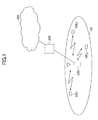
- FIG. 1 shows a mobile communication system according to an embodiment of the present invention.
- the mobile communication system includes a cell 50, user devices 100 1 , 100 2 , and 100 3 (may be collectively called the user device 100) in the cell 50, a base station 200, an access gateway 300, and a core network 400.
- the user devices 100 1 , 100 2 , and 100 3 perform radio communications with the base station 200 according to a MIMO scheme.
- the user device 100 is typically a mobile station, but may instead be implemented as a fixed station.
- the mobile communication system employs SC-FDMA (or DFT-spread OFDM) for uplink.
- the mobile communication system may employ SC-FDMA for downlink.
- FIG. 2 shows a transmitting device for the mobile communication system of this embodiment.
- the transmitting device is included in the user device 100.
- the transmitting device may be included in the base station 200.
- the transmitting device includes a discrete Fourier transform unit (DFT) 21, a frequency domain mapper 22, an inverse fast Fourier transform unit (IFFT) 23, and a guard interval adding unit (+CP) 24.
- DFT discrete Fourier transform unit
- IFFT inverse fast Fourier transform unit
- (+CP guard interval adding unit
- the discrete Fourier transform unit (DFT) 21 receives a symbol sequence to be transmitted and discrete-Fourier-transforms a predetermined number of symbols at once.
- the symbol sequence is typically, but is not limited to, a series of error-correction-coded and data-modulated symbols.
- the discrete Fourier transform unit (DFT) 21 discrete-Fourier-transforms a predetermined number (N DFT ) of symbols at once, and thereby transforms the symbol sequence in the time domain into a signal in the frequency domain.
- N DFT indicates a window size or a block size for discrete Fourier transformation.
- FIG. 3 is a drawing illustrating calculations performed by the DFT 21.
- x 1 at the left end indicates a signal (symbol sequence) to be transmitted from a first transmitting antenna of N TX transmitting antennas.
- Signals x 2 , x 3 ..., x NTX to be transmitted from second, third, ..., N TX transmitting antennas are omitted in FIG. 3 for brevity.
- the symbol sequence x 1 indicates N DFT symbols collectively.
- the symbol sequence x 1 includes N DFT symbols associated with a point on a symbol constellation. Discrete Fourier transformation is equivalent to weighted addition of the N DFT symbols. As shown in FIG.
- a second subcarrier signal w 2 ⁇ x 1 and subsequent subcarrier signals to be mapped to the corresponding subcarriers are obtained.
- the frequency domain mapper 22 shown in FIG. 2 maps the discrete-Fourier-transformed symbols to the corresponding subcarriers. For example, when frequency scheduling is performed for uplink, the frequency domain mapper 22 maps the symbols to available resource units. The available resource units are specified, for example, by scheduling information included in control information received by the transmitting device. Any appropriate method may be used for mapping the symbols to subcarriers. The simplest way may be to map the discrete-Fourier-transformed N DFT symbols to N DFT subcarriers from lower to higher frequencies.
- the inverse fast Fourier transform unit (IFFT) 23 inverse-fast-Fourier-transforms the symbols mapped to the subcarriers to transform the signal in the frequency domain into a signal (transmission symbols) in the time domain.
- the guard interval adding unit (+CP) 24 attaches guard intervals to the transmission symbols and outputs the transmission symbols with the guard intervals to a transmission signal generating unit (not shown) that follows.
- the guard intervals may be generated by a cyclic prefix (CP) scheme.
- FIG. 4 shows a receiving device for the mobile communication system of this embodiment.
- the receiving device includes a guard interval removing unit (-CP) 41, a fast Fourier transform unit (FFT) 42, a frequency domain demapper 43, and a signal detection unit 44.
- -CP guard interval removing unit
- FFT fast Fourier transform unit
- the guard interval removing unit (-CP) 41 removes guard intervals from a received baseband signal.
- the fast Fourier transform unit (FFT) 42 fast-Fourier-transforms the received signal and thereby transforms the received signal in the time domain into a signal in the frequency domain.
- the frequency domain demapper 43 performs a process, which is complementary to the process of the frequency domain mapper 22 of the transmitting device, on the signal in the frequency domain and thereby extracts signal components mapped to subcarriers.
- the signal detection unit 44 narrows down candidates of transmission symbols based on the signal components mapped to the subcarriers and identifies the transmission symbols.
- a transmission symbol sequence to be input to the DFT 21 and transmitted from an n-th transmitting antenna of the transmitting device of FIG. 2 is indicated by x n .
- the transmission symbol sequence x n includes N DFT symbols.
- N DFT indicates a window size (or a block size) for discrete Fourier transformation.
- x n x n ⁇ 1 x n ⁇ 2 ... x nNDFT T
- T indicates transposition
- n indicates a natural number less than or equal to N TX
- N TX indicates the total number of transmitting antennas.
- the received signals y i of the i-th subcarrier may be represented by the following formula:
- H i indicates a channel matrix indicating radio channel conditions regarding the i-th subcarrier.
- the channel matrix H i may be represented by the following formula:
- the channel matrix H i has dimensions of N RX rows and N TX columns.
- N RX indicates the total number of receiving antennas and N TX indicates the total number of transmitting antennas.
- a matrix element h i,pq of the channel matrix H i indicates one of channel conditions (transfer functions), which corresponds to the i-th subcarrier, between a p-th receiving antenna and a q-th transmitting antenna.
- Matrix elements of the channel matrix H i may be obtained, for example, based on reception conditions of a pilot signal.
- w i is a vector representing the weighting factors described above
- 0 NDFT is a 0 vector having N DFT elements.
- x n indicates a signal transmitted from an n-th transmitting antenna.
- N i indicates a noise component regarding the i-th subcarrier.
- Signals represented by formula (1) are input to the signal detection unit 44 of FIG. 4 .
- H ⁇ W Q ⁇ R
- the M-th signal component x M can be fairly easily estimated without taking into account the interference of signals of other subcarriers and/or other transmitting antennas.
- candidates of transmission symbols of the signal component x M are narrowed down based on formula (5).
- the signal component x M corresponds to a signal point on the symbol constellation.
- the smallest S1 (S1 ⁇ C) candidates are selected and other candidates are discarded.
- C indicates the total number of signal points (total number of possible candidates) in the symbol constellation.
- the S1 candidates obtained in the first stage are substituted for x M . There are also C candidates in total for x M-1 . Therefore, survival metrics are calculated as in the first stage for all combinations (S1 ⁇ C) of x M and x M -1.
- e ⁇ 2 ⁇ s M x , s M - 1 x z M - 1 - r M - 1 ⁇ M - 1 ⁇ s M - 1 x + r M - 1 ⁇ M ⁇ s M x 2 + e ⁇ 1 x
- the second term in the right-hand side of (8) indicates the survival metrics obtained in the first stage.
- survival metrics e2(s M (x),s M-1 (x) the survival metrics obtained in the first stage.
- S2 ⁇ S1C the survival metrics obtained in the first stage.
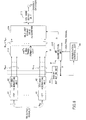
- FIG. 5 shows details of the signal detection unit 44 of FIG. 4 which mainly performs the process as described in ⁇ 4. OPERATIONS>.
- the signal detection unit 44 includes a QR decomposition unit 210, a signal transformation unit 212, a maximum likelihood detection (MLD) unit 214, and a likelihood output unit 215.
- the maximum likelihood detection unit 214 includes four determining units 216-1, 216-2, 216-3, and 216-4. For brevity, only four determining units are shown in FIG. 5 . However, any number of determining units may be provided depending on the number of transmission signals.
- the determining units 216-1, 216-2, 216-3, and 216-4 include substantially the same processing blocks, and therefore the determining unit 216-4 is taken as an example for the descriptions below.
- the determining unit 216-4 includes a symbol replica generating unit 218-4, a square Euclidean distance calculation unit 220-4, and a surviving symbol candidate selecting unit 222-4.
- FIG. 5 and other figures may be implemented by hardware, software, or a combination of them.
- the signal transformation unit 212 multiplies a vector Y including multiple received signals as elements by a conjugate transposed matrix Q H of the unitary matrix Q to transform the received signals.
- the unitary-transformed received signals can be expressed by the product of the upper triangular matrix R and a transmission symbol sequence x.
- the maximum likelihood detection unit 214 narrows down symbol candidates of transmission signals by a maximum likelihood detection (MLD) method.
- the symbol replica generating unit 218-4 of the determining unit 216-4 generates symbol candidates of a transmission signal corresponding to a received signal x 4 by using matrix elements of the upper triangular matrix R.
- the number of symbol candidates is represented by C.
- the square Euclidean distance calculation unit 220-4 calculates square Euclidean distances between a unitary-transformed received signal z i and C symbol candidates.
- the square Euclidean distances represent survival metrics used for calculations of likelihood.
- the surviving symbol candidate selecting unit 222-4 selects S1 ( ⁇ C) symbol candidates based on the square Euclidean distances and outputs the selected symbol candidates as surviving symbol candidates.
- the likelihood output unit 215 calculates the likelihood of symbol candidates output from the surviving symbol candidate selecting unit of the last stage. For example, the likelihood is represented by a log likelihood ratio (LLR).
- LLR log likelihood ratio
- An output from the likelihood output unit 215 indicates signal separation results and is sent to a demodulation unit (e.g., turbo decoder) that follows.
- the present invention is not limited to the above embodiment.
- No indicates average noise power measured at the receiving device
- I indicates a unit matrix of N TX rows and N TX columns.
- the unitary matrix Q has dimensions of N DFT (N TX +N RX ) rows and (N DFT ⁇ N TX ) columns.
- the upper triangular matrix R is a square matrix of (N DET ⁇ N TX ) rows and (N DFT ⁇ N TX ) columns, i.e., has the same dimensions as in the above embodiment.
- the received signals Y are represented by a vector of (N DFT ⁇ N RX ) rows and one column. Meanwhile, in this variation, the received signals Y' are represented by a vector of (N DFT ⁇ (N TX +N RX )) rows and one column where N DFT +N TX components are zeros.
- modified received signal vector Y' and the matrix G is preferable when performing MMSE QR decomposition or ZF QR decomposition.
- H indicates a channel matrix
- W indicates a weight matrix representing weighting in the frequency direction performed by the DFT 21
- F indicates the matrix product of the channel matrix H and the weight matrix W
- x indicates transmission symbols.
- the matrix product F is QR-decomposed and transmission symbols are estimated sequentially according to the M algorithm.
- the number of stages of the M algorithm is N TX ⁇ N DFT .
- the received signals Y are multiplied by the unitary matrix Q H , and symbols are estimated sequentially from the lowest symbol.
- R indicates an upper triangular matrix having N DFT ⁇ N TX rows and N DFT ⁇ N TX columns.
- the product of a matrix A and a column vector s equals the product of a matrix A' obtained by permuting the columns in the matrix A and a column vector s' obtained by permuting elements of the column vector s in a corresponding manner.
- a ⁇ s A ⁇ ⁇ s ⁇
- the column vector x' is obtained by permuting elements of the column vector x with a method corresponding to the permutation method for the matrix F.
- stages of the M algorithm selection of symbol replica candidates is performed for symbols in ascending order of their positions in a transmission symbol vector.
- the order of estimating symbols greatly affects the accuracy of selecting surviving symbol replica candidates.
- the columns of the matrix F are permuted to improve the accuracy of selecting surviving symbol replica candidates and thereby to improve the symbol estimation accuracy.
- Rows and columns of a matrix are relative concepts. Therefore, when transmission symbols are defined by a row vector, rows in the matrix F may be permuted. In other words, although transmission symbols are defined by a column vector in the above examples, the generality of the present invention is not lost.
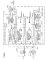
- FIG. 6 shows details of the receiving device of FIG. 4 .
- the receiving device includes the guard interval removing unit(s) (-CP) 41, the fast Fourier transform unit(s) (FFT-and-demapping unit(s)) 42, the QR decomposition unit 210, the signal transformation unit 212, the MLD unit 214, the likelihood output unit 215, a channel estimation unit 62, and a permutation control unit 64.
- the guard interval removing unit (-CP) 41 removes guard intervals from a received baseband signal.
- the fast Fourier transform unit (FFT-and-demapping unit) 42 fast-Fourier-transforms the received signal and thereby transforms the received signal in the time domain into a signal in the frequency domain.
- FFT-and-demapping unit 42 performs both fast Fourier transformation and demapping.
- an FFT unit and a demapping unit may be provided separately.
- the channel estimation unit 62 estimates radio channel conditions of respective subcarriers and obtains a channel matrix H for each of the subcarriers. Accordingly, channel matrices H of all subcarriers form a matrix of N RX ⁇ N DFT rows and N TX ⁇ N DFT columns. Matrix elements of the channel matrix H may be obtained, for example, based on reception conditions of a pilot signal.
- the signal transformation unit 212 multiplies a vector Y including multiple received signals as elements by a conjugate transposed matrix Q H of the unitary matrix Q to transform the received signals.
- the unitary-transformed received signals can be expressed by the product of the upper triangular matrix R and a transmission symbol sequence x.
- the MLD unit 214 narrows down symbol candidates of transmission signals by a maximum likelihood detection (MLD) method.
- the branch metrics are represented by square Euclidean distances between the received signals and the symbol candidates.
- the MLD unit 214 selects, as surviving candidates, a predetermined number (M) of symbol candidates in ascending order of cumulative branch metrics, and goes onto the next stage. In each of N TX ⁇ N DFT stages, the MLD unit 214 calculates branch metrics and selects surviving candidates.
- the likelihood output unit 215 calculates the likelihood of symbol candidates output from the surviving symbol candidate selecting unit of the last stage. For example, the likelihood is represented by a log likelihood ratio (LLR). An output from the likelihood output unit 215 indicates signal separation results and is sent to a demodulation unit that follows.
- LLR log likelihood ratio
- the permutation control unit 64 inputs a control signal to the QR decomposition unit 210.
- the control signal indicates a method of permuting columns of the matrix product F of the channel matrix H and the weight matrix W.
- Formula (9) described above holds regardless of the method of permutation. No single permutation method applies to all cases. Therefore, an appropriate permutation method is determined based on a certain criterion. As described later, the columns of the matrix product F may be permuted based on received power (at the receiving device) of the transmission symbols (first method) and/or based on subcarriers (second method).
- a first method (permutation according to transmitting antennas) of the second variation is described below.
- the columns of the matrix product F is permuted based on received power of transmission symbols at the receiving device.
- symbols estimated in first through (k-1)th stages and a k-th row of the upper triangular matrix R are used.
- the number of code-division-multiplexed transmission symbol sequences corresponds to the number of transmitting antennas.
- the components of a transmission symbol sequence transmitted from one transmitting antenna show the same received signal power.
- a transmitting antenna providing higher received power is identified, and symbols transmitted from the identified transmitting antenna are preferentially estimated prior to symbols from other transmitting antennas.
- Any appropriate method may be used to measure received power levels of symbols from respective transmitting antennas.
- matrix elements of a channel matrix may be used for this purpose. As described above, the channel matrix H i for the i-th subcarrier has dimensions of N RX rows and N TX columns.
- N RX indicates the total number of receiving antennas and N TX indicates the total number of transmitting antennas.
- a matrix element h i,pq of the channel matrix H i indicates one of channel conditions (transfer functions), which corresponds to the i-th subcarrier, between the p-th receiving antenna and the q-th transmitting antenna. Therefore, the sum of
- 2 of all receiving antennas (p 1-N RX ) can be used to estimate the received power of a symbol from the q-th transmitting antenna.
- the columns of the matrix product F' and the components of the transmission symbol sequence x are permuted.
- the components of the transmission symbol sequence x 1 are moved to lower positions in the column vector to give priority to symbols from the first transmitting antenna.
- the order in which the subcarrier components x 11 , x 12 , and x 13 in the transmission symbol sequence x 1 are estimated is not uniquely determined yet.
- the subcarrier components x 11 , x 12 , and x 13 may be estimated in ascending order of subcarrier numbers.
- the subcarrier components may also be permuted in any other order.
- the numbers of antennas and the number of subcarriers are just examples, and any other values may be used.
- a second method of the second variation (permutation according to subcarriers) is described below.
- a combination of symbols with high fading correlation tend to cause a serious error.
- High fading correlation between symbols indicates that the symbols are subject to a similar level of fading.
- Low fading correlation between symbols indicates that the symbols are subject to different levels of fading.
- the fading correlation is represented by a value greater than or equal to 0 and less than or equal to 1. The fading correlation increases as the value nears 1 and decreases as the value nears 0.
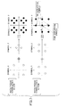
- FIG. 7 is a drawing used to describe that the level of difficulty in determining a combination of symbols varies depending on the degree of fading correlation.
- N TX and the number of receiving antennas N RX are both 2.
- a symbol 1 (x 1 ) is transmitted from a first transmitting antenna.
- a symbol 2 (x 2 ) is transmitted from a second transmitting antenna.
- the symbols transmitted from the transmitting antennas are data modulated by QPSK.
- each symbol is one of four signal points on a signal constellation. In other words, there are four candidates for each of the symbols 1 and 2. Therefore, the number of combinations is 16.
- the symbols 1 and 2 are received at the receiving device as a combined signal (r i1 , r i2 ).
- permutation is performed such that symbols subject to a similar level of fading are not estimated consecutively.
- the order of symbol detection is determined such that after a first symbol is estimated, a second symbol subject to a different level of fading from that of the first symbol is estimated. More specifically, the order of symbol detection is controlled such that a transmission symbol from a first transmitting antenna is estimated and then a transmission symbol from a second transmitting antenna is estimated.
- the degree of fading correlation may be determined by any appropriate method.
- the degree of fading correlation may be determined based on the similarity of amplitudes and phases of matrix elements h i,pq of the channel matrix. Taking the i-th subcarrier as an example, when pilot signals with a size 1 are transmitted, respectively, from an a-th transmitting antenna and a b-th transmitting antenna and received by a p-th receiving antenna, the fading correlation between the two received signals may be evaluated by h i,pa *h i,pb (where * indicates complex conjugate). Needless to say, any other appropriate method may be used to determine the degree of fading correlation.
- symbols from transmitting antennas may be estimated subcarrier by subcarrier.
- signals transmitted from the same antenna are subject to a similar level of fading and therefore have high fading correlation.
- signals transmitted from different antennas are subject to different levels of fading and therefore have low fading correlation.
- N TX transmission symbols (subcarrier components) transmitted using the i-th subcarrier are estimated, next N TX transmission symbols transmitted using the i+1-th subcarrier are estimated. Similar steps are repeated, and symbols with low fading correlation are estimated successively.
- subcarriers are selected sequentially in ascending order of subcarrier numbers and for each selected subcarrier, symbols transmitted from all transmitting antennas are estimated.
- subcarrier components are estimated in ascending order of subcarrier numbers.
- the order of estimating subcarrier components is not limited to the ascending order of subcarrier numbers.
- the numbers of antennas and the number of subcarriers are just examples, and any other values may be used.
Landscapes
- Engineering & Computer Science (AREA)
- Computer Networks & Wireless Communication (AREA)
- Signal Processing (AREA)
- Power Engineering (AREA)
- Radio Transmission System (AREA)
- Mobile Radio Communication Systems (AREA)
Applications Claiming Priority (3)
| Application Number | Priority Date | Filing Date | Title |
|---|---|---|---|
| JP2008024355 | 2008-02-04 | ||
| JP2008315035A JP5122428B2 (ja) | 2008-02-04 | 2008-12-10 | 移動通信システム、受信装置及び方法 |
| PCT/JP2009/051626 WO2009099013A1 (ja) | 2008-02-04 | 2009-01-30 | 移動通信システム、受信装置及び方法 |
Publications (2)
| Publication Number | Publication Date |
|---|---|
| EP2242197A1 true EP2242197A1 (de) | 2010-10-20 |
| EP2242197A4 EP2242197A4 (de) | 2016-05-11 |
Family
ID=40952088
Family Applications (1)
| Application Number | Title | Priority Date | Filing Date |
|---|---|---|---|
| EP09707309.2A Withdrawn EP2242197A4 (de) | 2008-02-04 | 2009-01-30 | Mobilkommunikationssystem, empfangsgerät und verfahren dafür |
Country Status (8)
| Country | Link |
|---|---|
| US (1) | US8320507B2 (de) |
| EP (1) | EP2242197A4 (de) |
| JP (1) | JP5122428B2 (de) |
| KR (1) | KR20100122478A (de) |
| CN (1) | CN101981847B (de) |
| BR (1) | BRPI0906353A2 (de) |
| RU (1) | RU2481712C2 (de) |
| WO (1) | WO2009099013A1 (de) |
Cited By (2)
| Publication number | Priority date | Publication date | Assignee | Title |
|---|---|---|---|---|
| WO2019127932A1 (zh) * | 2017-12-29 | 2019-07-04 | 深圳超级数据链技术有限公司 | 一种qr分解检测方法和装置 |
| EP3557923A4 (de) * | 2016-12-19 | 2020-07-22 | Ntt Docomo, Inc. | Benutzerendgerät |
Families Citing this family (24)
| Publication number | Priority date | Publication date | Assignee | Title |
|---|---|---|---|---|
| US8199841B1 (en) | 2007-04-26 | 2012-06-12 | Marvell International Ltd. | Channel tracking in a wireless multiple-input multiple-output (MIMO) communication system |
| JP5074148B2 (ja) * | 2007-10-19 | 2012-11-14 | 株式会社日立国際電気 | 最尤復号化方法、最尤復号装置、及び受信機 |
| WO2009122842A1 (ja) * | 2008-04-04 | 2009-10-08 | 株式会社 エヌ・ティ・ティ・ドコモ | 移動通信システム、受信装置及び方法 |
| JP5576168B2 (ja) * | 2010-04-09 | 2014-08-20 | 株式会社Nttドコモ | 無線受信装置及び無線受信方法 |
| CN102255642B (zh) * | 2010-05-19 | 2014-01-01 | 华为技术有限公司 | 一种干扰消除方法及设备、系统 |
| US9070972B2 (en) * | 2011-06-30 | 2015-06-30 | Sony Corporation | Wideband beam forming device; wideband beam steering device and corresponding methods |
| US8693561B2 (en) | 2012-03-16 | 2014-04-08 | Posedge Inc. | Receive signal detection of multi-carrier signals |
| US9106470B2 (en) | 2012-12-03 | 2015-08-11 | Qualcomm Incorporated | Enhanced decoding and demapping method and apparatus for QAM data signals |
| KR20150127480A (ko) * | 2014-05-07 | 2015-11-17 | 한국전자통신연구원 | 부분 ml을 근거로 한 신호 검출 시스템 및 그 방법 |
| CN107004117B (zh) * | 2014-12-09 | 2020-01-21 | 华为技术有限公司 | 一种检测发送序列的方法、接收机和接收设备 |
| US10110346B1 (en) * | 2016-04-14 | 2018-10-23 | Mbit Wireless, Inc. | Method and apparatus for soft bit computation in MIMO decoders |
| US10020839B2 (en) | 2016-11-14 | 2018-07-10 | Rampart Communications, LLC | Reliable orthogonal spreading codes in wireless communications |
| CN110089084B (zh) * | 2016-12-19 | 2022-08-12 | 株式会社Ntt都科摩 | 终端 |
| CN106911374B (zh) * | 2017-01-16 | 2020-08-04 | 重庆邮电大学 | 一种低复杂度软输出空间调制检测方法 |
| US10873361B2 (en) | 2019-05-17 | 2020-12-22 | Rampart Communications, Inc. | Communication system and methods using multiple-in-multiple-out (MIMO) antennas within unitary braid divisional multiplexing (UBDM) |
| US11025470B2 (en) | 2019-07-01 | 2021-06-01 | Rampart Communications, Inc. | Communication system and method using orthogonal frequency division multiplexing (OFDM) with non-linear transformation |
| US10833749B1 (en) * | 2019-07-01 | 2020-11-10 | Rampart Communications, Inc. | Communication system and method using layered construction of arbitrary unitary matrices |
| US11050604B2 (en) | 2019-07-01 | 2021-06-29 | Rampart Communications, Inc. | Systems, methods and apparatuses for modulation-agnostic unitary braid division multiplexing signal transformation |
| US10917148B2 (en) | 2019-07-01 | 2021-02-09 | Rampart Communications, Inc. | Systems, methods and apparatus for secure and efficient wireless communication of signals using a generalized approach within unitary braid division multiplexing |
| US11641269B2 (en) | 2020-06-30 | 2023-05-02 | Rampart Communications, Inc. | Modulation-agnostic transformations using unitary braid divisional multiplexing (UBDM) |
| US10951442B2 (en) | 2019-07-31 | 2021-03-16 | Rampart Communications, Inc. | Communication system and method using unitary braid divisional multiplexing (UBDM) with physical layer security |
| US10735062B1 (en) | 2019-09-04 | 2020-08-04 | Rampart Communications, Inc. | Communication system and method for achieving high data rates using modified nearly-equiangular tight frame (NETF) matrices |
| US10965352B1 (en) | 2019-09-24 | 2021-03-30 | Rampart Communications, Inc. | Communication system and methods using very large multiple-in multiple-out (MIMO) antenna systems with extremely large class of fast unitary transformations |
| US11159220B2 (en) | 2020-02-11 | 2021-10-26 | Rampart Communications, Inc. | Single input single output (SISO) physical layer key exchange |
Family Cites Families (17)
| Publication number | Priority date | Publication date | Assignee | Title |
|---|---|---|---|---|
| US6785341B2 (en) * | 2001-05-11 | 2004-08-31 | Qualcomm Incorporated | Method and apparatus for processing data in a multiple-input multiple-output (MIMO) communication system utilizing channel state information |
| US7280625B2 (en) * | 2002-12-11 | 2007-10-09 | Qualcomm Incorporated | Derivation of eigenvectors for spatial processing in MIMO communication systems |
| US20080256426A1 (en) * | 2004-11-12 | 2008-10-16 | Nokia Siemens Networks Oy | Low Density Parity Check Codes For Mimo Systems |
| JP4308159B2 (ja) * | 2005-02-10 | 2009-08-05 | 日本電信電話株式会社 | 空間多重信号検出回路 |
| JP4290660B2 (ja) * | 2005-02-14 | 2009-07-08 | 日本電信電話株式会社 | 空間多重信号検出回路及び空間多重信号検出方法 |
| US7602855B2 (en) * | 2005-04-01 | 2009-10-13 | Interdigital Technology Corporation | Method and apparatus for singular value decomposition of a channel matrix |
| JP4666150B2 (ja) * | 2005-05-31 | 2011-04-06 | 日本電気株式会社 | Mimo受信装置、受信方法、および無線通信システム |
| US20060285531A1 (en) * | 2005-06-16 | 2006-12-21 | Howard Steven J | Efficient filter weight computation for a MIMO system |
| WO2007037716A1 (en) * | 2005-09-30 | 2007-04-05 | Intel Corporation | Communication system and technique using qr decomposition with a triangular systolic array |
| ES2437574T3 (es) * | 2006-04-27 | 2014-01-13 | Telecom Italia S.P.A. | Estimación de canal de dominio de frecuencia en un sistema de acceso múltiple por división de frecuencia con portadora única |
| JP4854378B2 (ja) * | 2006-05-01 | 2012-01-18 | ソフトバンクBb株式会社 | 無線伝送システムおよび無線伝送方法 |
| KR101382760B1 (ko) * | 2007-03-21 | 2014-04-08 | 엘지전자 주식회사 | 다중 안테나를 이용한 통신시스템에서 코드북을 이용한데이터 전송방법 |
| US8199841B1 (en) * | 2007-04-26 | 2012-06-12 | Marvell International Ltd. | Channel tracking in a wireless multiple-input multiple-output (MIMO) communication system |
| KR100965728B1 (ko) * | 2007-06-12 | 2010-06-24 | 삼성전자주식회사 | 최대 우도 방식을 사용한 신호 검출 장치 및 방법 |
| GB2453776B (en) * | 2007-10-18 | 2010-05-19 | Toshiba Res Europ Ltd | Wireless communications apparatus |
| KR100934007B1 (ko) * | 2007-12-18 | 2009-12-28 | 한국전자통신연구원 | 다중입력 다중출력 수신기에서 다차원 검출 장치 및방법과, 이를 이용한 수신 장치 |
| US8411781B2 (en) * | 2009-06-11 | 2013-04-02 | Mediatek Inc. | Method and system for operating a MIMO decoder |
-
2008
- 2008-12-10 JP JP2008315035A patent/JP5122428B2/ja not_active Expired - Fee Related
-
2009
- 2009-01-30 EP EP09707309.2A patent/EP2242197A4/de not_active Withdrawn
- 2009-01-30 BR BRPI0906353-6A patent/BRPI0906353A2/pt not_active IP Right Cessation
- 2009-01-30 KR KR1020107017038A patent/KR20100122478A/ko not_active Ceased
- 2009-01-30 US US12/864,888 patent/US8320507B2/en not_active Expired - Fee Related
- 2009-01-30 WO PCT/JP2009/051626 patent/WO2009099013A1/ja not_active Ceased
- 2009-01-30 CN CN2009801116820A patent/CN101981847B/zh not_active Expired - Fee Related
- 2009-01-30 RU RU2010135412/07A patent/RU2481712C2/ru not_active IP Right Cessation
Non-Patent Citations (1)
| Title |
|---|
| See references of WO2009099013A1 * |
Cited By (4)
| Publication number | Priority date | Publication date | Assignee | Title |
|---|---|---|---|---|
| EP3557923A4 (de) * | 2016-12-19 | 2020-07-22 | Ntt Docomo, Inc. | Benutzerendgerät |
| WO2019127932A1 (zh) * | 2017-12-29 | 2019-07-04 | 深圳超级数据链技术有限公司 | 一种qr分解检测方法和装置 |
| CN109995463A (zh) * | 2017-12-29 | 2019-07-09 | 深圳超级数据链技术有限公司 | 一种qr分解检测方法和装置 |
| US11283544B2 (en) | 2017-12-29 | 2022-03-22 | Shen Zhen Kuang-Chi Hezhong Technology Ltd. | QR decomposition-based detection method and apparatus |
Also Published As
| Publication number | Publication date |
|---|---|
| RU2010135412A (ru) | 2012-03-20 |
| US8320507B2 (en) | 2012-11-27 |
| CN101981847B (zh) | 2013-12-25 |
| CN101981847A (zh) | 2011-02-23 |
| WO2009099013A1 (ja) | 2009-08-13 |
| BRPI0906353A2 (pt) | 2015-07-07 |
| JP2009213124A (ja) | 2009-09-17 |
| KR20100122478A (ko) | 2010-11-22 |
| EP2242197A4 (de) | 2016-05-11 |
| RU2481712C2 (ru) | 2013-05-10 |
| US20100329393A1 (en) | 2010-12-30 |
| JP5122428B2 (ja) | 2013-01-16 |
Similar Documents
| Publication | Publication Date | Title |
|---|---|---|
| EP2242197A1 (de) | Mobilkommunikationssystem, empfangsgerät und verfahren dafür | |
| EP2267925B1 (de) | Mobilkommunikationssystem, empfangsgerät und verfahren dafür | |
| CN101005475A (zh) | 正交频分复用通信中时间和频率同步的方法及系统 | |
| JP2011151803A (ja) | 送信機及び受信機を含むネットワークにおいてシンボルを通信するための方法 | |
| EP2101459B1 (de) | Verfahren und Einrichtung für die Untersuchung ob ein vorgegebenes Signal in einem vorgegebenen Set von OFDM Resourcen-Elementen empfangen worden ist | |
| US20100208847A1 (en) | OFDM Receiver for Dispersive Environment | |
| CN102045285A (zh) | 信道估计方法、装置以及通信系统 | |
| CN107317612B (zh) | 发送装置、接收装置、发送方法、接收方法以及通信系统 | |
| CN102685060B (zh) | 一种正交频分复用系统中多用户mimo接收方法和装置 | |
| Bhoyar et al. | Leaky least mean square (LLMS) algorithm for channel estimation in BPSK-QPSK-PSK MIMO-OFDM system | |
| CN101018219A (zh) | 一种空频信号处理方法 | |
| JP2002330114A (ja) | Gmmseタイプの等化方法および装置ならびに受信機 | |
| Hassan et al. | Variable pilot channels estimation based on blocktype and comb-type pilot arrangement in OFDM system | |
| Maltsev et al. | Comparative analysis of spatial covariance matrix estimation methods in OFDM communication systems | |
| Kahlon et al. | Channel estimation techniques in MIMO-OFDM systems–review article | |
| US7324435B2 (en) | Methods and apparatus for receiving OFDM signals | |
| EP2541798A1 (de) | Robutes Strahlenbündelungsverfahren und Strahlenbündelungsvorrichtung | |
| Surendher et al. | An Evaluation of Channel Estimation Methods for MIMO-OFDM System | |
| Yang et al. | Massive MIMO performance with timing & frequency errors | |
| D'Amours et al. | Subspace decomposition for channel estimation in SC-FDE systems | |
| Manco-Vásquez et al. | Spread spectrum orthogonalization of superimposed training signals in OFDM systems | |
| Nahm et al. | Time-and frequency-domain hybrid detection scheme for OFDM-CDMA systems | |
| Kwok et al. | Precoded MIMO-SC-FDE and blind channel estimation | |
| Punnoose et al. | Blind channel estimation for MIMO uplink MC-CDMA systems with layered space frequency equalisation | |
| Punnoose et al. | Blind channel estimation for MIMO uplink single carrier CDMA block transmission systems |
Legal Events
| Date | Code | Title | Description |
|---|---|---|---|
| PUAI | Public reference made under article 153(3) epc to a published international application that has entered the european phase |
Free format text: ORIGINAL CODE: 0009012 |
|
| 17P | Request for examination filed |
Effective date: 20100805 |
|
| AK | Designated contracting states |
Kind code of ref document: A1 Designated state(s): AT BE BG CH CY CZ DE DK EE ES FI FR GB GR HR HU IE IS IT LI LT LU LV MC MK MT NL NO PL PT RO SE SI SK TR |
|
| AX | Request for extension of the european patent |
Extension state: AL BA RS |
|
| DAX | Request for extension of the european patent (deleted) | ||
| RA4 | Supplementary search report drawn up and despatched (corrected) |
Effective date: 20160407 |
|
| RIC1 | Information provided on ipc code assigned before grant |
Ipc: H04J 11/00 20060101ALI20160401BHEP Ipc: H04B 7/04 20060101ALI20160401BHEP Ipc: H04L 27/01 20060101ALI20160401BHEP Ipc: H04L 25/03 20060101ALI20160401BHEP Ipc: H04J 99/00 20090101AFI20160401BHEP |
|
| STAA | Information on the status of an ep patent application or granted ep patent |
Free format text: STATUS: THE APPLICATION IS DEEMED TO BE WITHDRAWN |
|
| 18D | Application deemed to be withdrawn |
Effective date: 20161108 |