EP2242062A2 - Method and system for irradiation and elution of a capsule - Google Patents
Method and system for irradiation and elution of a capsule Download PDFInfo
- Publication number
- EP2242062A2 EP2242062A2 EP10159636A EP10159636A EP2242062A2 EP 2242062 A2 EP2242062 A2 EP 2242062A2 EP 10159636 A EP10159636 A EP 10159636A EP 10159636 A EP10159636 A EP 10159636A EP 2242062 A2 EP2242062 A2 EP 2242062A2
- Authority
- EP
- European Patent Office
- Prior art keywords
- end portion
- capsule
- filter
- washer
- elution
- Prior art date
- Legal status (The legal status is an assumption and is not a legal conclusion. Google has not performed a legal analysis and makes no representation as to the accuracy of the status listed.)
- Granted
Links
Images



Classifications
-
- G—PHYSICS
- G21—NUCLEAR PHYSICS; NUCLEAR ENGINEERING
- G21G—CONVERSION OF CHEMICAL ELEMENTS; RADIOACTIVE SOURCES
- G21G1/00—Arrangements for converting chemical elements by electromagnetic radiation, corpuscular radiation or particle bombardment, e.g. producing radioactive isotopes
- G21G1/0005—Isotope delivery systems
-
- G—PHYSICS
- G21—NUCLEAR PHYSICS; NUCLEAR ENGINEERING
- G21G—CONVERSION OF CHEMICAL ELEMENTS; RADIOACTIVE SOURCES
- G21G1/00—Arrangements for converting chemical elements by electromagnetic radiation, corpuscular radiation or particle bombardment, e.g. producing radioactive isotopes
- G21G1/02—Arrangements for converting chemical elements by electromagnetic radiation, corpuscular radiation or particle bombardment, e.g. producing radioactive isotopes in nuclear reactors
-
- G—PHYSICS
- G21—NUCLEAR PHYSICS; NUCLEAR ENGINEERING
- G21G—CONVERSION OF CHEMICAL ELEMENTS; RADIOACTIVE SOURCES
- G21G4/00—Radioactive sources
- G21G4/02—Neutron sources
-
- G—PHYSICS
- G21—NUCLEAR PHYSICS; NUCLEAR ENGINEERING
- G21G—CONVERSION OF CHEMICAL ELEMENTS; RADIOACTIVE SOURCES
- G21G4/00—Radioactive sources
- G21G4/04—Radioactive sources other than neutron sources
-
- G—PHYSICS
- G21—NUCLEAR PHYSICS; NUCLEAR ENGINEERING
- G21G—CONVERSION OF CHEMICAL ELEMENTS; RADIOACTIVE SOURCES
- G21G1/00—Arrangements for converting chemical elements by electromagnetic radiation, corpuscular radiation or particle bombardment, e.g. producing radioactive isotopes
- G21G1/001—Recovery of specific isotopes from irradiated targets
- G21G2001/0042—Technetium
-
- Y—GENERAL TAGGING OF NEW TECHNOLOGICAL DEVELOPMENTS; GENERAL TAGGING OF CROSS-SECTIONAL TECHNOLOGIES SPANNING OVER SEVERAL SECTIONS OF THE IPC; TECHNICAL SUBJECTS COVERED BY FORMER USPC CROSS-REFERENCE ART COLLECTIONS [XRACs] AND DIGESTS
- Y02—TECHNOLOGIES OR APPLICATIONS FOR MITIGATION OR ADAPTATION AGAINST CLIMATE CHANGE
- Y02E—REDUCTION OF GREENHOUSE GAS [GHG] EMISSIONS, RELATED TO ENERGY GENERATION, TRANSMISSION OR DISTRIBUTION
- Y02E30/00—Energy generation of nuclear origin
- Y02E30/30—Nuclear fission reactors
Definitions
- the invention relates to a capsule and methods of fabricating and using the capsule.
- the capsule is designed to fit within a nuclear reactor's neutron flux so that a material within the capsule may be irradiated in the reactor's core.
- the capsule is further designed to be used straight from the neutron flux source and used as an elution column to remove ions from within the capsule that were generated by the irradiation decay process.
- Technetium-99m (m is metastable) is a radionuclide used in nuclear medical diagnostic imaging. Technetium-99m is injected into a patient which, when used with certain equipment, is used to image the patient's internal organs. However, technetium-99m has a halflife of only six (6) hours, therefore, readily available sources of technetium-99m are desired.
- a method for obtaining technetium-99m uses a minimum of a two-step process.
- titanium molybdate is placed in a capsule, which is then irradiated in a nuclear reactor.
- Molybdenum-98 within the titanium molybdate absorbs a neutron during the irradiation process and becomes molybdenum-99 (Mo-99).
- Mo-99 is unstable and decays with a 66-hour half-life to technetium-99m (m is metastable).
- the irradiated titanium molybdate is removed from the capsule and placed in a column for elution.
- saline is passed through the irradiated titanium molybdate to remove the technetium-99m ions from the irradiated titanium molybdate.
- an elution capsule may include a tube with a first end portion having a first inside diameter, a second end portion having a second inside diameter, and a middle portion between the first end portion and the second end portion having an inside diameter smaller than the inside diameters of the first and second end portions.
- the interface between the first end portion and the middle portion forms a first shoulder and the interface between the second end portion and the middle portion forms a second shoulder.
- the elution capsule may also include a first washer inside the first end portion contacting the first shoulder, a first filter inside the first end portion contacting the first washer, and a second filter inside the first end portion such that the first filter is between the first washer and the second filter.
- the first end may be sealed by a first end cap.
- the elution capsule may also include a second washer inside the second end portion contacting the second shoulder, a third filter inside the second end portion contacting the second washer, and a fourth filter inside the second end portion such that the third filter is between the second washer and the fourth filter.
- the second end portion may be sealed by a second end cap.
- the elution capsule may include a tube with a first end portion having a first inside diameter, a second end portion having a second inside diameter, and a middle portion having an inside diameter smaller than the inside diameters of the first and second end portions.
- the middle portion is between the first end portion and the second end portion and is configured to hold the material.
- the interface between the first end portion and the middle portion forms a first shoulder and the interface between the second end portion and the middle portion forms a second shoulder.
- a first washer may be inside the first end portion and may contact the first shoulder.
- a first filter may be inside the first end portion and may contact the first washer.
- a second filter may be inside the first end portion and may be positioned such that the first filter is between the first washer and the second filter.
- a first end cap may be provided in the first end portion to seal-off the first end portion.
- a second washer may be inside the second end portion and may contact the second shoulder.
- a third filter may be inside the second end portion and may contact the second washer.
- a fourth filter inside the second end portion may be provided such that the third filter is between the second washer and the fourth filter.
- a second end cap may be provided in the second portion to seal-off the second end portion.
- the method may include placing the sealed elution capsule, with the material in the middle portion of the elution capsule in a neutron flux source and irradiating the capsule and its contents in the reactor's core.
- At least one example embodiment related to a method of eluting a material enclosed in a sealed elution capsule includes placing the sealed elution capsule enclosing the material into a nuclear reactor, irradiating the sealed elution capsule and material in a reactor, removing the sealed elution capsule and irradiated material from the reactor, and performing an elution step by puncturing a first end portion of the elution capsule with a needle to supply a solution to the elution capsule and puncturing a second end portion with a needle to provide a vacuum to draw the solution through the irradiated material to collect the eluant.
- first, second, etc. may be used herein to describe various elements, components, regions, layers, and/or sections, these elements, components, regions, layers, and/or sections should not be limited by these terms. These terms are only used to distinguish one element, component, region, layer, and/or section from another element, component, region, layer, and/or section. Thus, a first element, component, region, layer, or section discussed below could be termed a second element, component, region, layer, or section without departing from the teachings of example embodiments.
- spatially relative terms such as “beneath”, “below”, “lower”, “above”, “upper”, and the like, may be used herein for ease of description to describe one element or feature's relationship to another element(s) or feature(s) as illustrated in the figures. It will be understood that the spatially relative terms are intended to encompass different orientations of the device in use or operation in addition to the orientation depicted in the figures. For example, if the device in the figures is turned over, elements described as “below” or “beneath” other elements or features would then be oriented “above” the other elements or features. Thus, the exemplary term “below” can encompass both an orientation of above and below. The device may be otherwise oriented (rotated 90 degrees or at other orientations) and the spatially relative descriptors used herein interpreted accordingly.
- Embodiments described herein will refer to plan views and/or cross-sectional views by way of ideal schematic views. Accordingly, the views may be modified depending on manufacturing technologies and/or tolerances. Therefore, example embodiments are not limited to those shown in the views, but include modifications in configuration formed on the basis of manufacturing processes. Therefore, regions exemplified in figures have schematic properties and shapes of regions shown in figures exemplify specific shapes or regions of elements, and do not limit example embodiments.
- FIGS. 1-3 represent an example embodiment of the present invention.
- the example embodiment as shown in FIGS. 1-3 , includes a hollow cylindrically shaped multidiameter tube 10.
- the tube 10 is hollow such that a cross-section of the multidiameter tube has an annular shape.
- the tube 10 has a constant outer diameter D1, however, the inner diameter of the tube 10 varies along the length of the tube 10.
- the tube as shown in FIG. 1 , includes three portions: a first end portion 12 located at one end of the multidiameter tube 10, a second end portion 14 located at another end of the multidiameter tube 10, and a middle portion 16 between the first end portion 12 and the second end portion 14.
- the inner diameter D4 of the middle portion 16 may be smaller than the inner diameters D2 and D3 of the end portions 12 and 14.
- the inner diameter of the first end portion D2 and the inner diameter of the second end portion D3 may be equal.
- the first end portion 12 and the second end portion 14 may have lengths P1 and P2, respectively. As shown in FIG. 3 , the lengths P1 and P2 may be equal. The interface between the first end portion 12 and the middle portion 16 forms a first shoulder 100 and the interface between the second end portion 14 and the middle portion 16 forms a second shoulder 110. Because the lengths P1 and P2 may be equal and because the diameters D1 and D2 may likewise be equal, the multidiameter tube 10 illustrated in FIGS. 1-3 may have a symmetric configuration.
- the example capsule 1 for holding, irradiating and eluting a material in accordance with FIGS. 1-3 also includes first and second washers 20 and 60 positioned inside the first end portion 12 and the second end portion 14, respectively.
- the washers 20 and 60 as shown in FIGS. 1 , 2 , 4 and 5 , are short hollow cylinders with annular cross-sections.
- the washer 20 has an outside diameter D6 larger than the inside diameter D4 of the middle portion 16 and smaller than the inside diameter D2 of the first end portion 12.
- the washer 20 has an inside diameter D5 that may be smaller, equal to, or larger than the diameter of the inside diameter D4 of the middle portion 16.
- the washer 60 has an outside diameter D8 larger than the inside diameter D4 of the middle portion 16 and smaller than the inside diameter D3 of the second end portion 14.
- the washer 60 has an inside diameter D7 that may be smaller, equal to, or larger than the diameter of the inside diameter D4 of the middle portion 16.
- the washer 20 is placed inside the first end portion 12 and against the shoulder 100.
- the washer 60 is placed in the second end portion 14 and against the shoulder 110.
- the example capsule 1 for holding, irradiating, and eluting a material may also include first and second filters 30 and 40 in the first end portion 12 and third and fourth filters 70 and 80 in the second end portion 14 of the multidiameter tube 10.
- the first filter 30 may be placed in the first end portion such that the washer 20 is between the first filter 30 and the shoulder 100 and the second filter 40 may be placed in the first end portion 12 such that the first filter 30 is between the second filter 40 and the washer 20.
- the third filter 70 may be placed in the second end portion 14 such that the washer 60 is between the third filter 70 and the shoulder 110 and the fourth filter 80 may be placed in the second end portion 14 such that the third filter 70 is between the fourth filter 80 and the washer 60.
- the first through fourth filters may be made of various materials.
- the first filter 30 and the third filter 70 may be made from glass wool.
- the glass wool may be made from a borosilicate or quartz glass.
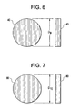
- the second filter 40 and the fourth filter 80 may be circular glass frits as shown in FIGS. 1 , 2 , and 6-7 which resemble short cylinders or disks.
- the glass frits may be made from various materials such as borosilicate glass, quartz glass, polyethylene, resin, or some other material that will structurally support a material within the elution tube and act as a filter to prevent material from traversing down a flow path through the elution tube.
- the circular glass frit 40 has an outer diameter D9 smaller than the inner diameter D2 of the first end portion 12 but greater than the inner diameter D5 of the washer 20.
- the circular glass frit 80 has an outer diameter D10 smaller than the inner diameter D3 of the second end portion 14 but larger than the inner diameter D7 of the washer 60.
- the example capsule 1 for holding, irradiating, and eluting a material may also include end caps 50 and 90 configured to seal the first end portion 12 and the second end portion 14 of the multidiameter tube 10, respectively.
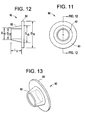
- the end caps 50 and 90 may include tapered hollow cylindrical body parts 52 and 92 with covers 53 and 93 as shown in FIGS. 1 , 2 and 8-13 , allowing the end caps 50 and 90 to be press fit into the first and second end portions 12 and 14 of the multidiameter tube. Because the ends of the multidiameter tube 1 are sealed by press fitting the end caps 50 and 90 into the first and second end portions 12 and 14, the end caps 50 and 90 should be made from a soft material which will accommodate yielding during the press fit process.
- the end caps may be made of aluminum.
- the hollow cylindrical body part 52 may be tapered so that the outer diameter D12 of a portion of the hollow cylindrical body part 52 facing the center of the multidiameter tube 10 is smaller than an outer diameter D14 of the hollow cylindrical body part 52 attached to the cover 53.
- the diameter D12 must be smaller than the inner diameter D2 of the first end portion 12 of the multidiameter tube 10 so that the end of the hollow body part 52 facing the center of the multidiameter tube 10 may enter the first end portion 12.
- the outer diameter D14 of the cylindrical body part 52 attached to the cover 53 should be slightly larger than the inner diameter D2 of the first end portion 12 of the multidiameter tube 10 so that when the end cap 50 is press fit into the first end portion 12 of the multidiameter tube 10 the first end portion is sealed.
- the inner diameter D11 of the hollow body part 52 should be smaller than the diameter D9 of the frit 40 to prevent the frit 40 from passing into the hollow body part 52.
- the length L1 of the hollow body part 52 should be long enough to accommodate a needle which may be passed through the cover 53 during an elution process.
- the length L1 of the hollow body part 52 therefore, should be at least as long as the needle used to introduce or remove a liquid into or from the example capsule 1 for holding, irradiating, and eluting a material. Because the length L1 of the hollow body part 52 is at least as long as the aforementioned needle, the hollow body part protects the first and second filter from being damaged by the needle as the needle is introduced into the capsule.
- the cover 53 of the end cap 50 has a diameter D15 larger than the inner diameter D2 of the first end portion 12 of the multidiameter tube to prevent the end cap 50 from completely passing into the first end portion 12. Because the cover 53 acts as a stop, the first and second filters 30 and 40 may be protected from being crushed by the hollow body 52 of the end cap 50 during the press fit process. Additionally, the cover 53 of the end cap 50 should be thin enough to allow puncture by a needle used in an elution process.
- the hollow cylindrical body part 92 may be tapered so that the outer diameter D16 of a portion of the hollow cylindrical body part 92 facing the center of the multidiameter tube 10 is smaller than an outer diameter D18 of the hollow cylindrical body part 92 attached to the cover 93.
- the diameter D16 must be smaller than the inner diameter D3 of the second end portion 14 of the multidiameter tube 10 so that the end of the hollow body part 92 facing the center of the multidiameter tube 10 may enter the second end portion 14.
- the outer diameter D18 of the cylindrical body part 92 attached to the cover 93 should be slightly larger than the inner diameter D3 of the second end portion 14 of the multidiameter tube 10 so that when the end cap 90 is press fit into the second end portion 14 of the multidiameter tube 10 the second end portion 14 forms a mechanical seal.
- the inner diameter D17 of the hollow body part 92 should be smaller than the diameter D10 of the frit 80 to prevent the frit 80 from passing into the hollow body part 92.
- the length L2 of the hollow body part 92 should be long enough to accommodate a needle which may be passed through the cover 93 during an elution process.
- the length L2 of the hollow body part 92 therefore, should be at least as long as the needle used to introduce or remove a liquid into or from the example capsule for holding, irradiating, and eluting a material. Because the length L2 of the hollow body part 92 is at least as long as the aforementioned needle, the hollow body part 92 protects the third and fourth filters 70 and 80 from being damaged by the needle as the needle is introduced into the capsule.
- the cover 93 of the end cap 90 has a diameter D19 larger than the inner diameter D3 of the second end portion 14 of the multidiameter tube 10 to prevent the end cap 90 from completely passing into the second end portion 14. Because the cover 93 acts as a stop, the third and fourth filters 70 and 80 may be protected from being crushed by the hollow body 92 of the end cap 90 during the press fit process. Additionally, the cover 93 of the end cap 90 should be thin enough to allow puncture by a needle used in an elution process.
- An adhesive may be applied to the outer surfaces of the hollow body parts 52 and 92 before the end caps 50 and 90 are press fit into the first and second end portions 12 and 14.
- the adhesive may provide additionally sealing to prevent materials in the capsule from escaping.
- the example capsule 1 for holding, irradiating, and eluting a material may also include a first and second seals 200 and 300 for covering the end caps 50 and 90 after the end caps 50 and 90 have been press fit into the first and second end portions 12 and 14, respectively.
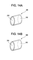
- Examples of the seals 200 and 300 are illustrated in FIG. 14 .
- the first and second seals include a hollow cylindrical body parts 210 and 310 and are closed at one end by end parts 220 and 320.
- the seals may be made from a flexible material, for example, a non-hardening rubber, so that the seals 200 and 300 can be snug fit over the first and second end portions 12 and 14 to create a second seal.
- the end parts 220 and 320 of the seals 200 and 300 must be thin enough to allow puncture by a needle used in an elution process. Additionally, the seals 200 and 300 may be epoxied onto the ends of the multidiameter tube 10 by applying epoxy to the inner surfaces of the cylindrical body parts 210 and 310 before the seals 200 and 300 are fitted over the first and second end portions of 12 and 14. The epoxy applied to the inner surfaces of the cylindrical body parts 210 and 310 may provide an extra seal to prevent materials within the capsule 1 from escaping.
- the multidiameter tube 10, the end caps 50 and 90, and the washers 20 and 60 should be made from materials that have a low nuclear cross section to avoid absorbing neutrons.
- materials include zirconium, quartz, aluminum or alloys including zirconium, quartz, glass and aluminum.
- the multidiameter tube 10, end caps 50 and 90, and the washers 20 and 60 may be made from zircaloy-2 or alternatively from aluminum 6061, high purity aluminum, and 4N and 5N aluminum.
- the multidiameter tube 10 may be fabricated by implementing a series of boring operations on a solid cylinder, for example, a solid cylinder of zirconium.
- the cylinder may have an outer diameter D1 and a length.
- the length of the cylinder may be determined based on the size of the nuclear reactor in which the cylinder will be irradiated and/or the size of a generator used in an elution process.
- a center of the cylinder may be bored out to a diameter of D4 transforming the solid cylinder into a hollow cylindrical tube.
- the hollow cylindrical tube may have a constant annular cross section with an inner diameter D4 and an outer diameter D1.
- One end of the hollow tube may have the diameter increased by a second boring operation to form a first end portion 12 having a length of P1 and an inner diameter of D2.
- a second end of the hollow tube may likewise have the diameter increased by a third boring operation to form a second end portion 14 having a length P2 and an inner diameter D3.
- the length P1 should be deep enough to accommodate the above described filters 30 and 40, the washer 20, and the hollow part 52 of the end cap 50.
- the length P2 should be deep enough to accommodate the above described filters 70 and 80, the washer 60, and the hollow part 92 of the end cap 90.
- the second and third boring operations transform the hollow cylindrical tube into a hollow multidiameter cylindrical tube 10 (see FIG. 3 ).
- the first end portion 12 has an annular cross section with an inner diameter D2 and an outer diameter D1 and the second end portion 14 has an annular cross section with an inner diameter D3 and an outer diameter D1.
- the portion of the tube between the first end portion 12 and the second end portion 14 constitutes a middle portion 16 with an annular cross section having an inner diameter D4 and an outer diameter D1.
- the depths P1 and P2 of the first end portion and the second end portion 12 and 14 of the multidiameter tube 10 by the second and third boring operations may be the same.
- the inner diameters D2 and D3 of the first and second end portions 12 and 14 may be the same. Accordingly, the multidiameter tube 10 may be fabricated to produce a symmetrical structure.
- the washers 20 and 60 may be fabricated by processes similar to those used in making the multidiameter tube 10. Because the washers 20 and 60 may be made by the same process, the process for making washer 60 is omitted for the sake of brevity.
- washers may be fabricated from a cylinder of zirconium having an outer diameter of D6 may be provided.
- the diameter D6 should be smaller than the diameter D2 associated with the first end portion 12 of the multidiameter tube 10.
- the cylinder may have a length that should be at least as long as a desired thickness for the washer.
- the cylinder may have the middle bored out to create a hollow tube.
- the tube has an annular cross section with an inner diameter D5 and an outer diameter D6 (see FIG. 4 ). An end portion of the tube may be cut along a cut line to form the washer 20 with a desired thickness.
- the end caps 50 and 90 may be fabricated by processes similar to those used in making the multidiameter tube 10. Because the end caps 50 and 90 may be made by the same process, the process for making the end cap 90 is omitted for the sake of brevity.
- end caps may be fabricated by a cylinder of zirconium having an outer diameter D14 may be provided.
- the diameter D14 should be larger than the diameter D2 of the first end portion 12 of the multidiameter tube 10 (see Figure 3 ).
- the cylinder is slightly longer than a length of a needle used to introduce or remove saline solution into or from the capsule 1 during the elution process.
- the cylinder may be placed in a die which fixes a portion of the cylinder.
- a first force may be applied to one end of the cylinder to deform the end of the cylinder to create a cover 53.
- the cover has a diameter D15 larger than the diameter D14 of the cylindrical body 52.
- a portion of the cylinder below the cover 53 may be bored out to create a hollow body portion.
- the hollow body portion resembles a circular tube having an annular cross section with an inner diameter D11 and an outer diameter D14.
- a second force may be applied laterally to the hollow body portion to deform the hollow body portion into a tapered shape. Application of the second force transforms the hollow body portion into a tapered hollow body 52.
- the end of the tapered hollow body 52 away from the cover 53 has an annular cross section having an inner diameter D11 and an outer diameter D12.
- the outer diameter D12 should be formed to be smaller than the inner diameter D2 of the first end portion 12 in order to allow the end cap 50 to enter into the first end portion 12.
- the washers 20 and 60, and the end caps 50 and 90 the capsule 1 may be assembled as shown in FIG. 2 .
- the washer 20 may be placed into the first end portion 12 so that the washer 20 bears up against the first shoulder 100.
- a first filter 30, for example, glass wool made from borosilicate glass, may be placed in the first end portion 12 so that washer 20 is between the first filter 30 and the shoulder 100.
- a second filter 40, for example, a glass frit made of borosilicate glass, may be provided in the first end portion 12 so that first filter 30 is between the second filter 40 and the washer 20.
- the end cap 50 may be inserted and press fit into the first end portion 12 thus sealing the first end portion 12.
- An epoxy may be provided on the outer surfaces of the hollow body part 52 of the end cap 50 before the press fitting operation to provide an extra added sealing means.
- the washer 60 may be placed into the second end portion 14 so that the washer 60 bears up against the second shoulder 110.
- a third filter 70 for example, glass wool made from borosilicate glass, may be placed in the second end portion 14 so that washer 60 is between the third filter 70 and the shoulder 110.
- a fourth filter 80 for example, a glass frit made of borosilicate glass, may be provided in the second end portion 14 so that third filter 70 is between the fourth filter 80 and the washer 60.
- the end cap 90 may be inserted and press fit into the second end portion 14 thus sealing the second end portion 14.
- An epoxy may be provided on the outer surfaces of the hollow body part 92 of end cap 90 before the press fitting operation to provide an extra added sealing means.
- extra seals 200 and 300 may be provided and placed on the ends of the capsule 1 after the first and second end portions 12 and 14 are sealed.
- the seals 200 and 300 may be provided for an extra seal.
- These seals may be made from a flexible material such as rubber and may be fabricated to provide a snug fit over the end portions of 12 and 14, of the capsule 1.
- the seals may include hollow body parts 210 and 310 and cover parts 220 and 320.
- the cover parts 220 and 320 should be sufficiently thin to allow for puncture by a needle in an elution process.
- epoxy may be applied to the inside surfaces of the hollow body parts 210 and 310 before the seals 200 and 300 are placed on the end portions 12 and 14 to provide for extra means for sealing the end portions of 12 and 14, of capsule 1.
- the example capsule 1 includes a multidiameter tube 10 with a first end portion 12, a second end portion 14, and a middle portion 16 between the end portion 12 and 14.
- the middle portion 16 holds a material for an irradiation process.
- the middle portion 16 may hold titanium molybdate, zirconium molybdate, titanium tungstenate, zirconyl tungstenate, or other ion exchange resin/gel matrix for elution.
- the material may be added to the middle portion 16 after the first end portion 12 has been assembled and sealed by the end cap 50 as described above. After the material is added to the middle portion 16, the second end portion 14 may be assembled and sealed as described above.
- the sealed capsule 1 (without the seals 200 and 300) including the material to be irradiated may be irradiated in a nuclear reactor. After the irradiation step, the capsule may be removed from the reactor and the seals 200 and 300 may be fixed to the capsule as described above. Referring to FIGS. 15 and 16 a method of eluting the ions generated by the irradiation step and subsequent radioactive decay is described.
- the capsule 1 includes an irradiated substance 6000.
- the elution process comprises two steps.
- the first step includes puncturing one end of the capsule 1 with a needle 7100 attached to a device 7000 for supplying a liquid, for example, distilled water, deionized water, saline, oxidizers, acids, bases, or any other water based solution, to the example capsule 1.
- a liquid for example, distilled water, deionized water, saline, oxidizers, acids, bases, or any other water based solution
- the seal 200 and the end cap 50 may be punctured by the needle 7100.
- the first and second filters 30 and 40 of capsule 1 are not damaged by the needle.
- a needle 8100 attached to a vacuum system 8000 punctures the end cap 90 and the seal 300.
- a vacuum system 8000 e.g. a vacuum bottle
- the needle 8100 is shorter than the length of the hollow body 92 of the end cap 90, the third and fourth filters 70 and 80 of capsule 1, are not damaged by the needle 8100.
- the vacuum from the vacuum system 8000 draws the fluid from the device 7000, through the irradiated material 6000, and into the vacuum system 8000. Accordingly, ions generated during the irradiation decay process may be collected in the vacuum system 8000.
Landscapes
- Physics & Mathematics (AREA)
- Engineering & Computer Science (AREA)
- Chemical & Material Sciences (AREA)
- Chemical Kinetics & Catalysis (AREA)
- General Chemical & Material Sciences (AREA)
- General Engineering & Computer Science (AREA)
- High Energy & Nuclear Physics (AREA)
- Plasma & Fusion (AREA)
- Sampling And Sample Adjustment (AREA)
- Nuclear Medicine (AREA)
- Radiation-Therapy Devices (AREA)
- Medical Preparation Storing Or Oral Administration Devices (AREA)
Abstract
Description
- The invention relates to a capsule and methods of fabricating and using the capsule. The capsule is designed to fit within a nuclear reactor's neutron flux so that a material within the capsule may be irradiated in the reactor's core. The capsule is further designed to be used straight from the neutron flux source and used as an elution column to remove ions from within the capsule that were generated by the irradiation decay process.
- Technetium-99m (m is metastable) is a radionuclide used in nuclear medical diagnostic imaging. Technetium-99m is injected into a patient which, when used with certain equipment, is used to image the patient's internal organs. However, technetium-99m has a halflife of only six (6) hours, therefore, readily available sources of technetium-99m are desired.
- A method for obtaining technetium-99m uses a minimum of a two-step process. First, titanium molybdate is placed in a capsule, which is then irradiated in a nuclear reactor. Molybdenum-98 within the titanium molybdate absorbs a neutron during the irradiation process and becomes molybdenum-99 (Mo-99). Mo-99 is unstable and decays with a 66-hour half-life to technetium-99m (m is metastable). After the irradiation step, the irradiated titanium molybdate is removed from the capsule and placed in a column for elution. Subsequently, saline is passed through the irradiated titanium molybdate to remove the technetium-99m ions from the irradiated titanium molybdate.
- At least one example embodiment relates to an elution capsule. In accordance with the example embodiment, an elution capsule may include a tube with a first end portion having a first inside diameter, a second end portion having a second inside diameter, and a middle portion between the first end portion and the second end portion having an inside diameter smaller than the inside diameters of the first and second end portions. The interface between the first end portion and the middle portion forms a first shoulder and the interface between the second end portion and the middle portion forms a second shoulder. The elution capsule may also include a first washer inside the first end portion contacting the first shoulder, a first filter inside the first end portion contacting the first washer, and a second filter inside the first end portion such that the first filter is between the first washer and the second filter. The first end may be sealed by a first end cap. The elution capsule may also include a second washer inside the second end portion contacting the second shoulder, a third filter inside the second end portion contacting the second washer, and a fourth filter inside the second end portion such that the third filter is between the second washer and the fourth filter. The second end portion may be sealed by a second end cap.
- In accordance with at least one example embodiment, a method of irradiating a material within an elution capsule is disclosed. In accordance with the example embodiment, the elution capsule may include a tube with a first end portion having a first inside diameter, a second end portion having a second inside diameter, and a middle portion having an inside diameter smaller than the inside diameters of the first and second end portions. The middle portion is between the first end portion and the second end portion and is configured to hold the material. The interface between the first end portion and the middle portion forms a first shoulder and the interface between the second end portion and the middle portion forms a second shoulder. A first washer may be inside the first end portion and may contact the first shoulder. A first filter may be inside the first end portion and may contact the first washer. A second filter may be inside the first end portion and may be positioned such that the first filter is between the first washer and the second filter. A first end cap may be provided in the first end portion to seal-off the first end portion. A second washer may be inside the second end portion and may contact the second shoulder. A third filter may be inside the second end portion and may contact the second washer. A fourth filter inside the second end portion may be provided such that the third filter is between the second washer and the fourth filter. A second end cap may be provided in the second portion to seal-off the second end portion. The method, according to the example embodiment, may include placing the sealed elution capsule, with the material in the middle portion of the elution capsule in a neutron flux source and irradiating the capsule and its contents in the reactor's core.
- At least one example embodiment related to a method of eluting a material enclosed in a sealed elution capsule is provided. The method includes placing the sealed elution capsule enclosing the material into a nuclear reactor, irradiating the sealed elution capsule and material in a reactor, removing the sealed elution capsule and irradiated material from the reactor, and performing an elution step by puncturing a first end portion of the elution capsule with a needle to supply a solution to the elution capsule and puncturing a second end portion with a needle to provide a vacuum to draw the solution through the irradiated material to collect the eluant.
- Example embodiments of the present invention will be more clearly understood from the following detailed description taken in conjunction with the accompanying drawings.
-
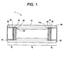
FIG.1 is a section view of an irradiation/elution capsule in accordance with an example embodiment of the present invention; -
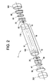
FIG. 2 is an exploded view of an irradiation/elution capsule in accordance with an example embodiment of the present invention; -
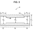
FIG. 3 is a section view of a multidiameter tube used in an irradiation /elution capsule in accordance with an example embodiment of the invention; -
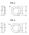
FIGS. 4 and 5 are plan views of washers used in an example irradiation/ elution capsule in accordance with an example embodiment of the invention; -
FIGS. 6 and 7 are plan views of filters used in an example irradiation elution capsule in accordance with an example embodiment of the invention; -
FIGS. 8-13 are views of end caps used in an irradiation/elution capsule in accordance with an example embodiment of the invention; -
FIG. 14 are views of a seals for sealing the ends of an example irradiation/elution capsule in accordance with an example embodiment of the invention -
FIGS. 15-16 illustrate steps for using an irradiation/elution capsule in accordance with an example embodiment of the invention. - Example embodiments of the invention will now be described more fully with reference to the accompanying drawings, in which example embodiments are shown. The invention may, however, be embodied in different forms and should not be construed as limited to the embodiments set forth herein. Rather, these embodiments are provided so that this disclosure will be thorough and complete, and will fully convey the scope of the invention to those skilled in the art. In the drawings, the sizes of components may be exaggerated for clarity.
- It will be understood that when an element or layer is referred to as being "on", "connected to", or "coupled to" another element or layer, it can be directly on, connected to, or coupled to the other element or layer or intervening elements or layers that may be present. In contrast, when an element is referred to as being "directly on", "directly connected to", or "directly coupled to" another element or layer, there are no intervening elements or layers present. As used herein, the term "and/or" includes any and all combinations of one or more of the associated listed items.
- It will be understood that, although the terms first, second, etc. may be used herein to describe various elements, components, regions, layers, and/or sections, these elements, components, regions, layers, and/or sections should not be limited by these terms. These terms are only used to distinguish one element, component, region, layer, and/or section from another element, component, region, layer, and/or section. Thus, a first element, component, region, layer, or section discussed below could be termed a second element, component, region, layer, or section without departing from the teachings of example embodiments.
- Spatially relative terms, such as "beneath", "below", "lower", "above", "upper", and the like, may be used herein for ease of description to describe one element or feature's relationship to another element(s) or feature(s) as illustrated in the figures. It will be understood that the spatially relative terms are intended to encompass different orientations of the device in use or operation in addition to the orientation depicted in the figures. For example, if the device in the figures is turned over, elements described as "below" or "beneath" other elements or features would then be oriented "above" the other elements or features. Thus, the exemplary term "below" can encompass both an orientation of above and below. The device may be otherwise oriented (rotated 90 degrees or at other orientations) and the spatially relative descriptors used herein interpreted accordingly.
- Embodiments described herein will refer to plan views and/or cross-sectional views by way of ideal schematic views. Accordingly, the views may be modified depending on manufacturing technologies and/or tolerances. Therefore, example embodiments are not limited to those shown in the views, but include modifications in configuration formed on the basis of manufacturing processes. Therefore, regions exemplified in figures have schematic properties and shapes of regions shown in figures exemplify specific shapes or regions of elements, and do not limit example embodiments.
-
FIGS. 1-3 represent an example embodiment of the present invention. The example embodiment, as shown inFIGS. 1-3 , includes a hollow cylindrically shapedmultidiameter tube 10. Thetube 10 is hollow such that a cross-section of the multidiameter tube has an annular shape. Thetube 10 has a constant outer diameter D1, however, the inner diameter of thetube 10 varies along the length of thetube 10. For example, the tube, as shown inFIG. 1 , includes three portions: afirst end portion 12 located at one end of themultidiameter tube 10, asecond end portion 14 located at another end of themultidiameter tube 10, and amiddle portion 16 between thefirst end portion 12 and thesecond end portion 14. In this example embodiment of the invention, the inner diameter D4 of themiddle portion 16 may be smaller than the inner diameters D2 and D3 of theend portions - The
first end portion 12 and thesecond end portion 14 may have lengths P1 and P2, respectively. As shown inFIG. 3 , the lengths P1 and P2 may be equal. The interface between thefirst end portion 12 and themiddle portion 16 forms afirst shoulder 100 and the interface between thesecond end portion 14 and themiddle portion 16 forms asecond shoulder 110. Because the lengths P1 and P2 may be equal and because the diameters D1 and D2 may likewise be equal, themultidiameter tube 10 illustrated inFIGS. 1-3 may have a symmetric configuration. - The
example capsule 1 for holding, irradiating and eluting a material in accordance withFIGS. 1-3 also includes first andsecond washers first end portion 12 and thesecond end portion 14, respectively. Thewashers FIGS. 1 ,2 ,4 and 5 , are short hollow cylinders with annular cross-sections. Thewasher 20 has an outside diameter D6 larger than the inside diameter D4 of themiddle portion 16 and smaller than the inside diameter D2 of thefirst end portion 12. Thewasher 20 has an inside diameter D5 that may be smaller, equal to, or larger than the diameter of the inside diameter D4 of themiddle portion 16. Thewasher 60 has an outside diameter D8 larger than the inside diameter D4 of themiddle portion 16 and smaller than the inside diameter D3 of thesecond end portion 14. Thewasher 60 has an inside diameter D7 that may be smaller, equal to, or larger than the diameter of the inside diameter D4 of themiddle portion 16. As shown inFIGS. 1-2 , thewasher 20 is placed inside thefirst end portion 12 and against theshoulder 100. Thewasher 60 is placed in thesecond end portion 14 and against theshoulder 110. - The
example capsule 1 for holding, irradiating, and eluting a material may also include first andsecond filters first end portion 12 and third andfourth filters second end portion 14 of themultidiameter tube 10. Thefirst filter 30 may be placed in the first end portion such that thewasher 20 is between thefirst filter 30 and theshoulder 100 and thesecond filter 40 may be placed in thefirst end portion 12 such that thefirst filter 30 is between thesecond filter 40 and thewasher 20. Thethird filter 70 may be placed in thesecond end portion 14 such that thewasher 60 is between thethird filter 70 and theshoulder 110 and thefourth filter 80 may be placed in thesecond end portion 14 such that thethird filter 70 is between thefourth filter 80 and thewasher 60. - The first through fourth filters may be made of various materials. For example, the
first filter 30 and thethird filter 70 may be made from glass wool. The glass wool may be made from a borosilicate or quartz glass. Thesecond filter 40 and thefourth filter 80, may be circular glass frits as shown inFIGS. 1 ,2 , and6-7 which resemble short cylinders or disks. The glass frits may be made from various materials such as borosilicate glass, quartz glass, polyethylene, resin, or some other material that will structurally support a material within the elution tube and act as a filter to prevent material from traversing down a flow path through the elution tube. Thecircular glass frit 40 has an outer diameter D9 smaller than the inner diameter D2 of thefirst end portion 12 but greater than the inner diameter D5 of thewasher 20. Thecircular glass frit 80 has an outer diameter D10 smaller than the inner diameter D3 of thesecond end portion 14 but larger than the inner diameter D7 of thewasher 60. Although circular glass frits are used as second andfourth filters - The
example capsule 1 for holding, irradiating, and eluting a material may also includeend caps first end portion 12 and thesecond end portion 14 of themultidiameter tube 10, respectively. In accordance with the example embodiment illustrated inFIGS. 1-2 , the end caps 50 and 90 may include tapered hollowcylindrical body parts covers FIGS. 1 ,2 and8-13 , allowing the end caps 50 and 90 to be press fit into the first andsecond end portions multidiameter tube 1 are sealed by press fitting the end caps 50 and 90 into the first andsecond end portions - The hollow
cylindrical body part 52 may be tapered so that the outer diameter D12 of a portion of the hollowcylindrical body part 52 facing the center of themultidiameter tube 10 is smaller than an outer diameter D14 of the hollowcylindrical body part 52 attached to thecover 53. The diameter D12 must be smaller than the inner diameter D2 of thefirst end portion 12 of themultidiameter tube 10 so that the end of thehollow body part 52 facing the center of themultidiameter tube 10 may enter thefirst end portion 12. However, the outer diameter D14 of thecylindrical body part 52 attached to thecover 53 should be slightly larger than the inner diameter D2 of thefirst end portion 12 of themultidiameter tube 10 so that when theend cap 50 is press fit into thefirst end portion 12 of themultidiameter tube 10 the first end portion is sealed. Additionally, the inner diameter D11 of thehollow body part 52 should be smaller than the diameter D9 of the frit 40 to prevent the frit 40 from passing into thehollow body part 52. - The length L1 of the
hollow body part 52 should be long enough to accommodate a needle which may be passed through thecover 53 during an elution process. The length L1 of thehollow body part 52, therefore, should be at least as long as the needle used to introduce or remove a liquid into or from theexample capsule 1 for holding, irradiating, and eluting a material. Because the length L1 of thehollow body part 52 is at least as long as the aforementioned needle, the hollow body part protects the first and second filter from being damaged by the needle as the needle is introduced into the capsule. - The
cover 53 of theend cap 50 has a diameter D15 larger than the inner diameter D2 of thefirst end portion 12 of the multidiameter tube to prevent theend cap 50 from completely passing into thefirst end portion 12. Because thecover 53 acts as a stop, the first andsecond filters hollow body 52 of theend cap 50 during the press fit process. Additionally, thecover 53 of theend cap 50 should be thin enough to allow puncture by a needle used in an elution process. - The hollow
cylindrical body part 92 may be tapered so that the outer diameter D16 of a portion of the hollowcylindrical body part 92 facing the center of themultidiameter tube 10 is smaller than an outer diameter D18 of the hollowcylindrical body part 92 attached to thecover 93. The diameter D16 must be smaller than the inner diameter D3 of thesecond end portion 14 of themultidiameter tube 10 so that the end of thehollow body part 92 facing the center of themultidiameter tube 10 may enter thesecond end portion 14. However, the outer diameter D18 of thecylindrical body part 92 attached to thecover 93 should be slightly larger than the inner diameter D3 of thesecond end portion 14 of themultidiameter tube 10 so that when theend cap 90 is press fit into thesecond end portion 14 of themultidiameter tube 10 thesecond end portion 14 forms a mechanical seal. Additionally, the inner diameter D17 of thehollow body part 92 should be smaller than the diameter D10 of the frit 80 to prevent the frit 80 from passing into thehollow body part 92. - The length L2 of the
hollow body part 92 should be long enough to accommodate a needle which may be passed through thecover 93 during an elution process. The length L2 of thehollow body part 92, therefore, should be at least as long as the needle used to introduce or remove a liquid into or from the example capsule for holding, irradiating, and eluting a material. Because the length L2 of thehollow body part 92 is at least as long as the aforementioned needle, thehollow body part 92 protects the third andfourth filters - The
cover 93 of theend cap 90 has a diameter D19 larger than the inner diameter D3 of thesecond end portion 14 of themultidiameter tube 10 to prevent theend cap 90 from completely passing into thesecond end portion 14. Because thecover 93 acts as a stop, the third andfourth filters hollow body 92 of theend cap 90 during the press fit process. Additionally, thecover 93 of theend cap 90 should be thin enough to allow puncture by a needle used in an elution process. - An adhesive may be applied to the outer surfaces of the
hollow body parts second end portions - The
example capsule 1 for holding, irradiating, and eluting a material may also include a first andsecond seals second end portions seals FIG. 14 . The first and second seals include a hollowcylindrical body parts end parts seals second end portions end parts seals seals multidiameter tube 10 by applying epoxy to the inner surfaces of thecylindrical body parts seals cylindrical body parts capsule 1 from escaping. - The
multidiameter tube 10, the end caps 50 and 90, and thewashers multidiameter tube 10, end caps 50 and 90, and thewashers - Materials having low nuclear cross section are readily available from manufacturers and are often provided as bar stock. For example, cylinders of zirconium are readily available.
- The
multidiameter tube 10 may be fabricated by implementing a series of boring operations on a solid cylinder, for example, a solid cylinder of zirconium. The cylinder may have an outer diameter D1 and a length. The length of the cylinder may be determined based on the size of the nuclear reactor in which the cylinder will be irradiated and/or the size of a generator used in an elution process. A center of the cylinder may be bored out to a diameter of D4 transforming the solid cylinder into a hollow cylindrical tube. The hollow cylindrical tube may have a constant annular cross section with an inner diameter D4 and an outer diameter D1. - One end of the hollow tube may have the diameter increased by a second boring operation to form a
first end portion 12 having a length of P1 and an inner diameter of D2. A second end of the hollow tube may likewise have the diameter increased by a third boring operation to form asecond end portion 14 having a length P2 and an inner diameter D3. The length P1 should be deep enough to accommodate the above describedfilters washer 20, and thehollow part 52 of theend cap 50. Likewise, the length P2 should be deep enough to accommodate the above describedfilters washer 60, and thehollow part 92 of theend cap 90. The second and third boring operations transform the hollow cylindrical tube into a hollow multidiameter cylindrical tube 10 (seeFIG. 3 ). Thefirst end portion 12 has an annular cross section with an inner diameter D2 and an outer diameter D1 and thesecond end portion 14 has an annular cross section with an inner diameter D3 and an outer diameter D1. The portion of the tube between thefirst end portion 12 and thesecond end portion 14 constitutes amiddle portion 16 with an annular cross section having an inner diameter D4 and an outer diameter D1. - The depths P1 and P2 of the first end portion and the
second end portion multidiameter tube 10 by the second and third boring operations may be the same. In addition, the inner diameters D2 and D3 of the first andsecond end portions multidiameter tube 10 may be fabricated to produce a symmetrical structure. - The
washers multidiameter tube 10. Because thewashers washer 60 is omitted for the sake of brevity. As a starting point, washers may be fabricated from a cylinder of zirconium having an outer diameter of D6 may be provided. The diameter D6 should be smaller than the diameter D2 associated with thefirst end portion 12 of themultidiameter tube 10. The cylinder may have a length that should be at least as long as a desired thickness for the washer. The cylinder may have the middle bored out to create a hollow tube. The tube has an annular cross section with an inner diameter D5 and an outer diameter D6 (seeFIG. 4 ). An end portion of the tube may be cut along a cut line to form thewasher 20 with a desired thickness. - The end caps 50 and 90 may be fabricated by processes similar to those used in making the
multidiameter tube 10. Because the end caps 50 and 90 may be made by the same process, the process for making theend cap 90 is omitted for the sake of brevity. - As a starting point, end caps may be fabricated by a cylinder of zirconium having an outer diameter D14 may be provided. The diameter D14 should be larger than the diameter D2 of the
first end portion 12 of the multidiameter tube 10 (seeFigure 3 ). The cylinder is slightly longer than a length of a needle used to introduce or remove saline solution into or from thecapsule 1 during the elution process. The cylinder may be placed in a die which fixes a portion of the cylinder. A first force may be applied to one end of the cylinder to deform the end of the cylinder to create acover 53. The cover has a diameter D15 larger than the diameter D14 of thecylindrical body 52. - After the
cover 53 has been formed, a portion of the cylinder below thecover 53 may be bored out to create a hollow body portion. The hollow body portion resembles a circular tube having an annular cross section with an inner diameter D11 and an outer diameter D14. After the hollow body portion is formed, a second force may be applied laterally to the hollow body portion to deform the hollow body portion into a tapered shape. Application of the second force transforms the hollow body portion into a taperedhollow body 52. The end of the taperedhollow body 52 away from thecover 53 has an annular cross section having an inner diameter D11 and an outer diameter D12. The outer diameter D12 should be formed to be smaller than the inner diameter D2 of thefirst end portion 12 in order to allow theend cap 50 to enter into thefirst end portion 12. - Having fabricated the
multidiameter tube 10, thewashers capsule 1 may be assembled as shown inFIG. 2 . Thewasher 20 may be placed into thefirst end portion 12 so that thewasher 20 bears up against thefirst shoulder 100. Afirst filter 30, for example, glass wool made from borosilicate glass, may be placed in thefirst end portion 12 so thatwasher 20 is between thefirst filter 30 and theshoulder 100. Asecond filter 40, for example, a glass frit made of borosilicate glass, may be provided in thefirst end portion 12 so thatfirst filter 30 is between thesecond filter 40 and thewasher 20. Theend cap 50 may be inserted and press fit into thefirst end portion 12 thus sealing thefirst end portion 12. An epoxy may be provided on the outer surfaces of thehollow body part 52 of theend cap 50 before the press fitting operation to provide an extra added sealing means. - Formation of the capsule is completed by sealing the second end. The
washer 60 may be placed into thesecond end portion 14 so that thewasher 60 bears up against thesecond shoulder 110. Athird filter 70, for example, glass wool made from borosilicate glass, may be placed in thesecond end portion 14 so thatwasher 60 is between thethird filter 70 and theshoulder 110. Afourth filter 80, for example, a glass frit made of borosilicate glass, may be provided in thesecond end portion 14 so thatthird filter 70 is between thefourth filter 80 and thewasher 60. Theend cap 90 may be inserted and press fit into thesecond end portion 14 thus sealing thesecond end portion 14. An epoxy may be provided on the outer surfaces of thehollow body part 92 ofend cap 90 before the press fitting operation to provide an extra added sealing means. - In addition to the above steps for fabricating the
example capsule 1,extra seals 200 and 300 (seeFIGS. 2 and14 ) may be provided and placed on the ends of thecapsule 1 after the first andsecond end portions seals capsule 1. The seals may includehollow body parts parts cover parts hollow body parts seals end portions capsule 1. - As disclosed, the
example capsule 1 includes amultidiameter tube 10 with afirst end portion 12, asecond end portion 14, and amiddle portion 16 between theend portion middle portion 16 holds a material for an irradiation process. For example, themiddle portion 16 may hold titanium molybdate, zirconium molybdate, titanium tungstenate, zirconyl tungstenate, or other ion exchange resin/gel matrix for elution. The material, for example, may be added to themiddle portion 16 after thefirst end portion 12 has been assembled and sealed by theend cap 50 as described above. After the material is added to themiddle portion 16, thesecond end portion 14 may be assembled and sealed as described above. - The sealed capsule 1 (without the
seals 200 and 300) including the material to be irradiated may be irradiated in a nuclear reactor. After the irradiation step, the capsule may be removed from the reactor and theseals FIGS. 15 and16 a method of eluting the ions generated by the irradiation step and subsequent radioactive decay is described. - As shown in
FIGS. 15 and16 , thecapsule 1 includes an irradiated substance 6000. The elution process comprises two steps. The first step includes puncturing one end of thecapsule 1 with a needle 7100 attached to a device 7000 for supplying a liquid, for example, distilled water, deionized water, saline, oxidizers, acids, bases, or any other water based solution, to theexample capsule 1. As shown inFIG. 15 , theseal 200 and theend cap 50 may be punctured by the needle 7100. However, because the length of the needle is shorter than the length of thehollow body portion 52, the first andsecond filters capsule 1, are not damaged by the needle. In order to draw the liquid through the irradiated substance 6000 as shown inFIG. 16 , a needle 8100 attached to a vacuum system 8000, e.g. a vacuum bottle, punctures theend cap 90 and theseal 300. However, because the needle 8100 is shorter than the length of thehollow body 92 of theend cap 90, the third andfourth filters capsule 1, are not damaged by the needle 8100. The vacuum from the vacuum system 8000 draws the fluid from the device 7000, through the irradiated material 6000, and into the vacuum system 8000. Accordingly, ions generated during the irradiation decay process may be collected in the vacuum system 8000. - Various aspects and embodiments of the present invention are defined by the following numbered clauses:
- 1. An elution capsule, comprising:
- a tube with a first end portion having a first inside diameter, a second end portion having a second inside diameter, and a middle portion between the first end portion and the second end portion having an inside diameter smaller than the inside diameters of the first and second end portions, wherein an interface between the first end portion and the middle portion forms a first shoulder and an interface between the second end portion and the middle portion forms a second shoulder;
- a first washer inside the first end portion contacting the first shoulder;
- a first filter inside the first end portion contacting the first washer;
- a second filter inside the first end portion such that the first filter is between the first washer and the second filter;
- a first end cap sealing the first end portion;
- a second washer inside the second end portion contacting the second shoulder;
- a third filter inside the second end portion contacting the second washer;
- a fourth filter inside the second end portion such that the third filter is between the second washer and the fourth filter; and
- a second end cap sealing the second end portion.
- 2. The elution capsule of
clause 1, wherein the cross-sections of the first end portion, the second end portion, and the middle portion are annular. - 3. The elution capsule of
clause 1, wherein the first inside diameter and the second inside diameter are the same. - 4. The elution capsule of
clause 1, wherein a length of the first end portion and a length of the second end portion are the same. - 5. The elution capsule of
clause 1, wherein first and third filters are glass wool and the second and fourth filters are one of glass frits and porous discs, the second and fourth filters being formed from one of borosilicate glass, quartz glass, polyethylene, and resin. - 6. The elution capsule of
clause 5, wherein the glass wool includes at least one of borosilicate glass wool, quartz glass wool, and glass fiber. - 7. The elution capsule of
clause 1, wherein the first end cap comprises:- a hollow body, wherein an outside surface of the hollow body is tapered to allow for press fitting the first end cap into the first end portion to create a seal at the first end portion; and
- a cover configured for puncturing by needles and configured to bear against an outside surface of the first end portion.
- 8. The elution capsule of clause 7, wherein the hollow body of the first end cap has an annular cross section and an outside diameter of the cross section varies along an axis of the hollow body and the cover has a solid circular cross section with an outer diameter greater than the inner diameter of the first end portion.
- 9. The elution capsule of
clause 1, wherein the first washer has an annular cross section with an outside diameter equal to or less than the first inside diameter of the first portion end and the second washer has an annular cross section with an outside diameter equal to or less than the second inside diameter of the second end portion. - 10. The elution capsule of
clause 1, wherein the tube is made from at least one of high purity zirconium, aluminum, glass and quartz. - 11. The elution capsule of
clause 1, further comprising:- a first epoxy layer between the first end cap and the first end portion and a second epoxy layer between the second end cap and the second end portion.
- 12. The elution capsule of
clause 1, further comprising:- a first flexible seal on an outside of the first end portion and a second flexible seal on an outside of the second end portion.
- 13. The elution capsule of
clause 12, further comprising:- a first adhesive layer between the first flexible seal and the first end portion and a second adhesive layer between the second flexible seal and the second end portion.
- 14. A method of irradiating a material in an elution capsule, the elution capsule including a tube with a first end portion having a first inside diameter, a second end portion having a second inside diameter, and a middle portion having an inside diameter smaller than the inside diameters of the first and second end portions, the middle portion being between the first end portion and configured to hold the material, an interface between the first end portion and the middle portion forms a first shoulder and an interface between the second end portion and the middle portion forms a second shoulder, a first washer inside the first end portion contacting the first shoulder, a first filter inside the first end portion contacting the first washer, a second filter inside the first end portion such that the first filter is between the first washer and the second filter, a first end cap sealing the first end portion, a second washer inside the second end portion contacting the second shoulder, a third filter inside the second end portion contacting the second washer, a fourth filter inside the second end portion such that the third filter is between the second washer and the fourth filter, and a second end cap sealing the second end portion, the method comprising:
- placing the elution capsule with the material in the middle portion of the elution capsule in a neutron flux source; and
- irradiating the capsule and the material in the neutron flux source.
- 15. The method of
clause 14, wherein the material includes one of titanium molybdate, zirconium molybdate, titanium tungstenate, and zirconyl tungstenate. - 16. A method of eluting a material comprising:
- placing a sealed elution capsule enclosing the material into a nuclear reactor;
- irradiating the sealed elution capsule and the material in a reactor;
- removing the sealed elution capsule and irradiated material from the reactor;
and - performing an elution step by puncturing a first end portion of the elution capsule with a needle to supply a solution to the elution capsule and puncturing a second end portion with a needle to provide a vacuum to draw the solution through the irradiated material to collect the eluant.
- 17. The method of
clause 16, further comprising:- applying a first adhesive layer between a first flexible material that forms a seal with the first end portion and a second adhesive layer between a second flexible, material, that forms a seal with the second end portion.
- 18. The method of
clause 16, wherein the material is one of titanium molybdate, zirconium molybdate, titanium tungstenate, and zirconyl tungstenate and the solution is one of distilled water, deionized water, saline, oxidizers, acids, or bases. - 19. The method of
clause 16, wherein the sealed elution capsule includes a multidiameter tube with the first end portion having a first inside diameter, the second end portion having a second inside diameter, and a middle portion between the first end portion and the second end portion having an inside diameter smaller than the inside diameters of the first and second end portions, wherein an interface between the first end portion and the middle portion forms a first shoulder and an interface between the second end portion and the middle portion forms a second shoulder. - 20. The method of clause 19, further comprising:
- placing a first washer inside the first end portion to contact the first shoulder;
- placing a first filter inside the first end to contact the first washer;
- placing a second filter inside the first end such that the first filter is between the first washer and the second filter;
- applying epoxy to a first end cap;
- inserting the first end cap in the first end portion to seal the first end portion;
- placing the material into the middle portion of the multidiameter tube, wherein the material enters the middle of the multidiameter tube from the second end portion;
- placing a second washer inside the second end portion to contact the second shoulder;
- placing a third filter inside the second end portion to contact the second washer;
- placing a fourth filter inside the second end portion such that the third filter is between the second washer and the fourth filter; and
- applying epoxy to a second end cap;
- inserting the second end cap in the second end portion to seal the second end portion;
- applying epoxy to internal surfaces of a first non-hardening flexible seal;
- placing the first non-hardening flexible seal over the first end portion after the irradiation step to form an extra seal for sealing the first end portion of the capsule;
- applying epoxy to internal surfaces of a second non-hardening flexible seal; and
- placing the second non-hardening flexible seal over the second end portion after the irradiation step to form an extra seal for sealing the second end portion of the capsule.
Claims (15)
- An elution capsule, comprising:a tube with a first end portion having a first inside diameter, a second end portion having a second inside diameter, and a middle portion between the first end portion and the second end portion having an inside diameter smaller than the inside diameters of the first and second end portions, wherein an interface between the first end portion and the middle portion forms a first shoulder and an interface between the second end portion and the middle portion forms a second shoulder;a first washer inside the first end portion contacting the first shoulder;a first filter inside the first end portion contacting the first washer;a second filter inside the first end portion such that the first filter is between the first washer and the second filter;a first end cap sealing the first end portion;a second washer inside the second end portion contacting the second shoulder;a third filter inside the second end portion contacting the second washer;a fourth filter inside the second end portion such that the third filter is between the second washer and the fourth filter; anda second end cap sealing the second end portion.
- The elution capsule of claim 1, wherein the cross-sections of the first end portion, the second end portion, and the middle portion are annular.
- The elution capsule of claim 1 or 2, wherein the first inside diameter and the second inside diameter are the same.
- The elution capsule of any one of the preceding claims, wherein a length of the first end portion and a length of the second end portion are the same.
- The elution capsule of any one of the preceding claims, wherein first and third filters are glass wool and the second and fourth filters are one of glass frits and porous discs, the second and fourth filters being formed from one of borosilicate glass, quartz glass, polyethylene, and resin.
- The elution capsule of claim 5, wherein the glass wool includes at least one of borosilicate glass wool, quartz glass wool, and glass fiber.
- The elution capsule of any one of the preceding claims, wherein the first end cap comprises:a hollow body, wherein an outside surface of the hollow body is tapered to allow for press fitting the first end cap into the first end portion to create a seal at the first end portion; anda cover configured for puncturing by needles and configured to bear against an outside surface of the first end portion.
- The elution capsule of claim 7, wherein the hollow body of the first end cap has an annular cross section and an outside diameter of the cross section varies along an axis of the hollow body and the cover has a solid circular cross section with an outer diameter greater than the inner diameter of the first end portion.
- The elution capsule of any one of the preceding claims, wherein the first washer has an annular cross section with an outside diameter equal to or less than the first inside diameter of the first portion end and the second washer has an annular cross section with an outside diameter equal to or less than the second inside diameter of the second end portion.
- The elution capsule of any one of the preceding claims, wherein the tube is made from at least one of high purity zirconium, aluminum, glass and quartz.
- The elution capsule of any one of the preceding claims, further comprising:a first epoxy layer between the first end cap and the first end portion and a second epoxy layer between the second end cap and the second end portion.
- The elution capsule of any one of the preceding claims, further comprising:a first flexible seal on an outside of the first end portion and a second flexible seal on an outside of the second end portion.
- The elution capsule of claim 12, further comprising:a first adhesive layer between the first flexible seal and the first end portion and a second adhesive layer between the second flexible seal and the second end portion.
- A method of irradiating a material in an elution capsule, the elution capsule including a tube with a first end portion having a first inside diameter, a second end portion having a second inside diameter, and a middle portion having an inside diameter smaller than the inside diameters of the first and second end portions, the middle portion being between the first end portion and configured to hold the material, an interface between the first end portion and the middle portion forms a first shoulder and an interface between the second end portion and the middle portion forms a second shoulder, a first washer inside the first end portion contacting the first shoulder, a first filter inside the first end portion contacting the first washer, a second filter inside the first end portion such that the first filter is between the first washer and the second filter, a first end cap sealing the first end portion, a second washer inside the second end portion contacting the second shoulder, a third filter inside the second end portion contacting the second washer, a fourth filter inside the second end portion such that the third filter is between the second washer and the fourth filter, and a second end cap sealing the second end portion, the method comprising:placing the elution capsule with the material in the middle portion of the elution capsule in a neutron flux source; andirradiating the capsule and the material in the neutron flux source.
- The method of claim 14, wherein the material includes one of titanium molybdate, zirconium molybdate, titanium tungstenate, and zirconyl tungstenate.
Applications Claiming Priority (1)
| Application Number | Priority Date | Filing Date | Title |
|---|---|---|---|
| US12/385,665 US8699651B2 (en) | 2009-04-15 | 2009-04-15 | Method and system for simultaneous irradiation and elution capsule |
Publications (4)
| Publication Number | Publication Date |
|---|---|
| EP2242062A2 true EP2242062A2 (en) | 2010-10-20 |
| EP2242062A3 EP2242062A3 (en) | 2011-06-01 |
| EP2242062B1 EP2242062B1 (en) | 2012-08-29 |
| EP2242062B9 EP2242062B9 (en) | 2013-01-09 |
Family
ID=42335121
Family Applications (1)
| Application Number | Title | Priority Date | Filing Date |
|---|---|---|---|
| EP10159636A Active EP2242062B9 (en) | 2009-04-15 | 2010-04-12 | Method and system for irradiation and elution of a capsule |
Country Status (7)
| Country | Link |
|---|---|
| US (2) | US8699651B2 (en) |
| EP (1) | EP2242062B9 (en) |
| JP (1) | JP5634106B2 (en) |
| CA (1) | CA2698773C (en) |
| ES (1) | ES2394279T3 (en) |
| RU (1) | RU2516875C2 (en) |
| TW (1) | TW201106379A (en) |
Cited By (3)
| Publication number | Priority date | Publication date | Assignee | Title |
|---|---|---|---|---|
| WO2011092102A1 (en) * | 2010-02-01 | 2011-08-04 | Siemens Aktiengesellschaft | METHOD AND DEVICE FOR PRODUCING 99mTc |
| WO2018136125A3 (en) * | 2016-11-02 | 2018-08-30 | Westinghouse Electric Company Llc | System and process for production and collection of radioisotopes |
| WO2020025120A1 (en) | 2018-07-31 | 2020-02-06 | Framatome Gmbh | Cartridge and use of the cartridge in a method of producing radioisotopes |
Families Citing this family (13)
| Publication number | Priority date | Publication date | Assignee | Title |
|---|---|---|---|---|
| US9240253B2 (en) * | 2010-04-07 | 2016-01-19 | Ge-Hitachi Nuclear Energy Americas Llc | Column geometry to maximize elution efficiencies for molybdenum-99 |
| JP2013050593A (en) * | 2011-08-31 | 2013-03-14 | Fujifilm Corp | Near-infrared ray cut filter and method for manufacturing near-infrared ray cut filter |
| JP5965639B2 (en) * | 2011-12-27 | 2016-08-10 | 富士フイルム株式会社 | Infrared cut filter manufacturing method, infrared absorbing liquid composition used in the manufacturing method, and camera module manufacturing method |
| WO2013161492A1 (en) * | 2012-04-25 | 2013-10-31 | 株式会社Adeka | Wavelength cut filter |
| JP2015519586A (en) | 2012-06-15 | 2015-07-09 | デント インターナショナル リサーチ,インコーポレイテッド | Apparatus and method for converting elements |
| US10141079B2 (en) * | 2014-12-29 | 2018-11-27 | Terrapower, Llc | Targetry coupled separations |
| US11286172B2 (en) | 2017-02-24 | 2022-03-29 | BWXT Isotope Technology Group, Inc. | Metal-molybdate and method for making the same |
| CN110473645B (en) * | 2019-08-20 | 2024-03-01 | 西安迈斯拓扑科技有限公司 | Based on bremsstrahlung and photonuclear dual-function targets 99 Mo production method and equipment |
| JP7433148B2 (en) * | 2020-06-30 | 2024-02-19 | 三菱重工業株式会社 | Radioisotope production equipment, nuclear reactor unit, and radioisotope production method |
| CN113351017B (en) * | 2021-06-23 | 2022-04-08 | 中国核动力研究设计院 | Extraction device for gaseous iodine in loop for producing iodine-125 |
| JP7755979B2 (en) * | 2021-11-25 | 2025-10-17 | 株式会社日立ハイテク | Radionuclide production system and radionuclide production method |
| US20240071642A1 (en) * | 2022-08-31 | 2024-02-29 | Westinghouse Electric Company Llc | Nuclear flux thimble irradiation target insertion and retrieval mechanism |
| CN118814470B (en) * | 2024-06-20 | 2025-09-23 | 天津工业大学绍兴柯桥研究院 | A method for degumming apocynum venetum fiber by electron beam irradiation |
Family Cites Families (69)
| Publication number | Priority date | Publication date | Assignee | Title |
|---|---|---|---|---|
| AT243757B (en) * | 1963-12-06 | 1965-11-25 | Oesterr Studien Atomenergie | Process for the production of <131> iodine in dissolved form |
| US3594275A (en) * | 1968-05-14 | 1971-07-20 | Neutron Products Inc | Method for the production of cobalt-60 sources and elongated hollow coiled wire target therefor |
| US3940318A (en) * | 1970-12-23 | 1976-02-24 | Union Carbide Corporation | Preparation of a primary target for the production of fission products in a nuclear reactor |
| US3998691A (en) * | 1971-09-29 | 1976-12-21 | Japan Atomic Energy Research Institute | Novel method of producing radioactive iodine |
| US4160910A (en) * | 1977-06-20 | 1979-07-10 | Union Carbide Corporation | Rechargeable 99MO/99MTC generator system |
| JPS6039200B2 (en) * | 1977-12-16 | 1985-09-04 | 株式会社東芝 | Capsule for irradiation test |
| US4196047A (en) * | 1978-02-17 | 1980-04-01 | The Babcock & Wilcox Company | Irradiation surveillance specimen assembly |
| US4284472A (en) * | 1978-10-16 | 1981-08-18 | General Electric Company | Method for enhanced control of radioiodine in the production of fission product molybdenum 99 |
| NL8000125A (en) * | 1980-01-09 | 1981-08-03 | Byk Mallinckrodt Cil Bv | PROCESS FOR PREPARING A RADIOISOTOPIC LIQUID FOR RADIOPHARMACEUTICAL USE AND ISOTOPE GENERATOR SUITABLE FOR PREPARING THIS LIQUID |
| FR2481506B1 (en) * | 1980-04-25 | 1986-08-29 | Framatome Sa | DEVICE FOR PARTITIONING THE HEART OF A NUCLEAR REACTOR BY REMOVABLE ELEMENTS |
| US4352735A (en) * | 1981-05-04 | 1982-10-05 | Isadore Turetsky | Filter-purifier cartridge |
| FR2513797A1 (en) * | 1981-09-30 | 1983-04-01 | Commissariat Energie Atomique | HIGHER NEUTRON PROTECTION DEVICE FOR NUCLEAR REACTOR ASSEMBLY |
| US4663111A (en) * | 1982-11-24 | 1987-05-05 | Electric Power Research Institute, Inc. | System for and method of producing and retaining tritium |
| US4475948A (en) * | 1983-04-26 | 1984-10-09 | The United States Of America As Represented By The Department Of Energy | Lithium aluminate/zirconium material useful in the production of tritium |
| US4532102A (en) * | 1983-06-01 | 1985-07-30 | The United States Of America As Represented By The United States Department Of Energy | Producing tritium in a homogenous reactor |
| US4597936A (en) * | 1983-10-12 | 1986-07-01 | Ga Technologies Inc. | Lithium-containing neutron target particle |
| CS255601B1 (en) * | 1984-05-18 | 1988-03-15 | Kristian Svoboda | 99 mtc elution unit-built generator and method of its production |
| GB8422852D0 (en) * | 1984-09-11 | 1984-11-07 | Atomic Energy Authority Uk | Heat pipe stabilised specimen container |
| US4729903A (en) * | 1986-06-10 | 1988-03-08 | Midi-Physics, Inc. | Process for depositing I-125 onto a substrate used to manufacture I-125 sources |
| US4859431A (en) * | 1986-11-10 | 1989-08-22 | The Curators Of The University Of Missouri | Rhenium generator system and its preparation and use |
| US5053186A (en) * | 1989-10-02 | 1991-10-01 | Neorx Corporation | Soluble irradiation targets and methods for the production of radiorhenium |
| US5145636A (en) * | 1989-10-02 | 1992-09-08 | Neorx Corporation | Soluble irradiation targets and methods for the production of radiorhenium |
| LU87684A1 (en) * | 1990-02-23 | 1991-10-08 | Euratom | METHOD FOR PRODUCING ACTINIUM-225 AND WISMUT-213 |
| EP0469616B1 (en) * | 1990-08-03 | 1996-05-01 | Kabushiki Kaisha Toshiba | Transuranium elements transmuting reactor core, transuranium elements transmuting fuel pin and transuranium elements transmuting fuel assembly |
| US5596611A (en) * | 1992-12-08 | 1997-01-21 | The Babcock & Wilcox Company | Medical isotope production reactor |
| GB2282478B (en) * | 1993-10-01 | 1997-08-13 | Us Energy | Method of fabricating 99Mo production targets using low enriched uranium |
| US5633900A (en) * | 1993-10-04 | 1997-05-27 | Hassal; Scott B. | Method and apparatus for production of radioactive iodine |
| US6490330B1 (en) * | 1994-04-12 | 2002-12-03 | The Regents Of The University Of California | Production of high specific activity copper -67 |
| US5513226A (en) * | 1994-05-23 | 1996-04-30 | General Atomics | Destruction of plutonium |
| US5874811A (en) * | 1994-08-19 | 1999-02-23 | Nycomed Amersham Plc | Superconducting cyclotron for use in the production of heavy isotopes |
| US5871708A (en) * | 1995-03-07 | 1999-02-16 | Korea Atomic Energy Research Institute | Radioactive patch/film and process for preparation thereof |
| RU2089952C1 (en) * | 1995-04-25 | 1997-09-10 | Физико-энергетический институт | Container for irradiating fissionable materials |
| JP3190005B2 (en) * | 1996-03-05 | 2001-07-16 | 日本原子力研究所 | Recycling method of activated beryllium |
| US5682409A (en) * | 1996-08-16 | 1997-10-28 | General Electric Company | Neutron fluence surveillance capsule holder modification for boiling water reactor |
| US5910971A (en) * | 1998-02-23 | 1999-06-08 | Tci Incorporated | Method and apparatus for the production and extraction of molybdenum-99 |
| JP3781331B2 (en) * | 1998-06-05 | 2006-05-31 | 独立行政法人 日本原子力研究開発機構 | Method for producing xenon-133 for preventing vascular restenosis |
| FR2784220B1 (en) * | 1998-10-02 | 2000-12-22 | Japan Nuclear Cycle Dev Inst | ASSEMBLY FOR TRANSMUTATION OF LONG LIFE RADIOACTIVE MATERIAL AND REACTOR CORE LOADED WITH SUCH ASSEMBLIES |
| CA2398832A1 (en) * | 1999-11-09 | 2002-08-12 | Forschungszentrum Karlsruhe Gmbh | Mixture containing rare earths and use thereof |
| AUPQ641100A0 (en) * | 2000-03-23 | 2000-04-15 | Australia Nuclear Science & Technology Organisation | Methods of synthesis and use of radiolabelled platinum chemotherapeutic ag ents |
| US6456680B1 (en) * | 2000-03-29 | 2002-09-24 | Tci Incorporated | Method of strontium-89 radioisotope production |
| FR2811857B1 (en) * | 2000-07-11 | 2003-01-17 | Commissariat Energie Atomique | SPALLATION DEVICE FOR THE PRODUCTION OF NEUTRONS |
| US6739101B2 (en) * | 2001-01-19 | 2004-05-25 | Cardinal Ig Company | Methods and apparatus for manufacturing muntin bar assemblies |
| RU2190269C1 (en) * | 2001-02-19 | 2002-09-27 | Государственное предприятие Ленинградская атомная электростанция им. В.И.Ленина | Nuclear reactor irradiating device capsule |
| US6678344B2 (en) * | 2001-02-20 | 2004-01-13 | Framatome Anp, Inc. | Method and apparatus for producing radioisotopes |
| GB0104383D0 (en) * | 2001-02-22 | 2001-04-11 | Psimedica Ltd | Cancer Treatment |
| WO2003001536A1 (en) * | 2001-06-25 | 2003-01-03 | Umberto Di Caprio | Process and apparatus for the production of clean nuclear energy |
| US20030179844A1 (en) * | 2001-10-05 | 2003-09-25 | Claudio Filippone | High-density power source (HDPS) utilizing decay heat and method thereof |
| US6568370B1 (en) * | 2001-11-02 | 2003-05-27 | Visteon Global Technologies, Inc. | Fuel pressure damper |
| KR20040068198A (en) * | 2001-12-12 | 2004-07-30 | 더 유니버시티 오브 알버타, 더 유니버시티 오브 브리티시 콜롬비아, 칼레톤 유니버시티, 시몬 프레이저 유니버시티 앤드 더 유니버시티 오브 빅토리아 두잉 비지니스 애즈 트라이엄프 | Radioactive ion |
| EA007452B1 (en) * | 2002-04-12 | 2006-10-27 | Пи Джи Рисерч Фаундейшн, Инк. | Multicolumn selectivity inversion generator for production of ultrapure radionuclides |
| JP4048997B2 (en) * | 2002-04-15 | 2008-02-20 | 岩崎電気株式会社 | Electron beam emission tube |
| US20040105520A1 (en) * | 2002-07-08 | 2004-06-03 | Carter Gary Shelton | Method and apparatus for the ex-core production of nuclear isotopes in commercial PWRs |
| US6751280B2 (en) * | 2002-08-12 | 2004-06-15 | Ut-Battelle, Llc | Method of preparing high specific activity platinum-195m |
| US6896716B1 (en) * | 2002-12-10 | 2005-05-24 | Haselwood Enterprises, Inc. | Process for producing ultra-pure plutonium-238 |
| US20050105666A1 (en) * | 2003-09-15 | 2005-05-19 | Saed Mirzadeh | Production of thorium-229 |
| RU2267180C2 (en) * | 2004-02-02 | 2005-12-27 | Федеральное государственное унитарное предприятие "Государственный научный центр Российской Федерации Научно-исследовательский институт атомных реакторов" | Method of extraction of the target components gained as a result of irradiation and a device for its realization |
| KR101342985B1 (en) * | 2004-08-30 | 2013-12-18 | 브라코 다이어그노스틱스 아이엔씨. | Improved containers for pharmaceuticals, particularly for use in radioisotope generators |
| KR20060025076A (en) * | 2004-09-15 | 2006-03-20 | 동화약품공업주식회사 | Method of manufacturing radioactive film |
| US20060062342A1 (en) * | 2004-09-17 | 2006-03-23 | Cyclotron Partners, L.P. | Method and apparatus for the production of radioisotopes |
| US7157061B2 (en) * | 2004-09-24 | 2007-01-02 | Battelle Energy Alliance, Llc | Process for radioisotope recovery and system for implementing same |
| WO2006035424A2 (en) * | 2004-09-28 | 2006-04-06 | Soreq Nuclear Research Center Israel Atomic Energy Commission | Method and system for production of radioisotopes, and radioisotopes produced thereby |
| US8953731B2 (en) * | 2004-12-03 | 2015-02-10 | General Electric Company | Method of producing isotopes in power nuclear reactors |
| US7526058B2 (en) * | 2004-12-03 | 2009-04-28 | General Electric Company | Rod assembly for nuclear reactors |
| KR100728703B1 (en) * | 2004-12-21 | 2007-06-15 | 한국원자력연구원 | Internal cyclic neutron irradiation vessel for I-125 production and I-125 production method using the same |
| JP2006329978A (en) * | 2005-04-27 | 2006-12-07 | Daiichi Radioisotope Labs Ltd | Radioactive chemical generator column and radioactive chemical generator |
| US7235216B2 (en) * | 2005-05-01 | 2007-06-26 | Iba Molecular North America, Inc. | Apparatus and method for producing radiopharmaceuticals |
| US20080224065A1 (en) * | 2005-08-29 | 2008-09-18 | Pollard Jr Ralph E | System and Method for Eluting Radioisotope to a Container Disposed Outside of a Radioisotope Generator Assembly |
| US20080076957A1 (en) * | 2006-09-26 | 2008-03-27 | Stuart Lee Adelman | Method of producing europium-152 and uses therefor |
| JP4618732B2 (en) * | 2006-10-20 | 2011-01-26 | 独立行政法人 日本原子力研究開発機構 | Method and apparatus for manufacturing radioactive molybdenum |
-
2009
- 2009-04-15 US US12/385,665 patent/US8699651B2/en not_active Expired - Fee Related
-
2010
- 2010-04-01 CA CA2698773A patent/CA2698773C/en active Active
- 2010-04-06 TW TW099110633A patent/TW201106379A/en unknown
- 2010-04-12 EP EP10159636A patent/EP2242062B9/en active Active
- 2010-04-12 ES ES10159636T patent/ES2394279T3/en active Active
- 2010-04-13 JP JP2010091880A patent/JP5634106B2/en not_active Expired - Fee Related
- 2010-04-14 RU RU2010114666/07A patent/RU2516875C2/en active
-
2014
- 2014-01-22 US US14/160,667 patent/US9396825B2/en active Active
Non-Patent Citations (1)
| Title |
|---|
| None |
Cited By (7)
| Publication number | Priority date | Publication date | Assignee | Title |
|---|---|---|---|---|
| WO2011092102A1 (en) * | 2010-02-01 | 2011-08-04 | Siemens Aktiengesellschaft | METHOD AND DEVICE FOR PRODUCING 99mTc |
| US9576692B2 (en) | 2010-02-01 | 2017-02-21 | Siemens Aktiengesellschaft | Method and device for producing 99mTc |
| WO2018136125A3 (en) * | 2016-11-02 | 2018-08-30 | Westinghouse Electric Company Llc | System and process for production and collection of radioisotopes |
| US10446283B2 (en) | 2016-11-02 | 2019-10-15 | Westinghouse Electric Company Llc | System and process for production and collection of radioisotopes |
| US11200996B2 (en) | 2016-11-02 | 2021-12-14 | Westinghouse Electric Company Llc | System and process for production and collection of radioisotopes |
| AU2017394652B2 (en) * | 2016-11-02 | 2022-09-01 | Westinghouse Electric Company Llc | System and process for production and collection of radioisotopes |
| WO2020025120A1 (en) | 2018-07-31 | 2020-02-06 | Framatome Gmbh | Cartridge and use of the cartridge in a method of producing radioisotopes |
Also Published As
| Publication number | Publication date |
|---|---|
| RU2516875C2 (en) | 2014-05-20 |
| US20100266083A1 (en) | 2010-10-21 |
| RU2010114666A (en) | 2011-10-20 |
| US9396825B2 (en) | 2016-07-19 |
| TW201106379A (en) | 2011-02-16 |
| JP2010249815A (en) | 2010-11-04 |
| JP5634106B2 (en) | 2014-12-03 |
| US8699651B2 (en) | 2014-04-15 |
| EP2242062A3 (en) | 2011-06-01 |
| CA2698773A1 (en) | 2010-10-15 |
| US20140133617A1 (en) | 2014-05-15 |
| CA2698773C (en) | 2018-09-04 |
| EP2242062B1 (en) | 2012-08-29 |
| ES2394279T3 (en) | 2013-01-30 |
| EP2242062B9 (en) | 2013-01-09 |
Similar Documents
| Publication | Publication Date | Title |
|---|---|---|
| EP2242062B9 (en) | Method and system for irradiation and elution of a capsule | |
| EP2375421B1 (en) | Column geometry to maximize elution efficiencies for molybdenum-99 | |
| US3535085A (en) | Closed system generation and containerization of radioisotopes | |
| US4782231A (en) | Standard component 99m Tc elution generator and method | |
| CN1290119C (en) | Radioisotope generator and method of construction thereof | |
| CA2712889C (en) | Irradiation target retention assemblies for isotope delivery systems | |
| AU2018201048B2 (en) | A radioisotope concentrator and a process for capturing at least one radioisotope from a radioisotope solution | |
| MX2013004937A (en) | Method and system for radioisotope generation. | |
| ES2553743T3 (en) | Purification process for Mo-99 | |
| CA1185898A (en) | Isotope generator | |
| CN215492746U (en) | Integrated pretreatment device | |
| WO2025235030A1 (en) | Techniques for producing actinium-225 and related systems and methods | |
| US5875220A (en) | Process for production of radiostrontium | |
| RU2090950C1 (en) | Sterile radionuclide generator | |
| Sarkar et al. | Indigenous technology development and standardization of the process for obtaining ready to use sterile sodium pertechnetate-Tc-99m solution from Geltech generator | |
| CN221427386U (en) | Production of high purity68Ga of68Ge/68Ga generator | |
| US12400770B1 (en) | Method for extracting technetium-99m from low specific activity molybdenum-99, method for producing physiological saline solution containing technetium-99m using extraction method thereof, and system for recovering technetium-99m from natural molybdenum | |
| CN224094077U (en) | A corrosion-resistant and radiation-resistant integrated pipeline for radiopharmaceutical synthesis | |
| US12580091B2 (en) | Technetium-99m generator column assembly and method of use thereof | |
| WO2020129365A1 (en) | Magnetic particle operation device | |
| JP2022073339A (en) | Device for producing radioisotope and method for producing radioisotope | |
| CN117594277A (en) | Enrichment from reactor irradiation 46 Extracting Ca target material 47 Sc device and method | |
| Choi et al. | Research Activities on the Development of Alternative 99m Tc Generator | |
| CN101335076A (en) | Manufacturing process of iodine storage jar | |
| JPH03214100A (en) | Managing method of nuclear fuel reprocessing process |
Legal Events
| Date | Code | Title | Description |
|---|---|---|---|
| PUAI | Public reference made under article 153(3) epc to a published international application that has entered the european phase |
Free format text: ORIGINAL CODE: 0009012 |
|
| AK | Designated contracting states |
Kind code of ref document: A2 Designated state(s): AT BE BG CH CY CZ DE DK EE ES FI FR GB GR HR HU IE IS IT LI LT LU LV MC MK MT NL NO PL PT RO SE SI SK SM TR |
|
| AX | Request for extension of the european patent |
Extension state: AL BA ME RS |
|
| PUAL | Search report despatched |
Free format text: ORIGINAL CODE: 0009013 |
|
| AK | Designated contracting states |
Kind code of ref document: A3 Designated state(s): AT BE BG CH CY CZ DE DK EE ES FI FR GB GR HR HU IE IS IT LI LT LU LV MC MK MT NL NO PL PT RO SE SI SK SM TR |
|
| AX | Request for extension of the european patent |
Extension state: AL BA ME RS |
|
| 17P | Request for examination filed |
Effective date: 20111201 |
|
| GRAP | Despatch of communication of intention to grant a patent |
Free format text: ORIGINAL CODE: EPIDOSNIGR1 |
|
| RIC1 | Information provided on ipc code assigned before grant |
Ipc: G21G 1/02 20060101AFI20120130BHEP Ipc: G21G 1/00 20060101ALN20120130BHEP Ipc: G21G 4/04 20060101ALI20120130BHEP |
|
| GRAS | Grant fee paid |
Free format text: ORIGINAL CODE: EPIDOSNIGR3 |
|
| GRAA | (expected) grant |
Free format text: ORIGINAL CODE: 0009210 |
|
| AK | Designated contracting states |
Kind code of ref document: B1 Designated state(s): AT BE BG CH CY CZ DE DK EE ES FI FR GB GR HR HU IE IS IT LI LT LU LV MC MK MT NL NO PL PT RO SE SI SK SM TR |
|
| REG | Reference to a national code |
Ref country code: GB Ref legal event code: FG4D |
|
| REG | Reference to a national code |
Ref country code: CH Ref legal event code: EP |
|
| REG | Reference to a national code |
Ref country code: AT Ref legal event code: REF Ref document number: 573431 Country of ref document: AT Kind code of ref document: T Effective date: 20120915 |
|
| REG | Reference to a national code |
Ref country code: IE Ref legal event code: FG4D |
|
| REG | Reference to a national code |
Ref country code: DE Ref legal event code: R096 Ref document number: 602010002586 Country of ref document: DE Effective date: 20121025 |
|
| REG | Reference to a national code |
Ref country code: SE Ref legal event code: TRGR |
|
| REG | Reference to a national code |
Ref country code: AT Ref legal event code: MK05 Ref document number: 573431 Country of ref document: AT Kind code of ref document: T Effective date: 20120829 |
|
| REG | Reference to a national code |
Ref country code: NL Ref legal event code: VDEP Effective date: 20120829 |
|
| REG | Reference to a national code |
Ref country code: LT Ref legal event code: MG4D Effective date: 20120829 |
|
| REG | Reference to a national code |
Ref country code: ES Ref legal event code: FG2A Ref document number: 2394279 Country of ref document: ES Kind code of ref document: T3 Effective date: 20130130 |
|
| PG25 | Lapsed in a contracting state [announced via postgrant information from national office to epo] |
Ref country code: IS Free format text: LAPSE BECAUSE OF FAILURE TO SUBMIT A TRANSLATION OF THE DESCRIPTION OR TO PAY THE FEE WITHIN THE PRESCRIBED TIME-LIMIT Effective date: 20121229 Ref country code: NO Free format text: LAPSE BECAUSE OF FAILURE TO SUBMIT A TRANSLATION OF THE DESCRIPTION OR TO PAY THE FEE WITHIN THE PRESCRIBED TIME-LIMIT Effective date: 20121129 Ref country code: FI Free format text: LAPSE BECAUSE OF FAILURE TO SUBMIT A TRANSLATION OF THE DESCRIPTION OR TO PAY THE FEE WITHIN THE PRESCRIBED TIME-LIMIT Effective date: 20120829 Ref country code: AT Free format text: LAPSE BECAUSE OF FAILURE TO SUBMIT A TRANSLATION OF THE DESCRIPTION OR TO PAY THE FEE WITHIN THE PRESCRIBED TIME-LIMIT Effective date: 20120829 Ref country code: LT Free format text: LAPSE BECAUSE OF FAILURE TO SUBMIT A TRANSLATION OF THE DESCRIPTION OR TO PAY THE FEE WITHIN THE PRESCRIBED TIME-LIMIT Effective date: 20120829 Ref country code: HR Free format text: LAPSE BECAUSE OF FAILURE TO SUBMIT A TRANSLATION OF THE DESCRIPTION OR TO PAY THE FEE WITHIN THE PRESCRIBED TIME-LIMIT Effective date: 20120829 |
|
| PG25 | Lapsed in a contracting state [announced via postgrant information from national office to epo] |
Ref country code: BE Free format text: LAPSE BECAUSE OF FAILURE TO SUBMIT A TRANSLATION OF THE DESCRIPTION OR TO PAY THE FEE WITHIN THE PRESCRIBED TIME-LIMIT Effective date: 20120829 Ref country code: SI Free format text: LAPSE BECAUSE OF FAILURE TO SUBMIT A TRANSLATION OF THE DESCRIPTION OR TO PAY THE FEE WITHIN THE PRESCRIBED TIME-LIMIT Effective date: 20120829 Ref country code: PT Free format text: LAPSE BECAUSE OF FAILURE TO SUBMIT A TRANSLATION OF THE DESCRIPTION OR TO PAY THE FEE WITHIN THE PRESCRIBED TIME-LIMIT Effective date: 20121231 Ref country code: LV Free format text: LAPSE BECAUSE OF FAILURE TO SUBMIT A TRANSLATION OF THE DESCRIPTION OR TO PAY THE FEE WITHIN THE PRESCRIBED TIME-LIMIT Effective date: 20120829 Ref country code: GR Free format text: LAPSE BECAUSE OF FAILURE TO SUBMIT A TRANSLATION OF THE DESCRIPTION OR TO PAY THE FEE WITHIN THE PRESCRIBED TIME-LIMIT Effective date: 20121130 |
|
| PG25 | Lapsed in a contracting state [announced via postgrant information from national office to epo] |
Ref country code: CZ Free format text: LAPSE BECAUSE OF FAILURE TO SUBMIT A TRANSLATION OF THE DESCRIPTION OR TO PAY THE FEE WITHIN THE PRESCRIBED TIME-LIMIT Effective date: 20120829 Ref country code: EE Free format text: LAPSE BECAUSE OF FAILURE TO SUBMIT A TRANSLATION OF THE DESCRIPTION OR TO PAY THE FEE WITHIN THE PRESCRIBED TIME-LIMIT Effective date: 20120829 Ref country code: DK Free format text: LAPSE BECAUSE OF FAILURE TO SUBMIT A TRANSLATION OF THE DESCRIPTION OR TO PAY THE FEE WITHIN THE PRESCRIBED TIME-LIMIT Effective date: 20120829 Ref country code: RO Free format text: LAPSE BECAUSE OF FAILURE TO SUBMIT A TRANSLATION OF THE DESCRIPTION OR TO PAY THE FEE WITHIN THE PRESCRIBED TIME-LIMIT Effective date: 20120829 Ref country code: NL Free format text: LAPSE BECAUSE OF FAILURE TO SUBMIT A TRANSLATION OF THE DESCRIPTION OR TO PAY THE FEE WITHIN THE PRESCRIBED TIME-LIMIT Effective date: 20120829 |
|
| PG25 | Lapsed in a contracting state [announced via postgrant information from national office to epo] |
Ref country code: SK Free format text: LAPSE BECAUSE OF FAILURE TO SUBMIT A TRANSLATION OF THE DESCRIPTION OR TO PAY THE FEE WITHIN THE PRESCRIBED TIME-LIMIT Effective date: 20120829 Ref country code: PL Free format text: LAPSE BECAUSE OF FAILURE TO SUBMIT A TRANSLATION OF THE DESCRIPTION OR TO PAY THE FEE WITHIN THE PRESCRIBED TIME-LIMIT Effective date: 20120829 Ref country code: IT Free format text: LAPSE BECAUSE OF FAILURE TO SUBMIT A TRANSLATION OF THE DESCRIPTION OR TO PAY THE FEE WITHIN THE PRESCRIBED TIME-LIMIT Effective date: 20120829 |
|
| PLBE | No opposition filed within time limit |
Free format text: ORIGINAL CODE: 0009261 |
|
| STAA | Information on the status of an ep patent application or granted ep patent |
Free format text: STATUS: NO OPPOSITION FILED WITHIN TIME LIMIT |
|
| PG25 | Lapsed in a contracting state [announced via postgrant information from national office to epo] |
Ref country code: BG Free format text: LAPSE BECAUSE OF FAILURE TO SUBMIT A TRANSLATION OF THE DESCRIPTION OR TO PAY THE FEE WITHIN THE PRESCRIBED TIME-LIMIT Effective date: 20121129 |
|
| 26N | No opposition filed |
Effective date: 20130530 |
|
| REG | Reference to a national code |
Ref country code: DE Ref legal event code: R097 Ref document number: 602010002586 Country of ref document: DE Effective date: 20130530 |
|
| PG25 | Lapsed in a contracting state [announced via postgrant information from national office to epo] |
Ref country code: CY Free format text: LAPSE BECAUSE OF FAILURE TO SUBMIT A TRANSLATION OF THE DESCRIPTION OR TO PAY THE FEE WITHIN THE PRESCRIBED TIME-LIMIT Effective date: 20120829 Ref country code: MC Free format text: LAPSE BECAUSE OF FAILURE TO SUBMIT A TRANSLATION OF THE DESCRIPTION OR TO PAY THE FEE WITHIN THE PRESCRIBED TIME-LIMIT Effective date: 20120829 |
|
| REG | Reference to a national code |
Ref country code: IE Ref legal event code: MM4A |
|
| PG25 | Lapsed in a contracting state [announced via postgrant information from national office to epo] |
Ref country code: IE Free format text: LAPSE BECAUSE OF NON-PAYMENT OF DUE FEES Effective date: 20130412 |
|
| PGFP | Annual fee paid to national office [announced via postgrant information from national office to epo] |
Ref country code: DE Payment date: 20140429 Year of fee payment: 5 |
|
| REG | Reference to a national code |
Ref country code: CH Ref legal event code: PL |
|
| PG25 | Lapsed in a contracting state [announced via postgrant information from national office to epo] |
Ref country code: CH Free format text: LAPSE BECAUSE OF NON-PAYMENT OF DUE FEES Effective date: 20140430 Ref country code: LI Free format text: LAPSE BECAUSE OF NON-PAYMENT OF DUE FEES Effective date: 20140430 |
|
| PG25 | Lapsed in a contracting state [announced via postgrant information from national office to epo] |
Ref country code: MT Free format text: LAPSE BECAUSE OF FAILURE TO SUBMIT A TRANSLATION OF THE DESCRIPTION OR TO PAY THE FEE WITHIN THE PRESCRIBED TIME-LIMIT Effective date: 20120829 |
|
| PG25 | Lapsed in a contracting state [announced via postgrant information from national office to epo] |
Ref country code: SM Free format text: LAPSE BECAUSE OF FAILURE TO SUBMIT A TRANSLATION OF THE DESCRIPTION OR TO PAY THE FEE WITHIN THE PRESCRIBED TIME-LIMIT Effective date: 20120829 |
|
| PG25 | Lapsed in a contracting state [announced via postgrant information from national office to epo] |
Ref country code: TR Free format text: LAPSE BECAUSE OF FAILURE TO SUBMIT A TRANSLATION OF THE DESCRIPTION OR TO PAY THE FEE WITHIN THE PRESCRIBED TIME-LIMIT Effective date: 20120829 |
|
| PG25 | Lapsed in a contracting state [announced via postgrant information from national office to epo] |
Ref country code: MK Free format text: LAPSE BECAUSE OF FAILURE TO SUBMIT A TRANSLATION OF THE DESCRIPTION OR TO PAY THE FEE WITHIN THE PRESCRIBED TIME-LIMIT Effective date: 20120829 Ref country code: LU Free format text: LAPSE BECAUSE OF NON-PAYMENT OF DUE FEES Effective date: 20130412 Ref country code: HU Free format text: LAPSE BECAUSE OF FAILURE TO SUBMIT A TRANSLATION OF THE DESCRIPTION OR TO PAY THE FEE WITHIN THE PRESCRIBED TIME-LIMIT; INVALID AB INITIO Effective date: 20100412 |
|
| REG | Reference to a national code |
Ref country code: DE Ref legal event code: R119 Ref document number: 602010002586 Country of ref document: DE |
|
| PG25 | Lapsed in a contracting state [announced via postgrant information from national office to epo] |
Ref country code: DE Free format text: LAPSE BECAUSE OF NON-PAYMENT OF DUE FEES Effective date: 20151103 |
|
| REG | Reference to a national code |
Ref country code: FR Ref legal event code: PLFP Year of fee payment: 7 |
|
| REG | Reference to a national code |
Ref country code: FR Ref legal event code: PLFP Year of fee payment: 8 |
|
| REG | Reference to a national code |
Ref country code: FR Ref legal event code: PLFP Year of fee payment: 9 |
|
| PGFP | Annual fee paid to national office [announced via postgrant information from national office to epo] |
Ref country code: ES Payment date: 20250502 Year of fee payment: 16 |
|
| PGFP | Annual fee paid to national office [announced via postgrant information from national office to epo] |
Ref country code: SE Payment date: 20260319 Year of fee payment: 17 |
|
| PGFP | Annual fee paid to national office [announced via postgrant information from national office to epo] |
Ref country code: GB Payment date: 20260319 Year of fee payment: 17 |
|
| PGFP | Annual fee paid to national office [announced via postgrant information from national office to epo] |
Ref country code: FR Payment date: 20260319 Year of fee payment: 17 |