EP2241864A2 - Device for measuring the flowrate of a fluid by means of a pressure difference sensor with corresponding connecting means for the sensor - Google Patents
Device for measuring the flowrate of a fluid by means of a pressure difference sensor with corresponding connecting means for the sensor Download PDFInfo
- Publication number
- EP2241864A2 EP2241864A2 EP10003843A EP10003843A EP2241864A2 EP 2241864 A2 EP2241864 A2 EP 2241864A2 EP 10003843 A EP10003843 A EP 10003843A EP 10003843 A EP10003843 A EP 10003843A EP 2241864 A2 EP2241864 A2 EP 2241864A2
- Authority
- EP
- European Patent Office
- Prior art keywords
- differential pressure
- pressure sensor
- channels
- sensor
- coupling
- Prior art date
- Legal status (The legal status is an assumption and is not a legal conclusion. Google has not performed a legal analysis and makes no representation as to the accuracy of the status listed.)
- Granted
Links
Images

Classifications
-
- G—PHYSICS
- G01—MEASURING; TESTING
- G01F—MEASURING VOLUME, VOLUME FLOW, MASS FLOW OR LIQUID LEVEL; METERING BY VOLUME
- G01F1/00—Measuring the volume flow or mass flow of fluid or fluent solid material wherein the fluid passes through a meter in a continuous flow
- G01F1/05—Measuring the volume flow or mass flow of fluid or fluent solid material wherein the fluid passes through a meter in a continuous flow by using mechanical effects
- G01F1/34—Measuring the volume flow or mass flow of fluid or fluent solid material wherein the fluid passes through a meter in a continuous flow by using mechanical effects by measuring pressure or differential pressure
- G01F1/36—Measuring the volume flow or mass flow of fluid or fluent solid material wherein the fluid passes through a meter in a continuous flow by using mechanical effects by measuring pressure or differential pressure the pressure or differential pressure being created by the use of flow constriction
- G01F1/40—Details of construction of the flow constriction devices
- G01F1/44—Venturi tubes
-
- G—PHYSICS
- G01—MEASURING; TESTING
- G01F—MEASURING VOLUME, VOLUME FLOW, MASS FLOW OR LIQUID LEVEL; METERING BY VOLUME
- G01F1/00—Measuring the volume flow or mass flow of fluid or fluent solid material wherein the fluid passes through a meter in a continuous flow
- G01F1/05—Measuring the volume flow or mass flow of fluid or fluent solid material wherein the fluid passes through a meter in a continuous flow by using mechanical effects
- G01F1/34—Measuring the volume flow or mass flow of fluid or fluent solid material wherein the fluid passes through a meter in a continuous flow by using mechanical effects by measuring pressure or differential pressure
- G01F1/36—Measuring the volume flow or mass flow of fluid or fluent solid material wherein the fluid passes through a meter in a continuous flow by using mechanical effects by measuring pressure or differential pressure the pressure or differential pressure being created by the use of flow constriction
-
- G—PHYSICS
- G01—MEASURING; TESTING
- G01F—MEASURING VOLUME, VOLUME FLOW, MASS FLOW OR LIQUID LEVEL; METERING BY VOLUME
- G01F15/00—Details of, or accessories for, apparatus of groups G01F1/00 - G01F13/00 insofar as such details or appliances are not adapted to particular types of such apparatus
- G01F15/18—Supports or connecting means for meters
Definitions
- the invention relates to a device for measuring the volume or mass flow of a medium according to the differential pressure method, with a pressure-bearing housing part with a measuring section, open into the at least two differential pressure channels, wherein a differential pressure sensor can be brought into operative connection with the differential pressure channels.
- the flow measurement according to the differential pressure method is the most widely used method, among other things, since no moving components have to be introduced into the stream for measuring the volume or mass flow of a medium to be measured.
- the differential pressure method is based on the measurement of at least two absolute pressures that prevail in the fluid system along a measurement path.
- a device In the measuring section, a device is usually provided which changes the flow cross section in sections. As a result, a dependent of the volume or mass flow pressure difference is generated, which is used as a measured variable.
- a device of the type mentioned is, for example, in the DE 37 10 968 C2 disclosed.
- the device there has a measuring section with at least one exchangeable measuring orifice and measuring connections on both sides of the measuring orifice, to which pressure sensors can be connected.
- the measuring connections are designed as couplings which can be coupled to the connections of the pressure sensors under the operating pressure, and the pressure sensors are galvanically connected to a processor-controlled evaluation device.
- pressure sensors simple pressure sensors are used.
- differential pressure sensors devices of the type mentioned with so-called differential pressure sensors are known.
- the known from the prior art devices for measuring the volume or mass flow, the differential pressure sensors use however, have the disadvantage that they are regularly designed for permanent installation, so that the known differential pressure sensors are always mounted.
- differential pressure sensors are relatively sensitive and have a low stability in many machines due to the pressure conditions and mechanical loads.
- the invention has the object to improve a device of the type mentioned in that it overcomes the disadvantages of the prior art and allows a montage and procedurally simple to perform measurement of the volume or mass flow of a medium.
- a device for measuring the volumetric or mass flow of a medium, for example a fluid, such as oil or the like, which operates according to the differential pressure method, has a pressure-bearing housing part with a measuring path, along which several effective pressures are measured. For tapping the effective pressures at least two differential pressure channels are provided, which open into the measuring section.
- a differential pressure differential is provided with the Wirkdruckkanälen in pressure transmission connection differential pressure sensor. With the help of the differential pressure sensor, a pressure difference along the measuring section can be determined in a conventional manner.
- the differential pressure channels can be connected via a common coupling to a counter-coupling of the differential pressure sensor and that means for positionally or positionally reliable connection of the differential pressure channels with the differential pressure sensor are provided.
- the differential pressure sensor is thus removable from the pressure-bearing housing part in a simple manner and connectable in the same way. This will be the advantage ensures that the differential pressure sensor must be mounted on the measuring section only when a measurement is actually made. At the same time it is avoided that for attaching the device for measuring the medium-carrying part whose volume or mass flow of medium to be measured, must be opened. It is also avoided by the invention that several individual sensors must be mounted. By forming means for positionally secure connection of the differential pressure channels with the pressure sensor prevents the sensors are mounted in the wrong position and thereby a false measurement result is generated.
- the pressure-bearing housing may be an integral part of a machine or device.
- the coupling has a connecting piece connected to the housing part and comprising the differential pressure channels for connection of the differential pressure sensor.
- the differential pressure sensor can be mounted very easily on the pressure-bearing housing part.
- connection can be particularly easy to achieve assembly technology, even if the counter-coupling has a measuring channels of the differential pressure sensor comprehensive mating connector, so that a simple and fast connection and detachment of the differential pressure sensor is reached.
- means for coupling the differential pressure channels to the differential pressure sensor are provided under operating pressure.
- the differential pressure sensor to the pressure-bearing housing part is connected or removable, so there is no loss of media or oil during the connection and removal of the differential pressure sensor.
- the pressure sensors can therefore be brought into the zero balancing circuit as well as into the measuring position under any given operating conditions at any reference pressure. A plant standstill with domes or decrease of the measuring device does not occur.
- check valves are provided as means for coupling the differential pressure channels, which are preferably mechanically unlockable. With the help of such check valves, the respective differential pressure line can be particularly easily shut off when no differential pressure sensor is mounted.
- the one or more non-return valves are also mechanically unlockable, an unlocking of the check valve and thus an opening of the differential pressure channels can be achieved by mounting the flow sensor. In this way it is particularly easy to achieve an operative connection between the differential pressure channels and the differential pressure sensor.
- the opening fitting of the check valves is arranged as an integral part, which further simplifies handling when connecting and removing the differential pressure sensor.
- the differential pressure sensor has sealing nipples via which the differential pressure sensor can be operatively connected to the differential pressure channels in a position fastened to the housing part.
- sealing nipple With the help of the sealing nipple, a secure sealing of the connection between differential pressure sensor and differential pressure channels can be achieved.
- the sealing nipples are preferably designed as hollow pins, which protrude into the fitting of the pressure-bearing housing part in the mounting position of the differential pressure sensor on the measuring section. This makes it possible to achieve a particularly good sealing of the connection.
- the hollow pins are furthermore designed to unlock the mechanically unlockable non-return valves provided according to the development described above, a particularly simple installation of the differential pressure sensor can be realized.
- the preferably designed as O-rings seals are arranged such that when connecting the differential pressure sensor, the sealing nipple with the housing-side seals in operative position before the check valves reach the open position. This proves to be a particularly effective and structurally advantageous measure to be able to make the coupling of the differential pressure channels with the differential pressure sensor under operating pressure. Both when coupling and when taking the measuring device no plant standstill occurs. A medium or oil loss during installation and removal of the differential pressure sensor thus no longer occurs.
- the connector has a threaded connector and the differential pressure sensor to a union nut, by means of which the differential pressure sensor is attached to the connector.
- a quick coupling allows a simple and pressure-tight attachment of the differential pressure sensor.
- the means for the correct position connecting the differential pressure channels with the differential pressure sensor have at least one bore and a pin connectable thereto. This ensures that the differential pressure sensor is mounted in the correct orientation.
- Preferred means for this purpose are at least one Codierbohrung and a Kodierzapfen, wherein the Codierbohrung can be provided in the pressure-bearing housing part or in the differential pressure sensor and the coding pin in the respective other component.
- a particularly preferred embodiment provides for the arrangement of the coding bore in the pressure-bearing housing part and that of the coding pin in the differential pressure sensor.
- a screw cap is preferably provided, which terminates the connection region to the differential pressure sensor. This can prevent mechanical damage and contamination of the connection area.
- the pressure-bearing housing part preferably has a nozzle insert, wherein the one pressure-pressure channel opens into the measuring section in the region of the nozzle insert.
- the nozzle insert is preferably designed as Venturi nozzle insert.
- the nozzle insert may be integrally provided in the housing part or as an exchangeable nozzle insert.
- the differential pressure sensor has at least two sensor chambers connectable to the at least two differential pressure channels. In this way, the differential pressure along the measuring section can be determined particularly easily.
- Another independent subject relates to a machine having a device according to the invention described above. Such a machine allows easy monitoring of the media-carrying systems during operation with high reliability.
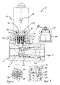
- Fig. 1 shows a device 2 according to the invention for measuring the volume or mass flow of a medium according to the differential pressure method.
- the device is designed as a flow measuring device with a Q-diagnostic measuring coupling and can be designed for different volume flows, for example 2 to 40 liters per minute, 5 to 100 liters per minute or 30 to 600 liters per minute.
- the device 2 according to the invention can be readily adapted to pressure ranges up to 650 bar.
- the illustrated device 2 is designed for liquid operating media, such as hydraulic oils, HFC fluids or water. Of course, the device can be used with advantage for gaseous media.
- the device 2 has a pressure-bearing housing part 4 through which the medium to be measured flows.
- a differential pressure channel 6, 8 are provided, via which a differential pressure sensor 10 can be acted upon by the differential pressure prevailing at the respective location.
- the differential pressure sensor 10 is designed to be removable from the pressure-bearing housing part 4.
- a connecting piece 12 is provided on the pressure-bearing housing part 4, which has a threaded connector 14 for fastening the differential pressure sensor 10.
- the differential pressure sensor 10 in turn has a union nut 16 by means of which a screw connection of the differential pressure sensor 10 with the threaded connector 14 of the connecting piece 12 of the housing part 4 is possible and a quick coupling is provided.
- the two differential pressure channels 6, 8 define a measuring section 18 along which a measurement of two effective pressures is made.
- One differential pressure channel 6 opens into a Venturi nozzle insert 20 provided in the pressure-bearing housing part 4, whereby a difference in the prevailing effective pressures which prevail in the differential pressure channels 6, 8 is achieved.
- the differential pressure is dependent on the volume or mass flow of the medium flowing through.
- differential pressure channels 6, 8 mechanically check valves 22, 24 are provided which lock the differential pressure sensor 10, the differential pressure channels 6, 8 and prevent leakage of the medium through the differential pressure channels 6, 8.
- the mechanically unlockable check valves 22, 24 are unlocked by the assembly of the differential pressure sensor 10.
- O-rings 36 are provided, which seal the hollow pin 30, 32 against the differential pressure channels 6, 8 and the union nut 16 against the connector 12.
- the seals 36 are arranged such that when connecting the differential pressure sensor 10, the sealing nipple 30, 32 come into operative position with the seals 36 before the check valves 22, 24 reach the open position.
- a fastened to the pressure-bearing housing part 4 screw cap 34 is used to seal the connector 12 with disassembled differential pressure sensor 10, see Fig. 4 ,
- the differential pressure sensor 10 is usually disassembled and stored separately.
- the screw cap 34 is, as in Fig. 4 shown screwed onto the threaded connector 14 of the connecting piece 12 of the pressure-bearing housing part 4.
- the differential pressure channels 6, 8 are closed by the check valves 22, 24.
- the screw cap 34 is unscrewed and the differential pressure sensor 10 is placed on the connector 12 and mounted by means of the union nut 16 on the threaded connector 14 of the connector 12.
- the hollow pins 30, 32 are inserted into the differential pressure channels 6, 8 and open with their end faces the check valves 22, 24, so that an operative connection between the measuring section 18 and sensor chambers 38 of the differential pressure sensor 10 is made.
- a sealing of the between the pressure differential channels 6, 8 and measuring channels 46, 48 of the differential pressure sensor 10 is achieved via the formed as O-rings seals 36. Afterwards the flow rate can be measured. In this case, the fluid is prevented from escaping during the assembly of the differential pressure sensor 10.
- Fig. 2 shows a section along the section line AA through the connection region of pressure-bearing housing part 4 and differential pressure sensor 10 according to Fig. 1 ,
- a coding pin 28 is provided in the illustrated cross-section, by means of which and the associated coding bore 26 is accomplished that the differential pressure sensor 10 can be mounted only in the correct position on the pressure-bearing housing part 4.
- the hollow pins 30, 32 and the coding pin 28 are not distributed symmetrically over the cross section for this purpose.
- Fig. 3 shows a further section through the device 2 in the connection area along the section line BB according to Fig. 2 ,
- the Kodierzapfen 28 in position, depth and diameter adapted Codierbohrung 26 is provided so that the Kodierzapfen 28 protrudes exactly into the Codierbohrung 26.
- the coding pin 28 is fixed in the differential pressure sensor 10.
- Fig. 4 shows the device 2 according to the invention with disassembled differential pressure sensor 10.
- the screw cap 34 is screwed onto the threaded connector 14.
- the check valves 22, 24 are closed.
- the screw cap 34 has a punch 42 with a seal.
- a locking ring is called, which allows the rotatability of the union nut 16 relative to the connecting piece 12 of the differential pressure sensor 10 when connecting and disconnecting.
- the screw cap 34 is also held by means of a locking ring 50 on the punch 42 rotatable.
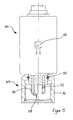
- Fig. 5 shows the differential pressure sensor 10 of the device 2 according to the invention separately.
- An opening fitting 44 formed from the already described components union nut 16, hollow pin 30, 32, Kodierzapfen 28, is shown in section.
- the hollow pins 30, 32 are fluidly connected to the sensor chambers 38.
- the sensor chambers 38 take on each hollow pin 30, 32 to a pressure and a pressure difference is determined.
- a usual differential pressure is between 0 and 2 bar, depending on the respective volume or mass flow and the specific configuration of the Venturidüsendones 20th
- the differential pressure can, for example, be transmitted electrically to an evaluation unit and / or displayed on the differential pressure sensor via suitable display means.
Abstract
Description
Die Erfindung betrifft eine Vorrichtung zur Messung des Volumen- oder Massestromes eines Mediums nach dem Wirkdruckverfahren, mit einem drucktragenden Gehäuseteil mit einer Messstrecke, in die wenigstens zwei Wirkdruckkanäle münden, wobei ein mit den Wirkdruckkanälen in Wirkverbindung bringbarer Differenzdrucksensor vorgesehen ist.The invention relates to a device for measuring the volume or mass flow of a medium according to the differential pressure method, with a pressure-bearing housing part with a measuring section, open into the at least two differential pressure channels, wherein a differential pressure sensor can be brought into operative connection with the differential pressure channels.
Zur Messung eines Volumen- und Massestroms sind im Stand der Technik verschiedene Vorrichtungen bekannt, die nach unterschiedlichen Wirkprinzipien arbeiten. Die Durchflussmessung nach dem Wirkdruckverfahren ist hierbei das am meisten angewandte Verfahren, unter anderem, da zur Messung des Volumen- oder Massestroms eines zu messenden Mediums keine bewegten Bauteile in den Strom eingebracht werden müssen.To measure a volume and mass flow, various devices are known in the prior art, which operate on different principles of action. The flow measurement according to the differential pressure method is the most widely used method, among other things, since no moving components have to be introduced into the stream for measuring the volume or mass flow of a medium to be measured.
Das Wirkdruckverfahren basiert auf der Messung wenigstens zweier Absolutdrücke, die in dem Fluidsystem herrschen, entlang einer Messstrecke. In der Messstrecke ist meist eine Vorrichtung vorgesehen, welche streckenweise den Strömungsquerschnitt verändert. Hierdurch wird eine von dem Volumen- oder Massestrom abhängige Druckdifferenz erzeugt, die als Messgröße herangezogen wird.The differential pressure method is based on the measurement of at least two absolute pressures that prevail in the fluid system along a measurement path. In the measuring section, a device is usually provided which changes the flow cross section in sections. As a result, a dependent of the volume or mass flow pressure difference is generated, which is used as a measured variable.
Eine Vorrichtung der eingangs genannten Art ist beispielsweise in der
Die Messanschlüsse sind als unter dem Betriebsdruck mit den Anschlüssen der Drucksensoren kuppelbare, gleichartige Kupplungen ausgebildet und die Drucksensoren mit einem prozessorgesteuerten Auswertegerät galvanisch verbunden. Als Drucksensoren werden einfache Drucksensoren verwendet.The measuring connections are designed as couplings which can be coupled to the connections of the pressure sensors under the operating pressure, and the pressure sensors are galvanically connected to a processor-controlled evaluation device. As pressure sensors simple pressure sensors are used.
Nachteilig hieran ist der erhöhte Montageaufwand, da zur Messung mehrerer Drucksensoren eingebaut und galvanisch mit einem Auswertegerät verbunden werden müssen. Darüber hinaus ist eine Eichung der Drucksensoren notwendig und damit auch eine Zuordnung eines bestimmten Drucksensors zu einem bestimmten Anschluss.The disadvantage of this is the increased installation costs, since installed to measure multiple pressure sensors and must be electrically connected to an evaluation device. In addition, a calibration of the pressure sensors is necessary and thus an assignment of a specific pressure sensor to a specific port.
Darüber hinaus sind Vorrichtungen der eingangs genannten Art mit sogenannten Differenzdrucksensoren bekannt. Die aus dem Stand der Technik bekannten Vorrichtungen zur Messung des Volumen- oder Massenstromes, die Differenzdrucksensoren verwenden, weisen jedoch den Nachteil auf, dass sie regelmäßig für den Festeinbau ausgebildet sind, sodass die bekannten Differenzdrucksensoren stets montiert sind. Differenzdrucksensoren sind jedoch vergleichsweise empfindlich und haben in vielen Maschinen aufgrund der dortigen Druckverhältnisse und mechanischen Belastungen eine geringe Standfestigkeit.In addition, devices of the type mentioned with so-called differential pressure sensors are known. However, the known from the prior art devices for measuring the volume or mass flow, the differential pressure sensors use, however, have the disadvantage that they are regularly designed for permanent installation, so that the known differential pressure sensors are always mounted. However, differential pressure sensors are relatively sensitive and have a low stability in many machines due to the pressure conditions and mechanical loads.
Aus diesem Grund ist im Stand der Technik weiterhin bekannt, die Vorrichtungen nur zur Durchführung einer Messung zu montieren, was jedoch den Nachteil hat, dass hierzu die Maschine angehalten werden muss, und dass beim Ein- und Ausbau der Vorrichtung das mediumtragende System geöffnet werden muss. Ein Austritt des Mediums, z.B. Öl, ist daher die Folge. Des Weiteren ist die Montage sehr aufwendig und wird daher in der Praxis häufig vermieden.For this reason, it is also known in the prior art to mount the devices only to perform a measurement, but this has the disadvantage that for this purpose the machine must be stopped, and that when mounting and dismounting the device, the medium-carrying system must be opened , An exit of the medium, e.g. Oil is therefore the result. Furthermore, the assembly is very expensive and is therefore often avoided in practice.
Aus
Hiervon ausgehend liegt der Erfindung die Aufgabe zugrunde, eine Vorrichtung der eingangs genannten Art dahingehend zu verbessern, dass sie die Nachteile des Standes der Technik überwindet und eine montage- und verfahrenstechnisch einfach durchzuführende Messung des Volumen- oder Massenstroms eines Mediums erlaubt.On this basis, the invention has the object to improve a device of the type mentioned in that it overcomes the disadvantages of the prior art and allows a montage and procedurally simple to perform measurement of the volume or mass flow of a medium.
Die Aufgabe wird gelöst durch eine Vorrichtung gemäß Anspruch 1 sowie eine Maschine gemäß dem nebengeordneten Anspruch 16. Vorteilhafte Ausgestaltungen der Erfindung sind Gegenstand der Unteransprüche.The object is achieved by a device according to claim 1 and a machine according to the
Eine erfindungsgemäße Vorrichtung zur Messung des Volumen- oder Massestromes eines Mediums, beispielsweise eines Fluids, wie Öl oder dergleichen, welche nach dem Wirkdruckverfahren arbeitet, weist ein drucktragendes Gehäuseteil mit einer Messstrecke auf, entlang derer mehrere Wirkdrücke gemessen werden. Zum Abgreifen der Wirkdrücke sind wenigstens zwei Wirkdruckkanäle vorgesehen, die in die Messstrecke münden. Zur Messung einer Wirkdruckdifferenz ist ein mit den Wirkdruckkanälen in Druckübertragungsverbindung bringbarer Differenzdrucksensor vorgesehen. Mit Hilfe des Differenzdrucksensors kann in an sich bekannter Weise eine Druckdifferenz entlang der Messstrecke festgestellt werden.A device according to the invention for measuring the volumetric or mass flow of a medium, for example a fluid, such as oil or the like, which operates according to the differential pressure method, has a pressure-bearing housing part with a measuring path, along which several effective pressures are measured. For tapping the effective pressures at least two differential pressure channels are provided, which open into the measuring section. To measure a differential pressure differential is provided with the Wirkdruckkanälen in pressure transmission connection differential pressure sensor. With the help of the differential pressure sensor, a pressure difference along the measuring section can be determined in a conventional manner.
Erfindungsgemäß ist vorgesehen, dass die Wirkdruckkanäle über eine gemeinsame Kupplung mit einer Gegenkupplung des Differenzdrucksensors verbindbar und dass Mittel zum lage- bzw. positionssicherem Anschließen der Wirkdruckkanäle mit dem Differenzdrucksensor vorgesehen sind. Der Differenzdrucksensor ist somit von dem drucktragenden Gehäuseteil in einfacher Weise abnehmbar und in gleicher Weise anschließbar. Damit wird der Vorteil erreicht, dass der Differenzdrucksensor nur dann an der Messstrecke montiert sein muss, wenn tatsächlich eine Messung vorgenommen wird. Gleichzeitig wird vermieden, dass zur Anbringung der Vorrichtung zur Messung der mediumführende Teil, dessen Volumen- oder Massenstrom an Medium gemessen werden soll, geöffnet werden muss. Auch ist durch die Erfindung vermieden, dass mehrere Einzelsensoren montiert werden müssen. Durch die Ausbildung von Mitteln zum lagesicheren Verbinden der Wirkdruckkanäle mit dem Drucksensor ist verhindert, dass die Sensoren in falscher Anordnung montiert werden und dadurch ein falsches Messergebnis erzeugt wird. Das drucktragende Gehäuse kann integraler bzw. fester Bestandteil einer Maschine oder Vorrichtung sein.According to the invention, it is provided that the differential pressure channels can be connected via a common coupling to a counter-coupling of the differential pressure sensor and that means for positionally or positionally reliable connection of the differential pressure channels with the differential pressure sensor are provided. The differential pressure sensor is thus removable from the pressure-bearing housing part in a simple manner and connectable in the same way. This will be the advantage ensures that the differential pressure sensor must be mounted on the measuring section only when a measurement is actually made. At the same time it is avoided that for attaching the device for measuring the medium-carrying part whose volume or mass flow of medium to be measured, must be opened. It is also avoided by the invention that several individual sensors must be mounted. By forming means for positionally secure connection of the differential pressure channels with the pressure sensor prevents the sensors are mounted in the wrong position and thereby a false measurement result is generated. The pressure-bearing housing may be an integral part of a machine or device.
Gemäß einer ersten Weiterbildung der Erfindung weist die Kupplung ein mit dem Gehäuseteil verbundenes, die Wirkdruckkanäle umfassendes Anschlussstück zum Anschluss des Differenzdrucksensors auf. Mit Hilfe des Anschlussstücks kann der Differenzdrucksensor besonders leicht an dem drucktragenden Gehäuseteil montiert werden.According to a first development of the invention, the coupling has a connecting piece connected to the housing part and comprising the differential pressure channels for connection of the differential pressure sensor. With the help of the connector, the differential pressure sensor can be mounted very easily on the pressure-bearing housing part.
Der Anschluss lässt sich montagetechnisch besonders einfach dann erreichen, wenn auch die Gegenkupplung ein die Messkanäle des Differenzdrucksensors umfassendes Gegenanschlussstück aufweist, so dass ein einfaches und schnelles Anschließen und Abnehmen des Differenzdrucksensors erreicht ist.The connection can be particularly easy to achieve assembly technology, even if the counter-coupling has a measuring channels of the differential pressure sensor comprehensive mating connector, so that a simple and fast connection and detachment of the differential pressure sensor is reached.
Besonders vorteilhaft ist es, wenn nach einer weiteren Ausführungsform der Erfindung Mittel zum Kuppeln der Wirkdruckkanäle mit dem Differenzdrucksensor unter Betriebsdruck vorgesehen sind. Hierdurch ist der Differenzdrucksensor an das drucktragende Gehäuseteil anschließbar oder auch abnehmbar, sodass es zu keinem Medium- oder Ölverlusten während des Anschließens und Abnehmens des Differenzdrucksensors kommt. Die Drucksensoren sind daher bei den jeweils geltenden Betriebsbedingungen bei beliebigem Referenzdruck sowohl in Nullabgleichschaltung als auch in Messstellung bringbar. Ein Anlagenstillstand bei Kuppeln oder Abnahme der Messvorrichtung tritt nicht ein.It is particularly advantageous if, according to a further embodiment of the invention, means for coupling the differential pressure channels to the differential pressure sensor are provided under operating pressure. As a result, the differential pressure sensor to the pressure-bearing housing part is connected or removable, so there is no loss of media or oil during the connection and removal of the differential pressure sensor. The pressure sensors can therefore be brought into the zero balancing circuit as well as into the measuring position under any given operating conditions at any reference pressure. A plant standstill with domes or decrease of the measuring device does not occur.
Gemäß einer weiteren Weiterbildung der Erfindung sind als Mittel zum Kuppeln der Wirkdruckkanäle Rückschlagventile vorgesehen, die bevorzugt mechanisch entsperrbar sind. Mit Hilfe derartiger Rückschlagventile kann die jeweilige Wirkdruckleitung besonders einfach abgesperrt werden, wenn kein Differenzdrucksensor montiert ist.According to a further development of the invention, check valves are provided as means for coupling the differential pressure channels, which are preferably mechanically unlockable. With the help of such check valves, the respective differential pressure line can be particularly easily shut off when no differential pressure sensor is mounted.
Wenn das oder die Rückschlagventile darüber hinaus mechanisch entsperrbar sind, kann eine Entsperrung des Rückschlagventils und damit eine Öffnung der Wirkdruckkanäle durch Montage des Durchflusssensors erreicht werden. Auf diese Weise lässt sich besonders einfach eine Wirkverbindung zwischen den Wirkdruckkanälen und dem Differenzdrucksensor erzielen. An dem Differenzdrucksensor ist daher die Öffnungsarmatur der Rückschlagventile als integraler Bestandteil angeordnet, was die Handhabung beim Anschließen und Abnehmen des Differenzdrucksensors nochmals vereinfacht.If the one or more non-return valves are also mechanically unlockable, an unlocking of the check valve and thus an opening of the differential pressure channels can be achieved by mounting the flow sensor. In this way it is particularly easy to achieve an operative connection between the differential pressure channels and the differential pressure sensor. At the differential pressure sensor, therefore, the opening fitting of the check valves is arranged as an integral part, which further simplifies handling when connecting and removing the differential pressure sensor.
Der Differenzdrucksensor weist gemäß einer Weiterbildung der Erfindung Dichtnippel auf, über die der Differenzdrucksensor in auf dem Gehäuseteil befestigter Stellung mit den Wirkdruckkanälen wirkverbindbar ist. Mit Hilfe der Dichtnippel lässt sich eine sichere Abdichtung der Verbindung zwischen Differenzdrucksensor und Wirkdruckkanälen erzielen.According to a development of the invention, the differential pressure sensor has sealing nipples via which the differential pressure sensor can be operatively connected to the differential pressure channels in a position fastened to the housing part. With the help of the sealing nipple, a secure sealing of the connection between differential pressure sensor and differential pressure channels can be achieved.
Die Dichtnippel sind bevorzugt als Hohlzapfen ausgebildet, die in Montagestellung des Differenzdrucksensors an der Messstrecke in das Anschlussstück des drucktragenden Gehäuseteils hineinragen. Hiermit lässt sich eine besonders gute Abdichtung der Anbindung erreichen.The sealing nipples are preferably designed as hollow pins, which protrude into the fitting of the pressure-bearing housing part in the mounting position of the differential pressure sensor on the measuring section. This makes it possible to achieve a particularly good sealing of the connection.
Wenn die Hohlzapfen darüber hinaus dazu ausgebildet sind, die gemäß der zuvor beschriebenen Weiterbildung vorgesehenen mechanisch entsperrbaren Rückschlagventile zu entsperren, lässt sich eine besonders einfache Montage des Differenzdrucksensors verwirklichen.If the hollow pins are furthermore designed to unlock the mechanically unlockable non-return valves provided according to the development described above, a particularly simple installation of the differential pressure sensor can be realized.
Des Weiteren ist zur Abdichtung von Gehäuseteil und Differenzdrucksensor in Montagestellung wenigstens ein O-Ring vorgesehen, der eine druckdichte Anbindung von Differenzdrucksensor am Gehäuseteil ermöglicht.Furthermore, to seal the housing part and differential pressure sensor in Mounting position provided at least one O-ring, which allows a pressure-tight connection of differential pressure sensor on the housing part.
Dabei sind die vorzugsweise als O-Ringe ausgebildeten Dichtungen derart angeordnet, dass beim Anschließen des Differenzdrucksensors die Dichtnippel mit den gehäuseseitigen Dichtungen in Wirkstellung treten, bevor die Rückschlagventile in Öffnungsstellung gelangen. Dies erweist sich als besonders effektive und konstruktiv vorteilhafte Maßnahme, um das Kuppeln der Wirkdruckkanäle mit dem Differenzdrucksensor unter Betriebsdruck vornehmen zu können. Sowohl beim Ankuppeln als auch bei Abnahme der Messvorrichtung tritt kein Anlagenstillstand ein. Ein Medium- oder Ölverlust während der Ein- und Ausbauarbeiten des Differenzdrucksensors tritt damit nicht mehr auf.The preferably designed as O-rings seals are arranged such that when connecting the differential pressure sensor, the sealing nipple with the housing-side seals in operative position before the check valves reach the open position. This proves to be a particularly effective and structurally advantageous measure to be able to make the coupling of the differential pressure channels with the differential pressure sensor under operating pressure. Both when coupling and when taking the measuring device no plant standstill occurs. A medium or oil loss during installation and removal of the differential pressure sensor thus no longer occurs.
Gemäß einer Weiterbildung der Erfindung weist das Anschlussstück einen Gewindestutzen und der Differenzdrucksensor eine Überwurfmutter auf, mit Hilfe derer der Differenzdrucksensor an dem Anschlussstück befestigt wird. Eine derartige Schnellkupplung ermöglicht eine einfache und druckdichte Befestigung des Differenzdrucksensors.According to one embodiment of the invention, the connector has a threaded connector and the differential pressure sensor to a union nut, by means of which the differential pressure sensor is attached to the connector. Such a quick coupling allows a simple and pressure-tight attachment of the differential pressure sensor.
Weiterhin kann gemäß einer Weiterbildung vorgesehen sein, dass die Mittel zum lagerichtigen Verbinden der Wirkdruckkanäle mit dem Differenzdrucksensor mindestens eine Bohrung und einen damit verbindbaren Zapfen aufweisen. Hiermit lässt sich sicherstellen, dass der Differenzdrucksensor in der richtigen Ausrichtung montiert wird.Furthermore, it can be provided according to a development that the means for the correct position connecting the differential pressure channels with the differential pressure sensor have at least one bore and a pin connectable thereto. This ensures that the differential pressure sensor is mounted in the correct orientation.
Bevorzugte Mittel hierzu sind wenigstens eine Kodierbohrung und ein Kodierzapfen, wobei die Kodierbohrung in dem drucktragenden Gehäuseteil oder in dem Differenzdrucksensor vorgesehen sein kann und der Kodierzapfen in dem jeweils anderen Bauteil. Eine besonders bevorzugte Ausführungsform sieht die Anordnung der Kodierbohrung in dem drucktragenden Gehäuseteil sowie die des Kodierzapfens in dem Differenzdrucksensor vor.Preferred means for this purpose are at least one Codierbohrung and a Kodierzapfen, wherein the Codierbohrung can be provided in the pressure-bearing housing part or in the differential pressure sensor and the coding pin in the respective other component. A particularly preferred embodiment provides for the arrangement of the coding bore in the pressure-bearing housing part and that of the coding pin in the differential pressure sensor.
Zum Schutz des drucktragenden Gehäuseteils bei abgenommenen Differenzdrucksensor ist bevorzugt eine Schraubkappe vorgesehen, die den Anschlussbereich zum Differenzdrucksensor abschließt. Hierdurch lässt sich eine mechanische Beschädigung sowie eine Verschmutzung des Anschlussbereichs verhindern.To protect the pressure-bearing housing part with the differential pressure sensor removed, a screw cap is preferably provided, which terminates the connection region to the differential pressure sensor. This can prevent mechanical damage and contamination of the connection area.
Bevorzugt weist das drucktragende Gehäuseteil einen Düseneinsatz auf, wobei der eine Wirkdruckkanal im Bereich des Düseneinsatzes in die Messstrecke mündet.The pressure-bearing housing part preferably has a nozzle insert, wherein the one pressure-pressure channel opens into the measuring section in the region of the nozzle insert.
Der Düseneinsatz ist bevorzugt als Venturidüseneinsatz ausgebildet. Der Düseneinsatz kann einstückig in dem Gehäuseteil vorgesehen sein oder als austauschbarer Düseneinsatz.The nozzle insert is preferably designed as Venturi nozzle insert. The nozzle insert may be integrally provided in the housing part or as an exchangeable nozzle insert.
Der Differenzdrucksensor weist wenigstens zwei mit den wenigstens zwei Wirkdruckkanälen verbindbare Sensorkammern auf. Auf diese Weise lässt sich der Differenzdruck entlang der Messstrecke besonders einfach feststellen.The differential pressure sensor has at least two sensor chambers connectable to the at least two differential pressure channels. In this way, the differential pressure along the measuring section can be determined particularly easily.
Ein weiterer unabhängiger Gegenstand betrifft eine Maschine mit einer Vorrichtung gemäß der zuvor beschriebenen Erfindung. Eine derartige Maschine erlaubt die einfache Überwachung der mediumführenden Systeme im laufenden Betrieb mit hoher Zuverlässigkeit.Another independent subject relates to a machine having a device according to the invention described above. Such a machine allows easy monitoring of the media-carrying systems during operation with high reliability.
Weitere Ziele, Merkmale sowie vorteilhafte Anwendungsmöglichkeiten der Erfindung ergeben sich aus der nachfolgenden Beschreibung eines Ausführungsbeispiels anhand der Zeichnungen. Dabei bilden sämtliche beschriebenen und/oder bildlich dargestellten Merkmale in ihrer sinnvollen Kombination den Gegenstand der vorliegenden Erfindung, auch unabhängig von den Patentansprüchen und deren Rückbezügen.Other objects, features and advantageous applications of the invention will become apparent from the following description of an embodiment with reference to the drawings. All described and / or illustrated features in their meaningful combination form the subject of the present invention, also independent of the claims and their back references.
Die Erfindung wird anhand eines Ausführungsbeispiels erläutert. Dabei zeigen schematisch:
- Fig. 1
- eine erfindungsgemäße Vorrichtung mit montiertem Differenzdrucksensor;
- Fig. 2
- einen Schnitt durch die Vorrichtung entlang der Schnittlinie A-A gemäß
Fig. 1 ; - Fig. 3
- einen Schnitt durch die erfindungsgemäße Vorrichtung entlang der Schnittlinie B-B gemäß
Fig. 2 ; - Fig. 4
- ein drucktragendes Gehäuseteil der Vorrichtung ohne montiertem Differenzdrucksensor sowie
- Fig. 5
- ein Differenzdrucksensor gemäß der Erfindung.
- Fig. 1
- a device according to the invention with mounted differential pressure sensor;
- Fig. 2
- a section through the device along the section line AA according to
Fig. 1 ; - Fig. 3
- a section through the device according to the invention along the section line BB according to
Fig. 2 ; - Fig. 4
- a pressure-bearing housing part of the device without mounted differential pressure sensor and
- Fig. 5
- a differential pressure sensor according to the invention.
Die erfindungsgemäße Vorrichtung 2 weist ein drucktragendes Gehäuseteil 4 auf, durch das das zu messende Medium fließt. Zur Messung zweier Wirkdrücke sind zwei Wirkdruckkanäle 6, 8 vorgesehen, über die ein Differenzdrucksensor 10 mit den am jeweiligen Ort herrschenden Wirkdruck beaufschlagbar ist.The
Der Differenzdrucksensor 10 ist von dem drucktragenden Gehäuseteil 4 abnehmbar gestaltet. Zur Montage des Differenzdrucksensors 10 ist an dem drucktragenden Gehäuseteil 4 ein Anschlussstück 12 vorgesehen, das zur Befestigung des Differenzdrucksensors 10 einen Gewindestutzen 14 aufweist. Der Differenzdrucksensor 10 weist seinerseits eine Überwurfmutter 16 auf, mit Hilfe derer eine Schraubverbindung des Differenzdrucksensors 10 mit dem Gewindestutzen 14 des Anschlussstücks 12 des Gehäuseteils 4 möglich und eine Schnellkupplung zur Verfügung gestellt ist.The
Die beiden Wirkdruckkanäle 6, 8 definieren eine Messstrecke 18, entlang derer eine Messung zweier Wirkdrücke vorgenommen wird. Der eine Wirkdruckkanal 6 mündet dabei in einem in dem drucktragenden Gehäuseteil 4 vorgesehenen Venturidüseneinsatz 20, wodurch ein Unterschied in den herrschenden Wirkdrücken, die in den Wirkdruckkanälen 6, 8 herrschen, erzielt wird. Die Wirkdruckdifferenz ist von dem Volumen- bzw. Massenstrom des durchfließenden Mediums abhängig.The two
In den Wirkdruckkanälen 6, 8 sind mechanisch entsperrbare Rückschlagventile 22, 24 vorgesehen, die bei demontiertem Differenzdrucksensor 10 die Wirkdruckkanäle 6, 8 sperren und einen Austritt des Mediums über die Wirkdruckkanäle 6, 8 verhindern. Die mechanisch entsperrbaren Rückschlagventile 22, 24 werden durch die Montage des Differenzdrucksensors 10 entsperrt.In the
Zum Anschluss des Differenzdrucksensors 10 und zum Entsperren der Rückschlagventile 22, 24 sind an dem Differenzdrucksensor 10 Hohlzapfen 30, 32 vorgesehen, die in die Wirkdruckkanäle 6, 8 hineinragen und die mit ihren Stirnseiten die Rückschlagventile 22, 24 in Öffnungsstellung betätigen. Auf diese Weise ist jeweils eine Wirkverbindung zwischen den Wirkdruckkanälen 6, 8 und dem Differenzdrucksensor 10 hergestellt.To connect the
Zur Abdichtung der Verbindung zwischen Differenzdrucksensor 10 und drucktragendem Gehäuseteil 4 sind O-Ringe 36 vorgesehen, die die Hohlzapfen 30, 32 gegen die Wirkdruckkanäle 6, 8 und die Überwurfmutter 16 gegen das Anschlussstück 12 abdichten. Die Dichtungen 36 sind derart angeordnet, dass beim Anschließen des Differenzdrucksensors 10 die Dichtnippel 30, 32 mit den Dichtungen 36 in Wirkstellung treten, bevor die Rückschlagventile 22, 24 in Öffnungsstellung gelangen.For sealing the connection between
Eine an dem drucktragenden Gehäuseteil 4 befestigte Schraubkappe 34 dient zum Abdichten des Anschlussstücks 12 bei demontiertem Differerenzdrucksensor 10, siehe hierzu
Im Betrieb einer Maschine, in der die erfindungsgemäße Vorrichtung 2 angeordnet ist, ist der Differenzdrucksensor 10 im Regelfalle demontiert und wird separat aufbewahrt. Die Schraubkappe 34 ist, wie in
Ist eine Messung des Volumen- oder Massenstroms des Mediums gewünscht, wird die Schraubkappe 34 abgeschraubt und der Differenzdrucksensor 10 auf das Anschlussstück 12 aufgesetzt und mittels der Überwurfmutter 16 an dem Gewindestutzen 14 des Anschlussstücks 12 montiert. Die Hohlzapfen 30, 32 werden in die Wirkdruckkanäle 6, 8 eingeführt und öffnen mit ihren Stirnseiten die Rückschlagventile 22, 24, sodass eine Wirkverbindung zwischen der Messstrecke 18 und Sensorkammern 38 des Differenzdrucksensors 10 hergestellt ist. Dabei wird über die als O-Ringe ausgebildeten Dichtungen 36 eine Abdichtung der zwischen Wirkdruckkanäle 6, 8 und Messkanäle 46, 48 des Differenzdrucksensors 10 erreicht. Im Anschluss kann die Durchflussmenge gemessen werden. Hierbei wird verhindert, dass das Fluid bei der Montage des Differenzdrucksensors 10 austritt.If a measurement of the volume or mass flow of the medium is desired, the
Nach erfolgter Messung wird der Differenzdrucksensor 10 wieder abgenommen, die Rückschlagventile 22, 24 sperren automatisch und die Schraubkappe 34 wird aufgesetzt.After the measurement, the
Neben den Hohlzapfen 30, 32 ist in dem dargestellten Querschnitt ein Kodierzapfen 28 vorgesehen, mit Hilfe dessen sowie der dazugehörigen Kodierbohrung 26 bewerkstelligt wird, dass der Differenzdrucksensor 10 ausschließlich lagerichtig auf dem drucktragenden Gehäuseteil 4 montiert werden kann. Die Hohlzapfen 30, 32 und der Kodierzapfen 28 sind hierzu nicht symmetrisch über den Querschnitt verteilt.In addition to the
In dem Anschlussstück 12 ist die dem Kodierzapfen 28 in Lage, Tiefe und Durchmesser angepasste Kodierbohrung 26 vorgesehen, sodass der Kodierzapfen 28 exakt in die Kodierbohrung 26 hineinragt. Der Kodierzapfen 28 ist in dem Differenzdrucksensor 10 festgelegt.In the connecting
Mit 50 ist ein Sicherungsring bezeichnet, der die Verdrehbarkeit der Überwurfmutter 16 gegenüber dem Anschlussstück 12 des Differenzdrucksensors 10 beim An- und Entkuppeln ermöglicht. Die Schraubkappe 34 ist ebenfalls mittels eines Sicherungsringes 50 an dem Stempel 42 verdrehbar gehalten.With 50 a locking ring is called, which allows the rotatability of the
Eine Öffnungsarmatur 44, gebildet aus den bereits beschriebenen Bestandteilen Überwurfmutter 16, Hohlzapfen 30, 32, Kodierzapfen 28, ist dabei im Schnitt dargestellt.An
Die Hohlzapfen 30, 32 sind mit den Sensorkammern 38 strömungsverbunden. Die Sensorkammern 38 nehmen über jeden Hohlzapfen 30, 32 einen Druck auf und eine Druckdifferenz wird ermittelt.The hollow pins 30, 32 are fluidly connected to the
Ein üblicher Differenzdruck liegt zwischen 0 und 2 bar, abhängig von dem jeweiligen Volumen- bzw. Massenstrom und der konkreten Ausgestaltung des Venturidüseneinsatzes 20.A usual differential pressure is between 0 and 2 bar, depending on the respective volume or mass flow and the specific configuration of the Venturidüseneinsatzes 20th
Der Differenzdruck kann in unterschiedlichen Ausführungsformen z.B. elektrisch an eine Auswerteeinheit weitergegeben werden und/oder auf dem Differenzdrucksensor über geeignete Anzeigemittel angezeigt werden.In different embodiments, the differential pressure can, for example, be transmitted electrically to an evaluation unit and / or displayed on the differential pressure sensor via suitable display means.
- 22
- Vorrichtungcontraption
- 44
- Drucktragendes GehäuseteilPressure-bearing housing part
- 66
- WirkdruckkanalEffective pressure duct
- 88th
- WirkdruckkanalEffective pressure duct
- 1010
- DifferenzdrucksensorDifferential Pressure Sensor
- 1212
- Anschlussstückconnector
- 1414
- Gewindestutzenthreaded connector
- 1616
- ÜberwurfmutterNut
- 1818
- Messstreckemeasuring distance
- 2020
- VenturidüseneinsatzVenturi nozzle insert
- 2222
- Rückschlagventilcheck valve
- 2424
- Rückschlagventilcheck valve
- 2626
- KodierbohrungKodierbohrung
- 2828
- Kodierzapfencoding pin
- 3030
- Hohlzapfenhollow pin
- 3232
- Hohlzapfenhollow pin
- 3434
- Schraubkappescrew cap
- 3636
- Dichtungpoetry
- 3838
- Sensorkammernsensor chambers
- 4040
- Sicherungsringcirclip
- 4242
- Stempelstamp
- 4444
- Öffnungsarmaturopening fixture
- 4646
- Messkanalmeasuring channel
- 4848
- Messkanalmeasuring channel
- 5050
- Sicherungsringcirclip
Claims (15)
Applications Claiming Priority (1)
| Application Number | Priority Date | Filing Date | Title |
|---|---|---|---|
| DE102009017335A DE102009017335A1 (en) | 2009-04-14 | 2009-04-14 | Device for measuring the volume or mass flow of a medium, machine with appropriate device |
Publications (3)
| Publication Number | Publication Date |
|---|---|
| EP2241864A2 true EP2241864A2 (en) | 2010-10-20 |
| EP2241864A3 EP2241864A3 (en) | 2012-01-11 |
| EP2241864B1 EP2241864B1 (en) | 2018-08-08 |
Family
ID=42404900
Family Applications (1)
| Application Number | Title | Priority Date | Filing Date |
|---|---|---|---|
| EP10003843.9A Active EP2241864B1 (en) | 2009-04-14 | 2010-04-10 | Device for measuring the flowrate of a fluid by means of a pressure difference sensor with corresponding connecting means for the sensor |
Country Status (3)
| Country | Link |
|---|---|
| EP (1) | EP2241864B1 (en) |
| DE (1) | DE102009017335A1 (en) |
| ES (1) | ES2693435T3 (en) |
Cited By (1)
| Publication number | Priority date | Publication date | Assignee | Title |
|---|---|---|---|---|
| CN105547573A (en) * | 2016-02-19 | 2016-05-04 | 中煤科工集团重庆研究院有限公司 | V-shaped tubular inclined micromanometer and measuring method thereof |
Families Citing this family (2)
| Publication number | Priority date | Publication date | Assignee | Title |
|---|---|---|---|---|
| DE102012106037B4 (en) | 2012-07-05 | 2017-11-23 | Stephan Wille | Coupling system with electronically controlled separation |
| DE202015100728U1 (en) | 2015-02-16 | 2015-03-06 | Parker Hannifin Manufacturing Germany GmbH & Co. KG | Measuring coupling with an RFID transponder |
Citations (2)
| Publication number | Priority date | Publication date | Assignee | Title |
|---|---|---|---|---|
| DE3710968C2 (en) | 1987-04-01 | 1989-12-07 | Hydrotechnik Gmbh, 6250 Limburg, De | |
| DE69629388T2 (en) | 1995-12-20 | 2004-07-01 | The Dow Chemical Co., Midland | METHOD FOR INSTALLING A PRESSURE DIFFERENTIAL CONVERTER |
Family Cites Families (9)
| Publication number | Priority date | Publication date | Assignee | Title |
|---|---|---|---|---|
| US1858399A (en) * | 1928-05-21 | 1932-05-17 | Jones Barton | Flow-meter construction |
| US3431935A (en) * | 1965-10-23 | 1969-03-11 | Foxboro Co | Apparatus for use in the measurement of fluid flow |
| US4582089A (en) * | 1984-10-31 | 1986-04-15 | General Screw Products Company | Valve manifold having a removable flange |
| DD239665A1 (en) * | 1985-07-23 | 1986-10-01 | Dessau Gas & Elektrogeraete | OVERPRESSURE PROTECTION, ESPECIALLY FOR ELECTRONIC FLOWMETERS |
| ATE55467T1 (en) * | 1986-02-17 | 1990-08-15 | Hydrotechnik Gmbh | FLUIDIC SYSTEM WITH MEASUREMENT DEVICE. |
| JPH0255123U (en) * | 1988-10-12 | 1990-04-20 | ||
| US6324917B1 (en) * | 1999-03-11 | 2001-12-04 | Mark Products, Inc. | Combination air pipe connector and flow measurement device |
| US6311568B1 (en) * | 1999-09-13 | 2001-11-06 | Rosemount, Inc. | Process flow device with improved pressure measurement feature |
| DE20305230U1 (en) * | 2003-04-01 | 2003-06-18 | Festo Ag & Co | Flow meter device |
-
2009
- 2009-04-14 DE DE102009017335A patent/DE102009017335A1/en not_active Withdrawn
-
2010
- 2010-04-10 EP EP10003843.9A patent/EP2241864B1/en active Active
- 2010-04-10 ES ES10003843.9T patent/ES2693435T3/en active Active
Patent Citations (2)
| Publication number | Priority date | Publication date | Assignee | Title |
|---|---|---|---|---|
| DE3710968C2 (en) | 1987-04-01 | 1989-12-07 | Hydrotechnik Gmbh, 6250 Limburg, De | |
| DE69629388T2 (en) | 1995-12-20 | 2004-07-01 | The Dow Chemical Co., Midland | METHOD FOR INSTALLING A PRESSURE DIFFERENTIAL CONVERTER |
Cited By (1)
| Publication number | Priority date | Publication date | Assignee | Title |
|---|---|---|---|---|
| CN105547573A (en) * | 2016-02-19 | 2016-05-04 | 中煤科工集团重庆研究院有限公司 | V-shaped tubular inclined micromanometer and measuring method thereof |
Also Published As
| Publication number | Publication date |
|---|---|
| ES2693435T3 (en) | 2018-12-11 |
| EP2241864A3 (en) | 2012-01-11 |
| EP2241864B1 (en) | 2018-08-08 |
| DE102009017335A1 (en) | 2010-10-28 |
Similar Documents
| Publication | Publication Date | Title |
|---|---|---|
| DE3638604A1 (en) | Fluidic system with volume flow measuring arrangement | |
| EP2241864B1 (en) | Device for measuring the flowrate of a fluid by means of a pressure difference sensor with corresponding connecting means for the sensor | |
| WO1999050584A1 (en) | Device for subsequently installing a fluid meter in a pipeline | |
| EP0902722B1 (en) | Device for controlling, guiding, adjusting, measuring and monitoring liquid flows, and water treatment facility | |
| EP3309528B1 (en) | Tube diaphragm seal | |
| DE102010032575A1 (en) | Sealing element for fitting between two flanges of flange coupling for piping arrangement, has flat, annular section for sealing flange coupling, where lateral handling attachment piece is attached to section | |
| WO2022043106A1 (en) | Compressed gas filter with through-opening in the housing head | |
| DE202016101941U1 (en) | Reducer assembly | |
| DE962485C (en) | Shut-off device in which the inlet line and outlet line are arranged concentrically or directly next to one another | |
| DE102019001742A1 (en) | Device for measuring and / or regulating and methods | |
| DE10227373B4 (en) | Tubular pitot tube | |
| DE102014005783A1 (en) | Connecting device for making a connection between a meter / valve block and a pipeline | |
| DE2712953A1 (en) | Gas pipe blocking device - comprises inflatable balloon containing pressure control instruments and instruments on either side | |
| DE19829969A1 (en) | Arrangement for checking the sealing of sleeve coupling regions of waste water pipes or channels | |
| DE102016005040A1 (en) | Flow meter for a cooling medium | |
| DE202016102759U1 (en) | shut-off | |
| DE112017000314T5 (en) | Indicating wafer sieve | |
| DE2929480A1 (en) | Rotating valve sphere in on=off valve - provides filter location in transfer hole for removal of solid matter from fluid | |
| WO2009015819A2 (en) | Liquid consumption meter | |
| DE4007278A1 (en) | Connecting fixture for single branch gas meter - has connecting piece with short feed pipes for meter, consumer and stop cock and is accommodated in building service box | |
| EP4191111A1 (en) | Media guiding coupling and media guidance | |
| DE202021102566U1 (en) | System with one check valve and with different inserts for the check valve | |
| EP2561258B9 (en) | Shut-off valve with a block- and bleed-device | |
| DE102020213512A1 (en) | Measuring device with pitot flow meter and method for its manufacture | |
| EP3441659A1 (en) | Connection fitting for a fluid conduit |
Legal Events
| Date | Code | Title | Description |
|---|---|---|---|
| PUAI | Public reference made under article 153(3) epc to a published international application that has entered the european phase |
Free format text: ORIGINAL CODE: 0009012 |
|
| AK | Designated contracting states |
Kind code of ref document: A2 Designated state(s): AT BE BG CH CY CZ DE DK EE ES FI FR GB GR HR HU IE IS IT LI LT LU LV MC MK MT NL NO PL PT RO SE SI SK SM TR |
|
| AX | Request for extension of the european patent |
Extension state: AL BA ME RS |
|
| PUAL | Search report despatched |
Free format text: ORIGINAL CODE: 0009013 |
|
| AK | Designated contracting states |
Kind code of ref document: A3 Designated state(s): AT BE BG CH CY CZ DE DK EE ES FI FR GB GR HR HU IE IS IT LI LT LU LV MC MK MT NL NO PL PT RO SE SI SK SM TR |
|
| AX | Request for extension of the european patent |
Extension state: AL BA ME RS |
|
| RIC1 | Information provided on ipc code assigned before grant |
Ipc: G01F 15/18 20060101ALI20111205BHEP Ipc: G01F 1/44 20060101AFI20111205BHEP Ipc: G01F 1/36 20060101ALI20111205BHEP |
|
| 17P | Request for examination filed |
Effective date: 20120224 |
|
| 17Q | First examination report despatched |
Effective date: 20141030 |
|
| GRAP | Despatch of communication of intention to grant a patent |
Free format text: ORIGINAL CODE: EPIDOSNIGR1 |
|
| STAA | Information on the status of an ep patent application or granted ep patent |
Free format text: STATUS: GRANT OF PATENT IS INTENDED |
|
| INTG | Intention to grant announced |
Effective date: 20180222 |
|
| GRAS | Grant fee paid |
Free format text: ORIGINAL CODE: EPIDOSNIGR3 |
|
| GRAA | (expected) grant |
Free format text: ORIGINAL CODE: 0009210 |
|
| STAA | Information on the status of an ep patent application or granted ep patent |
Free format text: STATUS: THE PATENT HAS BEEN GRANTED |
|
| AK | Designated contracting states |
Kind code of ref document: B1 Designated state(s): AT BE BG CH CY CZ DE DK EE ES FI FR GB GR HR HU IE IS IT LI LT LU LV MC MK MT NL NO PL PT RO SE SI SK SM TR |
|
| REG | Reference to a national code |
Ref country code: GB Ref legal event code: FG4D Free format text: NOT ENGLISH |
|
| REG | Reference to a national code |
Ref country code: CH Ref legal event code: EP Ref country code: AT Ref legal event code: REF Ref document number: 1027539 Country of ref document: AT Kind code of ref document: T Effective date: 20180815 |
|
| REG | Reference to a national code |
Ref country code: IE Ref legal event code: FG4D Free format text: LANGUAGE OF EP DOCUMENT: GERMAN |
|
| REG | Reference to a national code |
Ref country code: DE Ref legal event code: R096 Ref document number: 502010015222 Country of ref document: DE |
|
| REG | Reference to a national code |
Ref country code: CH Ref legal event code: NV Representative=s name: DENNEMEYER AG, CH |
|
| REG | Reference to a national code |
Ref country code: NL Ref legal event code: FP |
|
| REG | Reference to a national code |
Ref country code: SE Ref legal event code: TRGR |
|
| REG | Reference to a national code |
Ref country code: ES Ref legal event code: FG2A Ref document number: 2693435 Country of ref document: ES Kind code of ref document: T3 Effective date: 20181211 |
|
| REG | Reference to a national code |
Ref country code: LT Ref legal event code: MG4D |
|
| REG | Reference to a national code |
Ref country code: NO Ref legal event code: T2 Effective date: 20180808 |
|
| PG25 | Lapsed in a contracting state [announced via postgrant information from national office to epo] |
Ref country code: BG Free format text: LAPSE BECAUSE OF FAILURE TO SUBMIT A TRANSLATION OF THE DESCRIPTION OR TO PAY THE FEE WITHIN THE PRESCRIBED TIME-LIMIT Effective date: 20181108 Ref country code: IS Free format text: LAPSE BECAUSE OF FAILURE TO SUBMIT A TRANSLATION OF THE DESCRIPTION OR TO PAY THE FEE WITHIN THE PRESCRIBED TIME-LIMIT Effective date: 20181208 Ref country code: PL Free format text: LAPSE BECAUSE OF FAILURE TO SUBMIT A TRANSLATION OF THE DESCRIPTION OR TO PAY THE FEE WITHIN THE PRESCRIBED TIME-LIMIT Effective date: 20180808 Ref country code: LT Free format text: LAPSE BECAUSE OF FAILURE TO SUBMIT A TRANSLATION OF THE DESCRIPTION OR TO PAY THE FEE WITHIN THE PRESCRIBED TIME-LIMIT Effective date: 20180808 Ref country code: GR Free format text: LAPSE BECAUSE OF FAILURE TO SUBMIT A TRANSLATION OF THE DESCRIPTION OR TO PAY THE FEE WITHIN THE PRESCRIBED TIME-LIMIT Effective date: 20181109 Ref country code: FI Free format text: LAPSE BECAUSE OF FAILURE TO SUBMIT A TRANSLATION OF THE DESCRIPTION OR TO PAY THE FEE WITHIN THE PRESCRIBED TIME-LIMIT Effective date: 20180808 |
|
| PG25 | Lapsed in a contracting state [announced via postgrant information from national office to epo] |
Ref country code: LV Free format text: LAPSE BECAUSE OF FAILURE TO SUBMIT A TRANSLATION OF THE DESCRIPTION OR TO PAY THE FEE WITHIN THE PRESCRIBED TIME-LIMIT Effective date: 20180808 Ref country code: HR Free format text: LAPSE BECAUSE OF FAILURE TO SUBMIT A TRANSLATION OF THE DESCRIPTION OR TO PAY THE FEE WITHIN THE PRESCRIBED TIME-LIMIT Effective date: 20180808 |
|
| PG25 | Lapsed in a contracting state [announced via postgrant information from national office to epo] |
Ref country code: EE Free format text: LAPSE BECAUSE OF FAILURE TO SUBMIT A TRANSLATION OF THE DESCRIPTION OR TO PAY THE FEE WITHIN THE PRESCRIBED TIME-LIMIT Effective date: 20180808 Ref country code: CZ Free format text: LAPSE BECAUSE OF FAILURE TO SUBMIT A TRANSLATION OF THE DESCRIPTION OR TO PAY THE FEE WITHIN THE PRESCRIBED TIME-LIMIT Effective date: 20180808 Ref country code: RO Free format text: LAPSE BECAUSE OF FAILURE TO SUBMIT A TRANSLATION OF THE DESCRIPTION OR TO PAY THE FEE WITHIN THE PRESCRIBED TIME-LIMIT Effective date: 20180808 |
|
| REG | Reference to a national code |
Ref country code: DE Ref legal event code: R097 Ref document number: 502010015222 Country of ref document: DE |
|
| PG25 | Lapsed in a contracting state [announced via postgrant information from national office to epo] |
Ref country code: DK Free format text: LAPSE BECAUSE OF FAILURE TO SUBMIT A TRANSLATION OF THE DESCRIPTION OR TO PAY THE FEE WITHIN THE PRESCRIBED TIME-LIMIT Effective date: 20180808 Ref country code: SM Free format text: LAPSE BECAUSE OF FAILURE TO SUBMIT A TRANSLATION OF THE DESCRIPTION OR TO PAY THE FEE WITHIN THE PRESCRIBED TIME-LIMIT Effective date: 20180808 Ref country code: SK Free format text: LAPSE BECAUSE OF FAILURE TO SUBMIT A TRANSLATION OF THE DESCRIPTION OR TO PAY THE FEE WITHIN THE PRESCRIBED TIME-LIMIT Effective date: 20180808 |
|
| PLBE | No opposition filed within time limit |
Free format text: ORIGINAL CODE: 0009261 |
|
| STAA | Information on the status of an ep patent application or granted ep patent |
Free format text: STATUS: NO OPPOSITION FILED WITHIN TIME LIMIT |
|
| 26N | No opposition filed |
Effective date: 20190509 |
|
| PG25 | Lapsed in a contracting state [announced via postgrant information from national office to epo] |
Ref country code: SI Free format text: LAPSE BECAUSE OF FAILURE TO SUBMIT A TRANSLATION OF THE DESCRIPTION OR TO PAY THE FEE WITHIN THE PRESCRIBED TIME-LIMIT Effective date: 20180808 |
|
| REG | Reference to a national code |
Ref country code: BE Ref legal event code: MM Effective date: 20190430 |
|
| PG25 | Lapsed in a contracting state [announced via postgrant information from national office to epo] |
Ref country code: LU Free format text: LAPSE BECAUSE OF NON-PAYMENT OF DUE FEES Effective date: 20190410 Ref country code: MC Free format text: LAPSE BECAUSE OF FAILURE TO SUBMIT A TRANSLATION OF THE DESCRIPTION OR TO PAY THE FEE WITHIN THE PRESCRIBED TIME-LIMIT Effective date: 20180808 |
|
| PG25 | Lapsed in a contracting state [announced via postgrant information from national office to epo] |
Ref country code: BE Free format text: LAPSE BECAUSE OF NON-PAYMENT OF DUE FEES Effective date: 20190430 |
|
| PG25 | Lapsed in a contracting state [announced via postgrant information from national office to epo] |
Ref country code: TR Free format text: LAPSE BECAUSE OF FAILURE TO SUBMIT A TRANSLATION OF THE DESCRIPTION OR TO PAY THE FEE WITHIN THE PRESCRIBED TIME-LIMIT Effective date: 20180808 |
|
| PG25 | Lapsed in a contracting state [announced via postgrant information from national office to epo] |
Ref country code: IE Free format text: LAPSE BECAUSE OF NON-PAYMENT OF DUE FEES Effective date: 20190410 |
|
| PG25 | Lapsed in a contracting state [announced via postgrant information from national office to epo] |
Ref country code: PT Free format text: LAPSE BECAUSE OF FAILURE TO SUBMIT A TRANSLATION OF THE DESCRIPTION OR TO PAY THE FEE WITHIN THE PRESCRIBED TIME-LIMIT Effective date: 20181208 |
|
| PG25 | Lapsed in a contracting state [announced via postgrant information from national office to epo] |
Ref country code: CY Free format text: LAPSE BECAUSE OF FAILURE TO SUBMIT A TRANSLATION OF THE DESCRIPTION OR TO PAY THE FEE WITHIN THE PRESCRIBED TIME-LIMIT Effective date: 20180808 |
|
| PG25 | Lapsed in a contracting state [announced via postgrant information from national office to epo] |
Ref country code: MT Free format text: LAPSE BECAUSE OF FAILURE TO SUBMIT A TRANSLATION OF THE DESCRIPTION OR TO PAY THE FEE WITHIN THE PRESCRIBED TIME-LIMIT Effective date: 20180808 Ref country code: HU Free format text: LAPSE BECAUSE OF FAILURE TO SUBMIT A TRANSLATION OF THE DESCRIPTION OR TO PAY THE FEE WITHIN THE PRESCRIBED TIME-LIMIT; INVALID AB INITIO Effective date: 20100410 |
|
| PG25 | Lapsed in a contracting state [announced via postgrant information from national office to epo] |
Ref country code: MK Free format text: LAPSE BECAUSE OF FAILURE TO SUBMIT A TRANSLATION OF THE DESCRIPTION OR TO PAY THE FEE WITHIN THE PRESCRIBED TIME-LIMIT Effective date: 20180808 |
|
| PGFP | Annual fee paid to national office [announced via postgrant information from national office to epo] |
Ref country code: NL Payment date: 20230419 Year of fee payment: 14 |
|
| PGFP | Annual fee paid to national office [announced via postgrant information from national office to epo] |
Ref country code: NO Payment date: 20230421 Year of fee payment: 14 Ref country code: IT Payment date: 20230426 Year of fee payment: 14 Ref country code: FR Payment date: 20230425 Year of fee payment: 14 Ref country code: ES Payment date: 20230627 Year of fee payment: 14 Ref country code: DE Payment date: 20230430 Year of fee payment: 14 Ref country code: CH Payment date: 20230502 Year of fee payment: 14 |
|
| PGFP | Annual fee paid to national office [announced via postgrant information from national office to epo] |
Ref country code: SE Payment date: 20230420 Year of fee payment: 14 Ref country code: AT Payment date: 20230420 Year of fee payment: 14 |
|
| PGFP | Annual fee paid to national office [announced via postgrant information from national office to epo] |
Ref country code: GB Payment date: 20230419 Year of fee payment: 14 |