EP2241863A1 - Instrument dial and method of manufacturing the same - Google Patents
Instrument dial and method of manufacturing the same Download PDFInfo
- Publication number
- EP2241863A1 EP2241863A1 EP08871873A EP08871873A EP2241863A1 EP 2241863 A1 EP2241863 A1 EP 2241863A1 EP 08871873 A EP08871873 A EP 08871873A EP 08871873 A EP08871873 A EP 08871873A EP 2241863 A1 EP2241863 A1 EP 2241863A1
- Authority
- EP
- European Patent Office
- Prior art keywords
- background
- portions
- substrate
- instrument dial
- underlying
- Prior art date
- Legal status (The legal status is an assumption and is not a legal conclusion. Google has not performed a legal analysis and makes no representation as to the accuracy of the status listed.)
- Withdrawn
Links
Images


Classifications
-
- G—PHYSICS
- G01—MEASURING; TESTING
- G01D—MEASURING NOT SPECIALLY ADAPTED FOR A SPECIFIC VARIABLE; ARRANGEMENTS FOR MEASURING TWO OR MORE VARIABLES NOT COVERED IN A SINGLE OTHER SUBCLASS; TARIFF METERING APPARATUS; MEASURING OR TESTING NOT OTHERWISE PROVIDED FOR
- G01D13/00—Component parts of indicators for measuring arrangements not specially adapted for a specific variable
- G01D13/02—Scales; Dials
- G01D13/04—Construction
-
- B—PERFORMING OPERATIONS; TRANSPORTING
- B60—VEHICLES IN GENERAL
- B60K—ARRANGEMENT OR MOUNTING OF PROPULSION UNITS OR OF TRANSMISSIONS IN VEHICLES; ARRANGEMENT OR MOUNTING OF PLURAL DIVERSE PRIME-MOVERS IN VEHICLES; AUXILIARY DRIVES FOR VEHICLES; INSTRUMENTATION OR DASHBOARDS FOR VEHICLES; ARRANGEMENTS IN CONNECTION WITH COOLING, AIR INTAKE, GAS EXHAUST OR FUEL SUPPLY OF PROPULSION UNITS IN VEHICLES
- B60K37/00—Dashboards
- B60K37/20—Dashboard panels
-
- B—PERFORMING OPERATIONS; TRANSPORTING
- B60—VEHICLES IN GENERAL
- B60K—ARRANGEMENT OR MOUNTING OF PROPULSION UNITS OR OF TRANSMISSIONS IN VEHICLES; ARRANGEMENT OR MOUNTING OF PLURAL DIVERSE PRIME-MOVERS IN VEHICLES; AUXILIARY DRIVES FOR VEHICLES; INSTRUMENTATION OR DASHBOARDS FOR VEHICLES; ARRANGEMENTS IN CONNECTION WITH COOLING, AIR INTAKE, GAS EXHAUST OR FUEL SUPPLY OF PROPULSION UNITS IN VEHICLES
- B60K35/00—Instruments specially adapted for vehicles; Arrangement of instruments in or on vehicles
- B60K35/20—Output arrangements, i.e. from vehicle to user, associated with vehicle functions or specially adapted therefor
- B60K35/21—Output arrangements, i.e. from vehicle to user, associated with vehicle functions or specially adapted therefor using visual output, e.g. blinking lights or matrix displays
- B60K35/215—Output arrangements, i.e. from vehicle to user, associated with vehicle functions or specially adapted therefor using visual output, e.g. blinking lights or matrix displays characterised by the combination of multiple visual outputs, e.g. combined instruments with analogue meters and additional displays
-
- B—PERFORMING OPERATIONS; TRANSPORTING
- B60—VEHICLES IN GENERAL
- B60K—ARRANGEMENT OR MOUNTING OF PROPULSION UNITS OR OF TRANSMISSIONS IN VEHICLES; ARRANGEMENT OR MOUNTING OF PLURAL DIVERSE PRIME-MOVERS IN VEHICLES; AUXILIARY DRIVES FOR VEHICLES; INSTRUMENTATION OR DASHBOARDS FOR VEHICLES; ARRANGEMENTS IN CONNECTION WITH COOLING, AIR INTAKE, GAS EXHAUST OR FUEL SUPPLY OF PROPULSION UNITS IN VEHICLES
- B60K35/00—Instruments specially adapted for vehicles; Arrangement of instruments in or on vehicles
- B60K35/60—Instruments characterised by their location or relative disposition in or on vehicles
-
- B—PERFORMING OPERATIONS; TRANSPORTING
- B60—VEHICLES IN GENERAL
- B60K—ARRANGEMENT OR MOUNTING OF PROPULSION UNITS OR OF TRANSMISSIONS IN VEHICLES; ARRANGEMENT OR MOUNTING OF PLURAL DIVERSE PRIME-MOVERS IN VEHICLES; AUXILIARY DRIVES FOR VEHICLES; INSTRUMENTATION OR DASHBOARDS FOR VEHICLES; ARRANGEMENTS IN CONNECTION WITH COOLING, AIR INTAKE, GAS EXHAUST OR FUEL SUPPLY OF PROPULSION UNITS IN VEHICLES
- B60K2360/00—Indexing scheme associated with groups B60K35/00 or B60K37/00 relating to details of instruments or dashboards
- B60K2360/20—Optical features of instruments
- B60K2360/33—Illumination features
Definitions
- the present invention relates to an instrument dial, and particularly, to an instrument dial which is suitable as a vehicle instrument dial, and its manufacturing method.
- index portions and background portions are provided on a surface of a substrate made of, for example, a translucent synthetic resin by a screen printing, and an instrument dial is known which is of a rype such that the background portions are formed with an opaque ink, and the index portions are formed with a translucent ink, and transmissively illuminated by a backlight (for example, refer to a patent document to be described hereafter).
- the invention bearing in mind the heretofore described problem, has an object of providing an instrument dial and its manufacturing method wherein it is possible to shorten a print time, and achieve a reduction in cost.
- the invention in order to solve the heretofore described problem, is an instrument dial with index portions provided in background portions by subjecting a substrate to printing, characterized by including a first background portion which, being configured of a screen print layer formed on the substrate, does not include the index portions; and second background portions which are configured of a digital print layer formed on the substrate and, as well as including the index portions, are continuous with the first background portion.
- the invention in order to solve the heretofore described problem, is an instrument dial with index portions provided in background portions by subjecting a substrate to printing, characterized by including an underlying portion configured of a screen print layer provided on the substrate; a first background portion which, being configured of a screen print layer formed on the underlying portion, does not include the index portions; and second background portions which are configured of a digital print layer formed on the underlying portion and, as well as including the index portions, are continuous with the first background portion.
- the invention is characterized in that the underlying portion is formed on the substrate so as to have a wider range than the first background portion and second background portions, the first background portion has non-formation regions through which the underlying portion is exposed in shapes corresponding to the second background portions, and the second background portions are provided on portions of the underlying portion positioned in the non-formation regions.
- the invention is characterized in that the digital print layer is configured of an ultraviolet cure ink-jet print layer.
- the invention in order to solve the heretofore described problem, is a method of manufacturing an instrument dial with index portions designed on background portions by subjecting a substrate to printing, characterized by including a screen printing step which forms on the substrate a first background portion which does not include the index portions; and a digital printing step which forms, on the substrate, second background portions which, as well as including the index portions, are continuous with the first background portion.
- the invention in order to solve the heretofore described problem, is a method of manufacturing an instrument dial with index portions provided in background portions by subjecting a substrate to printing, characterized by including a first screen printing step which forms an underlying portion on the substrate; a second screen printing step which forms on the underlying portion a first background portion which does not include the index portions; and a digital printing step which forms, on the underlying portion, second background portions which, as well as including the index portions, are continuous with the first background portion.
- the invention is characterized in that the underlying portion is formed so as to have a wider range than the first background portion and second background portions, and the first background portion is formed in such a way as to have non-formation regions through which the underlying portion is exposed in shapes corresponding to the second background portions, and the second background portions are provided in such a way as to cover the underlying portion positioned in the non-formation regions.
- the instrument dial and its manufacturing method it is possible to provide the instrument dial and its manufacturing method to achieve the initial object to shorten the print time and to achieve the reduction in cost.
- Figs. 1 to 7 show one embodiment of an instrument dial and its manufacturing method according to the invention.
- Figs. 1 and 2 showing a use condition of the instrument dial
- Fig. 1 is a sectional view of the instrument dial
- Fig. 2 a front view of the instrument dial.
- Figs. 3 to 6 showing a method (a process) of manufacturing the instrument dial
- Fig. 3 is a front view of a substrate
- Fig. 4 shows a front view when an underlying portion is formed on the substrate
- Fig. 5 shows a front view when a first background portion is formed on the substrate
- Fig. 6 shows a front view when second background portions are formed on the substrate.
- Fig. 7 is a front view of an instrument dial whose basic configuration is the same as that of the instrument dial described in Figs. 1 and 2 , but whose variation differs from that thereof in that index potions have a differing design.
- the instrument dial includes a substrate 1, an underlying portion 2, a first background portion 3, second background portions 4, and index portions 5.
- an instrument mechanism M configured of a pointer, which indicates the index portions 5, and a drive device, which rotates the pointer in accordance with a measured quantity, is shown by the alternate long and short dash line.
- the substrate 1 is configured of a translucent synthetic resin substrate of, for example, PC (polycarbonate) or PMMA (a methacrylate resign).
- the underlying portion 2 is configured of a print layer obtained by screen (silk) printing, for example, a white translucent ink on the substrate 1, in which case the underlying portion 2 is uniformly printed all over in such a way as to cover the whole region of the substrate 1.
- the underlying portion 2 is made of a single colored single layer, but may also be made of multicolored (multilayered). Also, the color and property of the underlying portion 2 are optional.
- the first background portion 3 is configured of a print layer obtained by screen (silk) printing an ink of a color or brightness differing from that of the underlying portion 2, for example, a black, opaque ink, on the underlying portion 2, in which case the first background portion 3 does not include design elements (the index portions) such as calibrations, numbers, letters, and marks.
- the first background portion 3, being smaller in formation area than the underlying portion 2, is formed so as to have a first non-formation region 31 through which the underlying portion 2 is exposed in a shape corresponding to a first background region, to be described hereafter, of the second background portions 4, and a second non-formation region 32 through which the underlying portion 2 is exposed in a shape corresponding to a second background region, to be described hereafter, of the second background portions 4 (refer to Figs. 1 and 5 ).
- the second background portions 4 being configured of a digital print layer formed by using an inkjet method to print, for example, an ultraviolet cure ink on the underlying regions of the underlying portion 2 positioned in each of the first and second non-formation regions 31 and 32, are configured of a first background region 41, which includes the index portions 5 formed of calibrations and numbers corresponding to vehicle speed values indicated by the pointer, and a second background region 42 which includes the index portion 5 configured of letters "km/h" indicating a vehicle speed unit.
- each index portion 5, as well as having the same color or the same kind of brightness as the underlying port ion 2 is formed as an index portion 5 having translucency
- both the first and second background regions 41 and 42, which are the regions backgrounding the index portions 5, are formed as opaque backgrounds in black which is the same color as that of the first background portion 3.
- the regions forming the backgrounds may also be printed a plurality of times in order to improve the light blocking effect thereof.
- the second background portions 4 can be set to an optional color, but it is possible to obscure the boundaries between the background 3 and 4 by settling them to the same color as that of the first background portion 3.
- the substrate 1 of a predetermined size is prepared.
- the substrate 1 is used which is of a size such that 12 instrument dials can eventually be made in a series of manufacturing steps.
- the underlying layer 2 is screen printed on a surface of the substrate 1 (a first screen printing step).
- the underlying portion 2 is uniformly printed to cover approximately the whole region of the substrate 1.
- the first background portion 3 is printed on a surface of the underlying layer 2 (a second screen printing step).
- the first background portion 3 is formed in such a way as to form the first and second non-formation regions 31 and 32.
- the second background portions 4 are digitally printed using the inkjet method in such a way as to cover the first and second non-formation regions 31 and 32 through which the underlying layer 2 is exposed (a digital printing steep).
- a digital print technology using the inkjet method itself is described, for example, in JP-A-2006-2149C6 , a detailed description is omitted but, although an electrophotographic method or thermal transfer method may also be used as a digital print technique using other than the inkjet method, particularly, an ink-jet print using an ultraviolet cure ink enhances an ink adhesion, and enables a high definition print, meaning that it is possible to improve merchantability.
- the substrate 1 printed as above is cut into individual instrument dial units, thereby completing the instrument dial described in Fig. 1 .
- Fig. 7 showing an instrument dial having numbers, calibrations, and a vehicle speed unit, which are in "mph", as the index portions 5, the instrument dial is of the same basic configuration as the instrument dial of Fig. 1 , but differs in variation (for example, destination) therefrom in that the design of the index portions 5 corresponds to the vehicle speed unit "mph", rather than the vehicle speed unit "km/h".
- the print design of the second background portions 4 configured of a digital print layer only differs according to the vehicle speed unit ("mph", "mph"), and the series of manufacturing (printing) steps, the shape of the screen print layer configured of the substrate 1, underlying layer 2, and first background layer 3 (for which a common block is used), and the external shape of the digital print layer, are common.
- an instrument dial with index portions 5 provided in background portions 3 and 4 by subjecting a substrate 1 to printing includes an underlying portion 2 configured of a screen print layer provided on the substrate 1; a first background portion 3 which, being configured of a screen print layer formed on the underlying portion 2, does not include the index portions 5; and second background portions 4 which are configured of a digital print layer formed on the underlying portion 2 and, as well as including the index portions 5, are continuous with the first background portion 3, whereby the first background portions 3 and underlying portion 3 which have no design elements, such as the index portions 5, can share a block, and the second background portions 4 which include a variety of design elements in accordance with a variation development, or the like, can eliminate the need for a block, thereby shortening a print time and simplifying the manufacturing process, meaning that it is possible to achieve a reduction in cost.
- the underlying layer 2 may also be omitted as necessary.
- the underlying portion 2 is formed on the substrate 1 so as to have a wider range than the first background portion 3 and second background portions 4, the first background portion 3 has non-formation regions 41 and 42 through which the underlying portion 2 is exposed in shapes corresponding to the second background portions 4, and the second background portions 4 are provided on portions of the underlying portion 2 positioned in the non-formation regions 41 and 42, whereby there is no need to provide a dedicated underlying layer even in the event that the second background portions 4 need an underlying layer, meaning that it is possible to achieve a further reduction in cost.
- the digital print layer is configured of an ultraviolet cure ink-jet print layer, thereby enhancing an ink adhesion, and enabling a high definition print, meaning that it is possible to improve merchantability.
- a method of manufacturing an instrument dial with index portions 5 provided in background portions 3 and 4 by subjecting a substrate 1 to printing includes a first screen printing step which forms an underlying portion 2 on the substrate 1; a second screen printing step which forms on the underlying portion 2 a first background portion 3 which does not include the index portions 5; and a digital printing step which forms, on the underlying portion 2, second background portions 4 which, as well as including the index portions 5, are continuous with the first background portion 3, and the instrument dial is manufactured using the steps, whereby the first background portion 3 and underlying portion 3 which have no design elements, such as the index portions 5, can share a block, and the second background portions 4 which include a variety of design elements in accordance with a variation development, or the like, can eliminate the need for a block, thereby shortening the print time and simplifying the manufacturing process, meaning that it is possible to achieve a reduction in cost.
- the second printing step which forms the underlying layer 2 may also be omitted as necessary.
- the underlying portion 2 is formed so as to have a wider range than the first background portion 3 and second background portions 4, the first background portion 3 is formed in such a way as to have non-formation regions 41 and 42 through which the underlying portion 2 is exposed in shapes corresponding to the second background portions 4, and the second background portions 4 are provided in such a way as to cover portions of the underlying portion 2 positioned in the non-formation regions 41 and 42, whereby there is no need to provide a dedicated underlying layer even in the event that the second background portions 4 need an underlying layer, meaning that it is possible to achieve a further reduction in cost.
- the invention can be applied to an instrument dial mounted not only on a vehicle, but on a vessel, and to a method of manufacturing the instrument dial.
Landscapes
- Engineering & Computer Science (AREA)
- Chemical & Material Sciences (AREA)
- Combustion & Propulsion (AREA)
- Transportation (AREA)
- Mechanical Engineering (AREA)
- Physics & Mathematics (AREA)
- General Physics & Mathematics (AREA)
- Instrument Panels (AREA)
Abstract
Description
- The present invention relates to an instrument dial, and particularly, to an instrument dial which is suitable as a vehicle instrument dial, and its manufacturing method.
- With this kind of instrument dial, normally, it is common that index portions and background portions are provided on a surface of a substrate made of, for example, a translucent synthetic resin by a screen printing, and an instrument dial is known which is of a rype such that the background portions are formed with an opaque ink, and the index portions are formed with a translucent ink, and transmissively illuminated by a backlight (for example, refer to a patent document to be described hereafter).
- [Patent Document 1]
JP-A-2005-31634 - However, in the case of manufacturing an instrument dial by means of a screen printing, as the instrument dial varies a great deal depending on a type of vehicle, an engine displacement, a grade, a destination, and the like, as well as this also resulting in various kinds of instrument dial, the print details thereof differ from one another. For this reason, a fabrication technique using a screen printing has a problem in that there are many setup steps, such as a block replacement, an ink replacement, and the like, making a manufacturing process cumbersome and complicated, and eventually leading to an increase in cost.
- The invention, bearing in mind the heretofore described problem, has an object of providing an instrument dial and its manufacturing method wherein it is possible to shorten a print time, and achieve a reduction in cost.
- The invention, in order to solve the heretofore described problem, is an instrument dial with index portions provided in background portions by subjecting a substrate to printing, characterized by including a first background portion which, being configured of a screen print layer formed on the substrate, does not include the index portions; and second background portions which are configured of a digital print layer formed on the substrate and, as well as including the index portions, are continuous with the first background portion.
- Also, the invention, in order to solve the heretofore described problem, is an instrument dial with index portions provided in background portions by subjecting a substrate to printing, characterized by including an underlying portion configured of a screen print layer provided on the substrate; a first background portion which, being configured of a screen print layer formed on the underlying portion, does not include the index portions; and second background portions which are configured of a digital print layer formed on the underlying portion and, as well as including the index portions, are continuous with the first background portion.
- Also, the invention is characterized in that the underlying portion is formed on the substrate so as to have a wider range than the first background portion and second background portions, the first background portion has non-formation regions through which the underlying portion is exposed in shapes corresponding to the second background portions, and the second background portions are provided on portions of the underlying portion positioned in the non-formation regions.
- Also, the invention is characterized in that the digital print layer is configured of an ultraviolet cure ink-jet print layer.
- Also, the invention, in order to solve the heretofore described problem, is a method of manufacturing an instrument dial with index portions designed on background portions by subjecting a substrate to printing, characterized by including a screen printing step which forms on the substrate a first background portion which does not include the index portions; and a digital printing step which forms, on the substrate, second background portions which, as well as including the index portions, are continuous with the first background portion.
- Also, the invention, in order to solve the heretofore described problem, is a method of manufacturing an instrument dial with index portions provided in background portions by subjecting a substrate to printing, characterized by including a first screen printing step which forms an underlying portion on the substrate; a second screen printing step which forms on the underlying portion a first background portion which does not include the index portions; and a digital printing step which forms, on the underlying portion, second background portions which, as well as including the index portions, are continuous with the first background portion.
- Also, the invention is characterized in that the underlying portion is formed so as to have a wider range than the first background portion and second background portions, and the first background portion is formed in such a way as to have non-formation regions through which the underlying portion is exposed in shapes corresponding to the second background portions, and the second background portions are provided in such a way as to cover the underlying portion positioned in the non-formation regions.
- According to the invention, it is possible to provide the instrument dial and its manufacturing method to achieve the initial object to shorten the print time and to achieve the reduction in cost.
-
-
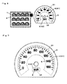
Fig. 1 is a sectional view of an instrument dial according to one embodiment of the invention. -
Fig. 2 is a front view of the instrument dial according to the embodiment. -
Fig. 3 is a front view of a substrate, showing an instrument dial manufacturing method (manufacturing process) according to the embodiment. -
Fig. 4 , showing the instrument dial manufacturing method (manufacturing process) according to the embodiment, is a front view of an underlying portion when it is formed on the substrate. -
Fig. 5 , showing the instrument dial manufacturing method (manufacturing process) according to the embodiment, is a front view of a first background portion when it is formed on the substrate. -
Fig. 6 , showing the instrument dial manufacturing method (manufacturing process) according to the embodiment, is a front view of second background portions when they are formed on the substrate. -
Fig. 7 is a front view of an instrument dial whose variation differs in the embodiment. -
- 1
- Substrate
- 2
- Underlying portion
- 3
- First background portion
- 4
- Second background portions
- 5
- Index portions
- 31
- First non-formation region
- 32
- Second non-formation region
- 41
- First background region
- 42
- Second background region
- Hereafter, a description will be given, using the accompanying drawings, of an embodiment of the invention.
-
Figs. 1 to 7 show one embodiment of an instrument dial and its manufacturing method according to the invention.Figs. 1 and 2 showing a use condition of the instrument dial,Fig. 1 is a sectional view of the instrument dial, andFig. 2 a front view of the instrument dial. Also,Figs. 3 to 6 showing a method (a process) of manufacturing the instrument dial,Fig. 3 is a front view of a substrate,Fig. 4 shows a front view when an underlying portion is formed on the substrate,Fig. 5 shows a front view when a first background portion is formed on the substrate, andFig. 6 shows a front view when second background portions are formed on the substrate. Also,Fig. 7 is a front view of an instrument dial whose basic configuration is the same as that of the instrument dial described inFigs. 1 and 2 , but whose variation differs from that thereof in that index potions have a differing design. - In
Figs. 1 and 2 , the instrument dial according to the embodiment includes asubstrate 1, anunderlying portion 2, afirst background portion 3,second background portions 4, andindex portions 5. InFig. 1 , an instrument mechanism M configured of a pointer, which indicates theindex portions 5, and a drive device, which rotates the pointer in accordance with a measured quantity, is shown by the alternate long and short dash line. - The
substrate 1 is configured of a translucent synthetic resin substrate of, for example, PC (polycarbonate) or PMMA (a methacrylate resign). - The
underlying portion 2 is configured of a print layer obtained by screen (silk) printing, for example, a white translucent ink on thesubstrate 1, in which case theunderlying portion 2 is uniformly printed all over in such a way as to cover the whole region of thesubstrate 1. In the embodiment, theunderlying portion 2 is made of a single colored single layer, but may also be made of multicolored (multilayered). Also, the color and property of theunderlying portion 2 are optional. - The
first background portion 3 is configured of a print layer obtained by screen (silk) printing an ink of a color or brightness differing from that of theunderlying portion 2, for example, a black, opaque ink, on theunderlying portion 2, in which case thefirst background portion 3 does not include design elements (the index portions) such as calibrations, numbers, letters, and marks. Then, thefirst background portion 3, being smaller in formation area than theunderlying portion 2, is formed so as to have a firstnon-formation region 31 through which theunderlying portion 2 is exposed in a shape corresponding to a first background region, to be described hereafter, of thesecond background portions 4, and asecond non-formation region 32 through which theunderlying portion 2 is exposed in a shape corresponding to a second background region, to be described hereafter, of the second background portions 4 (refer toFigs. 1 and5 ). - The
second background portions 4, being configured of a digital print layer formed by using an inkjet method to print, for example, an ultraviolet cure ink on the underlying regions of theunderlying portion 2 positioned in each of the first andsecond non-formation regions first background region 41, which includes theindex portions 5 formed of calibrations and numbers corresponding to vehicle speed values indicated by the pointer, and asecond background region 42 which includes theindex portion 5 configured of letters "km/h" indicating a vehicle speed unit. - Then, in this case, each
index portion 5, as well as having the same color or the same kind of brightness as theunderlying port ion 2, is formed as anindex portion 5 having translucency, and both the first andsecond background regions index portions 5, are formed as opaque backgrounds in black which is the same color as that of thefirst background portion 3. The regions forming the backgrounds may also be printed a plurality of times in order to improve the light blocking effect thereof. Also, thesecond background portions 4 can be set to an optional color, but it is possible to obscure the boundaries between thebackground first background portion 3. - Next, a description will be given, based on
Figs. 3 to 6 . of the instrument dial manufacturing method according to the embodiment. - The
substrate 1 of a predetermined size is prepared. In the embodiment, thesubstrate 1 is used which is of a size such that 12 instrument dials can eventually be made in a series of manufacturing steps. - Next, the
underlying layer 2 is screen printed on a surface of the substrate 1 (a first screen printing step). In this case, theunderlying portion 2 is uniformly printed to cover approximately the whole region of thesubstrate 1. - Next, the
first background portion 3 is printed on a surface of the underlying layer 2 (a second screen printing step). In this case, thefirst background portion 3 is formed in such a way as to form the first and secondnon-formation regions - Next, the second background portions 4 (first and
second background regions 41 and 42) are digitally printed using the inkjet method in such a way as to cover the first and secondnon-formation regions underlying layer 2 is exposed (a digital printing steep). As a digital print technology using the inkjet method itself is described, for example, inJP-A-2006-2149C6 - Next, the
substrate 1 printed as above is cut into individual instrument dial units, thereby completing the instrument dial described inFig. 1 . - The above is the process of manufacturing the instrument dial having the numbers, calibrations, and vehicle speed unit of "km/h" as the
index portions 5. -
Fig. 7 showing an instrument dial having numbers, calibrations, and a vehicle speed unit, which are in "mph", as theindex portions 5, the instrument dial is of the same basic configuration as the instrument dial ofFig. 1 , but differs in variation (for example, destination) therefrom in that the design of theindex portions 5 corresponds to the vehicle speed unit "mph", rather than the vehicle speed unit "km/h". - That is, between the instrument dial of
Fig. 1 and the instrument dial ofFig. 7 , the print design of thesecond background portions 4 configured of a digital print layer only differs according to the vehicle speed unit ("mph", "mph"), and the series of manufacturing (printing) steps, the shape of the screen print layer configured of thesubstrate 1,underlying layer 2, and first background layer 3 (for which a common block is used), and the external shape of the digital print layer, are common. - As heretofore described, in the embodiment, an instrument dial with
index portions 5 provided inbackground portions substrate 1 to printing includes anunderlying portion 2 configured of a screen print layer provided on thesubstrate 1; afirst background portion 3 which, being configured of a screen print layer formed on theunderlying portion 2, does not include theindex portions 5; andsecond background portions 4 which are configured of a digital print layer formed on theunderlying portion 2 and, as well as including theindex portions 5, are continuous with thefirst background portion 3, whereby thefirst background portions 3 andunderlying portion 3 which have no design elements, such as theindex portions 5, can share a block, and thesecond background portions 4 which include a variety of design elements in accordance with a variation development, or the like, can eliminate the need for a block, thereby shortening a print time and simplifying the manufacturing process, meaning that it is possible to achieve a reduction in cost. Theunderlying layer 2 may also be omitted as necessary. - Also, in the embodiment, the
underlying portion 2 is formed on thesubstrate 1 so as to have a wider range than thefirst background portion 3 andsecond background portions 4, thefirst background portion 3 hasnon-formation regions underlying portion 2 is exposed in shapes corresponding to thesecond background portions 4, and thesecond background portions 4 are provided on portions of theunderlying portion 2 positioned in thenon-formation regions second background portions 4 need an underlying layer, meaning that it is possible to achieve a further reduction in cost. - Also, in the embodiment, the digital print layer is configured of an ultraviolet cure ink-jet print layer, thereby enhancing an ink adhesion, and enabling a high definition print, meaning that it is possible to improve merchantability.
- Also, in the embodiment, a method of manufacturing an instrument dial with
index portions 5 provided inbackground portions substrate 1 to printing includes a first screen printing step which forms anunderlying portion 2 on thesubstrate 1; a second screen printing step which forms on the underlying portion 2 afirst background portion 3 which does not include theindex portions 5; and a digital printing step which forms, on theunderlying portion 2,second background portions 4 which, as well as including theindex portions 5, are continuous with thefirst background portion 3, and the instrument dial is manufactured using the steps, whereby thefirst background portion 3 andunderlying portion 3 which have no design elements, such as theindex portions 5, can share a block, and thesecond background portions 4 which include a variety of design elements in accordance with a variation development, or the like, can eliminate the need for a block, thereby shortening the print time and simplifying the manufacturing process, meaning that it is possible to achieve a reduction in cost. The second printing step which forms theunderlying layer 2 may also be omitted as necessary. - Also, in the embodiment, the
underlying portion 2 is formed so as to have a wider range than thefirst background portion 3 andsecond background portions 4, thefirst background portion 3 is formed in such a way as to havenon-formation regions underlying portion 2 is exposed in shapes corresponding to thesecond background portions 4, and thesecond background portions 4 are provided in such a way as to cover portions of theunderlying portion 2 positioned in thenon-formation regions second background portions 4 need an underlying layer, meaning that it is possible to achieve a further reduction in cost. - In the embodiment, a description has been given, as an example, of instrument dials whose
index portion 5 designs differ from one another due to the vehicle speed units, but the invention may be applied in accordance with variations of, for example, a design element relating to a pointer rotation position (range) in a red zone display portion, or the like, and a design element relating to each warning and alarm mark, or the like. - The invention can be applied to an instrument dial mounted not only on a vehicle, but on a vessel, and to a method of manufacturing the instrument dial.
Claims (7)
- An instrument dial with index portions provided in background portions by subjecting a substrate to printing, characterized by including:a first background portion which, being configured of a screen print layer formed on the substrate, does not include the index portions; andsecond background portions which are configured of a digital print layer formed on the substrate and, as well as including the index portions, are continuous with the first background portion.
- An instrument dial with index portions provided in background portions by subjecting a substrate to printing, characterized by including:an underlying portion configured of a screen print layer provided on the substrate;a first background portion which, being configured of a screen print layer formed on the underlying portion, does not include the index portions; andsecond background portions which are configured of a digital print layer formed on the underlying portion and, as well as including the index portions, are continuous with the first background portion.
- The instrument dial according to claim 2, characterized in that
the underlying portion is formed on the substrate so as to have a wider range than the first background portion and second background portions, the first background portion has non-formation regions through which the underlying portion is exposed in shapes corresponding to the second background portions, and the second background portions are provided on portions of the underlying portion positioned in the non-formation regions. - The instrument dial according to claim 1, characterized in that
the digital print layer is configured of an ultraviolet cure ink-jet print layer. - A method of manufacturing an instrument dial with index portions provided in background portions by subjecting a substrate to printing, characterized by including:a screen printing step which forms on the substrate a first background portion which does not includes the index portions; anda digital printing step which forms, on the substrate, second background portions which, as well as including the index portions, are continuous with the first background portion.
- A method of manufacturing an instrument dial with index portions provided in background portions by subjecting a substrate to printing, characterized by including:a first screen printing step which forms an underlying portion on the substrate;a second screen printing step which forms on the underlying portion a first background portion which does not include the index portions; anda digital printing step which forms, on the underlying portion, second background portions which, as well as including the index portions, are continuous with the first background portion.
- The instrument dial manufacturing method according to claim 6, characterized in that
the underlying portion is formed so as to have a wider range than the first background portion and second background portions, and the first background portion is formed in such a way as to have non-formation regions through which the underlying portion is exposed in shapes corresponding to the second background portions, and the second background portions are provided in such a way as to cover the underlying portion positioned in the non-formation regions.
Applications Claiming Priority (2)
| Application Number | Priority Date | Filing Date | Title |
|---|---|---|---|
| JP2008018540A JP5029904B2 (en) | 2008-01-30 | 2008-01-30 | Instrument dial and manufacturing method thereof |
| PCT/JP2008/072800 WO2009096104A1 (en) | 2008-01-30 | 2008-12-16 | Instrument dial and method of manufacturing the same |
Publications (2)
| Publication Number | Publication Date |
|---|---|
| EP2241863A1 true EP2241863A1 (en) | 2010-10-20 |
| EP2241863A4 EP2241863A4 (en) | 2016-07-27 |
Family
ID=40912463
Family Applications (1)
| Application Number | Title | Priority Date | Filing Date |
|---|---|---|---|
| EP08871873.9A Withdrawn EP2241863A4 (en) | 2008-01-30 | 2008-12-16 | INSTRUMENT SCALE AND MANUFACTURING METHOD THEREFOR |
Country Status (6)
| Country | Link |
|---|---|
| US (1) | US8607726B2 (en) |
| EP (1) | EP2241863A4 (en) |
| JP (1) | JP5029904B2 (en) |
| KR (1) | KR101457255B1 (en) |
| CN (1) | CN101932916B (en) |
| WO (1) | WO2009096104A1 (en) |
Cited By (1)
| Publication number | Priority date | Publication date | Assignee | Title |
|---|---|---|---|---|
| DE102015216741A1 (en) | 2015-09-02 | 2017-03-02 | Volkswagen Ag | Process for the pretreatment of a coated material to improve the layer strength |
Families Citing this family (8)
| Publication number | Priority date | Publication date | Assignee | Title |
|---|---|---|---|---|
| JP5834434B2 (en) * | 2011-03-18 | 2015-12-24 | セイコーエプソン株式会社 | Printed matter and method for producing printed matter |
| DE102011016425A1 (en) * | 2011-04-08 | 2012-10-11 | GM Global Technology Operations LLC (n. d. Gesetzen des Staates Delaware) | Instrument for a motor vehicle |
| JP6263842B2 (en) * | 2013-02-22 | 2018-01-24 | 日本精機株式会社 | Display device |
| USD768548S1 (en) * | 2013-07-18 | 2016-10-11 | Volvo Car Corporation | Vehicle instrument with graphical user interface |
| JP6556176B2 (en) * | 2016-03-30 | 2019-08-07 | 矢崎総業株式会社 | Dial and automobile meter |
| DE102017205342B4 (en) | 2016-03-30 | 2020-07-02 | Yazaki Corporation | Dial and motor vehicle measuring instrument |
| EP3502800A1 (en) | 2017-12-20 | 2019-06-26 | ETA SA Manufacture Horlogère Suisse | Method for producing a functional element on a timepiece component |
| KR20210104321A (en) | 2020-02-17 | 2021-08-25 | (주)대신크리에이티브 | Instrument Cluster for Car |
Family Cites Families (17)
| Publication number | Priority date | Publication date | Assignee | Title |
|---|---|---|---|---|
| US293170A (en) * | 1883-09-10 | 1884-02-05 | Geoege e | |
| JPH0655958A (en) * | 1992-08-06 | 1994-03-01 | Mazda Motor Corp | Vehicle display |
| DE19606069C1 (en) * | 1996-02-19 | 1997-08-07 | Wiegand Gmbh & Co Alexander | Method and device for producing a dial |
| JP2002148079A (en) * | 2000-11-10 | 2002-05-22 | Yazaki Corp | Vehicle dial |
| JP4729786B2 (en) * | 2000-11-16 | 2011-07-20 | 株式会社デンソー | Display board for vehicle display device |
| JP2002361833A (en) * | 2001-06-12 | 2002-12-18 | Fuji Photo Film Co Ltd | Hybrid printer |
| US6938551B2 (en) * | 2002-05-06 | 2005-09-06 | Yazaki Corporation | Method of making instrument panel for vehicles |
| DE10226561B4 (en) * | 2002-06-14 | 2006-12-28 | Schott Ag | Glass or glass ceramic article and method of decorating an article of glass or glass ceramic |
| CN2579723Y (en) * | 2002-11-01 | 2003-10-15 | 王诚 | Film coated synthetic color cold light automobile instrument panel |
| US20050196542A1 (en) * | 2003-02-12 | 2005-09-08 | Cooper Johnny G. | Plastic film instrument cluster overlays and method of making |
| JP2004286459A (en) * | 2003-03-19 | 2004-10-14 | Calsonic Kansei Corp | Display panel for automotive instrument and manufacturing method thereof |
| JP2004291336A (en) * | 2003-03-26 | 2004-10-21 | Calsonic Kansei Corp | Decorative items and display panels for automotive instruments |
| JP4501515B2 (en) | 2003-06-16 | 2010-07-14 | 株式会社デンソー | Vehicle display device and display board thereof |
| US20050129879A1 (en) * | 2003-12-12 | 2005-06-16 | Forest Corporation | Base printed with ink receptive medium |
| JP4929655B2 (en) * | 2005-09-14 | 2012-05-09 | 株式会社デンソー | Instrument display board |
| JP5034199B2 (en) * | 2005-09-28 | 2012-09-26 | 株式会社デンソー | Manufacturing method of molded display board |
| JP2008298830A (en) * | 2007-05-29 | 2008-12-11 | Denso Corp | Manufacturing method of display board |
-
2008
- 2008-01-30 JP JP2008018540A patent/JP5029904B2/en not_active Expired - Fee Related
- 2008-12-16 CN CN2008801258403A patent/CN101932916B/en not_active Expired - Fee Related
- 2008-12-16 WO PCT/JP2008/072800 patent/WO2009096104A1/en not_active Ceased
- 2008-12-16 KR KR1020107017832A patent/KR101457255B1/en not_active Expired - Fee Related
- 2008-12-16 US US12/865,638 patent/US8607726B2/en not_active Expired - Fee Related
- 2008-12-16 EP EP08871873.9A patent/EP2241863A4/en not_active Withdrawn
Non-Patent Citations (1)
| Title |
|---|
| See references of WO2009096104A1 * |
Cited By (1)
| Publication number | Priority date | Publication date | Assignee | Title |
|---|---|---|---|---|
| DE102015216741A1 (en) | 2015-09-02 | 2017-03-02 | Volkswagen Ag | Process for the pretreatment of a coated material to improve the layer strength |
Also Published As
| Publication number | Publication date |
|---|---|
| JP2009180572A (en) | 2009-08-13 |
| KR20100111722A (en) | 2010-10-15 |
| EP2241863A4 (en) | 2016-07-27 |
| CN101932916A (en) | 2010-12-29 |
| KR101457255B1 (en) | 2014-10-31 |
| US8607726B2 (en) | 2013-12-17 |
| CN101932916B (en) | 2012-06-13 |
| US20100326348A1 (en) | 2010-12-30 |
| WO2009096104A1 (en) | 2009-08-06 |
| JP5029904B2 (en) | 2012-09-19 |
Similar Documents
| Publication | Publication Date | Title |
|---|---|---|
| US8607726B2 (en) | Instrument dial and its manufacturing method | |
| KR100911566B1 (en) | Car digital integrated information instrument panel | |
| CN1125468C (en) | Instrument panel | |
| JP5418781B2 (en) | Lighting device | |
| US7374323B1 (en) | Self-illumination applique system and method | |
| US6938551B2 (en) | Method of making instrument panel for vehicles | |
| JP2008151699A (en) | Vehicle instrumentation | |
| CN109203994B (en) | vehicle display device | |
| CN108116228B (en) | Panel of automobile instrument panel and preparation method | |
| JP2019086378A (en) | Display device for vehicle and design board | |
| JP2007041404A (en) | Display device | |
| US7108531B2 (en) | Metallic face plate for automotive instrument cluster | |
| KR102147177B1 (en) | Method for manufacturing nameplate color representated onto transparent substrate using laser etching and transparent panel thereof | |
| JP4096909B2 (en) | Vehicle instrument | |
| JP2003240611A (en) | Instrument device | |
| CN108473056A (en) | Holographic moulding | |
| JP2008188831A (en) | Plastic molded product | |
| JP7167773B2 (en) | Display device | |
| CN101334300A (en) | Instrumentation | |
| JP2010243281A (en) | Dial | |
| JP5075406B2 (en) | Instrument device and display method | |
| CN109203993B (en) | vehicle display device | |
| JP3599186B2 (en) | Display device | |
| JPH08201123A (en) | Instrument dial | |
| JP6384159B2 (en) | Display device |
Legal Events
| Date | Code | Title | Description |
|---|---|---|---|
| PUAI | Public reference made under article 153(3) epc to a published international application that has entered the european phase |
Free format text: ORIGINAL CODE: 0009012 |
|
| 17P | Request for examination filed |
Effective date: 20100820 |
|
| AK | Designated contracting states |
Kind code of ref document: A1 Designated state(s): AT BE BG CH CY CZ DE DK EE ES FI FR GB GR HR HU IE IS IT LI LT LU LV MC MT NL NO PL PT RO SE SI SK TR |
|
| AX | Request for extension of the european patent |
Extension state: AL BA MK RS |
|
| DAX | Request for extension of the european patent (deleted) | ||
| RA4 | Supplementary search report drawn up and despatched (corrected) |
Effective date: 20160623 |
|
| RIC1 | Information provided on ipc code assigned before grant |
Ipc: B60K 37/02 20060101ALI20160617BHEP Ipc: G01D 13/04 20060101AFI20160617BHEP |
|
| 17Q | First examination report despatched |
Effective date: 20180920 |
|
| STAA | Information on the status of an ep patent application or granted ep patent |
Free format text: STATUS: THE APPLICATION HAS BEEN WITHDRAWN |
|
| 18W | Application withdrawn |
Effective date: 20181031 |