EP2241739A2 - Controller of a combustion engine for synchronizing the engine during the shutdown - Google Patents
Controller of a combustion engine for synchronizing the engine during the shutdown Download PDFInfo
- Publication number
- EP2241739A2 EP2241739A2 EP10159232A EP10159232A EP2241739A2 EP 2241739 A2 EP2241739 A2 EP 2241739A2 EP 10159232 A EP10159232 A EP 10159232A EP 10159232 A EP10159232 A EP 10159232A EP 2241739 A2 EP2241739 A2 EP 2241739A2
- Authority
- EP
- European Patent Office
- Prior art keywords
- learning
- engine
- loss torque
- learning value
- torque characteristic
- Prior art date
- Legal status (The legal status is an assumption and is not a legal conclusion. Google has not performed a legal analysis and makes no representation as to the accuracy of the status listed.)
- Granted
Links
- 238000002485 combustion reaction Methods 0.000 title description 7
- 230000006399 behavior Effects 0.000 claims abstract description 25
- 238000009499 grossing Methods 0.000 claims description 3
- 238000000034 method Methods 0.000 description 42
- 239000000446 fuel Substances 0.000 description 12
- 230000008569 process Effects 0.000 description 8
- 230000009467 reduction Effects 0.000 description 7
- 230000008859 change Effects 0.000 description 5
- 239000002826 coolant Substances 0.000 description 4
- 239000006185 dispersion Substances 0.000 description 4
- 230000006870 function Effects 0.000 description 4
- 230000006872 improvement Effects 0.000 description 4
- 238000002347 injection Methods 0.000 description 4
- 239000007924 injection Substances 0.000 description 4
- 238000010792 warming Methods 0.000 description 4
- 230000000052 comparative effect Effects 0.000 description 3
- 238000004134 energy conservation Methods 0.000 description 3
- 239000010705 motor oil Substances 0.000 description 3
- 239000003054 catalyst Substances 0.000 description 2
- 238000001514 detection method Methods 0.000 description 2
- 239000000203 mixture Substances 0.000 description 2
- 238000010248 power generation Methods 0.000 description 2
- 238000005086 pumping Methods 0.000 description 2
- 230000002123 temporal effect Effects 0.000 description 2
- 238000012935 Averaging Methods 0.000 description 1
- 238000004364 calculation method Methods 0.000 description 1
- LFHISGNCFUNFFM-UHFFFAOYSA-N chloropicrin Chemical compound [O-][N+](=O)C(Cl)(Cl)Cl LFHISGNCFUNFFM-UHFFFAOYSA-N 0.000 description 1
- 238000010276 construction Methods 0.000 description 1
- 230000003247 decreasing effect Effects 0.000 description 1
- 230000006866 deterioration Effects 0.000 description 1
- 230000005611 electricity Effects 0.000 description 1
- 238000001914 filtration Methods 0.000 description 1
- 238000004519 manufacturing process Methods 0.000 description 1
- 239000003921 oil Substances 0.000 description 1
- 239000007858 starting material Substances 0.000 description 1
- 238000011144 upstream manufacturing Methods 0.000 description 1
Images




Classifications
-
- F—MECHANICAL ENGINEERING; LIGHTING; HEATING; WEAPONS; BLASTING
- F02—COMBUSTION ENGINES; HOT-GAS OR COMBUSTION-PRODUCT ENGINE PLANTS
- F02D—CONTROLLING COMBUSTION ENGINES
- F02D41/00—Electrical control of supply of combustible mixture or its constituents
- F02D41/02—Circuit arrangements for generating control signals
- F02D41/04—Introducing corrections for particular operating conditions
- F02D41/042—Introducing corrections for particular operating conditions for stopping the engine
-
- F—MECHANICAL ENGINEERING; LIGHTING; HEATING; WEAPONS; BLASTING
- F02—COMBUSTION ENGINES; HOT-GAS OR COMBUSTION-PRODUCT ENGINE PLANTS
- F02D—CONTROLLING COMBUSTION ENGINES
- F02D41/00—Electrical control of supply of combustible mixture or its constituents
- F02D41/02—Circuit arrangements for generating control signals
- F02D41/14—Introducing closed-loop corrections
- F02D41/1497—With detection of the mechanical response of the engine
-
- F—MECHANICAL ENGINEERING; LIGHTING; HEATING; WEAPONS; BLASTING
- F02—COMBUSTION ENGINES; HOT-GAS OR COMBUSTION-PRODUCT ENGINE PLANTS
- F02D—CONTROLLING COMBUSTION ENGINES
- F02D41/00—Electrical control of supply of combustible mixture or its constituents
- F02D41/24—Electrical control of supply of combustible mixture or its constituents characterised by the use of digital means
- F02D41/2406—Electrical control of supply of combustible mixture or its constituents characterised by the use of digital means using essentially read only memories
- F02D41/2425—Particular ways of programming the data
- F02D41/2429—Methods of calibrating or learning
- F02D41/2451—Methods of calibrating or learning characterised by what is learned or calibrated
-
- F—MECHANICAL ENGINEERING; LIGHTING; HEATING; WEAPONS; BLASTING
- F02—COMBUSTION ENGINES; HOT-GAS OR COMBUSTION-PRODUCT ENGINE PLANTS
- F02D—CONTROLLING COMBUSTION ENGINES
- F02D41/00—Electrical control of supply of combustible mixture or its constituents
- F02D41/24—Electrical control of supply of combustible mixture or its constituents characterised by the use of digital means
- F02D41/2406—Electrical control of supply of combustible mixture or its constituents characterised by the use of digital means using essentially read only memories
- F02D41/2425—Particular ways of programming the data
- F02D41/2429—Methods of calibrating or learning
- F02D41/2477—Methods of calibrating or learning characterised by the method used for learning
- F02D41/248—Methods of calibrating or learning characterised by the method used for learning using a plurality of learned values
-
- F—MECHANICAL ENGINEERING; LIGHTING; HEATING; WEAPONS; BLASTING
- F02—COMBUSTION ENGINES; HOT-GAS OR COMBUSTION-PRODUCT ENGINE PLANTS
- F02D—CONTROLLING COMBUSTION ENGINES
- F02D41/00—Electrical control of supply of combustible mixture or its constituents
- F02D41/009—Electrical control of supply of combustible mixture or its constituents using means for generating position or synchronisation signals
- F02D2041/0095—Synchronisation of the cylinders during engine shutdown
-
- F—MECHANICAL ENGINEERING; LIGHTING; HEATING; WEAPONS; BLASTING
- F02—COMBUSTION ENGINES; HOT-GAS OR COMBUSTION-PRODUCT ENGINE PLANTS
- F02D—CONTROLLING COMBUSTION ENGINES
- F02D2200/00—Input parameters for engine control
- F02D2200/02—Input parameters for engine control the parameters being related to the engine
- F02D2200/10—Parameters related to the engine output, e.g. engine torque or engine speed
- F02D2200/1006—Engine torque losses, e.g. friction or pumping losses or losses caused by external loads of accessories
-
- F—MECHANICAL ENGINEERING; LIGHTING; HEATING; WEAPONS; BLASTING
- F02—COMBUSTION ENGINES; HOT-GAS OR COMBUSTION-PRODUCT ENGINE PLANTS
- F02N—STARTING OF COMBUSTION ENGINES; STARTING AIDS FOR SUCH ENGINES, NOT OTHERWISE PROVIDED FOR
- F02N19/00—Starting aids for combustion engines, not otherwise provided for
- F02N19/005—Aiding engine start by starting from a predetermined position, e.g. pre-positioning or reverse rotation
-
- F—MECHANICAL ENGINEERING; LIGHTING; HEATING; WEAPONS; BLASTING
- F02—COMBUSTION ENGINES; HOT-GAS OR COMBUSTION-PRODUCT ENGINE PLANTS
- F02N—STARTING OF COMBUSTION ENGINES; STARTING AIDS FOR SUCH ENGINES, NOT OTHERWISE PROVIDED FOR
- F02N19/00—Starting aids for combustion engines, not otherwise provided for
- F02N19/005—Aiding engine start by starting from a predetermined position, e.g. pre-positioning or reverse rotation
- F02N2019/008—Aiding engine start by starting from a predetermined position, e.g. pre-positioning or reverse rotation the engine being stopped in a particular position
Definitions
- the present invention relates to an engine controller having a loss torque learning function for learning a loss torque characteristics of an engine.
- JP-2008-215182A shows an engine controller which controls the engine in such a manner that the engine is stopped at a specified crank angle when an engine stop requirement is generated.
- the engine controller computes a target track by means of a learning value of a loss torque characteristic.
- the target track indicates an engine rotation behavior until the engine stops at a target stop crank angle.
- the engine controller controls a load of a component driven by the engine in such a manner that the actual engine rotation behavior agrees with the target track.
- the engine controller learns a loss torque characteristic of the engine based on at least actual engine rotation behavior.
- a dispersion in the engine rotation behavior can be compensated enough and the engine stop crank angle can be controlled with high accuracy.
- the present invention is made in view of the above matters, and it is an object of the present invention to provide an engine controller which can enhance a learning accuracy with respect to a loss torque characteristic of an engine.
- An engine controller includes a memory means for storing a loss torque characteristic of an engine as a learning value, and a loss torque learning means for updating the learning value based on a loss torque characteristic which is computed based on an actual engine rotation behavior.
- the loss torque learning means includes a first learning means for updating the learning value based on the learning value stored in the memory means and a presently computed loss torque characteristic, a second learning means for updating the learning value based on the presently computed loss torque characteristic without using the learning value stored in the memory means and a switching means for switching between the first learning means and the second learning means in order to update the learning value.
- the first learning means can obtain a reliable learning value without receiving any influence of temporal variation in the loss torque characteristic.
- the second learning means can promptly obtain the learning value according to a present actual loss torque characteristic.
- the first learning means and the second learning means are properly switched to update the learning value.
- the loss torque characteristic learning can be performed in both cases where the learning value is needed to be gradually updated in view of an improvement of the reliability and where the learning value is needed to be updated based on the actual loss torque characteristic in view of an improvement of the convergence.
- the loss torque characteristic learning can be performed suitably.
- an update amount of the learning value by the first learning means is restricted by the learning value stored in the memory, and an update amount of the learning value by the second learning means is not restricted by the stored learning value. Therefore, the learning value by the second learning means is promptly converged to the proper learning value with respect to the actual loss torque characteristic.
- An internal combustion engine is a multi-cylinder gasoline engine.
- An engine control system includes an electronic control unit (ECU) which executes a fuel injection control, an ignition timing control, an idle reduction control and the like.
- ECU electronice control unit
- FIG. 1 shows an entire engine control system.
- An engine 10 is provided with a throttle valve 14 in an intake pipe 11.
- the throttle valve 14 is electrically driven by a throttle actuator 15 such as a DC motor.
- a position of the throttle valve 14 is detected by a throttle position sensor (not shown) provided in the throttle actuator 15.
- a surge tank 16 including an intake air pressure sensor 17 is provided downstream of the throttle valve 14.
- the intake air pressure sensor 17 detects intake air pressure.
- An intake manifold 18 which introduces air into each cylinder of the engine 10 is provided downstream of the surge tank 16, and a fuel injector 19 which injects the fuel is provided at a vicinity of an intake port of the intake manifold 18 of each cylinder.
- An intake valve 21 and an exhaust valve 22 are respectively provided to an intake port and an exhaust port of the engine 10.
- air-fuel mixture is introduced into a combustion chamber 23.
- exhaust valve 22 is opened, exhaust gas is discharged into the exhaust pipe 24.
- a spark plug 27 is disposed for each of the cylinder on a cylinder head of the engine 10.
- the spark plug 27 receives high voltage from an ignition apparatus (not shown) at a specified ignition timing.
- the spark plug 27 generates spark to ignite the air-fuel mixture in the combustion chamber 23.
- a three-way catalyst 31 for purifying CO, HC, NOx and the like in the exhaust gas is provided in the exhaust pipe 24.
- An A/F sensor 32 detecting air-fuel ratio of the exhaust gas is provided in the exhaust pipe 24 upstream of the three-way catalyst 31.
- the engine 10 is provided with a coolant temperature sensor 33 detecting coolant temperature, a crank angle sensor 34 outputting a crank angle signal of rectangular shape for every specified crank angle (for example 30°CA) of a crankshaft, and a cam angle sensor 35 outputting a cam angle signal for every specified cam angle.
- the engine control system includes an accelerator position sensor 36 detecting an accelerator position, a brake sensor 37 detecting a stepped amount of a brake pedal, and a vehicle speed sensor 38 detecting a vehicle speed.
- a rotation of a crankshaft is transmitted to an alternator 39 through a belt.
- the alternator 39 is driven by the engine 10 to generate electrical energy.
- a load of the alternator 39 is controllable by performing duty control of its field current.
- the ECU 40 is comprised of a microcomputer including a CPU, a ROM, a RAM.
- the ECU 40 executes control programs stored in the ROM to perform various controls according to the engine condition. That is, the ECU 40 receives detection signals from various sensors and performs a fuel injection control, an ignition timing control, an idle reduction control and the like.
- the ECU 40 stops the fuel injection and the ignition so that the engine is automatically stopped. Further, when an engine restart condition is satisfied while the engine 10 is stopped, a starter (not shown) cranks the engine 10 and the fuel is injected and ignited to automatically restart the engine 10.
- the engine stop condition includes a condition where the accelerator position sensor 36 indicates the accelerator is not stepped, a condition where the brake sensor 37 indicates the brake pedal is stepped, or a condition where the vehicle speed sensor 38 indicates the vehicle speed is zero.
- the engine restart condition includes a condition where the brake sensor 37 indicates the brake pedal is not stepped.
- the ECU 40 functions as a target track computing means for computing a target track which corresponds to a rotation behavior of the engine until the engine stops at a target stop crank angle. Also, the ECU 40 functions as a stop control means for controlling a load of the alternator 39 in such a manner that the rotation behavior of the engine agrees with the target track. Further, the ECU 40 functions as a loss torque learning means for learning a loss torque characteristic based on an actual rotation behavior of the engine 10.
- the target track is computed based on a target stop crank angle of the engine and a target engine speed at a specified crank angle according to the energy conservation law.
- the target track is computed in a direction to trace back the crank angle.
- the energy conservation law is expressed by a following formula.
- Ne ⁇ i + 1 2 Ne ⁇ i 2 - 2 / J ⁇ Tloss - Tref Ne i
- N e(i+1) represents an engine speed at a time (i+1) of before a specified crank angle (for example, 180°CA) from present time (i)
- Ne (i) represents an engine speed at the present time (i)
- "J" represents an inertia moment of the engine 10
- Tloss represents a loss torque including a pumping loss and a friction loss at a specified crank angle (for example, at TDC).
- the ECU 40 has a backup RAM 41, which is a rewritable nonvolatile memory.
- the loss torque Tloss is stored in the backup RAM 41 as a learning value of a lost torque characteristic.
- Tref ( Ne ( i )) represents a standard load torque of the alternator 39 at the engine speed Ne (i) of the present time (i).
- the target track can be expressed by a map indicating a relationship between a crank angle and a target engine speed, which is computed at a specified crank angle interval (for example, 180°CA).
- the standard load torque Tref ( Ne ( i )) of the alternator 39 is established as the half of the controllable maximum load of the alternator 39, as shown in FIG. 2A .
- the alternator 39 does not output an assist torque unlike a motor generator, the load torque of the alternator 39 can be controlled in positive and negative directions, so that a followability of the engine rotation behavior to the target track can be improved.
- the load torque lower than the standard load torque Tref corresponds to a negative load torque
- the load torque higher than the standard load torque Tref corresponds to a positive load torque.
- the standard load torque Tref ( Ne ( i )) of the alternator 39 may not be limited to the half of maximum load.
- the standard load torque Tref ( Ne ( i )) may be 1/3 , 1/4, 2/3, and 3/4 of the maximum load. That is, the standard load torque Tref ( Ne ( i )) is lower than the maximum load torque of the alternator 39 and is greater than zero. (0 ⁇ Tref ( Ne ( i )) ⁇ Maximum load)
- FIG. 3 A shows a comparative example in which the standard load torque Tref ( Ne ( i )) is set to zero and an engine stop control is performed.
- the load torque of the alternator 39 can be controlled only in a positive direction.
- the standard load torque Tref ( Ne ( i )) is set to a suitable value which is greater than zero and lower than the maximum load torque.
- the load torque of the alternator 39 can be controlled in positive direction and negative direction as shown in FIG. 2B . Even if the actual engine rotation behavior overshoots the target track, the actual engine rotation behavior can be corrected to agree with the target track, as shown in FIG. 3B .
- the target track is computed based on the loss torque Tloss .
- the standard load torque Tref ( Ne ( i )) is computed according to the engine speed Ne (i) and a base load torque is computed so that a difference between a target engine speed and an actual engine speed.
- the standard load torque Tref ( Ne ( i )) is added to the base load torque to obtain a required load torque Talt .
- the required load torque Talt is multiplied by a pulley ratio "Ratio" to be converted into a required shaft torque Tfinal .
- a power generation command is computed according to the required load torque Talt (required shaft torque Tfinal ) and the engine speed Ne (i) of the present time (i).
- the field current of the alternator 39 is controlled based on the power generation command so that the load torque of the alternator 39 is controlled.
- Such a load torque control of the alternator 39 is performed periodically until the actual engine speed falls to a lower limit engine speed Nelow at which the alternator 39 can generate electricity.
- the load torque of the alternator 39 is feedback controlled in such a manner that the actual engine rotation behavior agrees with the target track.
- a loss torque characteristic (loss torque Tloss ) for computing the target track varies due to a manufacturing dispersion and/or a deterioration with age of the engine 10.
- a loss torque characteristic for computing the target track varies due to a manufacturing dispersion and/or a deterioration with age of the engine 10.
- the lost torque characteristic is learned and updated based on the actual engine rotation behavior to be stored in the backup RAM 41.
- the target track is computed based on the updated lost torque characteristic.
- an energy consumed due to the loss torque during a specified crank angle period is computed and the loss torque characteristic is learned based on the consumed energy. That is, when the fuel combustion is terminated according to the engine stop requirement, the engine runs through its inertia and the actual engine speed starts to decrease due to the loss torque (pumping loss and/or friction loss). In this case, the consumed energy due to the loss torque is accurately computed and the loss torque characteristic is accurately learned based on the consumed energy.
- the alternator 39 may be stopped. In this case, since the engine runs through its inertia with the alternator 39 stopped, the consumed energy due to the loss torque can be computed more accurately and the learning accuracy of the lost torque characteristic can be enhanced.
- the loss torque Tloss varies depending on the crank angle of the engine 10 even in a same stroke.
- the loss torque Tloss can be stored in a table for each crank angle.
- the backup RAM can be replaced by an EEPROM.
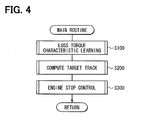
- a main routine of an engine stop learning control shown in FIG. 4 is executed in a specified time interval while the engine is running.
- a loss torque characteristic learning routine shown in FIG. 5 is executed. Only when the learning execution condition is established, the loss torque characteristic is learned.
- a target track computing routine shown in FIG. 6 is executed to compute the target track based on the loss torque characteristic learned in the loss torque characteristic learning routine.
- an engine stop control routine shown in FIG. 7 is executed to control the load torque of the alternator 39 in such a manner that the actual engine rotation behavior agrees with the target track when the engine 10 will be stopped.
- the loss torque characteristic learning routine shown in FIG. 5 is a sub-routine executed in step S100 of the main routine shown in FIG. 4 .
- This loss torque characteristic learning routine corresponds to a loss torque learning means.
- step S101 it is determined whether a learning execution condition is satisfied.
- the learning execution condition includes a condition in which the engine 10 is warmed up and is at idling reduction stage. When at least one of following conditions is satisfied, the computer determines that the engine 10 has been warmed up.
- the learning execution condition may include a condition in which it is a first idle reduction after the warming up of the engine is completed. However, the loss torque characteristic learning can be performed at the second or successive idle reduction.
- the procedure of this routine ends.
- step S101 the procedure proceeds to step S102 in which the computer computes a present crank angle ⁇ and a present engine speed based on detection signals from the crank angle sensor 34 and the cam angle sensor 35.
- step S103 the computer determines whether the present crank angle ⁇ is at top dead center (TDC) which corresponds to a learning value computing timing. When the answer is NO, the procedure of this routine ends. When the answer is YES, the procedure proceeds to step S104 in which the computed engine speed is stored in the RAM as the engine speed Ne (i) at the present TDC.
- TDC top dead center
- step S105 an energy amount ⁇ E consumed due to the loss torque during a period between adjacent TDCs (180°CA) is computed according to the following formula.
- ⁇ E 1 / 2 ⁇ J ⁇ Ne ⁇ i - 1 2 - 1 / 2 ⁇ J ⁇ Ne ⁇ i 2
- J represents an inertia moment of the engine 10
- N e(i-1) represents an engine speed at previous TDC.
- a temporary learning correction torque Tgg and an actual loss torque Tlossg are computed according to the following formulas.
- Tgg ⁇ E - ⁇ Etg
- Tlossg ⁇ E wherein ⁇ Etg represents a consumed energy amount due to the loss torque, which was used for computing previous target track.
- ⁇ Etg is stored in the backup RAM 41.
- the temporary learning correction torque Tgg and the actual loss torque Tlossg can be computed according to the following formulas.
- step S107 the computer determines whether an absolute value of an ratio between the loss torque Tloss used for computing a previous target track and the temporary learning correction torque Tgg is less than or equal to a specified determination value. Specifically, the computer determines whether the absolute value
- the process in step S107 corresponds to a determination means for determining whether a difference between the learning value of the loss torque characteristic stored in the backup RAM 41 and the presently computed loss torque characteristic is greater than or equal to a specified value.
- step S107 the procedure proceeds to step S108 in which the temporary learning correction torque Tgg is smoothed according to the following formula so that a learning correction torque Tg is computed.
- Tg present value a ⁇ Tg previous value + b ⁇ Tgg / a + b wherein "a" and "b" are constant numbers.
- Tg (previous value) is stored in the backup RAM 41.
- step S109 in which the learning correction torque Tg is added to the loss torque Tloss that was used for computing the previous target track, whereby a present loss torque Tloss is obtained.
- the loss torque Tloss stored in the backup RAM 41 is updated.
- step S107 When the answer is NO in step S107, the procedure proceeds to step S110 in which n-counter is incremented by "1". This n-counter is initialized to zero when the learning execution condition is firstly established or when the answer in step S107 is YES. When the answer is successively NO in step S107, the n-counter is continued to be incremented by "1". In step S111, the computer determines whether n-counter is greater than on equal to "3".
- step S111 When the answer is NO in step S111, the procedure proceeds to step S108.
- step S111 the procedure proceeds to step S112.
- the actual loss torque Tlossg computed in step s106 is defined as the present loss torque Tloss , and the loss torque stored in the backup RAM 41 is updated. That is, in step S112, the present loss torque Tloss is computed without using the previous loss torque Tloss and the previous learning correction torque Tg.
- step S109 corresponds to a first learning means
- the process in step S112 corresponds to a second learning means
- the process in step S107 corresponds to a switching means.
- the target track computing routine shown in FIG. 6 is a sub-routine executed in step S200 of the main routine shown in FIG. 4 .
- This target track computing routine corresponds to a target track computing means.
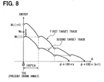
- the target track is established based on the target stop crank angle, the target engine speed at a specified crank angle (TDC) during the engine stop control and the loss torque Tloss (learning value of the loss torque characteristic). Further, when the actual engine speed is brought to coincide with the target engine speed on the target track, two target tracks which deviates 180°CA from each other are established. One of the target tracks is selected, and the target engine speed is computed based on the selected target track. An energy necessary for correcting the actual engine speed to the target engine speed on the selected target track is smaller than that on the other target track.
- the computer computes a present rotation energy at the present engine speed Ne , a first rotation energy at a first target engine speed Nt (i+1) on the first target track, and a second rotation energy at a second target engine speed Nt ( i ) on the second target track.
- An energy difference between the present rotation energy and the first rotation energy and an energy difference between the present rotation energy and the second rotation energy are compared with each other.
- the computer selects one of the target tracks of which the energy difference is smaller than that of the other target track. Based on the selected target track, the target engine speed is computed.
- step S203 the computer determines whether the present engine speed Ne is less than the target engine speed Nt (i+1) which is a square root of the square value of Nt (i+1) computed in step S202.
- the present engine speed Ne is excessive relative to the target engine speed Nt (i+1).
- a higher target engine speed Nt (i+1) is necessary to be computed.
- step S204 in which i-counter is incremented by "1".
- step S202 the target engine speed Nt (i+1) is computed again.
- the target engine speed Nt (i+1) is computed at a crank angle which is traced back by 180°CA.
- step S203 the procedure proceeds to step S205 in which the computer determines whether ( Nt (i+1) - Ne ) is greater than ( Ne - Nt (i)).
- the engine stop control routine shown in FIG. 7 is a sub-routine executed in step S300 of the main routine shown in FIG. 4 .
- This engine stop control routine corresponds to an engine stop control means.
- step S301 the computer determines whether the engine stop requirement (idle reduction signal) is generated. When the answer is NO in step S301, the procedure ends to continue the engine operation. When the answer is YES in step S301, the procedure proceeds to step S302 in which the present crank angle ⁇ and the engine speed Ne are computed.
- step S303 the computer determines whether the present crank angle ⁇ is the control timing (TDC) of the load torque of the alternator 39.
- step S304 the computer determines whether the present engine speed Ne is less than a maximum engine speed Nemax at which the engine stop control can be performed.
- the procedure ends.
- the answers in step S303 and S304 are YES, the procedure proceeds to step S305.
- step S305 the computer determines whether the engine 10 is at a condition of combustion after the engine stop requirement is generated.
- step S307 the required load torque Talt is computed so that the engine speed Ne agrees with the target engine speed Netg according to the energy conservation law and the standard load torque Tref ( Ne ) of the alternator Talt .
- the required load torque Talt is computed based on the following formula.
- Talt J ⁇ K 2 ⁇ ⁇ ⁇ Ne 2 - Netg 2 + Tref Ne
- J represents an inertia moment of the engine 10
- K represents a feedback gain
- ⁇ represents a variation amount in the crank angle (180°CA).
- the target engine speed Netg can be computed according to a map or mathematical equation. Besides, it is also possible to provide the dead band with respect to the deviation in the engine speed.
- step S308 the required load torque Talt is multiplied by a pulley ratio "Ratio", so that the required load torque Talt is converted into the required shaft torque Tfinal of the alternator 39.
- Tfinal Talt ⁇ ⁇ Ratio ⁇
- step S309 the engine speed Ne is multiplied by the pulley ratio "Ratio" to obtain the alternator rotation speed Nalt.
- Nalt Ne ⁇ ⁇ Ratio ⁇
- step S310 a battery voltage is detected.
- an exciting current "IF” is computed based on the required shaft torque Tfinal , an alternator speed Nalt , and the battery voltage. Specifically, a required load torque characteristic map corresponding to the present battery voltage is selected, the exciting current "IF” is computed based on this selected map. The exciting current "IF” is converted into a generating current (duty ratio "Duty”), and the load torque of the alternator 39 is controlled based on the duty ratio "Duty".
- the lost torque characteristic is learned and updated based on the actual engine rotation behavior in order to be stored in the backup RAM 41.
- the dispersion in the loss torque characteristic is compensated by learning and a computation accuracy of the target track can be improved.
- the load torque of the alternator 39 is controlled in such a manner that the actual engine rotation behavior agrees with the target track when the engine 10 will be stopped.
- the dispersion in the actual engine rotation behavior can be compensated and the engine stop position can be controlled within the target crank angle range with high accuracy.
- the first learning means updates the learning value based on the stored learning value ( Tloss ) and the presently computed loss torque characteristic.
- the second learning means updates the learning value based on the presently computed loss torque characteristic.
- the loss torque characteristic learning process it is suitably switched between the first learning means and the second learning means.
- the second learning means updates the learning value based on the presently computed actual loss torque Tlossg without using the loss torque Tloss when a ratio between the loss torque Tloss and the temporal learning correction torque Tgg is greater than a specified determination value.
- the learning value can converge promptly.
- the present invention is not limited to the embodiments described above, but may be performed, for example, in the following manner.
- An ECU (40) includes a backup RAM (41) which stores a learning value of a loss torque characteristic of an engine (10). The learning value is updated based on the loss torque characteristic which is computed based on an actual engine rotation behavior.
- the ECU (40) includes a first learning portion (S109) for updating the learning value based on the learning value stored in the memory and a presently computed loss torque characteristic, and a second learning portion (S112) for updating the learning value based on the presently computed loss torque characteristic without using the learning value stored in the memory.
- a switching portion (S107) switches between the first learning portion and the second learning portion in order to update the learning value.
Landscapes
- Engineering & Computer Science (AREA)
- Chemical & Material Sciences (AREA)
- Combustion & Propulsion (AREA)
- Mechanical Engineering (AREA)
- General Engineering & Computer Science (AREA)
- Combined Controls Of Internal Combustion Engines (AREA)
- Control Of Vehicle Engines Or Engines For Specific Uses (AREA)
Abstract
Description
- The present invention relates to an engine controller having a loss torque learning function for learning a loss torque characteristics of an engine.
-
JP-2008-215182A DE-102008000384A1 ) shows an engine controller which controls the engine in such a manner that the engine is stopped at a specified crank angle when an engine stop requirement is generated. The engine controller computes a target track by means of a learning value of a loss torque characteristic. The target track indicates an engine rotation behavior until the engine stops at a target stop crank angle. Further, the engine controller controls a load of a component driven by the engine in such a manner that the actual engine rotation behavior agrees with the target track. Moreover, the engine controller learns a loss torque characteristic of the engine based on at least actual engine rotation behavior. - A dispersion in the engine rotation behavior can be compensated enough and the engine stop crank angle can be controlled with high accuracy.
- In the above engine controller, it is likely that a loss torque is instantaneously and largely varied due to an instantaneous variation in the friction loss. In order to avoid any influences due to the instantaneous variation in the loss torque, a learning value of the lost torque characteristic is smoothed. However, when an engine friction is largely changed due to an engine oil change and the like, it takes a long time period to converge a learning value to a proper learning value with respect to the actual loss torque.
- The present invention is made in view of the above matters, and it is an object of the present invention to provide an engine controller which can enhance a learning accuracy with respect to a loss torque characteristic of an engine.
- An engine controller includes a memory means for storing a loss torque characteristic of an engine as a learning value, and a loss torque learning means for updating the learning value based on a loss torque characteristic which is computed based on an actual engine rotation behavior.
- According to the present invention, the loss torque learning means includes a first learning means for updating the learning value based on the learning value stored in the memory means and a presently computed loss torque characteristic, a second learning means for updating the learning value based on the presently computed loss torque characteristic without using the learning value stored in the memory means and a switching means for switching between the first learning means and the second learning means in order to update the learning value.
- The first learning means can obtain a reliable learning value without receiving any influence of temporal variation in the loss torque characteristic. The second learning means can promptly obtain the learning value according to a present actual loss torque characteristic. The first learning means and the second learning means are properly switched to update the learning value. Thus, the loss torque characteristic learning can be performed in both cases where the learning value is needed to be gradually updated in view of an improvement of the reliability and where the learning value is needed to be updated based on the actual loss torque characteristic in view of an improvement of the convergence. The loss torque characteristic learning can be performed suitably.
- It should be noted that an update amount of the learning value by the first learning means is restricted by the learning value stored in the memory, and an update amount of the learning value by the second learning means is not restricted by the stored learning value. Therefore, the learning value by the second learning means is promptly converged to the proper learning value with respect to the actual loss torque characteristic.
- Other objects, features and advantages of the present invention will become more apparent from the following description made with reference to the accompanying drawings, in which like parts are designated by like reference numbers and in which:
-
FIG. 1 is a construction view schematically showing an engine control system according to an embodiment of the invention; -
FIG. 2A is a graph for explaining an alternator load characteristic; -
FIG. 2B is a graph for explaining an alternator load characteristic during an engine stop control; -
FIG. 3A is a graph showing a comparative example in which the standard load torque Tref(Ne(i)) =0 and an engine stop control is performed; -
FIG. 3 B is a graph showing an embodiment in which the standard load torque Tref(Ne(i)) is set to half of a maximum load and the engine stop control is performed; -
FIG. 4 is a flowchart showing a main routine of an engine stop learning control; -
FIG. 5 is a flowchart showing a processing of a loss torque characteristic learning routine; -
FIG. 6 is a flowchart showing a processing of a target track computing routine; -
FIG. 7 is a flowchart showing a processing of an engine stop control routine; and -
FIG. 8 is a chart for explaining a calculation method of target engine speed. - Hereinafter, an embodiment that embodies the present invention will be described with reference to the drawings. An internal combustion engine is a multi-cylinder gasoline engine. An engine control system includes an electronic control unit (ECU) which executes a fuel injection control, an ignition timing control, an idle reduction control and the like.
-
FIG. 1 shows an entire engine control system. Anengine 10 is provided with athrottle valve 14 in anintake pipe 11. Thethrottle valve 14 is electrically driven by athrottle actuator 15 such as a DC motor. A position of thethrottle valve 14 is detected by a throttle position sensor (not shown) provided in thethrottle actuator 15. Asurge tank 16 including an intakeair pressure sensor 17 is provided downstream of thethrottle valve 14. The intakeair pressure sensor 17 detects intake air pressure. Anintake manifold 18 which introduces air into each cylinder of theengine 10 is provided downstream of thesurge tank 16, and afuel injector 19 which injects the fuel is provided at a vicinity of an intake port of theintake manifold 18 of each cylinder. - An
intake valve 21 and anexhaust valve 22 are respectively provided to an intake port and an exhaust port of theengine 10. When theintake valve 21 is opened, air-fuel mixture is introduced into acombustion chamber 23. When theexhaust valve 22 is opened, exhaust gas is discharged into theexhaust pipe 24. - A
spark plug 27 is disposed for each of the cylinder on a cylinder head of theengine 10. Thespark plug 27 receives high voltage from an ignition apparatus (not shown) at a specified ignition timing. Thespark plug 27 generates spark to ignite the air-fuel mixture in thecombustion chamber 23. - A three-
way catalyst 31 for purifying CO, HC, NOx and the like in the exhaust gas is provided in theexhaust pipe 24. An A/F sensor 32 detecting air-fuel ratio of the exhaust gas is provided in theexhaust pipe 24 upstream of the three-way catalyst 31. Further, theengine 10 is provided with acoolant temperature sensor 33 detecting coolant temperature, acrank angle sensor 34 outputting a crank angle signal of rectangular shape for every specified crank angle (for example 30°CA) of a crankshaft, and acam angle sensor 35 outputting a cam angle signal for every specified cam angle. The engine control system includes anaccelerator position sensor 36 detecting an accelerator position, abrake sensor 37 detecting a stepped amount of a brake pedal, and avehicle speed sensor 38 detecting a vehicle speed. - A rotation of a crankshaft is transmitted to an
alternator 39 through a belt. Thereby, thealternator 39 is driven by theengine 10 to generate electrical energy. A load of thealternator 39 is controllable by performing duty control of its field current. - The ECU 40 is comprised of a microcomputer including a CPU, a ROM, a RAM. The ECU 40 executes control programs stored in the ROM to perform various controls according to the engine condition. That is, the ECU 40 receives detection signals from various sensors and performs a fuel injection control, an ignition timing control, an idle reduction control and the like.
- When a predetermined engine stop condition is satisfied at idling state, the ECU 40 stops the fuel injection and the ignition so that the engine is automatically stopped. Further, when an engine restart condition is satisfied while the
engine 10 is stopped, a starter (not shown) cranks theengine 10 and the fuel is injected and ignited to automatically restart theengine 10. The engine stop condition includes a condition where theaccelerator position sensor 36 indicates the accelerator is not stepped, a condition where thebrake sensor 37 indicates the brake pedal is stepped, or a condition where thevehicle speed sensor 38 indicates the vehicle speed is zero. The engine restart condition includes a condition where thebrake sensor 37 indicates the brake pedal is not stepped. - Furthermore, the
ECU 40 functions as a target track computing means for computing a target track which corresponds to a rotation behavior of the engine until the engine stops at a target stop crank angle. Also, theECU 40 functions as a stop control means for controlling a load of thealternator 39 in such a manner that the rotation behavior of the engine agrees with the target track. Further, theECU 40 functions as a loss torque learning means for learning a loss torque characteristic based on an actual rotation behavior of theengine 10. - It should be noted that the target track is computed based on a target stop crank angle of the engine and a target engine speed at a specified crank angle according to the energy conservation law. The target track is computed in a direction to trace back the crank angle. The energy conservation law is expressed by a following formula.

wherein Ne(i+1) represents an engine speed at a time (i+1) of before a specified crank angle (for example, 180°CA) from present time (i), Ne(i) represents an engine speed at the present time (i), "J" represents an inertia moment of theengine 10, and Tloss represents a loss torque including a pumping loss and a friction loss at a specified crank angle (for example, at TDC). TheECU 40 has abackup RAM 41, which is a rewritable nonvolatile memory. The loss torque Tloss is stored in thebackup RAM 41 as a learning value of a lost torque characteristic. Tref(Ne(i)) represents a standard load torque of thealternator 39 at the engine speed Ne(i) of the present time (i). - Besides, the target track can be expressed by a map indicating a relationship between a crank angle and a target engine speed, which is computed at a specified crank angle interval (for example, 180°CA).
- In the present embodiment, the standard load torque Tref(Ne(i)) of the
alternator 39 is established as the half of the controllable maximum load of thealternator 39, as shown inFIG. 2A . Although thealternator 39 does not output an assist torque unlike a motor generator, the load torque of thealternator 39 can be controlled in positive and negative directions, so that a followability of the engine rotation behavior to the target track can be improved. It should be noted that the load torque lower than the standard load torque Tref corresponds to a negative load torque, and the load torque higher than the standard load torque Tref corresponds to a positive load torque. - The standard load torque Tref(Ne(i)) of the
alternator 39 may not be limited to the half of maximum load. For example, the standard load torque Tref(Ne(i)) may be 1/3 , 1/4, 2/3, and 3/4 of the maximum load. That is, the standard load torque Tref(Ne(i)) is lower than the maximum load torque of thealternator 39 and is greater than zero. (0< Tref(Ne(i)) < Maximum load) -
FIG. 3 A shows a comparative example in which the standard load torque Tref(Ne(i)) is set to zero and an engine stop control is performed. In this comparative example, the load torque of thealternator 39 can be controlled only in a positive direction. Thus, when the actual engine rotation behavior overshoots the target track, the actual engine rotation behavior can not be corrected to agree with the target track. In the present embodiment, the standard load torque Tref(Ne(i)) is set to a suitable value which is greater than zero and lower than the maximum load torque. Thus, the load torque of thealternator 39 can be controlled in positive direction and negative direction as shown inFIG. 2B . Even if the actual engine rotation behavior overshoots the target track, the actual engine rotation behavior can be corrected to agree with the target track, as shown inFIG. 3B . - Further, in the present embodiment, the target track is computed based on the loss torque Tloss. While the engine stop control is performed, the standard load torque Tref(Ne(i)) is computed according to the engine speed Ne(i) and a base load torque is computed so that a difference between a target engine speed and an actual engine speed. The standard load torque Tref(Ne(i)) is added to the base load torque to obtain a required load torque Talt. Specifically, the required load torque Talt is multiplied by a pulley ratio "Ratio" to be converted into a required shaft torque Tfinal. A power generation command is computed according to the required load torque Talt (required shaft torque Tfinal) and the engine speed Ne(i) of the present time (i). The field current of the
alternator 39 is controlled based on the power generation command so that the load torque of thealternator 39 is controlled. - Such a load torque control of the
alternator 39 is performed periodically until the actual engine speed falls to a lower limit engine speed Nelow at which thealternator 39 can generate electricity. The load torque of thealternator 39 is feedback controlled in such a manner that the actual engine rotation behavior agrees with the target track. - Meanwhile, a loss torque characteristic (loss torque Tloss) for computing the target track varies due to a manufacturing dispersion and/or a deterioration with age of the
engine 10. Thus, if the target track is computed based on a predetermined standard loss torque characteristic and the actual loss torque characteristic deviates from the standard loss torque characteristic, a computation accuracy of the target track is deteriorated. - According to the present embodiment, based on a phenomenon in which a variation in the lost torque characteristic affects the actual engine rotation behavior, the lost torque characteristic is learned and updated based on the actual engine rotation behavior to be stored in the
backup RAM 41. The target track is computed based on the updated lost torque characteristic. - During a period from when a fuel combustion is terminated according to an engine stop requirement (idle reduction signal) until when the engine stop control is started, an energy consumed due to the loss torque during a specified crank angle period is computed and the loss torque characteristic is learned based on the consumed energy. That is, when the fuel combustion is terminated according to the engine stop requirement, the engine runs through its inertia and the actual engine speed starts to decrease due to the loss torque (pumping loss and/or friction loss). In this case, the consumed energy due to the loss torque is accurately computed and the loss torque characteristic is accurately learned based on the consumed energy.
- During a period in which the actual engine speed is decreasing, the
alternator 39 may be stopped. In this case, since the engine runs through its inertia with thealternator 39 stopped, the consumed energy due to the loss torque can be computed more accurately and the learning accuracy of the lost torque characteristic can be enhanced. - It should be noted that the loss torque Tloss varies depending on the crank angle of the
engine 10 even in a same stroke. The loss torque Tloss can be stored in a table for each crank angle. The backup RAM can be replaced by an EEPROM. - The above described learning of the loss torque and the engine stop control are performed by the
ECU 40 according to each routine shown inFIGS. 4 to 7 . The processing of each routine will be described hereinafter. - A main routine of an engine stop learning control shown in
FIG. 4 is executed in a specified time interval while the engine is running. In step S100, a loss torque characteristic learning routine shown inFIG. 5 is executed. Only when the learning execution condition is established, the loss torque characteristic is learned. In step S200, a target track computing routine shown inFIG. 6 is executed to compute the target track based on the loss torque characteristic learned in the loss torque characteristic learning routine. In step S300, an engine stop control routine shown inFIG. 7 is executed to control the load torque of thealternator 39 in such a manner that the actual engine rotation behavior agrees with the target track when theengine 10 will be stopped. - The loss torque characteristic learning routine shown in
FIG. 5 is a sub-routine executed in step S100 of the main routine shown inFIG. 4 . This loss torque characteristic learning routine corresponds to a loss torque learning means. In step S101, it is determined whether a learning execution condition is satisfied. The learning execution condition includes a condition in which theengine 10 is warmed up and is at idling reduction stage. When at least one of following conditions is satisfied, the computer determines that theengine 10 has been warmed up. - When a coolant temperature detected by the
coolant temperature sensor 33 rises to a predetermined value, the computer determines that the warming up of the engine is completed. - When an integrated value of the intake air flow rate after the engine is started (after an ignition switch is turned ON) reaches a predetermined value, the computer determines that the warming up of the engine is completed.
- When an integrated value of the fuel injection quantity after the engine is started (after an ignition switch is turned ON) reaches a predetermined value, the computer determines that the warming up of the engine is completed.
- The learning execution condition may include a condition in which it is a first idle reduction after the warming up of the engine is completed. However, the loss torque characteristic learning can be performed at the second or successive idle reduction. When the answer is NO in step S101, the procedure of this routine ends.
- When the answer is YES in step S101, the procedure proceeds to step S102 in which the computer computes a present crank angle θ and a present engine speed based on detection signals from the
crank angle sensor 34 and thecam angle sensor 35. - In step S103, the computer determines whether the present crank angle θ is at top dead center (TDC) which corresponds to a learning value computing timing. When the answer is NO, the procedure of this routine ends. When the answer is YES, the procedure proceeds to step S104 in which the computed engine speed is stored in the RAM as the engine speed Ne(i) at the present TDC.
- Then, the procedure proceeds to step S105 in which an energy amount ΔE consumed due to the loss torque during a period between adjacent TDCs (180°CA) is computed according to the following formula.

wherein "J" represents an inertia moment of theengine 10, and Ne(i-1) represents an engine speed at previous TDC. - Then, the procedure proceeds to step S106 in which a temporary learning correction torque Tgg and an actual loss torque Tlossg are computed according to the following formulas.


wherein ΔEtg represents a consumed energy amount due to the loss torque, which was used for computing previous target track. ΔEtg is stored in thebackup RAM 41. Alternatively, the temporary learning correction torque Tgg and the actual loss torque Tlossg can be computed according to the following formulas.

wherein Δθ represents a specified crank angle between adjacent TDCs. - Then, the procedure proceeds to step S107 in which the computer determines whether an absolute value of an ratio between the loss torque Tloss used for computing a previous target track and the temporary learning correction torque Tgg is less than or equal to a specified determination value. Specifically, the computer determines whether the absolute value |Tgg / Tloss| is less than or equal to 0.15. The process in step S107 corresponds to a determination means for determining whether a difference between the learning value of the loss torque characteristic stored in the
backup RAM 41 and the presently computed loss torque characteristic is greater than or equal to a specified value. - When the answer is YES in step S107, the procedure proceeds to step S108 in which the temporary learning correction torque Tgg is smoothed according to the following formula so that a learning correction torque Tg is computed.

wherein "a" and "b" are constant numbers. Tg (previous value) is stored in thebackup RAM 41. - Then, the procedure proceeds to step S109 in which the learning correction torque Tg is added to the loss torque Tloss that was used for computing the previous target track, whereby a present loss torque Tloss is obtained. The loss torque Tloss stored in the
backup RAM 41 is updated. - When the answer is NO in step S107, the procedure proceeds to step S110 in which n-counter is incremented by "1". This n-counter is initialized to zero when the learning execution condition is firstly established or when the answer in step S107 is YES. When the answer is successively NO in step S107, the n-counter is continued to be incremented by "1". In step S111, the computer determines whether n-counter is greater than on equal to "3".
- When the answer is NO in step S111, the procedure proceeds to step S108.
- When the answer is YES in step S111, the procedure proceeds to step S112. In step S112, the actual loss torque Tlossg computed in step s106 is defined as the present loss torque Tloss, and the loss torque stored in the
backup RAM 41 is updated. That is, in step S112, the present loss torque Tloss is computed without using the previous loss torque Tloss and the previous learning correction torque Tg. - It should be noted that the process in step S109 corresponds to a first learning means, the process in step S112 corresponds to a second learning means, and the process in step S107 corresponds to a switching means.
- The target track computing routine shown in
FIG. 6 is a sub-routine executed in step S200 of the main routine shown inFIG. 4 . This target track computing routine corresponds to a target track computing means. - An outline of the target track computing routine will be explained first. In the present embodiment, the target track is established based on the target stop crank angle, the target engine speed at a specified crank angle (TDC) during the engine stop control and the loss torque Tloss (learning value of the loss torque characteristic). Further, when the actual engine speed is brought to coincide with the target engine speed on the target track, two target tracks which deviates 180°CA from each other are established. One of the target tracks is selected, and the target engine speed is computed based on the selected target track. An energy necessary for correcting the actual engine speed to the target engine speed on the selected target track is smaller than that on the other target track.
- Specifically, as shown in
FIG. 8 , when two target stop crank angles are established at "ϕ + 180 × k" and "ϕ + 180 × (k+1)", two target tracks are also established corresponding to two target stop crank angles. In each target track, an energy difference at two crank angles which deviate 180°CA from each other corresponds to the loss torque characteristic of theengine 10. The computer computes a present rotation energy at the present engine speed Ne, a first rotation energy at a first target engine speed Nt(i+1) on the first target track, and a second rotation energy at a second target engine speed Nt(i) on the second target track. An energy difference between the present rotation energy and the first rotation energy and an energy difference between the present rotation energy and the second rotation energy are compared with each other. - The computer selects one of the target tracks of which the energy difference is smaller than that of the other target track. Based on the selected target track, the target engine speed is computed.
- Referring back to
FIG. 6 , in step S201, the computer determines whether the present crank angle θ is TDC which is target track computing timing. When the answer is NO, the procedure ends. When the answer is YES, the procedure proceeds to step S202 in which a square value of the first target engine speed Nt(i+1) is computed according to the following formula.
wherein Nt(i) is a target engine speed at the specified TDC during the engine stop control (Ne>0), and Nt(i+1) is a target engine speed at a crank angle which is traced back by 180°CA relative to Nt(i). For example, 200 rpm is established as an initial value of Nt(i). In step S202, the target engine speeds (high target engine speed and low target engine speed) are computed at two crank angles which deviate 180°CA from each other. - Then, the procedure proceeds to step S203 in which the computer determines whether the present engine speed Ne is less than the target engine speed Nt(i+1) which is a square root of the square value of Nt(i+1) computed in step S202. When the answer is NO in step S203, the present engine speed Ne is excessive relative to the target engine speed Nt(i+1). A higher target engine speed Nt(i+1) is necessary to be computed. The procedure proceeds to step S204 in which i-counter is incremented by "1". Then, the procedure goes back to step S202 in which the target engine speed Nt(i+1) is computed again. Thereby, the target engine speed Nt(i+1) is computed at a crank angle which is traced back by 180°CA.
- When the answer is YES in step S203, the procedure proceeds to step S205 in which the computer determines whether (Nt(i+1) - Ne) is greater than (Ne - Nt(i)).
- When the answer is YES in step S205, the procedure proceeds to step S206 in which Nt(i) is employed as the target engine speed. Then, the procedure proceeds to step S207 in which i-counter is decremented from "i" by "1" (i = i - 1). When the answer is NO in step S205, the procedure proceeds to step S208 in which Nt(i+1) is employed as the target engine speed. The procedure proceeds to step S209 in which i-counter is decremented from "i + 1" by "1" (i = (i + 1) - 1).
- The engine stop control routine shown in
FIG. 7 is a sub-routine executed in step S300 of the main routine shown inFIG. 4 . This engine stop control routine corresponds to an engine stop control means. - In step S301, the computer determines whether the engine stop requirement (idle reduction signal) is generated. When the answer is NO in step S301, the procedure ends to continue the engine operation. When the answer is YES in step S301, the procedure proceeds to step S302 in which the present crank angle θ and the engine speed Ne are computed.
- Then, the procedure proceeds to step S303 in which the computer determines whether the present crank angle θ is the control timing (TDC) of the load torque of the
alternator 39. In step S304, the computer determines whether the present engine speed Ne is less than a maximum engine speed Nemax at which the engine stop control can be performed. When any of answers in steps S303 and S304 is NO, the procedure ends. When the answers in step S303 and S304 are YES, the procedure proceeds to step S305. - In step S305, the computer determines whether the
engine 10 is at a condition of combustion after the engine stop requirement is generated. When the answer is YES, the procedure proceeds to step S306 in which the standard load torque Tref(Ne) of thealternator 39, which is computed based on the present engine speed Ne, is defined as the required load torque Talt (Talt = Tref(Ne)). - When the answer is NO in step S305, the procedure proceeds to step S307 in which the required load torque Talt is computed so that the engine speed Ne agrees with the target engine speed Netg according to the energy conservation law and the standard load torque Tref(Ne) of the alternator Talt. Specifically, the required load torque Talt is computed based on the following formula.

wherein, "J" represents an inertia moment of theengine 10, "K" represents a feedback gain, and Δθ represents a variation amount in the crank angle (180°CA). The target engine speed Netg can be computed according to a map or mathematical equation. Besides, it is also possible to provide the dead band with respect to the deviation in the engine speed. - In step S308, the required load torque Talt is multiplied by a pulley ratio "Ratio", so that the required load torque Talt is converted into the required shaft torque Tfinal of the
alternator 39.
- In step S309, the engine speed Ne is multiplied by the pulley ratio "Ratio" to obtain the alternator rotation speed Nalt.

- Then, the procedure proceeds to step S310 in which a battery voltage is detected. In step S311, an exciting current "IF" is computed based on the required shaft torque Tfinal, an alternator speed Nalt, and the battery voltage. Specifically, a required load torque characteristic map corresponding to the present battery voltage is selected, the exciting current "IF" is computed based on this selected map. The exciting current "IF" is converted into a generating current (duty ratio "Duty"), and the load torque of the
alternator 39 is controlled based on the duty ratio "Duty". - According to the present embodiment, following advantages can be obtained.
- In view of a variation in the loss torque characteristic, the lost torque characteristic is learned and updated based on the actual engine rotation behavior in order to be stored in the
backup RAM 41. Thus, the dispersion in the loss torque characteristic is compensated by learning and a computation accuracy of the target track can be improved. Further, the load torque of thealternator 39 is controlled in such a manner that the actual engine rotation behavior agrees with the target track when theengine 10 will be stopped. Thus, the dispersion in the actual engine rotation behavior can be compensated and the engine stop position can be controlled within the target crank angle range with high accuracy. - The first learning means updates the learning value based on the stored learning value (Tloss) and the presently computed loss torque characteristic. The second learning means updates the learning value based on the presently computed loss torque characteristic. In the loss torque characteristic learning process, it is suitably switched between the first learning means and the second learning means. Thus, the loss torque characteristic learning process can be performed in both cases where the learning value is needed to be gradually updated in view of an improvement of the reliability and where the learning value is needed to be updated based on the actual loss torque characteristic in view of an improvement of the convergence.
- Especially, the second learning means updates the learning value based on the presently computed actual loss torque Tlossg without using the loss torque Tloss when a ratio between the loss torque Tloss and the temporal learning correction torque Tgg is greater than a specified determination value. Thus, the learning value can converge promptly.
- The present invention is not limited to the embodiments described above, but may be performed, for example, in the following manner.
- In the loss torque characteristic learning process, the
alternator 39 is stopped to run the engine by its inertia and the various computation with respect to the loss torque Tloss (for example, the computation of the energy consumed amount ΔE, the computation of the learning correction torque Tg, and the like) may be performed with the engine running by its inertia. - In the loss torque characteristic learning process, the second learning means can updates the learning value by an average value of a plurality of computation values of the loss torque characteristic. Specifically, in step S112 of the loss torque characteristic learning routine shown in
FIG. 5 , an average value of the actual loss torque Tlossgn , Tlossgn-1, Tlossgn-2 is computed and this average value is stored in thebackup RAM 41 as a new loss torque Tloss.
- According to the above-mentioned configuration, even if a difference between the stored learning value and the presently learning value is greater than a specified value, the learning accuracy of the loss torque characteristic can be ensured.
- When the computer determines that a factor of friction loss is changed, the second learning means can update the learning value in stead of the first learning means. For example, when engine oil is changed or a piston ring is changed, the computer determines which is a factor of friction loss based on their history information. Specifically, in step S107 of the loss torque characteristic learning routine shown in
FIG. 5 , the computer confirms the history information of the oil change or the piston ring change. When there is a history information indicating the engine oil or the piston ring is changed, the update of the learning value is performed by the second learning means (step S112). - When the computer determines that the learning value stored in the
backup RAM 41 has evaporated or the learning value is still the initial value, the update of the learning value can be performed by the second learning means instead of the first learning means. For example, the computer determines that the learning value has evaporated when a battery is changed or a battery terminal is detached. Specifically, in step S107 of the loss torque characteristic learning routine shown inFIG. 5 , the computer confirms the history information of the battery change or the battery terminal detaching. When there is a history information indicating the battery change or the detaching of the battery terminal, the update of the learning value is performed by the second learning means (step S112). - A first order lag procedure, an averaging procedure or a filtering procedure can be employed as the smoothing procedure of the learning value (Tloss) of the loss torque characteristic.
- The present invention can be applied to a system in which a load of compressor of air conditioner is controlled.
- An ECU (40) includes a backup RAM (41) which stores a learning value of a loss torque characteristic of an engine (10). The learning value is updated based on the loss torque characteristic which is computed based on an actual engine rotation behavior. The ECU (40) includes a first learning portion (S109) for updating the learning value based on the learning value stored in the memory and a presently computed loss torque characteristic, and a second learning portion (S112) for updating the learning value based on the presently computed loss torque characteristic without using the learning value stored in the memory. A switching portion (S107) switches between the first learning portion and the second learning portion in order to update the learning value.
Claims (7)
- An engine controller comprising:a memory means (41) for storing a loss torque characteristic of an engine as a learning value; anda loss torque learning means (40, S100) for updating the learning value based on a loss torque characteristic which is computed based on an actual engine rotation behavior, whereinthe loss torque learning means includes;a first learning means (S109) for updating the learning value based on the learning value stored in the memory means and a presently computed loss torque characteristic;a second learning means (S112) for updating the learning value based on the presently computed loss torque characteristic without using the learning value stored in the memory means; anda switching means (S107) for switching between the first learning means and the second learning means in order to update the learning value.
- An engine controller according to claim 1, further comprising:a determination means (S107) for determining whether a difference between the learning value stored in the memory means and a presently computed loss torque characteristic is greater than or equal to a specified value, whereinwhen said difference is greater than or equal to the specified value, the second learning means updates the learning value.
- An engine controller according to claim 2, further comprising:a learning execution determination means for determining whether a learning execution condition is established for learning the loss torque characteristic, whereinwhen the determination means determines that said difference is greater than or equal to the specified value more than specified times while the learning execution condition is established, the second learning means updates the learning value.
- An engine controller according to any one of claims 1 to 3, further comprising:a variation determination means (40) for determining whether a factor causing a friction loss of the engine is varied, whereinwhen the variation determination means determines that the factor causing the friction loss of the engine is varied, the second learning means updates the learning value.
- An engine controller according to any one of claims 1 to 4, further comprising:a learning condition determination means (40) for determining whether the learning value stored in the memory means has evaporated or whether the learning value stored in the memory means is an initial value, whereinwhen the learning condition determination means determines that the learning value stored in the memory means has evaporated or the learning value stored in the memory means is the initial value, the second learning means updates the learning value.
- An engine controller according to any one of claims 1 to 5, wherein
the first learning means updates the learning value stored in the memory means by smoothing the presently computed loss torque characteristic, and
the second learning means updates the learning value stored in the memory means based on the presently computed loss torque characteristic without smoothing. - An engine controller according to any one of claims 1 to 6, further comprising:a target track computing means (S200-S209) for computing a target track by using of the learning value of the loss torque characteristic stored in the memory means, the target track indicating an engine rotation behavior until the engine stops at a target stop crank angle, andan engine stop control means (S300-S311) for performing an engine stop control in which a load of a component driven by the engine is controlled in such a manner that an actual engine rotation behavior agrees with the target track.
Applications Claiming Priority (1)
| Application Number | Priority Date | Filing Date | Title |
|---|---|---|---|
| JP2009092759A JP5461049B2 (en) | 2009-04-07 | 2009-04-07 | Engine control device |
Publications (3)
| Publication Number | Publication Date |
|---|---|
| EP2241739A2 true EP2241739A2 (en) | 2010-10-20 |
| EP2241739A3 EP2241739A3 (en) | 2018-07-04 |
| EP2241739B1 EP2241739B1 (en) | 2019-12-25 |
Family
ID=42359549
Family Applications (1)
| Application Number | Title | Priority Date | Filing Date |
|---|---|---|---|
| EP10159232.7A Active EP2241739B1 (en) | 2009-04-07 | 2010-04-07 | Controller of an internal combustion engine for synchronizing the engine during the engine shutdown |
Country Status (2)
| Country | Link |
|---|---|
| EP (1) | EP2241739B1 (en) |
| JP (1) | JP5461049B2 (en) |
Cited By (4)
| Publication number | Priority date | Publication date | Assignee | Title |
|---|---|---|---|---|
| CN103184944A (en) * | 2011-12-29 | 2013-07-03 | 罗伯特·博世有限公司 | Method for operating petrol engine, |
| CN103511102A (en) * | 2012-06-14 | 2014-01-15 | 罗伯特·博世有限公司 | Method and apparatus for adapting the torque of an internal combustion engine |
| CN108227482A (en) * | 2016-12-14 | 2018-06-29 | 发那科株式会社 | Control system and machine learning device |
| CN113217205A (en) * | 2020-02-05 | 2021-08-06 | 丰田自动车株式会社 | Control device and control method for internal combustion engine |
Families Citing this family (1)
| Publication number | Priority date | Publication date | Assignee | Title |
|---|---|---|---|---|
| JP6308126B2 (en) * | 2014-12-26 | 2018-04-11 | トヨタ自動車株式会社 | Engine stop device |
Citations (1)
| Publication number | Priority date | Publication date | Assignee | Title |
|---|---|---|---|---|
| JP2008215182A (en) | 2007-03-05 | 2008-09-18 | Denso Corp | Engine rotation stop control device |
Family Cites Families (9)
| Publication number | Priority date | Publication date | Assignee | Title |
|---|---|---|---|---|
| JPH09112310A (en) * | 1995-10-13 | 1997-04-28 | Nissan Motor Co Ltd | Air-fuel ratio control device for internal combustion engine |
| GB2329713A (en) * | 1997-09-30 | 1999-03-31 | Ford Global Tech Inc | IC engine net torque calculator |
| DE10043689A1 (en) * | 2000-09-04 | 2002-03-14 | Bosch Gmbh Robert | Loss moment adaptation method for combustion engine of vehicle involves adjusting loss moment adaptation depending on operation modes whose moments are dependent on air volume or fuel |
| JP4016633B2 (en) * | 2001-10-19 | 2007-12-05 | 日産自動車株式会社 | Fuel injection control device for internal combustion engine |
| US7054738B1 (en) * | 2005-10-17 | 2006-05-30 | Ford Global Technologies, Llc | Method for estimating engine friction torque |
| DE102006005701B4 (en) * | 2006-02-08 | 2020-10-01 | Robert Bosch Gmbh | Method and device for operating a drive unit, computer program product and computer program |
| JP4631775B2 (en) * | 2006-03-29 | 2011-02-16 | トヨタ自動車株式会社 | Stop position control device for internal combustion engine |
| JP2008215320A (en) * | 2007-03-07 | 2008-09-18 | Denso Corp | Torque control device |
| JP4803457B2 (en) * | 2007-09-18 | 2011-10-26 | 株式会社デンソー | Throttle control device for internal combustion engine |
-
2009
- 2009-04-07 JP JP2009092759A patent/JP5461049B2/en not_active Expired - Fee Related
-
2010
- 2010-04-07 EP EP10159232.7A patent/EP2241739B1/en active Active
Patent Citations (2)
| Publication number | Priority date | Publication date | Assignee | Title |
|---|---|---|---|---|
| JP2008215182A (en) | 2007-03-05 | 2008-09-18 | Denso Corp | Engine rotation stop control device |
| DE102008000384A1 (en) | 2007-03-05 | 2008-09-25 | Denso Corp., Kariya | Engine stop control unit |
Cited By (7)
| Publication number | Priority date | Publication date | Assignee | Title |
|---|---|---|---|---|
| CN103184944A (en) * | 2011-12-29 | 2013-07-03 | 罗伯特·博世有限公司 | Method for operating petrol engine, |
| DE102011090095A1 (en) * | 2011-12-29 | 2013-07-04 | Robert Bosch Gmbh | Method for operating e.g. petrol engine, of motor vehicle, involves controlling pump of combustion engine such that fuel discharge of engine is controlled so that engine reaches position in which restart of engine is simplified |
| DE102011090095B4 (en) * | 2011-12-29 | 2015-04-09 | Robert Bosch Gmbh | Method for operating an internal combustion engine |
| CN103511102A (en) * | 2012-06-14 | 2014-01-15 | 罗伯特·博世有限公司 | Method and apparatus for adapting the torque of an internal combustion engine |
| CN108227482A (en) * | 2016-12-14 | 2018-06-29 | 发那科株式会社 | Control system and machine learning device |
| CN113217205A (en) * | 2020-02-05 | 2021-08-06 | 丰田自动车株式会社 | Control device and control method for internal combustion engine |
| CN113217205B (en) * | 2020-02-05 | 2023-01-03 | 丰田自动车株式会社 | Control device and control method for internal combustion engine |
Also Published As
| Publication number | Publication date |
|---|---|
| EP2241739B1 (en) | 2019-12-25 |
| JP2010242633A (en) | 2010-10-28 |
| EP2241739A3 (en) | 2018-07-04 |
| JP5461049B2 (en) | 2014-04-02 |
Similar Documents
| Publication | Publication Date | Title |
|---|---|---|
| US8676478B2 (en) | Engine stop control device | |
| US7848875B2 (en) | Engine automatic stop-start controller | |
| US8000885B2 (en) | Engine stop control device | |
| CN101265846A (en) | engine control unit | |
| JP4666286B2 (en) | Engine rotation stop control device | |
| JP5113611B2 (en) | Control device after starting diesel engine | |
| EP2241739B1 (en) | Controller of an internal combustion engine for synchronizing the engine during the engine shutdown | |
| JP3654010B2 (en) | Control device for internal combustion engine | |
| US9273624B2 (en) | Control system having idle speed control learning and method having idle speed control learning for internal combustion engine | |
| JP4811741B2 (en) | Engine rotation stop control device | |
| CN100520025C (en) | Internal combustion engine stop and start method, vehicle and system comprising internal combustion engines | |
| JP5273547B2 (en) | Engine control device | |
| JP5731735B2 (en) | Engine control device | |
| JPH08200166A (en) | Air-fuel ratio control device | |
| JP4661747B2 (en) | Engine stop control device | |
| JP3478170B2 (en) | Idle speed control device for internal combustion engine | |
| JP5374471B2 (en) | Engine rotation stop control device | |
| JP5610979B2 (en) | Control device for internal combustion engine | |
| JP2000257490A (en) | Intake air amount control device for internal combustion engine | |
| KR100291975B1 (en) | Cylinder injection fuel control device of internal combustion engine | |
| JP2010007523A (en) | Air-fuel ratio control device for engine | |
| WO2024201975A1 (en) | Internal combustion engine control device and control system for mobile object | |
| JP2002038993A (en) | Control device for in-cylinder injection engine | |
| JP2012082735A (en) | Engine revolution stop control device | |
| JP3591046B2 (en) | Fuel injection amount control device for internal combustion engine |
Legal Events
| Date | Code | Title | Description |
|---|---|---|---|
| PUAI | Public reference made under article 153(3) epc to a published international application that has entered the european phase |
Free format text: ORIGINAL CODE: 0009012 |
|
| AK | Designated contracting states |
Kind code of ref document: A2 Designated state(s): AT BE BG CH CY CZ DE DK EE ES FI FR GB GR HR HU IE IS IT LI LT LU LV MC MK MT NL NO PL PT RO SE SI SK SM TR |
|
| AX | Request for extension of the european patent |
Extension state: AL BA ME RS |
|
| RAP1 | Party data changed (applicant data changed or rights of an application transferred) |
Owner name: TOYOTA JIDOSHA KABUSHIKI KAISHA Owner name: DENSO CORPORATION |
|
| PUAL | Search report despatched |
Free format text: ORIGINAL CODE: 0009013 |
|
| RAP1 | Party data changed (applicant data changed or rights of an application transferred) |
Owner name: DENSO CORPORATION |
|
| STAA | Information on the status of an ep patent application or granted ep patent |
Free format text: STATUS: REQUEST FOR EXAMINATION WAS MADE |
|
| AK | Designated contracting states |
Kind code of ref document: A3 Designated state(s): AT BE BG CH CY CZ DE DK EE ES FI FR GB GR HR HU IE IS IT LI LT LU LV MC MK MT NL NO PL PT RO SE SI SK SM TR |
|
| AX | Request for extension of the european patent |
Extension state: AL BA ME RS |
|
| RIC1 | Information provided on ipc code assigned before grant |
Ipc: F02D 41/24 20060101ALI20180528BHEP Ipc: F02D 41/00 20060101ALN20180528BHEP Ipc: F02D 41/04 20060101AFI20180528BHEP Ipc: F02D 41/14 20060101ALI20180528BHEP Ipc: F02N 19/00 20100101ALN20180528BHEP |
|
| 17P | Request for examination filed |
Effective date: 20180621 |
|
| RBV | Designated contracting states (corrected) |
Designated state(s): AT BE BG CH CY CZ DE DK EE ES FI FR GB GR HR HU IE IS IT LI LT LU LV MC MK MT NL NO PL PT RO SE SI SK SM TR |
|
| REG | Reference to a national code |
Ref country code: DE Ref legal event code: R079 Ref document number: 602010062488 Country of ref document: DE Free format text: PREVIOUS MAIN CLASS: F02D0041240000 Ipc: F02D0041040000 |
|
| RIC1 | Information provided on ipc code assigned before grant |
Ipc: F02D 41/00 20060101ALN20190524BHEP Ipc: F02D 41/14 20060101ALI20190524BHEP Ipc: F02N 19/00 20100101ALN20190524BHEP Ipc: F02D 41/24 20060101ALI20190524BHEP Ipc: F02D 41/04 20060101AFI20190524BHEP |
|
| GRAP | Despatch of communication of intention to grant a patent |
Free format text: ORIGINAL CODE: EPIDOSNIGR1 |
|
| STAA | Information on the status of an ep patent application or granted ep patent |
Free format text: STATUS: GRANT OF PATENT IS INTENDED |
|
| INTG | Intention to grant announced |
Effective date: 20190710 |
|
| RIN1 | Information on inventor provided before grant (corrected) |
Inventor name: UTSUNOMIYA, YAMATO Inventor name: OKAMURA, KOJI Inventor name: KAWAHARA, KENJI Inventor name: YOSHIHARA, MASATOMO Inventor name: SHIBATA, MISAO |
|
| GRAS | Grant fee paid |
Free format text: ORIGINAL CODE: EPIDOSNIGR3 |
|
| GRAA | (expected) grant |
Free format text: ORIGINAL CODE: 0009210 |
|
| STAA | Information on the status of an ep patent application or granted ep patent |
Free format text: STATUS: THE PATENT HAS BEEN GRANTED |
|
| AK | Designated contracting states |
Kind code of ref document: B1 Designated state(s): AT BE BG CH CY CZ DE DK EE ES FI FR GB GR HR HU IE IS IT LI LT LU LV MC MK MT NL NO PL PT RO SE SI SK SM TR |
|
| REG | Reference to a national code |
Ref country code: GB Ref legal event code: FG4D |
|
| REG | Reference to a national code |
Ref country code: CH Ref legal event code: EP |
|
| REG | Reference to a national code |
Ref country code: DE Ref legal event code: R096 Ref document number: 602010062488 Country of ref document: DE |
|
| REG | Reference to a national code |
Ref country code: AT Ref legal event code: REF Ref document number: 1217389 Country of ref document: AT Kind code of ref document: T Effective date: 20200115 |
|
| REG | Reference to a national code |
Ref country code: IE Ref legal event code: FG4D |
|
| REG | Reference to a national code |
Ref country code: NL Ref legal event code: MP Effective date: 20191225 |
|
| PG25 | Lapsed in a contracting state [announced via postgrant information from national office to epo] |
Ref country code: SE Free format text: LAPSE BECAUSE OF FAILURE TO SUBMIT A TRANSLATION OF THE DESCRIPTION OR TO PAY THE FEE WITHIN THE PRESCRIBED TIME-LIMIT Effective date: 20191225 Ref country code: LV Free format text: LAPSE BECAUSE OF FAILURE TO SUBMIT A TRANSLATION OF THE DESCRIPTION OR TO PAY THE FEE WITHIN THE PRESCRIBED TIME-LIMIT Effective date: 20191225 Ref country code: LT Free format text: LAPSE BECAUSE OF FAILURE TO SUBMIT A TRANSLATION OF THE DESCRIPTION OR TO PAY THE FEE WITHIN THE PRESCRIBED TIME-LIMIT Effective date: 20191225 Ref country code: NO Free format text: LAPSE BECAUSE OF FAILURE TO SUBMIT A TRANSLATION OF THE DESCRIPTION OR TO PAY THE FEE WITHIN THE PRESCRIBED TIME-LIMIT Effective date: 20200325 Ref country code: GR Free format text: LAPSE BECAUSE OF FAILURE TO SUBMIT A TRANSLATION OF THE DESCRIPTION OR TO PAY THE FEE WITHIN THE PRESCRIBED TIME-LIMIT Effective date: 20200326 Ref country code: FI Free format text: LAPSE BECAUSE OF FAILURE TO SUBMIT A TRANSLATION OF THE DESCRIPTION OR TO PAY THE FEE WITHIN THE PRESCRIBED TIME-LIMIT Effective date: 20191225 Ref country code: BG Free format text: LAPSE BECAUSE OF FAILURE TO SUBMIT A TRANSLATION OF THE DESCRIPTION OR TO PAY THE FEE WITHIN THE PRESCRIBED TIME-LIMIT Effective date: 20200325 |
|
| REG | Reference to a national code |
Ref country code: LT Ref legal event code: MG4D |
|
| PG25 | Lapsed in a contracting state [announced via postgrant information from national office to epo] |
Ref country code: HR Free format text: LAPSE BECAUSE OF FAILURE TO SUBMIT A TRANSLATION OF THE DESCRIPTION OR TO PAY THE FEE WITHIN THE PRESCRIBED TIME-LIMIT Effective date: 20191225 |
|
| PG25 | Lapsed in a contracting state [announced via postgrant information from national office to epo] |
Ref country code: RO Free format text: LAPSE BECAUSE OF FAILURE TO SUBMIT A TRANSLATION OF THE DESCRIPTION OR TO PAY THE FEE WITHIN THE PRESCRIBED TIME-LIMIT Effective date: 20191225 Ref country code: EE Free format text: LAPSE BECAUSE OF FAILURE TO SUBMIT A TRANSLATION OF THE DESCRIPTION OR TO PAY THE FEE WITHIN THE PRESCRIBED TIME-LIMIT Effective date: 20191225 Ref country code: PT Free format text: LAPSE BECAUSE OF FAILURE TO SUBMIT A TRANSLATION OF THE DESCRIPTION OR TO PAY THE FEE WITHIN THE PRESCRIBED TIME-LIMIT Effective date: 20200520 Ref country code: NL Free format text: LAPSE BECAUSE OF FAILURE TO SUBMIT A TRANSLATION OF THE DESCRIPTION OR TO PAY THE FEE WITHIN THE PRESCRIBED TIME-LIMIT Effective date: 20191225 Ref country code: CZ Free format text: LAPSE BECAUSE OF FAILURE TO SUBMIT A TRANSLATION OF THE DESCRIPTION OR TO PAY THE FEE WITHIN THE PRESCRIBED TIME-LIMIT Effective date: 20191225 |
|
| PG25 | Lapsed in a contracting state [announced via postgrant information from national office to epo] |
Ref country code: SM Free format text: LAPSE BECAUSE OF FAILURE TO SUBMIT A TRANSLATION OF THE DESCRIPTION OR TO PAY THE FEE WITHIN THE PRESCRIBED TIME-LIMIT Effective date: 20191225 Ref country code: IS Free format text: LAPSE BECAUSE OF FAILURE TO SUBMIT A TRANSLATION OF THE DESCRIPTION OR TO PAY THE FEE WITHIN THE PRESCRIBED TIME-LIMIT Effective date: 20200425 Ref country code: SK Free format text: LAPSE BECAUSE OF FAILURE TO SUBMIT A TRANSLATION OF THE DESCRIPTION OR TO PAY THE FEE WITHIN THE PRESCRIBED TIME-LIMIT Effective date: 20191225 |
|
| REG | Reference to a national code |
Ref country code: DE Ref legal event code: R097 Ref document number: 602010062488 Country of ref document: DE |
|
| PG25 | Lapsed in a contracting state [announced via postgrant information from national office to epo] |
Ref country code: ES Free format text: LAPSE BECAUSE OF FAILURE TO SUBMIT A TRANSLATION OF THE DESCRIPTION OR TO PAY THE FEE WITHIN THE PRESCRIBED TIME-LIMIT Effective date: 20191225 Ref country code: DK Free format text: LAPSE BECAUSE OF FAILURE TO SUBMIT A TRANSLATION OF THE DESCRIPTION OR TO PAY THE FEE WITHIN THE PRESCRIBED TIME-LIMIT Effective date: 20191225 |
|
| PLBE | No opposition filed within time limit |
Free format text: ORIGINAL CODE: 0009261 |
|
| STAA | Information on the status of an ep patent application or granted ep patent |
Free format text: STATUS: NO OPPOSITION FILED WITHIN TIME LIMIT |
|
| REG | Reference to a national code |
Ref country code: AT Ref legal event code: MK05 Ref document number: 1217389 Country of ref document: AT Kind code of ref document: T Effective date: 20191225 |
|
| PG25 | Lapsed in a contracting state [announced via postgrant information from national office to epo] |
Ref country code: SI Free format text: LAPSE BECAUSE OF FAILURE TO SUBMIT A TRANSLATION OF THE DESCRIPTION OR TO PAY THE FEE WITHIN THE PRESCRIBED TIME-LIMIT Effective date: 20191225 Ref country code: MC Free format text: LAPSE BECAUSE OF FAILURE TO SUBMIT A TRANSLATION OF THE DESCRIPTION OR TO PAY THE FEE WITHIN THE PRESCRIBED TIME-LIMIT Effective date: 20191225 |
|
| REG | Reference to a national code |
Ref country code: CH Ref legal event code: PL |
|
| 26N | No opposition filed |
Effective date: 20200928 |
|
| PG25 | Lapsed in a contracting state [announced via postgrant information from national office to epo] |
Ref country code: LI Free format text: LAPSE BECAUSE OF NON-PAYMENT OF DUE FEES Effective date: 20200430 Ref country code: IT Free format text: LAPSE BECAUSE OF FAILURE TO SUBMIT A TRANSLATION OF THE DESCRIPTION OR TO PAY THE FEE WITHIN THE PRESCRIBED TIME-LIMIT Effective date: 20191225 Ref country code: CH Free format text: LAPSE BECAUSE OF NON-PAYMENT OF DUE FEES Effective date: 20200430 Ref country code: LU Free format text: LAPSE BECAUSE OF NON-PAYMENT OF DUE FEES Effective date: 20200407 Ref country code: AT Free format text: LAPSE BECAUSE OF FAILURE TO SUBMIT A TRANSLATION OF THE DESCRIPTION OR TO PAY THE FEE WITHIN THE PRESCRIBED TIME-LIMIT Effective date: 20191225 |
|
| REG | Reference to a national code |
Ref country code: BE Ref legal event code: MM Effective date: 20200430 |
|
| PG25 | Lapsed in a contracting state [announced via postgrant information from national office to epo] |
Ref country code: BE Free format text: LAPSE BECAUSE OF NON-PAYMENT OF DUE FEES Effective date: 20200430 Ref country code: PL Free format text: LAPSE BECAUSE OF FAILURE TO SUBMIT A TRANSLATION OF THE DESCRIPTION OR TO PAY THE FEE WITHIN THE PRESCRIBED TIME-LIMIT Effective date: 20191225 |
|
| PG25 | Lapsed in a contracting state [announced via postgrant information from national office to epo] |
Ref country code: IE Free format text: LAPSE BECAUSE OF NON-PAYMENT OF DUE FEES Effective date: 20200407 |
|
| PG25 | Lapsed in a contracting state [announced via postgrant information from national office to epo] |
Ref country code: TR Free format text: LAPSE BECAUSE OF FAILURE TO SUBMIT A TRANSLATION OF THE DESCRIPTION OR TO PAY THE FEE WITHIN THE PRESCRIBED TIME-LIMIT Effective date: 20191225 Ref country code: MT Free format text: LAPSE BECAUSE OF FAILURE TO SUBMIT A TRANSLATION OF THE DESCRIPTION OR TO PAY THE FEE WITHIN THE PRESCRIBED TIME-LIMIT Effective date: 20191225 Ref country code: CY Free format text: LAPSE BECAUSE OF FAILURE TO SUBMIT A TRANSLATION OF THE DESCRIPTION OR TO PAY THE FEE WITHIN THE PRESCRIBED TIME-LIMIT Effective date: 20191225 |
|
| PG25 | Lapsed in a contracting state [announced via postgrant information from national office to epo] |
Ref country code: MK Free format text: LAPSE BECAUSE OF FAILURE TO SUBMIT A TRANSLATION OF THE DESCRIPTION OR TO PAY THE FEE WITHIN THE PRESCRIBED TIME-LIMIT Effective date: 20191225 |
|
| PGFP | Annual fee paid to national office [announced via postgrant information from national office to epo] |
Ref country code: GB Payment date: 20220425 Year of fee payment: 13 Ref country code: FR Payment date: 20220421 Year of fee payment: 13 Ref country code: DE Payment date: 20220420 Year of fee payment: 13 |
|
| REG | Reference to a national code |
Ref country code: DE Ref legal event code: R119 Ref document number: 602010062488 Country of ref document: DE |
|
| GBPC | Gb: european patent ceased through non-payment of renewal fee |
Effective date: 20230407 |
|
| PG25 | Lapsed in a contracting state [announced via postgrant information from national office to epo] |
Ref country code: GB Free format text: LAPSE BECAUSE OF NON-PAYMENT OF DUE FEES Effective date: 20230407 |
|
| PG25 | Lapsed in a contracting state [announced via postgrant information from national office to epo] |
Ref country code: GB Free format text: LAPSE BECAUSE OF NON-PAYMENT OF DUE FEES Effective date: 20230407 Ref country code: FR Free format text: LAPSE BECAUSE OF NON-PAYMENT OF DUE FEES Effective date: 20230430 Ref country code: DE Free format text: LAPSE BECAUSE OF NON-PAYMENT OF DUE FEES Effective date: 20231103 |