EP2241488B1 - Pressurised air supply system for a motor vehicle - Google Patents
Pressurised air supply system for a motor vehicle Download PDFInfo
- Publication number
- EP2241488B1 EP2241488B1 EP10160154.0A EP10160154A EP2241488B1 EP 2241488 B1 EP2241488 B1 EP 2241488B1 EP 10160154 A EP10160154 A EP 10160154A EP 2241488 B1 EP2241488 B1 EP 2241488B1
- Authority
- EP
- European Patent Office
- Prior art keywords
- compressed air
- pressure
- reservoir
- compressor
- auxiliary
- Prior art date
- Legal status (The legal status is an assumption and is not a legal conclusion. Google has not performed a legal analysis and makes no representation as to the accuracy of the status listed.)
- Not-in-force
Links
Images


Classifications
-
- B—PERFORMING OPERATIONS; TRANSPORTING
- B60—VEHICLES IN GENERAL
- B60T—VEHICLE BRAKE CONTROL SYSTEMS OR PARTS THEREOF; BRAKE CONTROL SYSTEMS OR PARTS THEREOF, IN GENERAL; ARRANGEMENT OF BRAKING ELEMENTS ON VEHICLES IN GENERAL; PORTABLE DEVICES FOR PREVENTING UNWANTED MOVEMENT OF VEHICLES; VEHICLE MODIFICATIONS TO FACILITATE COOLING OF BRAKES
- B60T17/00—Component parts, details, or accessories of power brake systems not covered by groups B60T8/00, B60T13/00 or B60T15/00, or presenting other characteristic features
- B60T17/02—Arrangements of pumps or compressors, or control devices therefor
-
- B—PERFORMING OPERATIONS; TRANSPORTING
- B60—VEHICLES IN GENERAL
- B60T—VEHICLE BRAKE CONTROL SYSTEMS OR PARTS THEREOF; BRAKE CONTROL SYSTEMS OR PARTS THEREOF, IN GENERAL; ARRANGEMENT OF BRAKING ELEMENTS ON VEHICLES IN GENERAL; PORTABLE DEVICES FOR PREVENTING UNWANTED MOVEMENT OF VEHICLES; VEHICLE MODIFICATIONS TO FACILITATE COOLING OF BRAKES
- B60T13/00—Transmitting braking action from initiating means to ultimate brake actuator with power assistance or drive; Brake systems incorporating such transmitting means, e.g. air-pressure brake systems
- B60T13/10—Transmitting braking action from initiating means to ultimate brake actuator with power assistance or drive; Brake systems incorporating such transmitting means, e.g. air-pressure brake systems with fluid assistance, drive, or release
- B60T13/24—Transmitting braking action from initiating means to ultimate brake actuator with power assistance or drive; Brake systems incorporating such transmitting means, e.g. air-pressure brake systems with fluid assistance, drive, or release the fluid being gaseous
- B60T13/26—Compressed-air systems
- B60T13/268—Compressed-air systems using accumulators or reservoirs
-
- B—PERFORMING OPERATIONS; TRANSPORTING
- B60—VEHICLES IN GENERAL
- B60T—VEHICLE BRAKE CONTROL SYSTEMS OR PARTS THEREOF; BRAKE CONTROL SYSTEMS OR PARTS THEREOF, IN GENERAL; ARRANGEMENT OF BRAKING ELEMENTS ON VEHICLES IN GENERAL; PORTABLE DEVICES FOR PREVENTING UNWANTED MOVEMENT OF VEHICLES; VEHICLE MODIFICATIONS TO FACILITATE COOLING OF BRAKES
- B60T15/00—Construction arrangement, or operation of valves incorporated in power brake systems and not covered by groups B60T11/00 or B60T13/00
- B60T15/02—Application and release valves
- B60T15/36—Other control devices or valves characterised by definite functions
- B60T15/48—Other control devices or valves characterised by definite functions for filling reservoirs
Description
Die Erfindung betrifft eine Druckluftversorgungseinrichtung für ein Kraftfahrzeug mit einem Brennkraftmotor, mindestens einem Druckluftreservoir und einem Kompressor, der zur Zufuhr von Druckluft zu dem Druckluftreservoir verbunden oder verbindbar ist. Die Druckluftversorgungseinrichtung verfügt über eine Druckluftsteuereinrichtung, welche Zufuhr von Druckluft von dem Kompressor zu dem mindestens einen Druckluftreservoir zu steuern vermag.The invention relates to a compressed air supply device for a motor vehicle with an internal combustion engine, at least one compressed air reservoir and a compressor which is connected to the supply of compressed air to the compressed air reservoir or connectable. The compressed air supply device has a compressed air control device which is able to control supply of compressed air from the compressor to the at least one compressed air reservoir.
Die Erfindung betrifft weiterhin ein Druckluftversorgungssystem, welche die Druckluftversorgungseinrichtung verwendet sowie ein Verfahren zum Steuern eines Druckluftversorgungssystems für ein Kraftfahrzeug.The invention further relates to a compressed air supply system which uses the compressed air supply device and a method for controlling a compressed air supply system for a motor vehicle.
In vielen modernen Kraftfahrzeugen finden pneumatische Systeme Verwendung, also Systeme, die Druckluft verwenden. Insbesondere werden bei Nutzfahrzeugen, wie z.B. Lastkraftwagen Druckluftbremssysteme eingesetzt, bei denen die Pedalkraft, die ein Fahrer beim Bremsen erzeugt, nicht über eine Hydraulik direkt an die Bremsen angelegt wird, sondern die durch Druckluft aufgebrachte Bremskraft steuert.Many modern motor vehicles use pneumatic systems, ie systems that use compressed air. In particular, in commercial vehicles, such as e.g. Lorries Used pneumatic brake systems in which the pedal force that generates a driver during braking, not directly applied via a hydraulic system to the brakes, but controls the applied by compressed air braking force.
Ein solches Druckluftbremssystem ist auf einen ausreichenden Vorrat an Druckluft angewiesen, um zuverlässig eine Bremsleistung zu bieten. Die benötigte Druckluft wird von einem Druckluftversorgungssystem des Kraftfahrzeuges bereitgestellt. Ein solches Druckluftversorgungssystem kann auch zur Versorgung anderer Druckluft benötigender Komponenten eines Kraftfahrzeugs wie beispielsweise Hebevorrichtungen oder Reifendrucksteuervorrichtungen vorgesehen sein, sogar dann, wenn kein Druckluftbremssystem Verwendung findet.Such a compressed air brake system relies on a sufficient supply of compressed air to provide reliable braking performance. The required compressed air is provided by a compressed air supply system of the motor vehicle. Such a compressed air supply system can also be provided for supplying other components of a motor vehicle requiring compressed air, such as lifting devices or tire pressure control devices, even if no compressed air brake system is used.
Herkömmlich ist eine Druckluftversorgungseinrichtung eines Druckluftversorgungssystems für Kraftfahrzeuge mit einem von einem Brennkraftmotor des Fahrzeugs angetriebenen Kompressor verbunden, der einem Druckluftreservoir unter Druck stehende Luft zuführt. Eine Druckluftsteuereinrichtung steuert die Zufuhr von Druckluft nach Bedarf. Der Betrieb des Kompressors durch den Motor erfordert Energie, die letztlich von dem Kraftstoff des Fahrzeugs stammt. Der Kompressorbetrieb erhöht daher den Kraftstoffverbrauch des Fahrzeugs und somit auch die Betriebskosten. Aus ökonomischen wie auch aus ökologischen Gründen ist es aber wünschenswert, den Kraftstoffverbrauch eines Fahrzeugs zu verringern.Conventionally, a compressed air supply device of a compressed air supply system for motor vehicles is connected to a compressor driven by an internal combustion engine of the vehicle, which supplies pressurized air to a compressed air reservoir. A compressed air control device controls the supply of compressed air as needed. Operation of the compressor by the engine requires energy ultimately derived from the fuel of the vehicle. The compressor operation therefore increases the fuel consumption of the vehicle and thus also the operating costs. For economic as well as ecological reasons, it is desirable to reduce the fuel consumption of a vehicle.
Die
Die
Die
Der Erfindung liegt die Aufgabe zugrunde, eine Druckluftversorgungseinrichtung für ein Kraftfahrzeug bereitzustellen, das Verbrauchersystemen des Fahrzeugs zuverlässig Druckluft zur Verfügung stellt und dabei kraftstoffsparend betrieben werden kann.The invention has for its object to provide a compressed air supply device for a motor vehicle, the consumer systems of the vehicle reliably provides compressed air and can be operated while saving fuel.
Diese Aufgabe wird durch die Merkmale der unabhängigen Ansprüche gelöst.This object is solved by the features of the independent claims.
Vorteilhafte Ausgestaltungen und Weiterbildungen der Erfindung ergeben sich aus den abhängigen Ansprüchen.Advantageous embodiments and modifications of the invention will become apparent from the dependent claims.
Die Erfindung sieht eine Druckluftversorgungseinrichtung für ein Kraftfahrzeug mit einem Brennkraftmotor vor, das mindestens ein Druckluftreservoir mit einem vorbestimmten Solldruck und einen Kompressor aufweist, der zur Zufuhr von Druckluft zu dem Druckluftreservoir verbunden oder verbindbar ist. Die Druckluftversorgungseinrichtung umfasst eine Druckluftsteuereinrichtung, welche Zufuhr von Druckluft von dem Kompressor zu dem mindestens einen Druckluftreservoir zu steuern vermag. Die Druckluftsteuereinrichtung ist ferner dazu eingerichtet, einen Betriebszustand Schubphase des Fahrzeugs zu erfassen. Bei einem solchen Betriebszustand ist ein angefordertes Motormoment kleiner als ein Schubmoment des Kraftfahrzeuges , oder anders gesagt, der Motor ist von der Kupplungsseite angetrieben. Erfindungsgemäß ist die Druckluftsteuereinrichtung dazu ausgelegt, dann, wenn sich die Druckluft im Druckluftreservoir bei einem Druck unterhalb des Solldrucks befindet, auf Erfassen des Betriebszustands Schubphase hin Zufuhr von Druckluft von dem Kompressor zu dem mindestens einen Druckluftreservoir zu steuern. Es ist also vorgesehen, dass die Druckluftsteuereinrichtung feststellt, ob eine Schubphase des Fahrzeugs vorliegt, also beispielsweise das Fahrzeug rollt oder die Motorbremse aktiviert ist, und daher ungenützte Energie des Motors zur Verfügung steht. Diese ungenützte Energie wird dazu verwendet, den Kompressor zu starten beziehungsweise zu betreiben, wenn ein bestimmter Solldruck im Druckluftreservoir unterschritten ist. Durch Ausnutzen der Schubphasen des Fahrzeugs zum Betreiben des Kompressors lässt sich so die Belastung des Motors durch den Kompressor während einer Normalfahrt verringern und folglich Kraftstoff einsparen. Dies schließt selbstverständlich nicht aus, dass der Kompressor eingesetzt wird, um das Druckluftreservoir zu befüllen, wenn keine Schubphase vorliegt und er durch den Motor angetrieben wird, etwa, um einen vorgeschriebenen Mindestdruck für eine Druckluftbremsanlage im Druckluftreservoir bereitzustellen.The invention provides a compressed air supply device for a motor vehicle with an internal combustion engine, which has at least one compressed air reservoir with a predetermined set pressure and a compressor which is connected or connectable for supplying compressed air to the compressed air reservoir. The compressed air supply device comprises a compressed air control device, which is capable of controlling supply of compressed air from the compressor to the at least one compressed air reservoir. The compressed air control device is further configured to detect an operating state of the coasting phase of the vehicle. In such an operating condition, a requested engine torque is less than a coasting torque of the motor vehicle, or in other words, the engine is driven from the clutch side. According to the invention, the compressed-air control device is designed to control the supply of compressed air from the compressor to the at least one compressed-air reservoir when the compressed air in the compressed-air reservoir is at a pressure below the setpoint pressure. It is therefore provided that the compressed air control device determines whether a coasting phase of the vehicle is present, for example, the vehicle is rolling or the engine brake is activated, and therefore unused power of the engine is available. This unused energy is used to start or operate the compressor when a certain target pressure in the compressed air reservoir is exceeded. By exploiting the deceleration phases of the vehicle to operate the compressor, the load on the engine by the compressor during normal driving can be reduced, thus saving fuel. This, of course, does not exclude the use of the compressor to fill the compressed air reservoir when it is not in the overrun phase and is driven by the engine, such as to provide a prescribed minimum pressure for an air brake system in the compressed air reservoir.
Erfindungsgemäß kann es besonders zweckmäßig sein, wenn der Solldruck einem vorbestimmten Minimaldruck des Druckluftreservoirs entspricht. Insbesondere für den Fall, dass die Druckluftsteuereinrichtung für ein Druckluftbremssystem vorgesehen ist, lässt sich so ein sicherer Betrieb gewährleisten.According to the invention, it may be particularly expedient if the desired pressure corresponds to a predetermined minimum pressure of the compressed air reservoir. In particular in the event that the compressed air control device for a compressed air brake system is provided, can thus ensure a safe operation.
Es ist vorgesehen, dass ein Druckluftversorgungssystem ein Hilfsreservoir für Druckluft mit einem vorbestimmten Hilfssolldruck aufweist, das mit dem Druckluftreservoir und dem Kompressor verbunden oder verbindbar ist. Das Hilfsreservoir kann eine zusätzliche Druckluftquelle für Verbraucher des Fahrzeugs sein und beispielsweise dann eingesetzt werden, wenn das Druckluftreservoir einen niedrigen Druck aufweist oder gar beschädigt ist.It is envisaged that a compressed air supply system having an auxiliary reservoir for compressed air with a predetermined auxiliary target pressure, which is connected or connectable to the compressed air reservoir and the compressor. The auxiliary reservoir may be an additional source of compressed air for consumers of the vehicle and used, for example, when the compressed air reservoir has a low pressure or even damaged.
Die Druckluftsteuereinrichtung ist dazu eingerichtet, dann, wenn sich die Druckluft im Hilfsreservoir bei einem Druck unterhalb des Hilfssolldrucks befindet, Zufuhr von Druckluft von dem Kompressor zu dem mindestens einen Hilfsreservoir zu steuern. Damit kann das Hilfsreservoir ebenfalls die Schubphase ausnutzend kraftstoffsparend mit Druckluft befüllt werden. Ferner ist die Kapazität zur Druckluftspeicherung des Systems gegenüber einem System mit gleich großem Druckluftreservoir ohne Hilfsreservoir erhöht. Im Falle häufig auftretender Schubphasen, beispielsweise bei Bergabfahrten, lässt sich besonders viel Energie durch Speichern komprimierter Luft einsparen. Insbesondere kann vorgesehen sein, dass die Druckluft im Hilfsreservoir bei höherem Druck gespeichert ist als im Druckluftreservoir. Dadurch lässt sich die Druckluft im Hilfsreservoir bei einer höheren Energiedichte speichern als die Druckluft im Druckluftreservoir.The compressed air control means is arranged to control supply of compressed air from the compressor to the at least one auxiliary reservoir when the compressed air in the auxiliary reservoir is at a pressure below the auxiliary target pressure. Thus, the auxiliary reservoir can also be used to make the thrust phase fuel-saving with compressed air. Further, the system's compressed air storage capacity is increased over a system with an equal compressed air reservoir without an auxiliary reservoir. In the case of frequently occurring deceleration phases, for example when driving downhill, it is possible to save a great deal of energy by storing compressed air. In particular, it can be provided that the compressed air is stored in the auxiliary reservoir at a higher pressure than in the compressed air reservoir. As a result, the compressed air in the auxiliary reservoir can be stored at a higher energy density than the compressed air in the compressed air reservoir.
Die Druckluftsteuereinrichtung ist dazu ausgelegt, dann, wenn der Druck im Hilfsreservoir größer ist als der Druck im Druckluftreservoir, eine Zufuhr von Druckluft von dem Hilfsreservoir zu dem Druckluftreservoir zu steuern. So lässt sich der Druck im Druckluftreservoir schnell auf einen höheren Druck bringen, ohne dass der Kompressor angestellt werden muss. Ein solches Umfüllen von Druckluft vom Hilfsreservoir zum Druckluftreservoir verläuft in der Regel schneller als ein Befüllen durch den Kompressor. Außerdem wird eine Belastung des Motors durch den Kompressor vermieden, so dass während des Umfüllvorgangs die volle Motorleistung zur Verfügung steht. Es kann dabei zweckmäßig sein, die Druckluftsteuereinrichtung derart auszubilden, dass sie ein Strömen von Luft von dem Hilfsreservoir zu dem Druckluftreservoir nur dann zulässt, wenn der Druck im Druckluftreservoir unterhalb eines bestimmten Umfülldrucks liegt, der mit dem Solldruck des Druckluftreservoirs identisch sein kann. Dies vermeidet, dass ständig Luft vom Hilfsreservoir zum Druckluftreservoir strömt und verringert die Belastung von Leitungen und Ventilen. Ferner wird eine größere Reserve an Druckluft im Hilfsreservoir zurückbehalten, die dann bereitgestellt werden kann, wenn kurzfristig eine größere Menge an Druckluft im Druckluftreservoir benötigt wird.The compressed air control device is adapted, when the pressure in the auxiliary reservoir is greater than the pressure in the compressed air reservoir to control a supply of compressed air from the auxiliary reservoir to the compressed air reservoir. This allows the pressure in the compressed air reservoir to quickly increase to a higher pressure bring without the compressor must be turned on. Such transferring compressed air from the auxiliary reservoir to the compressed air reservoir is usually faster than filling by the compressor. In addition, a load of the engine is avoided by the compressor, so that the full engine power is available during the Umfüllvorgangs. It may be expedient here to design the compressed-air control device in such a way that it allows air to flow from the auxiliary reservoir to the compressed-air reservoir only if the pressure in the compressed-air reservoir is below a certain transfer pressure which can be identical to the desired pressure of the compressed-air reservoir. This avoids that constantly air flows from the auxiliary reservoir to the compressed air reservoir and reduces the load on pipes and valves. Furthermore, a larger reserve of compressed air is retained in the auxiliary reservoir, which can then be provided when a larger amount of compressed air in the compressed air reservoir is needed in the short term.
Die vorliegende Erfindung umfasst außerdem ein Druckluftversorgungssystem, das eine der oben beschriebenen Druckluftversorgungseinrichtungen umfasst.The present invention also includes a compressed air supply system comprising one of the compressed air supply devices described above.
Ferner umfasst die vorliegende Erfindung ein Verfahren zum Steuern eines Druckluftversorgungssystems für ein Kraftfahrzeug mit den Schritten des Erfassens durch eine Druckluftsteuereinrichtung, ob ein Betriebszustand Schubphase eines Fahrzeugs vorliegt, und des Erfassens durch die Druckluftsteuereinrichtung, ob ein Druck in einem Druckluftreservoir unterhalb eines vorbestimmten Solldrucks liegt. Außerdem umfasst das Verfahren den Schritt des Steuerns einer Zufuhr von Druckluft von einem Kompressor zu dem Druckluftreservoir durch die Druckluftsteuereinrichtung, wenn ein Betriebszustand Schubphase erfasst wurde und ein unterhalb des Solldrucks liegender Druck in dem Druckluftreservoir erfasst wurde.Further, the present invention comprises a method for controlling a compressed air supply system for a motor vehicle, comprising the steps of detecting by a compressed air control device, whether a vehicle overrun operating state, and detecting by the compressed air control device, whether a pressure in a compressed air reservoir is below a predetermined target pressure. In addition, the method includes the step of controlling a supply of compressed air from a compressor to the compressed air reservoir by the compressed air control device when in an operating condition Thrust phase was detected and a lying below the target pressure in the pressure air reservoir has been detected.
Es sind außerdem vorgesehen die Schritte des Erfassens durch die Druckluftsteuereinrichtung, ob ein Druck in einem Hilfsreservoir unterhalb eines vorbestimmten Hilfssolldrucks liegt, und des Steuerns einer Zufuhr von Druckluft von dem Kompressor zu dem Hilfsreservoir durch die Druckluftsteuereinrichtung, wenn ein Betriebszustand Schubphase erfasst wurde und ein unterhalb des Hilfssolldrucks liegender Druck in dem Hilfsreservoir erfasst wurde. Ein Befüllen des Hilfsreservoirs kann selbstverständlich auch erfolgen, wenn keine Schubphase vorliegt. Dadurch lässt sich erreichen, dass ein Mindestdruck im Hilfsreservoir unabhängig vom Auftreten von Schubphasen zuverlässig bereitgestellt werden kann.There are also provided the steps of detecting by the compressed air control means whether a pressure in an auxiliary reservoir is below a predetermined auxiliary target pressure, and controlling a supply of compressed air from the compressor to the auxiliary reservoir by the compressed air control means when a pushing state operating state has been detected and below the auxiliary target pressure was detected in the auxiliary reservoir. A filling of the auxiliary reservoir can of course also take place when no overrun phase is present. This makes it possible to reliably provide a minimum pressure in the auxiliary reservoir independently of the occurrence of overrun phases.
Aus einem Hilfsreservoir lässt sich jederzeit Druckluft für das Druckluftreservoir bereitstellen, wenn der Druck im Hilfsreservoir über dem Druck im Druckluftreservoir liegt. Somit kann nötigenfalls ein schnelleres Befüllen des Druckluftreservoirs erfolgen, als es der Kompressor ermöglicht. Dieses Befüllen kann unabhängig von der Fahrsituation durchgeführt werden, insbesondere unabhängig davon, ob eine Schubphase vorliegt oder nicht.From an auxiliary reservoir can be compressed air for the compressed air reservoir at any time provide when the pressure in the auxiliary reservoir is above the pressure in the compressed air reservoir. Thus, if necessary, a faster filling of the compressed air reservoir can be done, as it allows the compressor. This filling can be carried out independently of the driving situation, in particular irrespective of whether there is a coasting phase or not.
Ferner ist dabei vorgesehen, den Schritt des
Steuerns einer Zufuhr von Druckluft von dem Hilfsreservoir zu dem Druckluftreservoir durch die Druckluftsteuereinrichtung durchzuführen, wenn der Druck im Hilfsreservoir größer ist als der Druck im Druckreservoir. Es ist vorteilhaft, ein Strömen von Luft von dem Hilfsreservoir zu dem Druckluftreservoir nur dann zuzulassen, wenn der Druck im Druckluftreservoir unterhalb eines bestimmten Umfülldrucks liegt.Furthermore, it is provided, the step of
Controlling a supply of compressed air from the auxiliary reservoir to the compressed air reservoir by the compressed air control device to perform when the pressure in the auxiliary reservoir is greater than the pressure in the pressure reservoir. It is advantageous to allow a flow of air from the auxiliary reservoir to the compressed air reservoir only when the pressure in the compressed air reservoir is below a certain Umfülldrucks.
Die Erfindung wird nun mit Bezug auf die begleitenden Zeichnungen anhand bevorzugter Ausführungsformen beispielhaft erläutert.The invention will now be described by way of example with reference to the accompanying drawings with reference to preferred embodiments.
Es zeigen:
- Figur 1
- eine schematische Darstellung eines Druckluftversorgungssystems gemäß einer Ausführungsform der Erfindung;
- Figur 2
- eine Blockdarstellung eines erfindungsgemäßen Verfahrens; und
- Figur 3
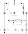
- eine Blockdarstellung einer besonders bevorzugten Ausführungsform des erfindungsgemäßen Verfahrens.
- FIG. 1
- a schematic representation of a compressed air supply system according to an embodiment of the invention;
- FIG. 2
- a block diagram of a method according to the invention; and
- FIG. 3
- a block diagram of a particularly preferred embodiment of the method according to the invention.
Bei der nachfolgenden Beschreibung bezeichnen gleiche Bezugszeichen gleiche oder vergleichbare Komponenten.In the following description, like reference characters designate the same or similar components.
In der
Ein Druckluftversorgungssystem 10 für ein Kraftfahrzeug weist einen Kompressor 12 auf. Der Kompressor 12 kann durch einen nicht gezeigten Motor des Fahrzeugs betrieben werden und stellt Druckluft bereit. Mit dem Kompressor verbunden ist eine Luftvorbereitungseinheit 14, die insbesondere zum Filtern und Trocknen der Luft geeignet ist.
Luft kann von dem Kompressor 12 zur Luftvorbereitungseinheit 14 strömen, wo ihr Wasser und Verunreinigungen entzogen werden.A compressed
Air may flow from the
Die Luftvorbereitungseinheit 14 ist ferner mit einer Betriebseinheit 16 verbunden, die eine Ventilvorrichtung umfassen kann. Stromab der Betriebseinheit 16 kann optional ein Druckregulator 18 vorgesehen sein, der dazu geeignet ist, den Druck aus der Betriebseinheit 16 auf ein gewünschtes Maß einzustellen.The
Ebenfalls optional kann sich hinter dem Druckregulator 18 ein Druckluftverteiler 20 befinden, der zum Verteilen von Luft auf ein Druckluftreservoir 22 vorgesehen ist. Der Druckluftverteiler 20 kann beispielsweise als ein Mehrkreisschutzventil ausgeführt sein.Also optionally may be located behind the
Das Druckluftreservoir 22 kann mehrere voneinander getrennte Kammern aufweisen, oder nur eine einzige Kammer. Sind mehrere Kammern vorgesehen, können diese auch räumlich voneinander getrennt über das Fahrzeug verteilt sein. Der Druckluftverteiler 20 verfügt über geeignete Leitungsverbindungen zu dem Druckluftreservoir 22, um dieses zu Befüllen. Im gezeigten Beispiel sind zwei Leitungsverbindungen vom Druckluftverteiler 20 zu dem Druckluftreservoir 22 vorgesehen.The
Alternativ kann die Betriebseinheit 16 auch direkt mit dem Druckluftreservoir 22 verbunden sein beziehungsweise können dem Druckregulator 18 und/oder dem Druckluftverteiler 20 entsprechende Komponenten Teil der Betriebseinheit 16 sein.Alternatively, the operating
Das Druckluftreservoir 22 ist mit einem oder mehreren Druckluftverbrauchern 24 derart verbunden, dass es den Verbrauchern 24 Druckluft bereitstellen kann. Sind mehrere Verbraucher 24 an das Druckluftreservoir 22 gekoppelt, so sind diese beispielsweise jeweils mit verschiedenen Kammern des Druckluftreservoirs verbunden. In dem Fall, dass das Kraftfahrzeug mit einem pneumatischen Bremssystem ausgestattet ist, stellt dieses einen äußerst wichtigen, weil sicherheitsrelevanten Verbraucher 24 dar.The
In diesem Beispiel ist ein Hilfsreservoir 25 für Druckluft vorgesehen, das mit der Betriebseinheit 16 verbunden ist. Auch dieses Reservoir 25 kann wie oben beschrieben über mehrere Kammern verfügen.In this example, an
Ferner verfügt das Druckluftversorgungssystem 10 über eine Druckluftsteuereinrichtung 26. Diese kann beispielsweise einen Mikroprozessor oder andere beziehungsweise weitere elektronische Komponenten aufweisen und ist zum Empfangen von Signalen mit einer Fahrzeugelektronik 28 verbunden. Diese Verbindung kann beispielsweise über einen CAN-Bus, einen LIN-Bus oder einen FlexRay-Bus erfolgen. Wichtig ist, dass die Druckluftsteuereinrichtung 26 in die Lage versetzt ist, ein entsprechendes Signal zu empfangen, wenn sich das Fahrzeug in einem Betriebszustand Schubphase befindet. Dabei ist auch vorstellbar, dass die Druckluftsteuereinrichtung 26 statt mit einer herkömmlichen Fahrzeugelektronik mit Sensoren verbunden ist, die einen solchen Zustand zu erfassen vermögen, beispielsweise durch Überwachung des Motormoments, und ein geeignetes Signal an die Druckluftsteuereinrichtung 26 übermitteln, wenn ein Betriebszustand Schubphase vorliegt. Selbstverständlich kann die Steuereinrichtung 26 auch für eine Zwei-Wege-Kommunikation mit der Fahrzeugelektronik 28 und/oder weiteren Komponenten ausgelegt sein, um beispielsweise Informationen über den Zustand des Druckluftversorgungssystems 10 an die Elektronik 28 weitergeben zu können. Als zur Steuereinrichtung 26 gehörig werden außerdem nicht ausdrücklich anderen Einheiten zugeordnete pneumatische Komponenten angesehen, die für bestimmte Steuerfunktion von Luftströmen notwendig sind, wie etwa bestimmte Ventile.Furthermore, the compressed
Die Steuereinrichtung 26 ist zur Ansteuerung des Kompressors 12 mit diesem verbunden. Insbesondere vermag es die Steuereinrichtung 26, den Kompressor zu starten oder anzuhalten. Auch die Luftvorbereitungseinheit 14 kann von der Steuereinrichtung 26 gesteuert werden, etwa um auf bekannte Art eine Regenerierung der Luftvorbereitungseinheit 14 durchzuführen, um diese von aus der Druckluft gefilterten Verunreinigungen und Feuchtigkeit zu befreien.The
Die Betriebseinheit 16 ist ebenfalls mit der Steuereinrichtung 26 verbunden, so dass die Steuereinrichtung 26 einen Luftstrom durch die Betriebseinheit 16 zu steuern vermag. Insbesondere kann die Betriebseinheit 16 zum Beispiel mindestens ein durch die Steuereinrichtung 26 ansteuerbares Magnetventil aufweisen, das zum Verbinden des Kompressors 12 mit dem Druckluftreservoir 22 geöffnet werden kann. Wenn das Magnetventil geschlossen ist, ist die Verbindung zwischen dem Kompressor 12 und dem Druckluftreservoir 22 unterbrochen und dem Druckluftreservoir 22 kann keine Luft von dem Kompressor 12 zugeführt werden. Die Betriebseinheit 16 kann ferner Vorrichtungen zum Regulieren des Drucks der Druckluft aufweisen. Außerdem kann die Betriebseinheit 16 dazu eingerichtet sein, nach Maßgabe der Steuereinrichtung 26 einen Luftstrom vom Kompressor 12 zum Hilfsreservoir 25 zu steuern.The operating
Über die Betriebseinheit 16 kann ferner eine Verbindung zum Strömen von Luft zwischen dem Hilfsreservoir 25 und dem Druckluftreservoir 22 gegeben sein. Alternativ kann eine direkte Verbindung zwischen dem Druckluftreservoir 22 und dem Hilfsreservoir 25 vorgesehen sein. Es ist zweckmäßig, in der Verbindung zwischen den Reservoiren 22 und 25 ein Rückschlagventil derart vorzusehen, dass ein Strömen von Luft vom Druckluftreservoir 22 zum Hilfsreservoir 25 verhindert ist. Diese Verbindung ist dazu vorgesehen, es zu ermöglichen, dass Druckluft vom Hilfsreservoir 25 zum Druckluftreservoir 22 strömt, wenn ein Druck Ph im Hilfsreservoir 25 über dem Druck Pr im Druckluftreservoir 22 liegt. Es ist vorteilhaft, wenn die Steuereinrichtung 26 derart ausgestaltet ist, dass sie einen Luftstrom vom Reservoir 25 zum Druckluftreservoir 22 steuern kann und nur zulässt, wenn der Druck Pr im Druckluftreservoir 22 unterhalb eines Umfülldrucks PU liegt, welcher insbesondere ein Solldruck Prs oder ein Maximalsolldruck Prmax sein kann. Ein Befüllen des Druckluftreservoirs 22 findet nur solange statt, bis dieses den Maximalsolldruck Prmax aufweist. Dazu kann zwischen dem Hilfsreservoir 25 und dem Druckluftreservoir 22 vorzugsweise ein Druckbegrenzungsventil vorgesehen sein, das dazu eingerichtet ist, zu verhindern, dass das Druckluftreservoir 22 von dem Hilfsreservoir 25 auf einen Druck über dem Maximalsolldruck Prmax befüllt wird.Furthermore, a connection for the flow of air between the
In der gezeigten Variante ist die Betriebseinheit 16 also dazu ausgelegt, einen Luftstrom zwischen Kompressor 12, Druckluftreservoir 22 und Hilfsreservoir 25 nach Maßgabe der Steuereinrichtung 26 zu steuern.In the variant shown, the operating
Das System ist dazu ausgelegt, den Druck Pr, Ph in den Reservoiren 22, 25 zu überwachen. Dies kann auf bekannte Art über Sensoren, beispielsweise Drucksensoren, zur Überwachung des Reservoirs 22 beziehungsweise Hilfsreservoirs 25 geschehen, die zur Signalübertragung an die Steuereinrichtung 26 vorgesehen sind. Alternativ können auch Sensoren vorgesehen sein, die mit der restlichen Fahrzeugelektronik 28 kommunizieren. Das System ist dann zweckmäßigerweise zum Weitergeben von den Druck betreffenden Informationen an die Steuereinrichtung 26 über die Verbindung der Fahrzeugelektronik 28 mit der Steuereinrichtung 26 ausgelegt.The system is configured to monitor the pressure P r , P h in the
Die Steuereinrichtung 26 und die Betriebseinheit 16 sowie optional die Luftvorbereitungseinheit 14, der Druckregulator 18 und/oder der Verteiler 20 können zusammen als eine Druckversorgungseinheit 30 angesehen werden. Es ist besonders vorteilhaft, eine solche Druckversorgungseinheit 30 so auszubilden, dass sie als ein Standardmodul zwischen einen Kompressor 12 und ein Druckluftreservoir 22 sowie, falls vorhanden, ein Hilfsreservoir 25 eingebaut werden kann.The
Im Folgenden werden mit Bezug auf
Die Steuereinrichtung 26 ist dazu ausgelegt, in Schritt S10 zu Erfassen, ob ein Betriebszustand Schubphase des Fahrzeugs vorliegt, beispielsweise indem sie ein bestimmtes Signal von der Fahrzeugelektronik 28 empfängt. Ist dies nicht der Fall, geht sie zu Schritt S200 über.The
In Schritt S200 kann die Befüllung des Reservoirs beendet werden, indem der Kompressor 12 gestoppt wird und die Betriebseinheit 16 zum Abbruch der Verbindung zwischen Druckluftreservoir 22 und Kompressor 12 beziehungsweise gegebenenfalls zwischen Kompressor 12 und Hilfsreservoir 25 angesteuert wird. Insbesondere kann vorgesehen sein, weitere Bedingungen zu prüfen, ob eine Befüllung trotz Beendigung der Schubphase weitergeführt werden soll, etwa wenn der Druck im Reservoir 22 unterhalb eines weiteren definierten Minimalsolldrucks Prmin liegt, der ein Befüllen mit Druckluft auch bei belastetem Motor notwendig macht. Ferner kann von Schritt S200 die Prozedur erneut begonnen werden. Auch kann hier in ein weiteres parallel durchgeführtes Verfahren zur Steuerung des Druckluftsystems verzweigt werden.In step S200, the filling of the reservoir can be stopped by the
Liegt ein Betriebszustand Schubphase vor, erfasst die Steuereinrichtung 26 in Schritt S20, ob der Druck Pr im Druckluftreservoir unterhalb eines bestimmten Solldrucks Prs liegt. Der Solldruck Prs kann insbesondere gleich dem Minimalsolldruck Prmin gesetzt sein. Gilt Pr < Prs, verzweigt die Prozedur zu S30, ansonsten zu S70.If an operating state of overrun phase is present, the
In Schritt S30 steuert die Steuereinrichtung 26 den Kompressor 12 derart an, dass er startet und Luft zu komprimieren beginnt. Außerdem wird die Betriebseinheit 16 in Schritt S40 derart gesteuert, dass Luft vom Kompressor 12 über die Luftvorbereitungseinheit 14 und die Betriebseinheit 16 sowie den Druckregulator 18 und den Verteiler 20 in das Druckluftreservoir 22 strömen kann. Die Schritte S30 und S40 lassen sich in beliebiger Reihenfolge ausführen. Es kann dabei vorteilhaft sein, zuerst den Kompressor 12 zu starten, da dieser in der Regel nicht sofort mit einer eingestellten Leistung wirkt.In step S30, the
In Schritt S50 wird überprüft, ob immer noch eine Schubphase vorliegt. Ist dies nicht der Fall, wird zu Schritt S200 übergegangen. Liegt weiterhin eine Schubphase vor, wird in Schritt S60 geprüft, ob der Maximalsolldruck Prmax erreicht ist, über den hinaus das Druckluftreservoir 22 nicht befüllt werden soll. Ist dies nicht der Fall, wird die Befüllung mit Druckluft fortgesetzt und wieder zu Schritt S50 verzweigt. Ist der Maximalsolldruck Prmax erreicht, wird in Schritt S65 die Verbindung zwischen Druckluftreservoir 22 und Kompressor 12 durch die Betriebseinheit 16 nach Maßgabe der Steuereinrichtung 26 unterbrochen.In step S50 it is checked whether there is still a coasting phase. If this is not the case, then step S200 is proceeded to. If there is still a coasting phase, it is checked in step S60 whether the maximum nominal pressure P rmax has been reached beyond which the
Der optionale Schritt S70 überprüft, ob noch eine Schubphase vorliegt. Liegt eine Schubphase vor, wird zu Schritt S75 verzweigt. Ansonsten verzeigt das Verfahren zu Schritt S200.The optional step S70 checks whether there is still a coasting phase. If there is a coasting phase, a branch is made to step S75. Otherwise, the process branches to step S200.
In Schritt S75 erfasst die Steuereinrichtung 26, ob der Druck Ph im Hilfsreservoir 25 unterhalb eines bestimmten Hilfssolldrucks Phs liegt. Ist dies der Fall, überprüft die Steuereinrichtung 26 in Schritt S80, ob der Kompressor 12 läuft und startet ihn gegebenenfalls (Schritt S82, von dem es zu Schritt S85 weitergeht, nachdem der Kompressor gestartet wurde). Ansonsten wird von Schritt S80 direkt zu Schritt S85 verzweigt.In step S75, the
Ergibt die Überprüfung in Schritt S75, dass der Druck Ph im Hilfsreservoir 25 zumindest dem Hilfssolldruck Phs gleich ist oder darüber liegt, wird zu Schritt S200 verzeigt.If the check in step S75 reveals that the pressure P h in the
In Schritt S85, der auf Schritt S80 oder Schritt S82 folgt, wird die Betriebseinheit 16 dazu angesteuert, ein Befüllen des Hilfsreservoirs 25 zu ermöglichen.In step S85, which follows step S80 or step S82, the
Dann überprüft die Steuereinrichtung 26, ob immer noch eine Schubphase vorliegt (S90). Ist dies nicht der Fall, verzweigt die Prozedur zu Schritt S200. Ansonsten geht das Verfahren zu Schritt S95 über.Then, the
Schritt S95 überprüft, ob der Druck Ph im Hilfsreservoir 25 einen Maximalsolldruck Phmax erreicht hat. Ist dies nicht der Fall, wird der Kompressor 12 weiter zum Befüllen des Hilfsreservoirs 25 betrieben und zu Schritt S90 verzweigt. Ist der Maximalsolldruck Phmax erreicht, wird zu Schritt S200 übergegangen. Es kann zweckmässig sein, den Hilfssolldruck Phs und den Maximalsolldruck Phmax so einzustellen, dass sie gleich sind. Dann wird das Hilfsdruckreservoir 25 befüllt, wenn sein Druck unter dem ihm zugeordneten Maximalsolldruck liegt.Step S95 checks whether the pressure P h in the
Die Reihenfolge der Schritte in dieser Prozedur ist zweckmäßig gewählt, aber nicht notwendig. Insbesondere können die verschiedenen Überprüfungsschritte des Erfassens der Schubphase beziehungsweise eines Druck in der Reihenfolge vertauscht werden oder parallel zueinander durchgeführt werden. Auch ist es nicht notwendig, zuerst das Druckluftreservoir 22 zu befüllen, und dann das Hilfsreservoir 25. Auch die umgekehrte Reihenfolge ist vorstellbar. Alternativ können auch beide Reservoirs gleichzeitig aufgefüllt werden.The order of steps in this procedure is convenient but not necessary. In particular, the various checking steps of detecting the pushing phase or a pressure in the order can be interchanged or carried out in parallel. Also, it is not necessary to first fill the
Die Solldrücke in den Reservoirs können nach Bedarf eingestellt sein. Es ist dabei vorteilhaft, wenn Phmax > Prmax gilt, das Hilfsreservoir 25 also bis zu einem höheren Druck befüllt wird als das Druckluftreservoir 22. Dann lässt sich ein schnelles Befüllen des Druckluftreservoir 22 durch einen Luftstrom vom Hilfsreservoir 25 besonders leicht einrichten. Um ein möglichst konstantes Druckniveau Pr im Druckluftreservoir 22 aufrecht zu erhalten, ist es zweckmäßig, den Umfülldruck Pu=Prs zu setzen, damit ein Druckabfall im Druckluftreservoir 22 auf einen Druck Pr unterhalb des gewünschten Niveaus schnell durch das Hilfsreservoir ausgeglichen wird. Der Solldruck Prs ist zweckmäßigerweise so gewählt, das eine zuverlässige Funktion des beziehungsweise der an das Druckluftreservoir 22 angeschlossenen Verbraucher 24 gewährleistet ist. Im einfachsten Fall gelten Prmin=Prs und Phmax=Phs, d.h. die Sollwerte der Drücke, ab denen eine Zufuhr von Druckluft erfolgen soll, entsprechen für das Druckluftreservoir 22 dem Minimaldruck und für das Hilfsreservoir 5 dem Maximalsolldruck Phmax. Es kann selbstverständlich zweckmässig sein, die Sollwerte anders einzustellen. Beispielsweise kann der Sollwert Prs für das Druckluftreservoir 22 auf den Maximalsolldruck eingestellt sein; dann würde eine Druckluftzufuhr deutlich häufiger erfolgen als im vorgenannten Fall. Auch ist es möglich, die Sollwerte je nach Fahrsituation dynamisch einzustellen. So ist ein niedriger Druck Prs im Druckluftreservoir 22 energetisch günstig und belastet das Druckluftversorgungssystem weniger als ein hoher Druck. Ist aber beispielsweise zu erwarten, dass eine hohe Bremsleistung oder eine langandauernde Bremsleistung verlangt wird (beispielsweise wenn durch Verwenden eines Navigationssystems der Fahrzeugelektronik bekannt ist, dass ein langes Gefälle bevorsteht), kann es insbesondere dann, wenn ein pneumatisches Bremssystem mit dem Druckluftversorgungssystem verbunden ist, zweckmässig sein, den Sollwert des Druckes Prs im Druckluftreservoir 22 und gegebenenfalls entsprechend den Hilfssolldruck Phs des Hilfsreservoir 25 zu erhöhen. Dies kann schon vor Erreichen des Gefälles geschehen.The desired pressures in the reservoirs may be adjusted as needed. It is advantageous if P hmax > P rmax applies, the
In Schritt S300 wird überprüft, ob der Druck Pr im Druckluftreservoir 22 unter dem Mindestdruck Prmin liegt. Ist dies nicht der Fall, verzeigt das Verfahren nach S430. Gilt jedoch Pr<Prmin (beziehungsweise Pr<=Prmin), wird in Schritt S310 geprüft, ob der Druck Pr im Druckluftreservoir 22 unter dem Druck Ph im Hilfsreservoir 25 liegt.In step S300 it is checked whether the pressure P r in the
Ist dies nicht der Fall, wird in Schritt S320 festgestellt, ob der Kompressor 12 in Betrieb ist, und in Schritt S330 wird der Kompressor 12 gestartet, falls er laut dem Ergebnis aus Schritt S320 noch nicht läuft.
Ansonsten wird von Schritt S320 direkt zu Schritt S340 verzweigt.If this is not the case, it is determined in step S320 whether the
Otherwise, the process branches from step S320 directly to step S340.
In Schritt S340 wird das Druckluftreservoir 22 vom Kompressor 12 mit Druckluft befüllt. Nachfolgend wird in Schritt S350 festgestellt, ob der Druck Pr im Druckluftreservoir 22 geringer ist als der Maximaldruck Prmax. Ist dies der Fall, wird zu Schritt S340 zurückverzweigt.In step S340, the
Ist der Druck Pr jedoch schon auf den Druck Prmax angestiegen, geht es zu Schritt S360, in dem überprüft wird, ob eine Schubphase vorliegt. Falls nein, wird in Schritt S370 der Kompressor 12 abgeschaltet und das Verfahren kehrt zum Anfang zurück. Ansonsten wird zu S300 zurückverzweigt.However, if the pressure P r has already risen to the pressure P rmax , it goes to step S360, in which it is checked whether a coasting phase is present. If not, the
Wird in Schritt S310 festgestellt, dass der Druck Pr im Druckluftreservoir 22 unter dem Druck Ph im Hilfsreservoir 25 liegt, wird in Schritt S380 die Zufuhr vom Hilfsreservoir 25 zum Druckluftreservoir 22 geöffnet und in Schritt S390 wird nachfolgend das Druckluftreservoir 22 vom Hilfsreservoir 25 mit Druckluft befüllt.If it is determined in step S310 that the pressure P r in the
In Schritt S400 wird überprüft, ob der Druck im Druckluftreservoir 22 noch unterhalb des Maximalsolldrucks Prmax liegt. Ist dies so, wird in Schritt S410 festgestellt, ob der Druck Ph im Hilfsreservoir 25 größer ist als der Druck Pr im Druckluftreservoir 22. Falls ja, verzweigt das Verfahren zurück zu Schritt S390, um das Druckluftreservoir 22 weiter mit Druckluft aus dem Hilfsreservoir 25 zu befüllen. Reicht der Druck Ph im Hilfsreservoir 25 nicht mehr aus, wird in Schritt S420 die Verbindung vom Hilfsreservoir 25 zum Druckluftreservoir 22 unterbrochen und die Luftzufuhr geschlossen. Ergibt sich in Schritt S400 jedoch, der Druck Pr im Druckluftreservoir 22 schon beim Maximalsolldruck Prmax liegt, verzweigt das Verfahren von Schritt S400 direkt zu Schritt S420. Danach wird zum Anfang des Verfahrens zurückverzweigt.In step S400 it is checked whether the pressure in the
Dieser Zweig des Verfahrens stellt sicher, dass das Druckluftreservoir 22 auf jeden Fall auf den Mindestdruck Prmin gebracht wird, indem entweder das Hilfsdruckreservoir 25 zum Auffüllen des Druckluftreservoirs 22 verwendet wird, oder der Kompressor 12.This branch of the method ensures that the
Ergibt die Überprüfung in Schritt S300 hingegen, dass der Druck Pr im Druckluftreservoir 22 ausreichend hoch ist, er also größer ist als der Minimaldruck Prmin, verzeigt das Verfahren zu Schritt S430. In Schritt S430 wird überprüft, ob eine Schubphase vorliegt. Wenn dies nicht der Fall ist, wird zum Anfang des Verfahrens zurückverzweigt.
Liegt hingegen eine Schubphase vor, wird in Schritt S440 festgestellt, ob ferner der Druck Ph im Hilfsreservoir 25 unter dem Hilfssolldruck Phs liegt. Ist dies nicht der Fall, wird ebenfalls zum Anfang des Verfahrens zurückverzweigt. Ansonsten wird analog zu den Schritten S320 bis S340 überprüft, ob der Kompressor 12 läuft (Schritt S450), der Kompressor 12 gestartet, wenn dies nicht der Fall ist (Schritt S460), und das Hilfsreservoir 25 mit Hilfe des Kompressors 12 aufgefüllt (Schritt S470). Dabei wird der Kompressor 12 in diesem Zweig des Verfahrens unter Ausnutzung der Schubphase betrieben; in dieser Ausführungsform ist nicht vorgesehen, das Hilfsreservoir 25 aufzufüllen, wenn keine Schubphase vorliegt. Selbstverständlich kann aber vorgesehen sein, dass Hilfsreservoir 25 auch dann aufzufüllen, wenn keine Schubphase vorliegt und die Motorleistung dazu verwendet werden muss, etwa dann, wenn es über einen bestimmten längeren Zeitraum einen Druck unterhalb des Solldrucks Phs aufweist.On the other hand, if the check in step S300 indicates that the pressure P r in the
If, on the other hand, there is a coasting phase, it is determined in step S440 whether, furthermore, the pressure P h in the
Schritt S480 ist dazu vorgesehen, festzustellen, ob der Druck im Druckluftreservoir 22 unter dem Minimalsolldruck Prmin liegt. Ist dies der Fall, geht das Verfahren zum Anfang über und das Druckreservoir 22 kann befüllt werden. Falls nicht, wird in Schritt S490 festgestellt, ob der Druck Ph unterhalb des Hilfssolldrucks Phs liegt. Ist dies der Fall, wird in Schritt S500 geprüft, ob immer noch eine Schubphase vorliegt. Hat sich die Fahrzeugsituation dahingehend geändert, dass keine Schubphase mehr vorliegt, verzweigt das Verfahren wieder zum Anfang. Befindet sich das Fahrzeug hingegen in einer Schubphase, wird zu Schritt S470 zurückverzweigt und das Hilfsreservoir 25 wird weiter befüllt.Step S480 is for determining whether the pressure in the
Ergibt Schritt S490, dass der Druck Ph im Hilfsreservoir 25 den Solldruck Phs erreicht hat, so wird in Schritt S510 der Kompressor 12 abgeschaltet und das Verfahren beginnt erneut.If step S490 indicates that the pressure P h in the
Auch für das eben beschriebene Verfahren gelten die weiter oben gemachten Bemerkungen bezülich der Werte der Solldrucke. In den einzelnen Schritten, in denen der Druck in den Reservoirs überprüft wird, muss bei Verwendung eines anderen Wertes für den Solldruck Prs als Prmin gegebenenfalls Prmin durch Prs ersetzt werden.The remarks made above regarding the values of the setpoint pressures also apply to the method just described. In the individual steps, in which the pressure in the reservoirs is checked, must when using a different value for the target pressure P rs as P rmin P rmin optionally replaced by P rs .
Die hier beschriebene Vorrichtung und insbesondere die beschrieben Verfahren können durch Ausnutzen der Schubphasen von Fahrzeugen zum Betreiben des Kompressors Kraftstoff einsparen. Insbesondere bei Fahrzeugen mit Druckluftbremssystemen wird ein Befüllen des Druckluftreservoir bei einem Normalbetrieb des Motors allerdings nicht vollständig ersetzbar sein, um immer ausreichend Druckluft zum Bremsen zur Verfügung zu haben. Die erfindungsgemäßen Vorrichtungen und Verfahren schließen daher das Verwenden eines herkömmlichen Systems nicht aus, sondern können zusätzlich zu einem solchen verwendet werden.The apparatus described herein, and in particular the described methods, can save fuel by exploiting the coasting periods of vehicles to operate the compressor. In particular, in vehicles with compressed air brake systems, however, a filling of the compressed air reservoir in a normal operation of the engine will not be completely replaceable to always have enough compressed air available for braking. The devices and methods of the invention therefore do not exclude the use of a conventional system, but may be used in addition to such.
Auf jeden Fall müssen die für den Betrieb verlangten Sicherheitserfordernisse erfüllt sein, etwa was den Druck im Druckluftreservoir für ein Druckluftbremssystem angeht. Dieser sollte den erforderlichen Mindestdruck nicht unterschreiten. Dabei versteht es sich von selbst, dass unabhängig vom Betriebszustand jederzeit der Kompressor des Druckluftsystems eingesetzt werden kann, um den erforderlichen Druck im Druckluftreservoir herzustellen.In any case, the safety requirements required for operation must be met, such as the pressure in the compressed air reservoir for a compressed-air brake system. This should not fall below the required minimum pressure. It goes without saying that regardless of the operating state of the compressor of the compressed air system can be used at any time to produce the required pressure in the compressed air reservoir.
Die in der vorstehenden Beschreibung, in den Zeichnungen sowie in den Ansprüchen offenbarten Merkmale der Erfindung können sowohl einzeln als auch in beliebiger Kombination für die Verwirklichung der Erfindung wesentlich sein.The features of the invention disclosed in the foregoing description, in the drawings and in the claims may be essential to the realization of the invention both individually and in any combination.
- 1010
- DruckluftversorgungssystemCompressed air supply system
- 1212
- Kompressorcompressor
- 1414
- LuftvorbereitungseinheitAir preparation unit
- 1616
- Betriebseinheitoperating unit
- 1818
- Druckregulatorpressure regulator
- 2020
- DruckluftverteilerCompressed air distribution
- 2222
- DruckluftreservoirCompressed air reservoir
- 2424
- DruckluftverbraucherAir consumers
- 2525
- Hilfsreservoirauxiliary reservoir
- 2626
- DruckluftteuereinrichtungCompressed air control means
- 2828
- Fahrzeugelektronikvehicle electronics
- 3030
- DruckluftversorgungseinrichtungCompressed air supply system
Claims (3)
- A compressed air supply device (30) for a motor vehicle comprising an internal combustion engine, at least one compressed air tank (22, 25) having a predetermined reference pressure (Prs, Phs) and a compressor (12), which is or can be connected to the compressed air tank (22, 25) for the supply of compressed air; wherein the compressed air supply device (10) comprises a compressed air control device (26) which is able to control a supply of compressed air from the compressor (12) to the at least one compressed air tank (22, 25) and is, furthermore, configured to detect a coasting operating state of the vehicle; wherein the compressed air control device (26) is configured to control a supply of compressed air from the compressor (12) to the at least one compressed air tank (22, 25) when the air pressure in the compressed air tank (22, 25) is at a pressure (Pr, Ph) below the reference pressure (Prs, Phs) in order to detect the coasting operating state; characterised in that the compressed air control device (26) is configured to control the supply of compressed air from the compressor (12) to the auxiliary tank (25) when compressed air in an auxiliary tank (25) that is or can be connected to the compressor (12) is at a pressure (Ph) below an auxiliary reference pressure (Phs); and wherein the compressed air control device (26) is, in addition, configured to control a supply of compressed air from the auxiliary tank (25) to the compressed air tank (22) when the pressure (Ph) in the auxiliary tank (25) is greater than the pressure (Pr) in the compress air tank (22).
- A compressed air supply system (10) for a motor vehicle having an internal combustion engine and comprising:- at least one compressed air tank (22, 25) having a predetermined reference pressure (Prs, Phs);- a compressor (12) that is or can be connected to the supply of compressed air to the compressed air tank (22, 25);- a compressed air supply device (30) having a compressed air control device (26) which is able to control a supply of compressed air from the compressor (12) to the at least one compressed air tank (22, 25) and is, in addition, configured to detect a coasting operating state of the vehicle;wherein the compressed air control device (26) is configured to control a supply of compressed air from the compressor (12) to the at least one compressed air tank (22, 25) when the compressed air in the compressed air tank (22, 25) is at a pressure (Pr, Ph) below the reference pressure (Prs, Phs) in order to detect the coasting operating state; wherein, in addition, the compressed air supply system comprises at least one auxiliary tank (25) for compressed air with a predetermined auxiliary reference pressure (Phs) that is or can be connected to the compressed air tank (22) and the compressor (12); characterised in that the compressed air control device (26) is, in addition, configured to control a supply of compressed air from the compressor (12) to the at least one auxiliary tank (25) when the compressed air in the auxiliary tank (25) is at a pressure (Ph) under the auxiliary reference pressure (Phs); wherein the compressed air control device (26) is, in addition, configured to control a supply of compressed air from the auxiliary tank (25) to the compressed air tank (22) when the pressure (Ph) in the auxiliary tank is greater than the pressure (Pr) in the compressed air tank (22).
- A process for controlling a compressed air supply system (10) for a motor vehicle comprising the following steps:- detection (S10), by a compressed air control device (26), of whether a vehicle is in a coasting operating state;- detection (S20, S75), by the compressed air control device (26), of whether a pressure (Pr, Ph) in a compressed air tank (22) is below a predetermined reference pressure (Prs, Phs) ; and- control, by the compressed air control device (26), of a supply of compressed air from a compressor (12) to the compressed air tank (22, 25) when a coasting operating state has been detected and a pressure (Pr, Ph) below the reference pressure (Prs, Phs) has been detected in the pressure tank (22, 25);- detection (S75), by the compressed air control device (26), of whether a pressure (Ph) in an auxiliary tank (25) is below a predetermined auxiliary reference pressure (Phs); and- control (S80), by the compressed air control device (26), of a supply of compressed air from the compressor (12) to the auxiliary tank (25) when a coasting operating state has been detected and a pressure (Ph) in the auxiliary tank (25) below the auxiliary reference pressure (Phs) has been detected;- control, by the control device (26), of a supply of compressed air from the auxiliary tank (25) to the compressed air tank (22) when the pressure (Ph) in the auxiliary tank (25) is greater than the pressure (Pr) in the pressure tank (22).
Applications Claiming Priority (1)
| Application Number | Priority Date | Filing Date | Title |
|---|---|---|---|
| DE102009017903A DE102009017903A1 (en) | 2009-04-17 | 2009-04-17 | Compressed air supply system for a motor vehicle |
Publications (2)
| Publication Number | Publication Date |
|---|---|
| EP2241488A1 EP2241488A1 (en) | 2010-10-20 |
| EP2241488B1 true EP2241488B1 (en) | 2018-03-14 |
Family
ID=42244921
Family Applications (1)
| Application Number | Title | Priority Date | Filing Date |
|---|---|---|---|
| EP10160154.0A Not-in-force EP2241488B1 (en) | 2009-04-17 | 2010-04-16 | Pressurised air supply system for a motor vehicle |
Country Status (2)
| Country | Link |
|---|---|
| EP (1) | EP2241488B1 (en) |
| DE (1) | DE102009017903A1 (en) |
Families Citing this family (4)
| Publication number | Priority date | Publication date | Assignee | Title |
|---|---|---|---|---|
| DE102012105769A1 (en) * | 2012-06-29 | 2014-04-10 | Dr. Ing. H.C. F. Porsche Aktiengesellschaft | Motor vehicle i.e. motor car, has memory connected with vehicle-internal consumer unit and adapted for storing sucked and/or compressed air, where vehicle-internal consumer unit is supplied with air based on demand from memory |
| DE102013000275A1 (en) * | 2013-01-09 | 2014-07-10 | Wabco Gmbh | Method and device for controlling a compressed air brake system of a vehicle combination |
| US10046746B2 (en) | 2014-07-02 | 2018-08-14 | Volvo Truck Corporation | Method for piloting a braking system of a vehicle, braking system and vehicle comprising such a braking system |
| DE102016011011A1 (en) | 2016-09-09 | 2018-03-15 | Faun Umwelttechnik Gmbh & Co. Kg | Energy recovery device for commercial vehicles with compressed air brake system |
Family Cites Families (3)
| Publication number | Priority date | Publication date | Assignee | Title |
|---|---|---|---|---|
| US6074462A (en) * | 1997-12-18 | 2000-06-13 | Alliedsignal Truck Brake Systems Co. | Air dryer reservoir module components |
| GB9912681D0 (en) * | 1999-06-02 | 1999-07-28 | Wabco Automotive Uk | Vehicle air braking systems |
| FR2835787B1 (en) * | 2002-02-14 | 2004-10-22 | Renault Vehicules Ind | METHOD FOR DRIVING A COMPRESSOR DRIVEN BY THE ENGINE OF A VEHICLE |
-
2009
- 2009-04-17 DE DE102009017903A patent/DE102009017903A1/en not_active Ceased
-
2010
- 2010-04-16 EP EP10160154.0A patent/EP2241488B1/en not_active Not-in-force
Non-Patent Citations (1)
| Title |
|---|
| None * |
Also Published As
| Publication number | Publication date |
|---|---|
| DE102009017903A1 (en) | 2010-10-21 |
| EP2241488A1 (en) | 2010-10-20 |
Similar Documents
| Publication | Publication Date | Title |
|---|---|---|
| EP2164734B1 (en) | Braking system for a utility vehicle that can be pneumatically coupled to a trailer, and method for operating such a braking system in the event of defects | |
| EP2288524B1 (en) | Brake device for a motor vehicle comprising at least three brake circuits | |
| DE102007037346B4 (en) | Control unit for a brake system of a commercial vehicle and method for controlling a brake system | |
| EP2754594B1 (en) | Method and device for controlling a compressed air braking system of a vehicle combination | |
| EP2570316B1 (en) | Compressed air supply device for a commercial vehicle | |
| EP2108557B1 (en) | Method and device for controlling the pressure of an EBS braking system if a closed loop malfunctions | |
| DE102008000747A1 (en) | Method for switching control of an automated stepped gearbox | |
| EP2039576B1 (en) | System with an air conditioning assembly | |
| EP2241488B1 (en) | Pressurised air supply system for a motor vehicle | |
| EP1508488B1 (en) | Installation of compressed air production for a vehicle and method of operating the same | |
| WO2006120108A1 (en) | Braking aid comprising an intensification factor used during emergency brake control | |
| DE102019219793A1 (en) | Hydraulic motor vehicle brake system, method for operating the same and control device therefor | |
| EP2463127B1 (en) | Compressed air supply system for at least one initial compressed air consumer circuit, compressed air system and method for controlling a compressed air supply system and/or controlling a compressed air system | |
| DE102008049739A1 (en) | Central pressure supply for auxiliary drives | |
| EP3256356B1 (en) | Electro-pneumatic service brake device of a vehicle with noise reduction during brake release and method for the control thereof | |
| DE102004021242B4 (en) | Air treatment plant and method for supplying a commercial vehicle brake system with compressed air | |
| DE102019121377A1 (en) | Tire pressure regulation system and method for operating such a system | |
| DE102004027508A1 (en) | Hydraulic brake system and method for influencing a hydraulic brake system | |
| EP3266661A1 (en) | Trailer brake system and operating methods for a trailer brake system | |
| WO2006074722A1 (en) | Pressurised medium system | |
| DE102014018125A1 (en) | Method for operating a compressed air system of a motor vehicle |
Legal Events
| Date | Code | Title | Description |
|---|---|---|---|
| PUAI | Public reference made under article 153(3) epc to a published international application that has entered the european phase |
Free format text: ORIGINAL CODE: 0009012 |
|
| AK | Designated contracting states |
Kind code of ref document: A1 Designated state(s): AT BE BG CH CY CZ DE DK EE ES FI FR GB GR HR HU IE IS IT LI LT LU LV MC MK MT NL NO PL PT RO SE SI SK SM TR |
|
| AX | Request for extension of the european patent |
Extension state: AL BA ME RS |
|
| 17P | Request for examination filed |
Effective date: 20110420 |
|
| 17Q | First examination report despatched |
Effective date: 20170124 |
|
| GRAP | Despatch of communication of intention to grant a patent |
Free format text: ORIGINAL CODE: EPIDOSNIGR1 |
|
| INTG | Intention to grant announced |
Effective date: 20171005 |
|
| GRAS | Grant fee paid |
Free format text: ORIGINAL CODE: EPIDOSNIGR3 |
|
| GRAA | (expected) grant |
Free format text: ORIGINAL CODE: 0009210 |
|
| AK | Designated contracting states |
Kind code of ref document: B1 Designated state(s): AT BE BG CH CY CZ DE DK EE ES FI FR GB GR HR HU IE IS IT LI LT LU LV MC MK MT NL NO PL PT RO SE SI SK SM TR |
|
| REG | Reference to a national code |
Ref country code: GB Ref legal event code: FG4D Free format text: NOT ENGLISH |
|
| REG | Reference to a national code |
Ref country code: CH Ref legal event code: EP Ref country code: AT Ref legal event code: REF Ref document number: 978565 Country of ref document: AT Kind code of ref document: T Effective date: 20180315 |
|
| REG | Reference to a national code |
Ref country code: IE Ref legal event code: FG4D Free format text: LANGUAGE OF EP DOCUMENT: GERMAN |
|
| REG | Reference to a national code |
Ref country code: DE Ref legal event code: R096 Ref document number: 502010014746 Country of ref document: DE |
|
| REG | Reference to a national code |
Ref country code: SE Ref legal event code: TRGR |
|
| REG | Reference to a national code |
Ref country code: NL Ref legal event code: MP Effective date: 20180314 |
|
| REG | Reference to a national code |
Ref country code: LT Ref legal event code: MG4D |
|
| PG25 | Lapsed in a contracting state [announced via postgrant information from national office to epo] |
Ref country code: ES Free format text: LAPSE BECAUSE OF FAILURE TO SUBMIT A TRANSLATION OF THE DESCRIPTION OR TO PAY THE FEE WITHIN THE PRESCRIBED TIME-LIMIT Effective date: 20180314 Ref country code: LT Free format text: LAPSE BECAUSE OF FAILURE TO SUBMIT A TRANSLATION OF THE DESCRIPTION OR TO PAY THE FEE WITHIN THE PRESCRIBED TIME-LIMIT Effective date: 20180314 Ref country code: CY Free format text: LAPSE BECAUSE OF FAILURE TO SUBMIT A TRANSLATION OF THE DESCRIPTION OR TO PAY THE FEE WITHIN THE PRESCRIBED TIME-LIMIT Effective date: 20180314 Ref country code: FI Free format text: LAPSE BECAUSE OF FAILURE TO SUBMIT A TRANSLATION OF THE DESCRIPTION OR TO PAY THE FEE WITHIN THE PRESCRIBED TIME-LIMIT Effective date: 20180314 Ref country code: HR Free format text: LAPSE BECAUSE OF FAILURE TO SUBMIT A TRANSLATION OF THE DESCRIPTION OR TO PAY THE FEE WITHIN THE PRESCRIBED TIME-LIMIT Effective date: 20180314 Ref country code: NO Free format text: LAPSE BECAUSE OF FAILURE TO SUBMIT A TRANSLATION OF THE DESCRIPTION OR TO PAY THE FEE WITHIN THE PRESCRIBED TIME-LIMIT Effective date: 20180614 |
|
| PG25 | Lapsed in a contracting state [announced via postgrant information from national office to epo] |
Ref country code: BG Free format text: LAPSE BECAUSE OF FAILURE TO SUBMIT A TRANSLATION OF THE DESCRIPTION OR TO PAY THE FEE WITHIN THE PRESCRIBED TIME-LIMIT Effective date: 20180614 Ref country code: GR Free format text: LAPSE BECAUSE OF FAILURE TO SUBMIT A TRANSLATION OF THE DESCRIPTION OR TO PAY THE FEE WITHIN THE PRESCRIBED TIME-LIMIT Effective date: 20180615 Ref country code: LV Free format text: LAPSE BECAUSE OF FAILURE TO SUBMIT A TRANSLATION OF THE DESCRIPTION OR TO PAY THE FEE WITHIN THE PRESCRIBED TIME-LIMIT Effective date: 20180314 |
|
| PG25 | Lapsed in a contracting state [announced via postgrant information from national office to epo] |
Ref country code: MT Free format text: LAPSE BECAUSE OF FAILURE TO SUBMIT A TRANSLATION OF THE DESCRIPTION OR TO PAY THE FEE WITHIN THE PRESCRIBED TIME-LIMIT Effective date: 20180314 |
|
| PG25 | Lapsed in a contracting state [announced via postgrant information from national office to epo] |
Ref country code: PL Free format text: LAPSE BECAUSE OF FAILURE TO SUBMIT A TRANSLATION OF THE DESCRIPTION OR TO PAY THE FEE WITHIN THE PRESCRIBED TIME-LIMIT Effective date: 20180314 Ref country code: EE Free format text: LAPSE BECAUSE OF FAILURE TO SUBMIT A TRANSLATION OF THE DESCRIPTION OR TO PAY THE FEE WITHIN THE PRESCRIBED TIME-LIMIT Effective date: 20180314 Ref country code: NL Free format text: LAPSE BECAUSE OF FAILURE TO SUBMIT A TRANSLATION OF THE DESCRIPTION OR TO PAY THE FEE WITHIN THE PRESCRIBED TIME-LIMIT Effective date: 20180314 Ref country code: IT Free format text: LAPSE BECAUSE OF FAILURE TO SUBMIT A TRANSLATION OF THE DESCRIPTION OR TO PAY THE FEE WITHIN THE PRESCRIBED TIME-LIMIT Effective date: 20180314 Ref country code: RO Free format text: LAPSE BECAUSE OF FAILURE TO SUBMIT A TRANSLATION OF THE DESCRIPTION OR TO PAY THE FEE WITHIN THE PRESCRIBED TIME-LIMIT Effective date: 20180314 |
|
| PG25 | Lapsed in a contracting state [announced via postgrant information from national office to epo] |
Ref country code: SM Free format text: LAPSE BECAUSE OF FAILURE TO SUBMIT A TRANSLATION OF THE DESCRIPTION OR TO PAY THE FEE WITHIN THE PRESCRIBED TIME-LIMIT Effective date: 20180314 Ref country code: SK Free format text: LAPSE BECAUSE OF FAILURE TO SUBMIT A TRANSLATION OF THE DESCRIPTION OR TO PAY THE FEE WITHIN THE PRESCRIBED TIME-LIMIT Effective date: 20180314 Ref country code: CZ Free format text: LAPSE BECAUSE OF FAILURE TO SUBMIT A TRANSLATION OF THE DESCRIPTION OR TO PAY THE FEE WITHIN THE PRESCRIBED TIME-LIMIT Effective date: 20180314 |
|
| REG | Reference to a national code |
Ref country code: CH Ref legal event code: PL |
|
| REG | Reference to a national code |
Ref country code: DE Ref legal event code: R097 Ref document number: 502010014746 Country of ref document: DE |
|
| REG | Reference to a national code |
Ref country code: BE Ref legal event code: MM Effective date: 20180430 |
|
| PG25 | Lapsed in a contracting state [announced via postgrant information from national office to epo] |
Ref country code: PT Free format text: LAPSE BECAUSE OF FAILURE TO SUBMIT A TRANSLATION OF THE DESCRIPTION OR TO PAY THE FEE WITHIN THE PRESCRIBED TIME-LIMIT Effective date: 20180716 |
|
| PLBE | No opposition filed within time limit |
Free format text: ORIGINAL CODE: 0009261 |
|
| STAA | Information on the status of an ep patent application or granted ep patent |
Free format text: STATUS: NO OPPOSITION FILED WITHIN TIME LIMIT |
|
| REG | Reference to a national code |
Ref country code: IE Ref legal event code: MM4A |
|
| PG25 | Lapsed in a contracting state [announced via postgrant information from national office to epo] |
Ref country code: MC Free format text: LAPSE BECAUSE OF FAILURE TO SUBMIT A TRANSLATION OF THE DESCRIPTION OR TO PAY THE FEE WITHIN THE PRESCRIBED TIME-LIMIT Effective date: 20180314 Ref country code: LU Free format text: LAPSE BECAUSE OF NON-PAYMENT OF DUE FEES Effective date: 20180416 Ref country code: DK Free format text: LAPSE BECAUSE OF FAILURE TO SUBMIT A TRANSLATION OF THE DESCRIPTION OR TO PAY THE FEE WITHIN THE PRESCRIBED TIME-LIMIT Effective date: 20180314 |
|
| 26N | No opposition filed |
Effective date: 20181217 |
|
| GBPC | Gb: european patent ceased through non-payment of renewal fee |
Effective date: 20180614 |
|
| PG25 | Lapsed in a contracting state [announced via postgrant information from national office to epo] |
Ref country code: BE Free format text: LAPSE BECAUSE OF NON-PAYMENT OF DUE FEES Effective date: 20180430 Ref country code: CH Free format text: LAPSE BECAUSE OF NON-PAYMENT OF DUE FEES Effective date: 20180430 Ref country code: SI Free format text: LAPSE BECAUSE OF FAILURE TO SUBMIT A TRANSLATION OF THE DESCRIPTION OR TO PAY THE FEE WITHIN THE PRESCRIBED TIME-LIMIT Effective date: 20180314 Ref country code: LI Free format text: LAPSE BECAUSE OF NON-PAYMENT OF DUE FEES Effective date: 20180430 |
|
| PG25 | Lapsed in a contracting state [announced via postgrant information from national office to epo] |
Ref country code: FR Free format text: LAPSE BECAUSE OF NON-PAYMENT OF DUE FEES Effective date: 20180514 Ref country code: IE Free format text: LAPSE BECAUSE OF NON-PAYMENT OF DUE FEES Effective date: 20180416 Ref country code: GB Free format text: LAPSE BECAUSE OF NON-PAYMENT OF DUE FEES Effective date: 20180614 |
|
| REG | Reference to a national code |
Ref country code: AT Ref legal event code: MM01 Ref document number: 978565 Country of ref document: AT Kind code of ref document: T Effective date: 20180416 |
|
| PGFP | Annual fee paid to national office [announced via postgrant information from national office to epo] |
Ref country code: SE Payment date: 20190425 Year of fee payment: 10 |
|
| PG25 | Lapsed in a contracting state [announced via postgrant information from national office to epo] |
Ref country code: AT Free format text: LAPSE BECAUSE OF NON-PAYMENT OF DUE FEES Effective date: 20180416 |
|
| PG25 | Lapsed in a contracting state [announced via postgrant information from national office to epo] |
Ref country code: TR Free format text: LAPSE BECAUSE OF FAILURE TO SUBMIT A TRANSLATION OF THE DESCRIPTION OR TO PAY THE FEE WITHIN THE PRESCRIBED TIME-LIMIT Effective date: 20180314 |
|
| PG25 | Lapsed in a contracting state [announced via postgrant information from national office to epo] |
Ref country code: HU Free format text: LAPSE BECAUSE OF FAILURE TO SUBMIT A TRANSLATION OF THE DESCRIPTION OR TO PAY THE FEE WITHIN THE PRESCRIBED TIME-LIMIT; INVALID AB INITIO Effective date: 20100416 |
|
| PG25 | Lapsed in a contracting state [announced via postgrant information from national office to epo] |
Ref country code: MK Free format text: LAPSE BECAUSE OF NON-PAYMENT OF DUE FEES Effective date: 20180314 |
|
| PG25 | Lapsed in a contracting state [announced via postgrant information from national office to epo] |
Ref country code: IS Free format text: LAPSE BECAUSE OF FAILURE TO SUBMIT A TRANSLATION OF THE DESCRIPTION OR TO PAY THE FEE WITHIN THE PRESCRIBED TIME-LIMIT Effective date: 20180714 |
|
| PGFP | Annual fee paid to national office [announced via postgrant information from national office to epo] |
Ref country code: DE Payment date: 20200423 Year of fee payment: 11 |
|
| PG25 | Lapsed in a contracting state [announced via postgrant information from national office to epo] |
Ref country code: SE Free format text: LAPSE BECAUSE OF NON-PAYMENT OF DUE FEES Effective date: 20200417 |
|
| REG | Reference to a national code |
Ref country code: DE Ref legal event code: R119 Ref document number: 502010014746 Country of ref document: DE |
|
| PG25 | Lapsed in a contracting state [announced via postgrant information from national office to epo] |
Ref country code: DE Free format text: LAPSE BECAUSE OF NON-PAYMENT OF DUE FEES Effective date: 20211103 |