EP2039576B1 - System with an air conditioning assembly - Google Patents
System with an air conditioning assembly Download PDFInfo
- Publication number
- EP2039576B1 EP2039576B1 EP08012102.3A EP08012102A EP2039576B1 EP 2039576 B1 EP2039576 B1 EP 2039576B1 EP 08012102 A EP08012102 A EP 08012102A EP 2039576 B1 EP2039576 B1 EP 2039576B1
- Authority
- EP
- European Patent Office
- Prior art keywords
- compressed air
- air
- reservoir
- conditioning unit
- vehicle
- Prior art date
- Legal status (The legal status is an assumption and is not a legal conclusion. Google has not performed a legal analysis and makes no representation as to the accuracy of the status listed.)
- Not-in-force
Links
Images


Classifications
-
- B—PERFORMING OPERATIONS; TRANSPORTING
- B60—VEHICLES IN GENERAL
- B60T—VEHICLE BRAKE CONTROL SYSTEMS OR PARTS THEREOF; BRAKE CONTROL SYSTEMS OR PARTS THEREOF, IN GENERAL; ARRANGEMENT OF BRAKING ELEMENTS ON VEHICLES IN GENERAL; PORTABLE DEVICES FOR PREVENTING UNWANTED MOVEMENT OF VEHICLES; VEHICLE MODIFICATIONS TO FACILITATE COOLING OF BRAKES
- B60T17/00—Component parts, details, or accessories of power brake systems not covered by groups B60T8/00, B60T13/00 or B60T15/00, or presenting other characteristic features
- B60T17/06—Applications or arrangements of reservoirs
-
- B—PERFORMING OPERATIONS; TRANSPORTING
- B60—VEHICLES IN GENERAL
- B60T—VEHICLE BRAKE CONTROL SYSTEMS OR PARTS THEREOF; BRAKE CONTROL SYSTEMS OR PARTS THEREOF, IN GENERAL; ARRANGEMENT OF BRAKING ELEMENTS ON VEHICLES IN GENERAL; PORTABLE DEVICES FOR PREVENTING UNWANTED MOVEMENT OF VEHICLES; VEHICLE MODIFICATIONS TO FACILITATE COOLING OF BRAKES
- B60T15/00—Construction arrangement, or operation of valves incorporated in power brake systems and not covered by groups B60T11/00 or B60T13/00
- B60T15/02—Application and release valves
- B60T15/36—Other control devices or valves characterised by definite functions
- B60T15/48—Other control devices or valves characterised by definite functions for filling reservoirs
- B60T15/50—Other control devices or valves characterised by definite functions for filling reservoirs with means for limiting or relieving pressure in reservoirs
-
- B—PERFORMING OPERATIONS; TRANSPORTING
- B60—VEHICLES IN GENERAL
- B60T—VEHICLE BRAKE CONTROL SYSTEMS OR PARTS THEREOF; BRAKE CONTROL SYSTEMS OR PARTS THEREOF, IN GENERAL; ARRANGEMENT OF BRAKING ELEMENTS ON VEHICLES IN GENERAL; PORTABLE DEVICES FOR PREVENTING UNWANTED MOVEMENT OF VEHICLES; VEHICLE MODIFICATIONS TO FACILITATE COOLING OF BRAKES
- B60T17/00—Component parts, details, or accessories of power brake systems not covered by groups B60T8/00, B60T13/00 or B60T15/00, or presenting other characteristic features
- B60T17/002—Air treatment devices
-
- B—PERFORMING OPERATIONS; TRANSPORTING
- B60—VEHICLES IN GENERAL
- B60T—VEHICLE BRAKE CONTROL SYSTEMS OR PARTS THEREOF; BRAKE CONTROL SYSTEMS OR PARTS THEREOF, IN GENERAL; ARRANGEMENT OF BRAKING ELEMENTS ON VEHICLES IN GENERAL; PORTABLE DEVICES FOR PREVENTING UNWANTED MOVEMENT OF VEHICLES; VEHICLE MODIFICATIONS TO FACILITATE COOLING OF BRAKES
- B60T17/00—Component parts, details, or accessories of power brake systems not covered by groups B60T8/00, B60T13/00 or B60T15/00, or presenting other characteristic features
- B60T17/04—Arrangements of piping, valves in the piping, e.g. cut-off valves, couplings or air hoses
-
- F—MECHANICAL ENGINEERING; LIGHTING; HEATING; WEAPONS; BLASTING
- F15—FLUID-PRESSURE ACTUATORS; HYDRAULICS OR PNEUMATICS IN GENERAL
- F15B—SYSTEMS ACTING BY MEANS OF FLUIDS IN GENERAL; FLUID-PRESSURE ACTUATORS, e.g. SERVOMOTORS; DETAILS OF FLUID-PRESSURE SYSTEMS, NOT OTHERWISE PROVIDED FOR
- F15B21/00—Common features of fluid actuator systems; Fluid-pressure actuator systems or details thereof, not covered by any other group of this subclass
- F15B21/04—Special measures taken in connection with the properties of the fluid
- F15B21/048—Arrangements for compressed air preparation, e.g. comprising air driers, air condensers, filters, lubricators or pressure regulators
-
- F—MECHANICAL ENGINEERING; LIGHTING; HEATING; WEAPONS; BLASTING
- F15—FLUID-PRESSURE ACTUATORS; HYDRAULICS OR PNEUMATICS IN GENERAL
- F15B—SYSTEMS ACTING BY MEANS OF FLUIDS IN GENERAL; FLUID-PRESSURE ACTUATORS, e.g. SERVOMOTORS; DETAILS OF FLUID-PRESSURE SYSTEMS, NOT OTHERWISE PROVIDED FOR
- F15B1/00—Installations or systems with accumulators; Supply reservoir or sump assemblies
- F15B1/26—Supply reservoir or sump assemblies
-
- F—MECHANICAL ENGINEERING; LIGHTING; HEATING; WEAPONS; BLASTING
- F15—FLUID-PRESSURE ACTUATORS; HYDRAULICS OR PNEUMATICS IN GENERAL
- F15B—SYSTEMS ACTING BY MEANS OF FLUIDS IN GENERAL; FLUID-PRESSURE ACTUATORS, e.g. SERVOMOTORS; DETAILS OF FLUID-PRESSURE SYSTEMS, NOT OTHERWISE PROVIDED FOR
- F15B21/00—Common features of fluid actuator systems; Fluid-pressure actuator systems or details thereof, not covered by any other group of this subclass
- F15B21/14—Energy-recuperation means
-
- F—MECHANICAL ENGINEERING; LIGHTING; HEATING; WEAPONS; BLASTING
- F15—FLUID-PRESSURE ACTUATORS; HYDRAULICS OR PNEUMATICS IN GENERAL
- F15B—SYSTEMS ACTING BY MEANS OF FLUIDS IN GENERAL; FLUID-PRESSURE ACTUATORS, e.g. SERVOMOTORS; DETAILS OF FLUID-PRESSURE SYSTEMS, NOT OTHERWISE PROVIDED FOR
- F15B2211/00—Circuits for servomotor systems
- F15B2211/60—Circuit components or control therefor
- F15B2211/63—Electronic controllers
- F15B2211/6303—Electronic controllers using input signals
- F15B2211/6306—Electronic controllers using input signals representing a pressure
-
- F—MECHANICAL ENGINEERING; LIGHTING; HEATING; WEAPONS; BLASTING
- F15—FLUID-PRESSURE ACTUATORS; HYDRAULICS OR PNEUMATICS IN GENERAL
- F15B—SYSTEMS ACTING BY MEANS OF FLUIDS IN GENERAL; FLUID-PRESSURE ACTUATORS, e.g. SERVOMOTORS; DETAILS OF FLUID-PRESSURE SYSTEMS, NOT OTHERWISE PROVIDED FOR
- F15B2211/00—Circuits for servomotor systems
- F15B2211/80—Other types of control related to particular problems or conditions
- F15B2211/85—Control during special operating conditions
-
- F—MECHANICAL ENGINEERING; LIGHTING; HEATING; WEAPONS; BLASTING
- F15—FLUID-PRESSURE ACTUATORS; HYDRAULICS OR PNEUMATICS IN GENERAL
- F15B—SYSTEMS ACTING BY MEANS OF FLUIDS IN GENERAL; FLUID-PRESSURE ACTUATORS, e.g. SERVOMOTORS; DETAILS OF FLUID-PRESSURE SYSTEMS, NOT OTHERWISE PROVIDED FOR
- F15B2211/00—Circuits for servomotor systems
- F15B2211/80—Other types of control related to particular problems or conditions
- F15B2211/88—Control measures for saving energy
-
- F—MECHANICAL ENGINEERING; LIGHTING; HEATING; WEAPONS; BLASTING
- F15—FLUID-PRESSURE ACTUATORS; HYDRAULICS OR PNEUMATICS IN GENERAL
- F15B—SYSTEMS ACTING BY MEANS OF FLUIDS IN GENERAL; FLUID-PRESSURE ACTUATORS, e.g. SERVOMOTORS; DETAILS OF FLUID-PRESSURE SYSTEMS, NOT OTHERWISE PROVIDED FOR
- F15B2211/00—Circuits for servomotor systems
- F15B2211/80—Other types of control related to particular problems or conditions
- F15B2211/885—Control specific to the type of fluid, e.g. specific to magnetorheological fluid
- F15B2211/8855—Compressible fluids, e.g. specific to pneumatics
Definitions
- the invention relates to a system with an air treatment plant, in particular that of a commercial vehicle.
- the invention relates to a method for controlling an air conditioning system of a vehicle, in particular of a commercial vehicle.
- Such systems / methods are, for example, from the citations GB 2 335 760 A .
- compressed air consumer circuits are, for example, brake circuits of a commercial vehicle brake system, a secondary consumer circuit, a trailer supply circuit, a parking brake system circuit, a pneumatic suspension circuit, etc. Therefore, the compressed air supply or the air treatment is a key component in the commercial vehicle brake system.
- the air handling system controls the absorption of braking energy in the form of compressed air.
- it is an intermediate piece or link between a provided for compressed air procurement or compressed air supply compressor that promotes oil and water-containing air, and the compressed air consumer circuits in the commercial vehicle.
- Electronically controlled air handling plants are already known in the art.
- Such an air treatment plant controls, for example, by means of an associated electronic control device recording of compressed air, their filtering and drying, and the distribution of the thus cleaned compressed air to the various compressed air consumer circuits.
- This is generally done in conjunction with certain compressors of different types, and further using vehicle information from other controllers provided in the commercial vehicle.
- the air treatment through the air treatment plant leads to a high energy and fuel consumption. This is due to the fact that for the supply of compressed air or the provision of compressed air, the compressor must be driven for example via a non-positive connection by an internal combustion engine of the commercial vehicle.
- measures have already been taken to reduce fuel consumption, with several and sometimes different approaches are pursued.
- One approach is, for example, a switchover of a compressor resistance to an idling operation, in which only the necessary for idling drive power for the internal combustion engine is obtained.
- This switching usually takes place during driving conditions of the commercial vehicle in which, for example, the brake system is filled with compressed air and no further compressed air delivery is necessary. Therefore, the compressors that are suitable for switching have a pneumatic control line, the so-called ESS cable.
- these compressors are controlled by the air treatment plant, whereby the promotion of compressed air is interrupted against the present in the compressed air consumer circuits compressed air levels. For example, in this idle mode, the compressor circulates air in the circuit and / or exchanges it with the environment.
- Another approach is to completely break the positive connection between the engine and the compressor during idle operation when air conditioning is not required.
- This can be implemented, for example, by a compressor clutch or a clutch provided between the compressor and internal combustion engine.
- the idling load during the idle operation of the compressor is completely removed from the engine.
- an approach is known to perform a synchronization of an air treatment operation or the compressed air procurement with pushing operations or coasting phases of the internal combustion engine, ie to drive the compressor in the pushing operations of the internal combustion engine.
- the operating phases are understood in which the engine is towed by the kinetic energy of the vehicle without fuel consumption in force-connected drive train, for example in an engine braking operation.
- the overrun operation of the commercial vehicle in the prior art air conditioning systems is determined by various information provided by a CAN bus commonly used in the commercial vehicle, such as a negative engine torque with gear engaged simultaneously and not separate or force transmitting clutch , be used.
- a CAN bus commonly used in the commercial vehicle such as a negative engine torque with gear engaged simultaneously and not separate or force transmitting clutch
- the overrun operation is used to perform the compressed air procurement and thus to cause an increase in the compressed air level in, for example, the brake system without fuel consumption (overrun mode).
- a non-negligible compressed air volume for example, from lines, etc., get lost.
- this compressed air volume is blown off when switching to the environment. Therefore, switching should only take place when an overrun is expected to last longer.
- this is not taken into consideration when carrying out the air treatment operation according to the prior art; only the presence of overrun operation is determined.
- only very short overrun phases of the internal combustion engine are switched to the consumption-free air conveying or air conditioning.
- a compressed air amount can be ejected, which is equal to or even larger than the previously promoted amount of compressed air.
- energy is lost instead of an originally intended energy saving. The reason for this is in the current determination of the push operation, a lack of security on the continued existence of the push operation.
- Another disadvantage is that in the synchronization of the overrun operation with the air treatment operation only a little energy or compressed air can be obtained.
- the compressed air level for example, due to the design of the system with the air treatment system is only slightly raised above the operating pressure level of the brake system and as energy storage only the existing volumes, such as line volumes, are used in the brake system.
- the inventive system is based on the generic state of the art in that upstream of at least one leading to a compressed air consumer compressed air connection of the air treatment system, a compressed air reservoir is provided which is connected upstream of an air dryer unit of the air treatment plant.
- the energy storage or compressed air storage can be formed for example by a volume that is designed as a line or as a container.
- the compressed air intake can be significantly increased.
- the compressor is turned off to save fuel.
- the brake system after the synchronization of the overrun operation with the air conditioning operation of the commercial vehicle then for be supplied for a long time from the compressed air reservoir.
- the compressor is therefore turned off to save fuel.
- the total number of drive phases of the compressor can be reduced. Only when the compressed air storage pressure has dropped to, for example, the operating pressure level of the brake system again and no overrun operating phase can be used for filling compressed air is nachgeschreibt with the driven by the engine of the commercial vehicle compressor.
- the system according to the invention can be developed in an advantageous manner such that the compressed air accumulator is connected downstream of a pressure-limiting valve assigned to the air-conditioning system.
- the upstream compressed air reservoir can thus be operated at a higher pressure than the operating pressure of the brake system.
- the pressure relief valve downstream of the pressure relief valve the pressure of the compressed air in compressed air delivery of the compressed air reservoir is to be reduced to the usual pressure level, so that components of the brake system can be operated normally.
- the system according to the invention is designed so that the pressure relief valve, a check valve is directly upstream or downstream.
- the pressure in the compressed air reservoir can be secured when the vehicle is parked.
- the compressed air reservoir does not have to be refilled when restarting or starting the vehicle.
- the system according to the invention is designed in such a way that a safety valve assigned to the air treatment system is connected upstream or downstream of the compressed air reservoir and upstream of the compressed air limiting valve and the shutoff valve.
- a safety valve assigned to the air treatment system is connected upstream or downstream of the compressed air reservoir and upstream of the compressed air limiting valve and the shutoff valve.
- the inventive system is realized so that the safety valve comprises a spring-biased check valve, which is biased towards the compressed air reservoir and closes, and opens in the opposite direction, overcoming the bias.
- the safety valve comprises a spring-biased check valve, which is biased towards the compressed air reservoir and closes, and opens in the opposite direction, overcoming the bias.
- the system according to the invention can be realized such that the compressed air reservoir is coupled to a main line, which leads via the air treatment plant to one or more compressed air consumers.
- the system according to the invention is designed so that the compressed air reservoir is preceded by a pressure medium source, in particular a compressor.
- the system according to the invention can be developed such that a pressure sensor assigned to the air treatment system is provided which detects the pressure in the compressed air reservoir.
- the pressure sensor can be used in particular for monitoring the pressure of the compressed air reservoir to obtain conclusions about the level of the compressed air reservoir.
- the system according to the invention is realized in such a way that the compressed air accumulator is suitable for being filled in a coasting operation of the commercial vehicle to a pressure level which is above a working pressure of a brake system.
- the compressed air reservoir is thus able to be filled in overrun to a defined pressure level, which is above the working pressure of the brake system. If the tank pressure has dropped to the operating pressure level of the brake system, in which the refilling must be started, and no overrun phase can be used for filling, then is fed with the motor-driven compressor.
- system according to the invention can also be such that the air treatment system and the compressed air storage are accommodated in a common housing.
- the air treatment plant and the compressed air storage in separate housings.
- the check valve, the pressure relief valve, the safety valve, pressure sensor and the compressed air reservoir can be installed separately or preferably installed in the housing of the air treatment plant or unit.
- the inventive method is based on the generic state of the art in that upstream of at least one leading to a compressed air consumer compressed air connection of the air treatment system, a compressed air reservoir is provided, which is filled to a compressed air level, which is above a working pressure of a brake system, wherein the compressed air reservoir of an air dryer of the air treatment plant is connected upstream.
- the inventive method can be advantageously carried out so that the compressed air reservoir is filled during a coasting operation of the vehicle.
- the inventive method can be developed such that a compressor is driven to nachzu specialn compressed air to the brake system when the compressed air level has fallen in the compressed air reservoir at or below the working pressure of the brake system.
- the method according to the invention can also be realized in such a way that a check valve connected downstream of the compressed air store is brought into a closed position when the vehicle is parked.
- the invention is particularly advantageous if the over-travel phases in which the container can be topped up without the use of fuel are utilized as completely as possible. Knowledge of the topology of the route through GPS information can contribute to the fullest possible utilization of the shear phases.
- FIG. 1 shows a schematic representation of an air treatment system 10 of a vehicle, in particular of a commercial vehicle, for carrying out the method of Figures 2 and 3 suitable is.
- the air treatment system 10 is pneumatically coupled, for example, with a compressor 18 of no interest, which is operable for air conditioning.
- the compressor 18 is driven via a drive train 16 only partially shown, wherein a torque transmission to the compressor 18 via the drive train 16 can be interrupted, for example by a clutch.
- the drive train 16 comes from an internal combustion engine, not shown and not of interest.
- the drive train 16 may in particular be provided as a separate drive train for the compressor 18 or may be branched off from a main drive train of the internal combustion engine coupled to a transmission.
- the compressor 18 is controlled by a control device 14 and a controller 14 for varying the air conditioning operation.
- the control device 14 also serves to interrupt the torque transmission to the compressor 16 by driving the clutch.
- the control device 14 in this case is a control device known to those skilled in the art, which controls both can also perform control functions.
- the control device 14 obtains data or information from a navigation system 12 via a connection suitable for data exchange.
- the navigation system 12 in this case is a conventional navigation system 12 which is suitable for correlating data that also correlate with position information of the vehicle and height information To transmit data to the controller 14.
- the navigation system 12 is adapted to provide the controller 14 with route profiles correlating data from which slopes and slopes of the corresponding traveled by the vehicle routes can be calculated.
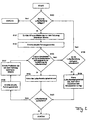
- FIG. 2 shows a flowchart of a method for controlling the air treatment plant 10 of FIG. 1 , The following steps are performed entirely by the controller 14.
- a query is made in step S100 as to whether an air treatment or compressed air delivery should take place by means of an air treatment operation.
- the query of step S100 is, for example, linked to conditions via the compressed air conditions prevailing in individual compressed air circuits coupled to the air treatment plant 10.
- one condition may be the compressed air condition of a compressed air tank associated with a compressed air circuit.
- the compressed air circuits coupled to the air treatment plant may be, in particular, brake circuits, secondary consumer circuits, a trailer supply circuit, a parking brake circuit, a pneumatic suspension circuit, etc.
- step S101 the controller 14 acquires altitude profile data of a route traveled by the vehicle. Since no destination has been specified in the navigation system 12, the navigation system 12 transmits to the control device 14 current or up to a predetermined extent precalculated height profile data of the distance ahead of the vehicle.
- the altitude profile data of the route traveled by the vehicle includes the route profile data from the current position of the vehicle to a predetermined position.
- the distance ahead of the vehicle is predetermined by the length of the road in which the vehicle is currently located.
- the predetermined position is freely definable and may be arbitrarily predetermined between the current position of the vehicle and the end of the road.
- the control device 14 From the altitude profile data of the distance traveled by the vehicle, the control device 14 then calculates inclines and gradients at the current position of the vehicle and / or the course of the route up to the predetermined position.
- current vehicle parameters are determined in step S102.
- the current vehicle parameters comprise at least one element of position and height data of the vehicle obtained from the navigation system 12, distance data relating to a further vehicle ahead with respect to the vehicle, vehicle speed, in particular wheel speeds and / or yaw rates, vehicle acceleration, which is obtained by a driver assistance system current compressed air level of the brake system, a humidity level of a compressed air cartridge of the brake system, an engine speed, an engine torque, clutch and / or gait data of the vehicle and retarder data of the vehicle, etc.
- step S102 the method proceeds to step S103.
- step S103 on the one hand, a query is made as to whether a coasting operation of the vehicle is present.
- the Determining the overrun operation of the vehicle takes place at least partially as a function of one or more of the current vehicle parameters and can additionally take place as a function of the altitude profile data of the route traveled.
- the execution of the air treatment operation can be performed. If the altitude profile data is precalculated from the current position to the predetermined position, then the assessment can also take place taking into account the distance ahead of the vehicle, for example based on the length of the gradient. If the length of the slope is large enough, the execution of the air treatment operation is particularly favored.
- step S104 in which the air conditioning operation is performed.
- the compressor 18 is operated for compressed air delivery or compressed air procurement to the corresponding compressed air circuits.
- step S105 it is judged whether the air processing of step S104 was sufficient. For example, this assessment is based on a review of the compressed air level of the air tank of the corresponding compressed air circuits. If the air treatment was sufficient, the procedure ends and starts all over again.
- step S106 the current vehicle parameters and the altitude profile data of the traveled route are again determined in steps S106 and S107, similarly to the steps S101 and S102. This is due to the fact that changes in the corresponding data may have arisen since the position of the vehicle has since changed may have. Subsequently, the above-mentioned query is made again in step S103. If it is decided in step S103 that there is no coasting operation of the vehicle or the route altitude profile is unsuitable for performing the air conditioning operation, the process proceeds to step S109. There is a further query whether the air conditioning is mandatory.
- step S105 This may for example be the case when at least one compressed air level of a compressed air tank of a corresponding compressed air circuit has fallen below a critical level. If this is the case, even if there is currently no overrun operation of the vehicle or due to inappropriate track height profile, the air treatment operation is performed. Subsequently, the above-explained query of step S105 takes place again. However, if it is determined in step S109 that air conditioning is not necessarily required, for example, the compressed air level is above the critical level, the process returns to step S100 described above.
- FIG. 12 shows a flowchart of a method for controlling the air treatment plant 10.
- the method starts at step S201 with the determination of a destination that has been entered into the navigation system 12 and transmitted to the control device 14.
- step S202 the control device 14 acquires the total distance traveled by the vehicle and to be covered by the navigation system 12, which results from the current start position and the destination of the vehicle.
- step S203 the navigation system 12 transmits a total line height profile of the total distance to be returned to the controller 14. From this, the controller 14 then predicts, in step S204, sections of the total distance where coasting of the vehicle might occur and which would be suitable for performing an air conditioning operation.
- step S205 the current location of the vehicle is obtained.
- step S206 an inquiry is made as to whether the vehicle has arrived at a calculated portion where a coasting operation would be possible and whether air conditioning should be performed.
- the polling of the execution of the air conditioning depends on the same criteria as in step S100 of FIG. 2 , If the vehicle has not arrived at the precalculated section or if no air conditioning is to be performed, the process returns to step S205 until both conditions retrieved in step S206 are met.
- a query according to steps S109 and S108 has been omitted for the sake of simplicity. However, in any case, an air conditioning operation is performed if necessary, as described above in connection with steps S109 and S108.
- step S207 in which the current vehicle parameters analogous to step S102 of FIG. 2 be determined.
- step S208 is executed in which, in the same manner as in step S103 of FIG. 2 is queried whether a coasting operation is present and is preferably verified once again, whether the route height profile for the implementation of the air treatment operation is suitable. If this is not the case, the procedure ends and starts from the beginning, if necessary. If it is determined in step S208 that the coasting operation of the vehicle and the suitability of the route height profile are present, the process proceeds to step S209. There, a probable duration of the overrun operation is determined on the basis of the current vehicle parameters.
- step S210 is executed, in which it is queried whether the duration is sufficient for carrying out the air-conditioning operation is.
- the calculated prospective duration is compared with a predetermined limit value, which indicates a minimum duration of the overrun operation and can be defined as desired. If the expected duration is not sufficient, the procedure ends and starts from the beginning if necessary. If the duration is sufficient, the air conditioning operation is carried out in step S211 and then the current location of the vehicle is determined.
- the distance to a vehicle in front can also be checked in step S210 and it can be judged analogously to the assessment of the anticipated duration of the overrun operation on the basis of the distance data as to whether air conditioning should be carried out.
- step S212 it is queried whether the end of the total distance, that is to say the destination, has been reached. If this is not the case, the method returns to step S206 and remains in the interrogation loop S206 and S205 until the next precalculated section is reached at which a coasting operation would be possible. If it is determined in step S212 that the end of the total distance has been reached, the method ends and optionally restarts from the beginning.
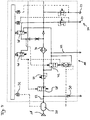
- FIG. 4 shows a system according to the invention with a more detailed representation of the air treatment plant 10 according to a first embodiment of the invention.
- the system comprises the air treatment plant 10 (EAC) of a commercial vehicle, which is preceded by a compressed air reservoir 20 via a main line 22.
- the main line 22 via the air treatment system 10 to one or more compressed air consumers 24, which are connected to corresponding compressed air connections of the air treatment plant 10.
- the compressed air consumers 24 connected to the compressed air connections of the air treatment system 10 can each have compressed air consumption memories assigned to them, For example, brake air reservoir, include.
- a compressor 18 is connected upstream of this.
- the air treatment system 10 comprises a pressure relief valve 10 downstream of the compressed air reservoir 20 and disposed in the main line 22.
- the shut-off valve 28 forms a 2/2-way valve, the for interrupting a compressed air flow to the compressed air consumers 24 is used.
- the safety valve 30 is in the case shown a spring-biased check valve, which is biased towards the compressed air reservoir 20 by a spring and closes. In the opposite direction, overcoming the bias of the spring, the check valve can be opened.
- a pressure sensor 32 is provided in the air treatment system 10, which is coupled to the compressed air reservoir 20 and to a control device (ECU) of the air treatment system 10 of no interest.
- the air treatment system 10 comprises a pressure limiter valve 26 downstream air dryer and air filter unit 36, which is used for compressed air drying and compressed air filtration of the compressed air from the compressor 18 and / or the compressed air storage 20.
- a first and second 2/2-way valve 38, 40 and a drain valve 42 are provided.
- the air treatment system 10 includes other known in the art components, such as the aforementioned control device for controlling the air treatment operation, pressure control valves to regulate the pressures in different pressure circuits of the compressed air consumer 24, the individual pressure circuits associated overflow valves for circuit protection, etc.
- the compressed air reservoir 20 is filled by the compressed air delivery of the compressor 18.
- the check valve 28 is opened.
- the filling operation of the compressor 18 takes place during the coasting operation of the vehicle, as described above.
- the compressed air reservoir 20 is filled to a pressure level that is above a working pressure of the brake system.
- the pressure limiting valve 26 sets the pressure of the compressed air down to the pressure required for the operation of the air treatment system 10.
- the check valve 28 is operated when the vehicle is turned off and the engine is turned off. It secures the pressure in the compressed air reservoir 20 during the downtime of the engine of the vehicle.
- the compressed air reservoir 20 is preferably to be arranged so that any accumulating condensate can flow out of the compressed air reservoir 20 in the direction of the air treatment system 10. The condensed water can then be discharged via the drain valve 42.
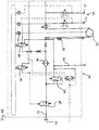
- FIG. 5 shows a second embodiment of the system according to the invention.
- the embodiment of FIG. 5 differs among others from that of FIG. 4 in that the compressed air reservoir 20, the pressure relief valve 26 is connected immediately downstream. Furthermore, the check valve 28 is connected directly downstream of the pressure relief valve 26.
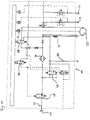
- FIG. 6 shows a third embodiment of the system according to the invention.
- This embodiment differs from the first and second embodiments in that the check valve 28 is omitted.
- the compressed air reservoir 20 is preceded by a check valve which closes in the direction of the compressor 18 and opens in the direction of the compressed air reservoir 20.
- the first 2/2-way valve 38 for controlling the drain valve 42 and the second 2/2-way valve 40 for controlling the ESS line for compressor shutdown via the shuttle valve are provided.
- FIGS. 7 and 8th show a fourth and fifth embodiment of the system according to the invention. Analogous to the FIGS. 4 and 5 are in the FIGS. 7 and 8th each of the pressure relief valve 26 and the check valve 28 in the main line between the compressed air reservoir 20 and the air dryer and air filter unit 36 is provided.
- the pressure relief valve 26 is connected downstream of the compressed air reservoir 20, while the check valve 28 is connected downstream of the pressure limiting valve 26.
- the check valve 28 and the pressure relief valve 26 are arranged in reverse order. Otherwise, the fourth and fifth embodiments are similar to the third embodiment.
- FIG. 9 shows a sixth embodiment of the system according to the invention.
- the compressed air reservoir 20 downstream of the air dryer and air filter unit 36 downstream of the air dryer and air filter unit 36.
- the pressure limiting valve 26 is provided immediately downstream of the compressed air reservoir 20 in the main line 22, before branches to the compressed air consumers 24 depart from the main line 22.
- the safety valve 30 in the vent line the compressed air reservoir 20 immediately upstream and the air dryer and air filter unit 36 downstream, the vent line with the safety valve 30 is connected upstream in the direction of Lucastrockner- and air filter unit 36 check valve.
- the compressed air reservoir 20 in this embodiment is an internal volume in the air treatment unit or air treatment plant 10. Otherwise, this embodiment corresponds to the in FIG. 7 or 8th shown embodiment.
- FIG. 10 shows a seventh embodiment of the system according to the invention.
- the inventive system of the seventh embodiment differs from that of FIG. 9
- the compressed air tank 20 is outsourced from the air treatment plant 10, that forms an external compressed air reservoir 20.
- the compressed air consumers 24, in particular of the brake system 34 via the first 2/2-way valve 38 for regeneration control (regeneration valve) with the air dryer and air filter unit 36 are connected.
- regeneration control regeneration valve
- the air dryer and air filter unit 36 to clean the regeneration air of the brake system 34.
- This regeneration air is passed through the air dryer and air filter unit 36, which is then loaded with moisture and foreign particles from the filter unit is discharged via the drain valve 42 and the vent 44 into the atmosphere.
- FIG. 11 shows an eighth embodiment of the system according to the invention.
- This embodiment differs from the seventh embodiment in that in this case the compressed air reservoir 20 is coupled to the first solenoid valve 38 for regeneration control, whereby the regeneration air for the air dryer and air filter unit 36 can be supplied from the compressed air reservoir 20.
Landscapes
- Engineering & Computer Science (AREA)
- Mechanical Engineering (AREA)
- Transportation (AREA)
- Chemical & Material Sciences (AREA)
- Analytical Chemistry (AREA)
- Physics & Mathematics (AREA)
- Fluid Mechanics (AREA)
- General Engineering & Computer Science (AREA)
- Valves And Accessory Devices For Braking Systems (AREA)
Description
Die Erfindung betrifft ein System mit einer Luftaufbereitungsanlage, insbesondere der eines Nutzfahrzeugs.The invention relates to a system with an air treatment plant, in particular that of a commercial vehicle.
Weiterhin betrifft die Erfindung ein Verfahren zur Steuerung einer Luftaufbereitungsanlage eines Fahrzeugs, insbesondere der eines Nutzfahrzeugs.Furthermore, the invention relates to a method for controlling an air conditioning system of a vehicle, in particular of a commercial vehicle.
Derartige Systeme/Verfahren sind beispielsweise aus den Entgegenhaltungen
Allgemein werden in Nutzfahrzeugen Systeme mit Luftaufbereitungsanlagen eingesetzt, insbesondere elektronische Luftaufbereitungsanlagen, die die Versorgung von Druckluftverbraucherkreisen mit Druckluft über Steuereinrichtungen steuern. Derartige Druckluftverbraucherkreise sind beispielsweise Bremskreise eines Nutzfahrzeugsbremssystems, ein Nebenverbraucherkreis, ein Anhängerversorgungskreis, ein Feststellbremsanlagenkreis, ein Luftfederungskreis etc. Daher ist die Druckluftversorgung beziehungsweise die Luftaufbereitung eine zentrale Komponente im Nutzfahrzeugbremssystem. Insbesondere für das Nutzfahrzeugbremssystem steuert die Luftaufbereitungsanlage die Aufnahme von Bremsenergie in der Form von komprimierter Luft. Damit ist sie ein Zwischenstück beziehungsweise Bindeglied zwischen einem zur Druckluftbeschaffung beziehungsweise Druckluftversorgung vorgesehenen Kompressor, der öl- und wasserhaltige Luft fördert, und den Druckluftverbraucherkreisen im Nutzfahrzeug.Generally in commercial vehicles systems with air treatment systems are used, in particular electronic air treatment systems that control the supply of compressed air consumer circuits with compressed air via control devices. Such compressed air consumer circuits are, for example, brake circuits of a commercial vehicle brake system, a secondary consumer circuit, a trailer supply circuit, a parking brake system circuit, a pneumatic suspension circuit, etc. Therefore, the compressed air supply or the air treatment is a key component in the commercial vehicle brake system. In particular, for the commercial vehicle braking system, the air handling system controls the absorption of braking energy in the form of compressed air. Thus, it is an intermediate piece or link between a provided for compressed air procurement or compressed air supply compressor that promotes oil and water-containing air, and the compressed air consumer circuits in the commercial vehicle.
Elektronisch gesteuerte Luftaufbereitungsanlagen sind bereits im Stand der Technik bekannt. Eine derartige Luftaufbereitungsanlage steuert beispielsweise mittels einer ihr zugeordneten elektronischen Steuereinrichtung die Aufnahme von Druckluft, deren Filterung und Trocknung, sowie die Verteilung der so gereinigten Druckluft auf die verschiedenen Druckluftverbraucherkreise. Dies erfolgt im Allgemeinen in Verbindung mit bestimmten Kompressoren unterschiedlicher Bauart und weiterhin unter Verwendung von Fahrzeuginformationen aus anderen im Nutzfahrzeug vorgesehenen Steuergeräten. Jedoch führt die Luftaufbereitung durch die Luftaufbereitungsanlage zu einem hohen Energie- beziehungsweise Kraftstoffverbrauch. Dies rührt daher, dass für die Druckluftbeschaffung beziehungsweise die Bereitstellung der Druckluft der Kompressor beispielsweise über eine kraftschlüssige Verbindung durch einen Verbrennungsmotor des Nutzfahrzeugs angetrieben werden muss. Im Stand der Technik wurden bereits Maßnahmen zur Reduzierung des Kraftstoffverbrauchs ergriffen, wobei mehrere und teilweise auch unterschiedliche Ansätzen verfolgt werden.Electronically controlled air handling plants are already known in the art. Such an air treatment plant controls, for example, by means of an associated electronic control device recording of compressed air, their filtering and drying, and the distribution of the thus cleaned compressed air to the various compressed air consumer circuits. This is generally done in conjunction with certain compressors of different types, and further using vehicle information from other controllers provided in the commercial vehicle. However, the air treatment through the air treatment plant leads to a high energy and fuel consumption. This is due to the fact that for the supply of compressed air or the provision of compressed air, the compressor must be driven for example via a non-positive connection by an internal combustion engine of the commercial vehicle. In the prior art measures have already been taken to reduce fuel consumption, with several and sometimes different approaches are pursued.
Ein Ansatz ist beispielsweise eine Umschaltung eines Kompressorwiderstands auf einen Leerlaufbetrieb, bei dem lediglich die für den Leerlauf erforderliche Antriebsleistung für den Verbrennungsmotor anfällt. Diese Umschaltung erfolgt üblicherweise bei Fahrtzuständen des Nutzfahrzeugs, bei denen beispielsweise das Bremssystem mit Druckluft gefüllt ist und keine weitere Druckluftförderung notwendig ist. Daher verfügen die für die Umschaltung tauglichen Kompressoren über eine pneumatische Steuerleitung, die so genannte ESS-Leitung. Über die Steuerleitung werden diese Kompressoren durch die Luftaufbereitungsanlage angesteuert, wodurch die Förderung der Druckluft gegen die in den Druckluftverbraucherkreisen vorliegenden Druckluftniveaus unterbrochen wird. Der Kompressor pumpt in diesem Leerlaufbetrieb beispielsweise die Luft im Kreis und/oder tauscht sie mit der Umgebung aus. Ein weiterer Ansatz besteht darin, die kraftschlüssige Verbindung zwischen dem Verbrennungsmotor und dem Kompressor während des Leerlaufbetriebs vollständig zu unterbrechen, wenn eine Luftaufbereitung nicht erforderlich ist. Dies kann beispielsweise durch eine Kompressorkupplung beziehungsweise eine zwischen dem Kompressor und Verbrennungsmotor vorgesehene Kupplung umgesetzt werden. Im Vergleich zum vorgenannten Ansatz wird in diesem Fall die Leerlauflast während des Leerlaufbetriebs des Kompressors gänzlich dem Verbrennungsmotor abgenommen. Weiterhin ist im Stand der Technik ein Ansatz bekannt, eine Synchronisierung eines Luftaufbereitungsbetriebs beziehungsweise die Druckluftbeschaffung mit Schubbetrieben beziehungsweise Schubphasen des Verbrennungsmotors vorzunehmen, d.h. den Kompressor in den Schubbetrieben des Verbrennungsmotors anzutreiben. In diesem Zusammenhang werden unter Schubbetrieben des Nutzfahrzeugs die Betriebsphasen verstanden, in denen der Motor bei kraftschlüssig verbundenem Antriebsstrang durch die kinetische Energie des Fahrzeugs ohne Kraftstoffverbrauch geschleppt wird, beispielsweise in einem Motorbremsbetrieb. Insbesondere wird der Schubbetrieb des Nutzfahrzeugs bei den dem Stand der Technik angehörenden Luftaufbereitungsanlagen dadurch ermittelt, dass verschiedene, durch einen in dem Nutzfahrzeug üblicherweise verwendeten CAN-Bus zur Verfügung gestellte Informationen, wie beispielsweise ein negatives Motordrehmoment bei gleichzeitig eingelegtem Gang und nicht getrennter beziehungsweise kraftübertragender Kupplung, verwendet werden. Dabei wird bei derartigen elektronischen Luftaufbereitungsanlagen bei einer bestimmten Dauer dieses Zustands von mehreren Sekunden auf eine Gefällestrecke und damit einen längeren Erhalt des Schubbetriebs geschlossen. Somit wird der Schubbetrieb dazu verwendet, die Druckluftbeschaffung durchzuführen und damit eine Erhöhung des Druckluftniveaus in beispielsweise der Bremsanlage ohne Kraftstoffverbrauch (Overrun-Mode) zu bewirken. Bei einer Umschaltung des Kompressors von der Druckluftbeschaffung auf den Leerlaufbetrieb kann jedoch, abhängig von der Ausführung der Luftaufbereitu8ngsalage, ein nicht zu vernachlässigendes Druckluftvolumen, beispielsweise aus Leitungen etc., verloren geht. Insbesondere wird dieses Druckluftvolumen bei der Umschaltung in die Umgebung abgeblasen. Daher sollte die Umschaltung nur dann erfolgen, wenn ein Schubbetrieb voraussichtlich länger anhält. Dies wird jedoch bei der Durchführung des Luftaufbereitungsbetriebs gemäß dem Stand der Technik nicht berücksichtig; es wird lediglich das Vorliegen des Schubbetriebs ermittelt. Dadurch wird bei unter Umständen nur sehr kurzen Schubphasen des Verbrennungsmotors auf die verbrauchsfreie Luftförderung beziehungsweise Luftaufbereitung umgeschaltet. Dabei kann insbesondere beim anschließenden Umschalten beispielsweise zum Leerlaufbetrieb des Kompressors eine Druckluftmenge ausgestoßen werden, die gleich oder sogar größere als die zuvor geförderte Druckluftmenge ist. Somit geht anstelle einer ursprünglich beabsichtigten Energieeinsparung Energie verloren. Ursache hierfür ist bei der derzeitigen Ermittlung des Schubbetriebs eine fehlende Sicherheit über den Fortbestand des Schubbetriebs. Zudem wirkt sich ein häufiger Wechsel zwischen den beiden Betrieben der Druckluftförderung und des Leerlaufs nachteilig auf die erreichbare Lebensdauer von entsprechenden schaltenden Komponenten aus. Aus den vorstehend genannten Gründen kann somit unter Umständen der Fall auftreten, dass der Kraftstoffverbrauch sogar erhöht wird. Seitens der Autohersteller besteht jedoch zunehmend die Kundenforderung nach Verbesserung der Funktionalität bei allen Energie und damit Kraftstoff verbrauchenden Komponenten.One approach is, for example, a switchover of a compressor resistance to an idling operation, in which only the necessary for idling drive power for the internal combustion engine is obtained. This switching usually takes place during driving conditions of the commercial vehicle in which, for example, the brake system is filled with compressed air and no further compressed air delivery is necessary. Therefore, the compressors that are suitable for switching have a pneumatic control line, the so-called ESS cable. About the control line, these compressors are controlled by the air treatment plant, whereby the promotion of compressed air is interrupted against the present in the compressed air consumer circuits compressed air levels. For example, in this idle mode, the compressor circulates air in the circuit and / or exchanges it with the environment. Another approach is to completely break the positive connection between the engine and the compressor during idle operation when air conditioning is not required. This can be implemented, for example, by a compressor clutch or a clutch provided between the compressor and internal combustion engine. Compared to the above approach, in this case, the idling load during the idle operation of the compressor is completely removed from the engine. Furthermore, in the prior art, an approach is known to perform a synchronization of an air treatment operation or the compressed air procurement with pushing operations or coasting phases of the internal combustion engine, ie to drive the compressor in the pushing operations of the internal combustion engine. In this context, under pushing operations of the commercial vehicle, the operating phases are understood in which the engine is towed by the kinetic energy of the vehicle without fuel consumption in force-connected drive train, for example in an engine braking operation. In particular, the overrun operation of the commercial vehicle in the prior art air conditioning systems is determined by various information provided by a CAN bus commonly used in the commercial vehicle, such as a negative engine torque with gear engaged simultaneously and not separate or force transmitting clutch , be used. In this case, in such electronic air treatment plants at a certain duration of this condition of several seconds on a downgrade and thus a longer receipt of the overrun operation closed. Thus, the overrun operation is used to perform the compressed air procurement and thus to cause an increase in the compressed air level in, for example, the brake system without fuel consumption (overrun mode). When switching the compressor from the compressed air procurement to idle operation, however, depending on the design of the air conditioning system, a non-negligible compressed air volume, for example, from lines, etc., get lost. In particular, this compressed air volume is blown off when switching to the environment. Therefore, switching should only take place when an overrun is expected to last longer. However, this is not taken into consideration when carrying out the air treatment operation according to the prior art; only the presence of overrun operation is determined. As a result, in some circumstances only very short overrun phases of the internal combustion engine are switched to the consumption-free air conveying or air conditioning. In this case, in particular during the subsequent switching, for example, to the idling operation of the compressor, a compressed air amount can be ejected, which is equal to or even larger than the previously promoted amount of compressed air. Thus, energy is lost instead of an originally intended energy saving. The reason for this is in the current determination of the push operation, a lack of security on the continued existence of the push operation. In addition, a frequent change between the two companies of compressed air delivery and idling adversely affects the achievable life of corresponding switching components. For the reasons mentioned above, it may therefore be the case that fuel consumption is even increased. On the part of the automaker, however, there is an increasing demand from customers for improving the functionality of all energy and thus fuel-consuming components.
Ein weiterer Nachteil besteht darin, dass bei der Synchronisierung des Schubbetriebs mit dem Luftaufbereitungsbetrieb lediglich recht wenig Energie beziehungsweise Druckluft gewonnen werden kann. Grund hierfür ist, dass das Druckluftniveau beispielsweise aufgrund der Auslegung des Systems mit der Luftaufbereitungsanlage nur recht wenig über das Betriebsdruckniveau der Bremsanlage angehoben wird und als Energiespeicher nur die vorhandenen Volumina, beispielsweise Leitungsvolumina, im Bremssystem genutzt werden.Another disadvantage is that in the synchronization of the overrun operation with the air treatment operation only a little energy or compressed air can be obtained. The reason for this is that the compressed air level, for example, due to the design of the system with the air treatment system is only slightly raised above the operating pressure level of the brake system and as energy storage only the existing volumes, such as line volumes, are used in the brake system.
Es ist daher die Aufgabe der Erfindung, die gattungsgemäßen Systeme mit Luftaufbereitungsanlagen und die gattungsgemäßen Verfahren zur Steuerung von Luftaufbereitungsanlagen derart weiterzubilden, dass der Kraftstoffverbrauch eines Fahrzeugs weiter reduziert wird.It is therefore an object of the invention to further develop the generic systems with air treatment systems and the generic method for controlling air treatment plants such that the fuel consumption of a vehicle is further reduced.
Diese Aufgabe wird durch die Merkmale der unabhängigen Ansprüche gelöst.This object is solved by the features of the independent claims.
Vorteilhafte Ausgestaltungen und Weiterbildungen der Erfindung ergeben sich aus den abhängigen Ansprüchen.Advantageous embodiments and modifications of the invention will become apparent from the dependent claims.
Das erfindungsgemäße System baut auf dem gattungsgemäßen Stand der Technik dadurch auf, dass stromaufwärts von zumindest einem zu einem Druckluftverbraucher führenden Druckluftanschluss der Luftaufbereitungsanlage ein Druckluftspeicher vorgesehen ist der einer Lufttrocknereinheit der Luftaufbereitungsanlage vorgeschaltet ist. Der Energiespeicher beziehungsweise Druckluftspeicher kann beispielsweise durch ein Volumen ausgebildet werden, das als Leitung oder als Behälter ausgeführt ist. Durch die Verwendung des zusätzlichen Energiespeichers beziehungsweise Druckluftspeichers kann die Druckluftaufnahme deutlich erhöht werden. Insbesondere im Zusammenhang mit der Synchronisierung des Schubbetriebs mit dem Luftaufbereitungsbetrieb kann durch diese Weiterbildung mehr Druckluft aufgenommen werden. Während der Zeit beziehungsweise der Phasen, bei denen das Bremssystem aus dem Energiespeicher versorgt werden kann, wird der Kompressor abgeschaltet, um Kraftstoff zu sparen. Dadurch kann das Bremssystem nach der Synchronisierung des Schubbetriebs mit dem Luftaufbereitungsbetrieb des Nutzfahrzeugs dann für längere Zeit aus dem Druckluftspeicher versorgt werden. Der Kompressor wird daher abgeschaltet, um Kraftstoff zu sparen. Somit kann insgesamt die Anzahl der Antriebsphasen des Kompressors verringert werden. Erst wenn der Druckluftspeicherdruck auf beispielsweise das Betriebsdruckniveau des Bremssystems wieder abgefallen ist und keine Schubbetriebsphase zum Füllen genutzt werden kann, wird mit dem vom Verbrennungsmotor des Nutzfahrzeugs angetriebenen Kompressor Druckluft nachgefördert.The inventive system is based on the generic state of the art in that upstream of at least one leading to a compressed air consumer compressed air connection of the air treatment system, a compressed air reservoir is provided which is connected upstream of an air dryer unit of the air treatment plant. The energy storage or compressed air storage can be formed for example by a volume that is designed as a line or as a container. By using the additional energy storage or compressed air storage, the compressed air intake can be significantly increased. In particular, in connection with the synchronization of the push operation with the air treatment operation can be absorbed by this training more compressed air. During the time or phases in which the brake system can be supplied from the energy storage, the compressor is turned off to save fuel. Thus, the brake system after the synchronization of the overrun operation with the air conditioning operation of the commercial vehicle then for be supplied for a long time from the compressed air reservoir. The compressor is therefore turned off to save fuel. Thus, the total number of drive phases of the compressor can be reduced. Only when the compressed air storage pressure has dropped to, for example, the operating pressure level of the brake system again and no overrun operating phase can be used for filling compressed air is nachgefördert with the driven by the engine of the commercial vehicle compressor.
Das erfindungsgemäße System kann in vorteilhafter Weise derart weitergebildet sein, dass dem Druckluftspeicher ein der Luftaufbereitungsanlage zugeordnetes Druckbegrenzungsventil nachgeschaltet ist. Der vorgeschaltete Druckluftspeicher kann somit mit einem höheren Druck als der Betriebsdruck des Bremssystems betrieben werden. Mit dem dem Druckluftspeicher nachgeschalteten Druckbegrenzungsventil soll der Druck der Druckluft bei Druckluftförderung des Druckluftspeichers auf das übliche Druckniveau reduziert werden, so dass Komponenten des Bremssystems normal betrieben werden können.The system according to the invention can be developed in an advantageous manner such that the compressed air accumulator is connected downstream of a pressure-limiting valve assigned to the air-conditioning system. The upstream compressed air reservoir can thus be operated at a higher pressure than the operating pressure of the brake system. With the pressure relief valve downstream of the pressure relief valve, the pressure of the compressed air in compressed air delivery of the compressed air reservoir is to be reduced to the usual pressure level, so that components of the brake system can be operated normally.
Bei der Anordnung des Druckluftspeichers vor der Lufttrocknereinheit, insbesondere der Lufttrockner- und Luftfiltereinheit, wird das erfindungsgemäße System so ausgebildet, dass dem Druckbegrenzungsventil ein Sperrventil unmittelbar vor- oder nachgeschaltet ist. Dadurch kann beim Abstellen des Fahrzeugs der Druck in dem Druckluftspeicher gesichert werden. Somit muss der Druckluftspeicher bei einem erneuten Starten beziehungsweise Anlassen des Fahrzeuges nicht neu befüllt werden.In the arrangement of the compressed air reservoir in front of the air dryer unit, in particular the air dryer and air filter unit, the system according to the invention is designed so that the pressure relief valve, a check valve is directly upstream or downstream. As a result, the pressure in the compressed air reservoir can be secured when the vehicle is parked. Thus, the compressed air reservoir does not have to be refilled when restarting or starting the vehicle.
Darüber hinaus kann vorgesehen sein, das erfindungsgemäße System so zu verwirklichen, dass der Druckluftspeicher der Luftaufbereitungsanlage vorgeschaltet ist.In addition, it can be provided to realize the system according to the invention so that the compressed air reservoir of the air treatment plant is connected upstream.
Weiterhin ist es besonders vorteilhaft, wenn das erfindungsgemäße System derart ausgeführt ist, dass ein der Luftaufbereitungsanlage zugeordnetes Sicherheitsventil dem Druckluftspeicher vor- oder nachgeschaltet und dem Druckluftbegrenzungsventil sowie dem Sperrventil vorgeschaltet ist. Dadurch wird ein unangemessen hoher Druck durch das Sicherheitsventil aus dem Druckluftspeicher abgelassen, wodurch der Druckluftspeicher gegen eine Drucküberschreitung abgesichert ist.Furthermore, it is particularly advantageous if the system according to the invention is designed in such a way that a safety valve assigned to the air treatment system is connected upstream or downstream of the compressed air reservoir and upstream of the compressed air limiting valve and the shutoff valve. As a result, an unreasonably high pressure is discharged through the safety valve from the compressed air reservoir, whereby the compressed air reservoir is protected against overpressure.
Bevorzugt wird das erfindungsgemäße System so verwirklicht, dass das Sicherheitsventil ein federvorgespanntes Rückschlagventil umfasst, das in Richtung zum Druckluftspeicher vorgespannt wird und schließt, und das in umgekehrter Richtung unter Überwindung der Vorspannung öffnet.Preferably, the inventive system is realized so that the safety valve comprises a spring-biased check valve, which is biased towards the compressed air reservoir and closes, and opens in the opposite direction, overcoming the bias.
Darüber hinaus kann das erfindungsgemäße System derart realisiert werden, dass der Druckluftspeicher mit einer Hauptleitung gekoppelt ist, die über die Luftaufbereitungsanlage zu einem oder mehreren Druckluftverbrauchern führt.In addition, the system according to the invention can be realized such that the compressed air reservoir is coupled to a main line, which leads via the air treatment plant to one or more compressed air consumers.
Vorzugsweise wird das erfindungsgemäße System so ausgebildet, dass dem Druckluftspeicher eine Druckmittelquelle, insbesondere ein Kompressor, vorgeschaltet ist.Preferably, the system according to the invention is designed so that the compressed air reservoir is preceded by a pressure medium source, in particular a compressor.
Weiterhin kann das erfindungsgemäße System so weitergebildet sein, dass ein der Luftaufbereitungsanlage zugeordneter Drucksensor vorgesehen ist, der den Druck in dem Druckluftspeicher erfasst. Dabei kann der Drucksensor insbesondere zur Drucküberwachung des Druckluftspeichers dienen, um Rückschlüsse über den Füllstand des Druckluftspeichers zu erhalten.Furthermore, the system according to the invention can be developed such that a pressure sensor assigned to the air treatment system is provided which detects the pressure in the compressed air reservoir. In this case, the pressure sensor can be used in particular for monitoring the pressure of the compressed air reservoir to obtain conclusions about the level of the compressed air reservoir.
In einer bevorzugten Ausführung wird das erfindungsgemäße System so verwirklicht, dass der Druckluftspeicher dazu geeignet ist, in einem Schubbetrieb des Nutzfahrzeugs auf ein Druckniveau aufgefüllt zu werden, das über einem Arbeitsdruck eines Bremssystems liegt. Der Druckluftspeicher ist somit dazu imstande, im Schubbetrieb auf ein definiertes Druckniveau aufgefüllt zu werden, welches über dem Arbeitsdruck des Bremssystems liegt. Wenn der Behälterdruck auf das Betriebsdruckniveau des Bremssystems abgefallen ist, bei dem das Nachfüllen gestartet werden muss, und keine Schubbetriebphase zum Füllen genutzt werden kann, dann wird mit dem vom Motor angetriebenen Kompressor nachgefördert.In a preferred embodiment, the system according to the invention is realized in such a way that the compressed air accumulator is suitable for being filled in a coasting operation of the commercial vehicle to a pressure level which is above a working pressure of a brake system. The compressed air reservoir is thus able to be filled in overrun to a defined pressure level, which is above the working pressure of the brake system. If the tank pressure has dropped to the operating pressure level of the brake system, in which the refilling must be started, and no overrun phase can be used for filling, then is fed with the motor-driven compressor.
Darüber hinaus kann das erfindungsgemäße System auch dergestalt sein, dass die Luftaufbereitungsanlage und der Druckluftspeicher in einem gemeinsamen Gehäuse untergebracht sind. Ebenso ist aber auch denkbar, die Luftaufbereitungsanlage und den Druckluftspeicher in separaten Gehäusen unterzubringen. Weiterhin können das Sperrventil, das Druckbegrenzungsventil, das Sicherheitsventil, Drucksensor und der Druckluftspeicher separat verbaut oder vorzugsweise in das Gehäuse der Luftaufbereitungsanlage beziehungsweise -einheit verbaut werden.In addition, the system according to the invention can also be such that the air treatment system and the compressed air storage are accommodated in a common housing. Likewise, it is also conceivable to accommodate the air treatment plant and the compressed air storage in separate housings. Furthermore, the check valve, the pressure relief valve, the safety valve, pressure sensor and the compressed air reservoir can be installed separately or preferably installed in the housing of the air treatment plant or unit.
Das erfindungsgemäße Verfahren baut auf dem gattungsgemäßen Stand der Technik dadurch auf, dass stromaufwärts von zumindest einem zu einem Druckluftverbraucher führenden Druckluftanschluss der Luftaufbereitungsanlage ein Druckluftspeicher vorgesehen ist, der auf ein Druckluftniveau aufgefüllt wird, das über einem Arbeitsdruck eines Bremssystems liegt, wobei der Druckluftspeicher einer Lufttrockner der Luftaufbereitungsanlage vorgeschaltet ist. Dadurch ergeben sich die im Zusammenhang mit dem erfindungsgemäßen System erläuterten Eigenschaften und Vorteile in gleicher oder ähnlicher Weise, weshalb zur Vermeidung von Wiederholungen auf die entsprechenden Ausführungen im Zusammenhang mit dem erfindungsgemäßen System verwiesen wird. Gleiches gilt sinngemäß für die folgenden bevorzugten Ausführungsformen des erfindungsgemäßen Verfahrens, wobei zur Vermeidung von Wiederholungen auch diesbezüglich auf die entsprechenden Ausführungen im Zusammenhang mit dem erfindungsgemäßen System verwiesen wird.The inventive method is based on the generic state of the art in that upstream of at least one leading to a compressed air consumer compressed air connection of the air treatment system, a compressed air reservoir is provided, which is filled to a compressed air level, which is above a working pressure of a brake system, wherein the compressed air reservoir of an air dryer of the air treatment plant is connected upstream. As a result, the properties and advantages explained in connection with the system according to the invention result in the same or a similar manner, for which reason reference is made to the corresponding statements in connection with the system according to the invention in order to avoid repetition. The same applies mutatis mutandis to the following preferred embodiments of the method according to the invention, reference being made to avoid repetition in this regard to the corresponding statements in connection with the system according to the invention.
Das erfindungsgemäße Verfahren kann in vorteilhafterweise so ausgeführt werden, dass der Druckluftspeicher bei einem Schubbetrieb des Fahrzeugs aufgefüllt wird.The inventive method can be advantageously carried out so that the compressed air reservoir is filled during a coasting operation of the vehicle.
Weiterhin kann das erfindungsgemäße Verfahren derart weitergebildet werden, dass ein Kompressor angetrieben wird, um Druckluft zu dem Bremssystem nachzufördern, wenn das Druckluftniveau in dem Druckluftspeicher auf oder unter den Arbeitsdruck des Bremssystems gefallen ist.Furthermore, the inventive method can be developed such that a compressor is driven to nachzufördern compressed air to the brake system when the compressed air level has fallen in the compressed air reservoir at or below the working pressure of the brake system.
Darüber hinaus kann das erfindungsgemäße Verfahren auch so verwirklicht werden, dass ein dem Druckluftspeicher nachgeschaltetes Sperrventil in eine Schließstellung gebracht wird, wenn das Fahrzeug abgestellt wird.In addition, the method according to the invention can also be realized in such a way that a check valve connected downstream of the compressed air store is brought into a closed position when the vehicle is parked.
Die Erfindung wirkt besonders vorteilhaft, wenn die Schubphasen, in denen der Behälter ohne Einsatz von Kraftstoff nachgefüllt werden kann, möglichst vollständig ausgenutzt werden. Die Kenntnis der Topologie der Fahrtstrecke durch GPS-Informationen kann zur möglichst vollständigen Ausnutzung der Schubphasen beitragen.The invention is particularly advantageous if the over-travel phases in which the container can be topped up without the use of fuel are utilized as completely as possible. Knowledge of the topology of the route through GPS information can contribute to the fullest possible utilization of the shear phases.
Bevorzugte Ausführungsbeispiele der Erfindung werden nachstehend anhand der Figuren beispielhaft erläutert.Preferred embodiments of the invention are explained below by way of example with reference to FIGS.
Es zeigen:
Figur 1- eine schematische Darstellung einer Luftaufbereitungsanlage eines Fahrzeugs, die zur Durchführung der Verfahren nach den
Figuren 2 und3 geeignet ist; - Figur 2
- ein Flussdiagramm eines Verfahrens zur Steuerung einer Luftaufbereitungsanlage;
Figur 3- ein Flussdiagramm eines weiteren Verfahrens zur Steuerung einer Luftaufbereitungsanlage;
- Figur 4
- ein erfindungsgemäßes System mit einer ausführlicheren Darstellung der Luftaufbereitungsanlage gemäß einem ersten Ausführungsbeispiel der Erfindung;
- Figur 5
- das erfindungsgemäße System gemäß einem zweiten Ausführungsbeispiel der Erfindung;
- Figur 6
- das erfindungsgemäße System gemäß einem dritten Ausführungsbeispiel der Erfindung;
Figur 7- das erfindungsgemäße System gemäß einem vierten Ausführungsbeispiel der Erfindung;
- Figur 8
- das erfindungsgemäße System gemäß einem fünften Ausführungsbeispiel der Erfindung;
- Figur 9
- das erfindungsgemäße System gemäß einem sechsten Ausführungsbeispiel der Erfindung;
Figur 10- das erfindungsgemäße System gemäß einem siebten Ausführungsbeispiel der Erfindung; und
- Figur 11
- das erfindungsgemäße System gemäß einem achten Ausführungsbeispiel der Erfindung;
- FIG. 1
- a schematic representation of an air conditioning system of a vehicle, which is used to carry out the method according to
Figures 2 and3 suitable is; - FIG. 2
- a flowchart of a method for controlling an air treatment plant;
- FIG. 3
- a flowchart of another method for controlling an air treatment plant;
- FIG. 4
- a system according to the invention with a more detailed representation of the air treatment plant according to a first embodiment of the invention;
- FIG. 5
- the inventive system according to a second embodiment of the invention;
- FIG. 6
- the inventive system according to a third embodiment of the invention;
- FIG. 7
- the system according to the invention according to a fourth embodiment of the invention;
- FIG. 8
- the inventive system according to a fifth embodiment of the invention;
- FIG. 9
- the inventive system according to a sixth embodiment of the invention;
- FIG. 10
- the inventive system according to a seventh embodiment of the invention; and
- FIG. 11
- the inventive system according to an eighth embodiment of the invention;
In Schritt S205 wird der aktuelle Standort des Fahrzeugs bezogen. Anschließend erfolgt in Schritt S206 eine Abfrage, ob das Fahrzeug bei einem berechneten Abschnitt, bei dem ein Schubbetrieb möglich wäre, angekommen ist, und ob eine Luftaufbereitung ausgeführt werden soll. Dabei hängt die Abfrage der Ausführung der Luftaufbereitung von den gleichen Kriterien ab, wie bei Schritt S100 von
Im Betrieb wird der Druckluftspeicher 20 durch die Druckluftförderung des Kompressors 18 befüllt. Bei diesem Befüllungsvorgang ist das Sperrventil 28 geöffnet. Vorzugsweise findet der Befüllungsvorgang des Kompressors 18 bei dem Schubbetrieb des Fahrzeugs statt, wie vorstehend beschrieben ist. Der Druckluftspeicher 20 wird dabei auf ein Druckniveau aufgefüllt, das über einem Arbeitsdruck des Bremssystems liegt. Das Druckbegrenzungsventil 26 setzt dabei den Druck der Druckluft auf den für den Betrieb der Luftaufbereitungsanlage 10 erforderlichen Druck herab. Das Sperrventil 28 wird betätigt, wenn das Fahrzeug abgestellt und der Motor ausgeschaltet wird. Es sichert den Druck in dem Druckluftspeicher 20 während der Stillstandszeit des Motors des Fahrzeugs. Der Druckluftspeicher 20 ist vorzugsweise so anzuordnen, dass eventuell anfallendes Kondenswasser aus dem Druckluftspeicher 20 in Richtung der Luftaufbereitungsanlage 10 abfließen kann. Das Kondenswasser kann dann über das Ablassventil 42 ausgestoßen werden.In operation, the
- 1010
- LuftaufbereitungsanlageAir handling unit
- 1212
- Navigationssystemnavigation system
- 1414
- Steuereinrichtungcontrol device
- 1616
- Antriebsstrangpowertrain
- 1818
- Kompressorcompressor
- 2020
- DruckluftspeicherCompressed air storage
- 2222
- Hauptleitungmain
- 2424
- DruckluftverbraucherAir consumers
- 2626
- DruckbegrenzungsventilPressure relief valve
- 2828
- Sperrventilcheck valve
- 3030
- Sicherheitsventilsafety valve
- 3232
- Drucksensorpressure sensor
- 3434
- Bremssystembraking system
- 3636
- Lufttrockner- und LuftfiltereinheitAir dryer and air filter unit
- 3838
- erstes 2/2-Wegeventilfirst 2/2-way valve
- 4040
- zweites 2/2-Wegeventilsecond 2/2-way valve
- 4242
- Ablassventildrain valve
- 4444
- Ablassdrainage
Claims (15)
- System with an air conditioning unit (10), in particular that of a commercial vehicle, wherein upstream from at least one compressed air connection of the air conditioning unit (10) that leads to a compressed air consumer (24) a compressed air reservoir (20) is provided, characterised in that the compressed air reservoir (20) is connected upstream from an air dryer unit (36) of the air conditioning unit (10).
- System according to Claim 1, characterised in that downstream from the compressed air reservoir (20) there is connected a pressure-limiting valve (26) associated with the air conditioning unit (10).
- System according to Claim 2, characterised in that a check valve (28) associated with the air conditioning unit (10) is connected immediately upstream or downstream from the pressure-limiting valve (26).
- System according to any of Claims 1 to 3, characterised in that the compressed air reservoir (20) is connected upstream from the air conditioning unit (10).
- System according to any of Claims 1 to 4, characterised in that a safety valve (30) associated with the air conditioning unit (10) is connected upstream or downstream from the compressed air reservoir (20) and from the compressed air limiting valve (26) and the check valve (28).
- System according to Claim 5, characterised in that the safety valve (30) comprises a spring-loaded non-return valve (30), which is pre-stressed and closes in the direction toward the compressed air reservoir (20), and which opens in the reverse direction when the pre-stress is overcome.
- System according to any of Claims 1 to 6, characterised in that the compressed air reservoir (20) is connected to a main line (22), which leads via the air conditioning unit (10) to one or more compressed air consumers (24).
- System according to any of Claims 1 to 7, characterised in that connected upstream from the compressed air reservoir (20) there is a pressure medium source (18), in particular a compressor (18).
- System according to any of Claims 1 to 8, characterised in that a pressure sensor (32) associated with the air conditioning unit (10) is provided, which detects the pressure in the compressed air reservoir (20).
- System according to any of Claims 1 to 9, characterised in that the compressed air reservoir (20) is suitable for being filled during overdrive operation of the commercial vehicle, up to a pressure level higher than a working pressure of a brake system (34).
- System according to any of Claims 1 to 10, characterised in that the air conditioning unit (10) and the compressed air reservoir (20) are accommodated in a common housing.
- Method for controlling an air conditioning unit (10) of a vehicle, in particular that of a commercial vehicle, characterised in that upstream from at least one compressed air connection of the air conditioning unit (10) that leads to a compressed air consumer (24), a compressed air reservoir (20) is provided, which is filled to a compressed air level higher than a working pressure of a brake system (34), and the compressed air reservoir (20) is connected upstream from an air dryer unit (36) of the air conditioning unit (10).
- Method according to Claim 12, characterised in that the compressed air reservoir (20) is filled during overdrive operation of the vehicle.
- Method according to Claims 12 or 13, characterised in that a compressor (18) is driven in order to top up the brake system (34) with compressed air if the pressure level in the compressed air reservoir (20) has fallen to the working pressure of the braking system (34) or below it.
- Method according to any of Claims 12 to 14, characterised in that a check valve (28) connected downstream from the compressed air reservoir (20) is brought to a closed position when the vehicle is parked.
Applications Claiming Priority (1)
| Application Number | Priority Date | Filing Date | Title |
|---|---|---|---|
| DE102007032963A DE102007032963A1 (en) | 2007-07-16 | 2007-07-16 | System with an air treatment plant |
Publications (3)
| Publication Number | Publication Date |
|---|---|
| EP2039576A2 EP2039576A2 (en) | 2009-03-25 |
| EP2039576A3 EP2039576A3 (en) | 2014-07-02 |
| EP2039576B1 true EP2039576B1 (en) | 2018-10-31 |
Family
ID=40157020
Family Applications (1)
| Application Number | Title | Priority Date | Filing Date |
|---|---|---|---|
| EP08012102.3A Not-in-force EP2039576B1 (en) | 2007-07-16 | 2008-07-04 | System with an air conditioning assembly |
Country Status (2)
| Country | Link |
|---|---|
| EP (1) | EP2039576B1 (en) |
| DE (1) | DE102007032963A1 (en) |
Families Citing this family (8)
| Publication number | Priority date | Publication date | Assignee | Title |
|---|---|---|---|---|
| DE102008056322A1 (en) | 2008-11-07 | 2010-05-12 | Wabco Gmbh | Control device for a compressed air treatment device of a vehicle, compressed air treatment device and method for its control |
| DE102009038600A1 (en) * | 2009-08-26 | 2011-03-03 | Knorr-Bremse Systeme für Nutzfahrzeuge GmbH | Method for regenerating a compressed air supply device, control device and compressed air supply device |
| DE102010034003A1 (en) | 2010-08-11 | 2012-02-16 | Wabco Gmbh | Vehicle, in particular hybrid vehicle and method for controlling an automated transmission unit of a vehicle |
| DE102010036135A1 (en) | 2010-09-02 | 2011-05-05 | Daimler Ag | Air conveying system for commercial vehicle, has regulating valve device formed to subject pressure pipe with compressed air from compressed air reservoir when switching non-conveying operation to mechanical handling operations |
| DE102010054699A1 (en) * | 2010-12-16 | 2012-06-21 | Wabco Gmbh | Compressed air supply system and pneumatic system |
| CN102758991B (en) * | 2012-05-23 | 2014-06-04 | 浙江工业大学 | Pneumatic control system of walking device in large-gradient pipeline |
| DE102014111523A1 (en) | 2014-08-13 | 2016-02-18 | Knorr-Bremse Systeme für Nutzfahrzeuge GmbH | Pressure supply device with air treatment system |
| DE102017129908A1 (en) | 2017-12-14 | 2019-06-19 | Knorr-Bremse Systeme für Nutzfahrzeuge GmbH | Arrangement for a commercial vehicle |
Family Cites Families (11)
| Publication number | Priority date | Publication date | Assignee | Title |
|---|---|---|---|---|
| DE4020561A1 (en) * | 1990-06-28 | 1992-01-09 | Man Nutzfahrzeuge Ag | COMPRESSED AIR SYSTEM IN A COMMERCIAL VEHICLE |
| DE19714513A1 (en) * | 1997-04-08 | 1998-10-15 | Knorr Bremse Systeme | Installation for supplying compressed air to vehicles |
| US6074462A (en) * | 1997-12-18 | 2000-06-13 | Alliedsignal Truck Brake Systems Co. | Air dryer reservoir module components |
| US6036449A (en) * | 1998-03-24 | 2000-03-14 | Cummins Engine Company, Inc. | Air compressor control |
| DE19835638A1 (en) * | 1998-08-06 | 2000-02-17 | Knorr Bremse Systeme | Electronic compressed air treatment system |
| GB9912681D0 (en) * | 1999-06-02 | 1999-07-28 | Wabco Automotive Uk | Vehicle air braking systems |
| FR2839693B1 (en) * | 2002-05-14 | 2004-12-03 | Renault Vehicules Ind | BRAKING DEVICE OF AN INDUSTRIAL VEHICLE AXLE |
| DE10240600A1 (en) * | 2002-09-03 | 2004-03-18 | Knorr-Bremse Systeme für Nutzfahrzeuge GmbH | Method for generating compressed air and compressor arrangement for carrying out the method |
| DE10357763A1 (en) * | 2003-07-28 | 2005-03-10 | Wabco Gmbh & Co Ohg | Electronic compressed air system |
| US7216552B2 (en) * | 2005-08-25 | 2007-05-15 | International Truck Intellectual Property Company, Llc | Prognostic and diagnostic system for air brakes |
| DE102005057004B3 (en) * | 2005-11-30 | 2007-04-05 | Knorr-Bremse Systeme für Nutzfahrzeuge GmbH | Compressed air preparation device for brake force adjusting system of commercial vehicle, has excited first solenoid controlled valve, with which pressure essentially remains in a line between compressor and stop valve |
-
2007
- 2007-07-16 DE DE102007032963A patent/DE102007032963A1/en not_active Ceased
-
2008
- 2008-07-04 EP EP08012102.3A patent/EP2039576B1/en not_active Not-in-force
Non-Patent Citations (1)
| Title |
|---|
| None * |
Also Published As
| Publication number | Publication date |
|---|---|
| EP2039576A3 (en) | 2014-07-02 |
| EP2039576A2 (en) | 2009-03-25 |
| DE102007032963A1 (en) | 2009-01-29 |
Similar Documents
| Publication | Publication Date | Title |
|---|---|---|
| EP2039576B1 (en) | System with an air conditioning assembly | |
| EP2178729B1 (en) | Method and device for determining overrun conditions of a vehicle | |
| EP2356005B1 (en) | Control device for a compressed air preparation device of a vehicle, compressed air preparation device, vehicle system, vehicle, and method for controlling the same | |
| EP2582560B1 (en) | Device, method, and system for compressed air control and compressed air supply | |
| DE60025199T2 (en) | VEHICLE BRAKING SYSTEMS | |
| WO2014067599A1 (en) | Method for preparation of compressed air in motor vehicles and device for carrying out said method | |
| WO2006061066A1 (en) | Method for regulating a compressed air supply system of a motor vehicle | |
| AT510671B1 (en) | DEVICE FOR THE SELECTIVE CATALYTIC REDUCTION OF NITROGEN OXIDES IN AN ABGASTRAKT OF A MOTOR VEHICLE | |
| WO2006061056A1 (en) | Method for control of a pressurised air supply system for a motor vehicle | |
| DE102009007690B4 (en) | Method and device for regulating a charge air pressure of an internal combustion engine of a vehicle | |
| EP1419949A1 (en) | Compressor arrangement with a supplementary compressor, in particular for heavy-duty vehicles | |
| WO2009010198A1 (en) | Control device for a compressed air system of a vehicle | |
| EP2933503A1 (en) | Operating method for a compressed air supply device for a commercial vehicle | |
| DE102012006132A1 (en) | Vehicle i.e. motor car, has cooling circuit comprising vehicle radiator for cooling cooling medium in cooling circuit, and vehicle radiator cooled by ambient air flow, where vent pipe ends in ambient air flow before and/or after radiator | |
| EP2379359B1 (en) | Hybrid drive system | |
| EP3128186A1 (en) | Operating method for a compressed air supply device for a commercial vehicle | |
| EP2241488A1 (en) | Pressurised air supply system for a motor vehicle | |
| EP2441944A2 (en) | Mobile work machine | |
| DE10065263A1 (en) | Control method for vehicles with air conditioning system, involves engaging air conditioning compressor with internal combustion engine in response to transient vehicle driving condition, during certain condition | |
| DE102011108030A1 (en) | Method for controlling system pressure in refrigerant circuit for e.g. diesel engine of motor car, involves adjusting target pressure in refrigerant circuit based on pressure-temperature characteristic diagram | |
| DE102012105408A1 (en) | Vehicle with a vacuum reservoir | |
| WO2016023902A1 (en) | Pressure supply device with an air treatment system | |
| DE102007026249A1 (en) | Method for controlling compressed air system of vehicle, particularly road vehicle, involves providing high pressure container in compressed air system, which is filled by supplying air by compressor | |
| DE102021004502A1 (en) | Fuel cell system with product water storage | |
| WO2006050824A1 (en) | Fuel supply system for a heating device on a motor vehicle |
Legal Events
| Date | Code | Title | Description |
|---|---|---|---|
| PUAI | Public reference made under article 153(3) epc to a published international application that has entered the european phase |
Free format text: ORIGINAL CODE: 0009012 |
|
| AK | Designated contracting states |
Kind code of ref document: A2 Designated state(s): AT BE BG CH CY CZ DE DK EE ES FI FR GB GR HR HU IE IS IT LI LT LU LV MC MT NL NO PL PT RO SE SI SK TR |
|
| AX | Request for extension of the european patent |
Extension state: AL BA MK RS |
|
| PUAL | Search report despatched |
Free format text: ORIGINAL CODE: 0009013 |
|
| AK | Designated contracting states |
Kind code of ref document: A3 Designated state(s): AT BE BG CH CY CZ DE DK EE ES FI FR GB GR HR HU IE IS IT LI LT LU LV MC MT NL NO PL PT RO SE SI SK TR |
|
| AX | Request for extension of the european patent |
Extension state: AL BA MK RS |
|
| RIC1 | Information provided on ipc code assigned before grant |
Ipc: B60T 17/06 20060101ALI20140528BHEP Ipc: B60T 15/50 20060101AFI20140528BHEP |
|
| 17P | Request for examination filed |
Effective date: 20150105 |
|
| RBV | Designated contracting states (corrected) |
Designated state(s): AT BE BG CH CY CZ DE DK EE ES FI FR GB GR HR HU IE IS IT LI LT LU LV MC MT NL NO PL PT RO SE SI SK TR |
|
| AKX | Designation fees paid |
Designated state(s): AT BE BG CH CY CZ DE DK EE ES FI FR GB GR HR HU IE IS IT LI LT LU LV MC MT NL NO PL PT RO SE SI SK TR |
|
| AXX | Extension fees paid |
Extension state: AL Extension state: BA Extension state: RS Extension state: MK |
|
| GRAP | Despatch of communication of intention to grant a patent |
Free format text: ORIGINAL CODE: EPIDOSNIGR1 |
|
| STAA | Information on the status of an ep patent application or granted ep patent |
Free format text: STATUS: GRANT OF PATENT IS INTENDED |
|
| INTG | Intention to grant announced |
Effective date: 20180608 |
|
| GRAS | Grant fee paid |
Free format text: ORIGINAL CODE: EPIDOSNIGR3 |
|
| GRAA | (expected) grant |
Free format text: ORIGINAL CODE: 0009210 |
|
| STAA | Information on the status of an ep patent application or granted ep patent |
Free format text: STATUS: THE PATENT HAS BEEN GRANTED |
|
| AK | Designated contracting states |
Kind code of ref document: B1 Designated state(s): AT BE BG CH CY CZ DE DK EE ES FI FR GB GR HR HU IE IS IT LI LT LU LV MC MT NL NO PL PT RO SE SI SK TR |
|
| REG | Reference to a national code |
Ref country code: CH Ref legal event code: EP Ref country code: GB Ref legal event code: FG4D Free format text: NOT ENGLISH |
|
| REG | Reference to a national code |
Ref country code: AT Ref legal event code: REF Ref document number: 1058989 Country of ref document: AT Kind code of ref document: T Effective date: 20181115 |
|
| REG | Reference to a national code |
Ref country code: DE Ref legal event code: R096 Ref document number: 502008016422 Country of ref document: DE |
|
| REG | Reference to a national code |
Ref country code: IE Ref legal event code: FG4D Free format text: LANGUAGE OF EP DOCUMENT: GERMAN |
|
| REG | Reference to a national code |
Ref country code: LT Ref legal event code: MG4D Ref country code: SE Ref legal event code: TRGR |
|
| REG | Reference to a national code |
Ref country code: NL Ref legal event code: FP |
|
| PG25 | Lapsed in a contracting state [announced via postgrant information from national office to epo] |
Ref country code: ES Free format text: LAPSE BECAUSE OF FAILURE TO SUBMIT A TRANSLATION OF THE DESCRIPTION OR TO PAY THE FEE WITHIN THE PRESCRIBED TIME-LIMIT Effective date: 20181031 Ref country code: LV Free format text: LAPSE BECAUSE OF FAILURE TO SUBMIT A TRANSLATION OF THE DESCRIPTION OR TO PAY THE FEE WITHIN THE PRESCRIBED TIME-LIMIT Effective date: 20181031 Ref country code: IS Free format text: LAPSE BECAUSE OF FAILURE TO SUBMIT A TRANSLATION OF THE DESCRIPTION OR TO PAY THE FEE WITHIN THE PRESCRIBED TIME-LIMIT Effective date: 20190228 Ref country code: FI Free format text: LAPSE BECAUSE OF FAILURE TO SUBMIT A TRANSLATION OF THE DESCRIPTION OR TO PAY THE FEE WITHIN THE PRESCRIBED TIME-LIMIT Effective date: 20181031 Ref country code: BG Free format text: LAPSE BECAUSE OF FAILURE TO SUBMIT A TRANSLATION OF THE DESCRIPTION OR TO PAY THE FEE WITHIN THE PRESCRIBED TIME-LIMIT Effective date: 20190131 Ref country code: PL Free format text: LAPSE BECAUSE OF FAILURE TO SUBMIT A TRANSLATION OF THE DESCRIPTION OR TO PAY THE FEE WITHIN THE PRESCRIBED TIME-LIMIT Effective date: 20181031 Ref country code: HR Free format text: LAPSE BECAUSE OF FAILURE TO SUBMIT A TRANSLATION OF THE DESCRIPTION OR TO PAY THE FEE WITHIN THE PRESCRIBED TIME-LIMIT Effective date: 20181031 Ref country code: LT Free format text: LAPSE BECAUSE OF FAILURE TO SUBMIT A TRANSLATION OF THE DESCRIPTION OR TO PAY THE FEE WITHIN THE PRESCRIBED TIME-LIMIT Effective date: 20181031 Ref country code: NO Free format text: LAPSE BECAUSE OF FAILURE TO SUBMIT A TRANSLATION OF THE DESCRIPTION OR TO PAY THE FEE WITHIN THE PRESCRIBED TIME-LIMIT Effective date: 20190131 |
|
| PG25 | Lapsed in a contracting state [announced via postgrant information from national office to epo] |
Ref country code: PT Free format text: LAPSE BECAUSE OF FAILURE TO SUBMIT A TRANSLATION OF THE DESCRIPTION OR TO PAY THE FEE WITHIN THE PRESCRIBED TIME-LIMIT Effective date: 20190301 Ref country code: SE Free format text: LAPSE BECAUSE OF FAILURE TO SUBMIT A TRANSLATION OF THE DESCRIPTION OR TO PAY THE FEE WITHIN THE PRESCRIBED TIME-LIMIT Effective date: 20181031 Ref country code: GR Free format text: LAPSE BECAUSE OF FAILURE TO SUBMIT A TRANSLATION OF THE DESCRIPTION OR TO PAY THE FEE WITHIN THE PRESCRIBED TIME-LIMIT Effective date: 20190201 |
|
| PG25 | Lapsed in a contracting state [announced via postgrant information from national office to epo] |
Ref country code: CZ Free format text: LAPSE BECAUSE OF FAILURE TO SUBMIT A TRANSLATION OF THE DESCRIPTION OR TO PAY THE FEE WITHIN THE PRESCRIBED TIME-LIMIT Effective date: 20181031 Ref country code: IT Free format text: LAPSE BECAUSE OF FAILURE TO SUBMIT A TRANSLATION OF THE DESCRIPTION OR TO PAY THE FEE WITHIN THE PRESCRIBED TIME-LIMIT Effective date: 20181031 Ref country code: DK Free format text: LAPSE BECAUSE OF FAILURE TO SUBMIT A TRANSLATION OF THE DESCRIPTION OR TO PAY THE FEE WITHIN THE PRESCRIBED TIME-LIMIT Effective date: 20181031 |
|
| REG | Reference to a national code |
Ref country code: DE Ref legal event code: R097 Ref document number: 502008016422 Country of ref document: DE |
|
| PG25 | Lapsed in a contracting state [announced via postgrant information from national office to epo] |
Ref country code: RO Free format text: LAPSE BECAUSE OF FAILURE TO SUBMIT A TRANSLATION OF THE DESCRIPTION OR TO PAY THE FEE WITHIN THE PRESCRIBED TIME-LIMIT Effective date: 20181031 Ref country code: SK Free format text: LAPSE BECAUSE OF FAILURE TO SUBMIT A TRANSLATION OF THE DESCRIPTION OR TO PAY THE FEE WITHIN THE PRESCRIBED TIME-LIMIT Effective date: 20181031 Ref country code: EE Free format text: LAPSE BECAUSE OF FAILURE TO SUBMIT A TRANSLATION OF THE DESCRIPTION OR TO PAY THE FEE WITHIN THE PRESCRIBED TIME-LIMIT Effective date: 20181031 |
|
| PGFP | Annual fee paid to national office [announced via postgrant information from national office to epo] |
Ref country code: NL Payment date: 20190722 Year of fee payment: 12 |
|
| PLBE | No opposition filed within time limit |
Free format text: ORIGINAL CODE: 0009261 |
|
| STAA | Information on the status of an ep patent application or granted ep patent |
Free format text: STATUS: NO OPPOSITION FILED WITHIN TIME LIMIT |
|
| 26N | No opposition filed |
Effective date: 20190801 |
|
| PG25 | Lapsed in a contracting state [announced via postgrant information from national office to epo] |
Ref country code: SI Free format text: LAPSE BECAUSE OF FAILURE TO SUBMIT A TRANSLATION OF THE DESCRIPTION OR TO PAY THE FEE WITHIN THE PRESCRIBED TIME-LIMIT Effective date: 20181031 |
|
| PGFP | Annual fee paid to national office [announced via postgrant information from national office to epo] |
Ref country code: FR Payment date: 20190724 Year of fee payment: 12 Ref country code: SE Payment date: 20190725 Year of fee payment: 12 |
|
| PGFP | Annual fee paid to national office [announced via postgrant information from national office to epo] |
Ref country code: GB Payment date: 20190725 Year of fee payment: 12 |
|
| PG25 | Lapsed in a contracting state [announced via postgrant information from national office to epo] |
Ref country code: MC Free format text: LAPSE BECAUSE OF FAILURE TO SUBMIT A TRANSLATION OF THE DESCRIPTION OR TO PAY THE FEE WITHIN THE PRESCRIBED TIME-LIMIT Effective date: 20181031 |
|
| REG | Reference to a national code |
Ref country code: CH Ref legal event code: PL |
|
| PG25 | Lapsed in a contracting state [announced via postgrant information from national office to epo] |
Ref country code: TR Free format text: LAPSE BECAUSE OF FAILURE TO SUBMIT A TRANSLATION OF THE DESCRIPTION OR TO PAY THE FEE WITHIN THE PRESCRIBED TIME-LIMIT Effective date: 20181031 |
|
| REG | Reference to a national code |
Ref country code: BE Ref legal event code: MM Effective date: 20190731 |
|
| PG25 | Lapsed in a contracting state [announced via postgrant information from national office to epo] |
Ref country code: CH Free format text: LAPSE BECAUSE OF NON-PAYMENT OF DUE FEES Effective date: 20190731 Ref country code: LU Free format text: LAPSE BECAUSE OF NON-PAYMENT OF DUE FEES Effective date: 20190704 Ref country code: BE Free format text: LAPSE BECAUSE OF NON-PAYMENT OF DUE FEES Effective date: 20190731 Ref country code: LI Free format text: LAPSE BECAUSE OF NON-PAYMENT OF DUE FEES Effective date: 20190731 |
|
| PG25 | Lapsed in a contracting state [announced via postgrant information from national office to epo] |
Ref country code: IE Free format text: LAPSE BECAUSE OF NON-PAYMENT OF DUE FEES Effective date: 20190704 |
|
| REG | Reference to a national code |
Ref country code: AT Ref legal event code: MM01 Ref document number: 1058989 Country of ref document: AT Kind code of ref document: T Effective date: 20190704 |
|
| PGFP | Annual fee paid to national office [announced via postgrant information from national office to epo] |
Ref country code: DE Payment date: 20200723 Year of fee payment: 13 |
|
| PG25 | Lapsed in a contracting state [announced via postgrant information from national office to epo] |
Ref country code: AT Free format text: LAPSE BECAUSE OF NON-PAYMENT OF DUE FEES Effective date: 20190704 |
|
| REG | Reference to a national code |
Ref country code: SE Ref legal event code: EUG |
|
| REG | Reference to a national code |
Ref country code: NL Ref legal event code: MM Effective date: 20200801 |
|
| GBPC | Gb: european patent ceased through non-payment of renewal fee |
Effective date: 20200704 |
|
| PG25 | Lapsed in a contracting state [announced via postgrant information from national office to epo] |
Ref country code: FR Free format text: LAPSE BECAUSE OF NON-PAYMENT OF DUE FEES Effective date: 20200731 Ref country code: GB Free format text: LAPSE BECAUSE OF NON-PAYMENT OF DUE FEES Effective date: 20200704 Ref country code: NL Free format text: LAPSE BECAUSE OF NON-PAYMENT OF DUE FEES Effective date: 20200801 |
|
| PG25 | Lapsed in a contracting state [announced via postgrant information from national office to epo] |
Ref country code: CY Free format text: LAPSE BECAUSE OF FAILURE TO SUBMIT A TRANSLATION OF THE DESCRIPTION OR TO PAY THE FEE WITHIN THE PRESCRIBED TIME-LIMIT Effective date: 20181031 Ref country code: SE Free format text: LAPSE BECAUSE OF FAILURE TO SUBMIT A TRANSLATION OF THE DESCRIPTION OR TO PAY THE FEE WITHIN THE PRESCRIBED TIME-LIMIT Effective date: 20200705 |
|
| PG25 | Lapsed in a contracting state [announced via postgrant information from national office to epo] |
Ref country code: MT Free format text: LAPSE BECAUSE OF FAILURE TO SUBMIT A TRANSLATION OF THE DESCRIPTION OR TO PAY THE FEE WITHIN THE PRESCRIBED TIME-LIMIT Effective date: 20181031 Ref country code: HU Free format text: LAPSE BECAUSE OF FAILURE TO SUBMIT A TRANSLATION OF THE DESCRIPTION OR TO PAY THE FEE WITHIN THE PRESCRIBED TIME-LIMIT; INVALID AB INITIO Effective date: 20080704 |
|
| REG | Reference to a national code |
Ref country code: DE Ref legal event code: R119 Ref document number: 502008016422 Country of ref document: DE |
|
| PG25 | Lapsed in a contracting state [announced via postgrant information from national office to epo] |
Ref country code: DE Free format text: LAPSE BECAUSE OF NON-PAYMENT OF DUE FEES Effective date: 20220201 |