EP2241202A1 - Dispositif et procédé de refroidissement ou de gel de produits allongés - Google Patents
Dispositif et procédé de refroidissement ou de gel de produits allongés Download PDFInfo
- Publication number
- EP2241202A1 EP2241202A1 EP09100236A EP09100236A EP2241202A1 EP 2241202 A1 EP2241202 A1 EP 2241202A1 EP 09100236 A EP09100236 A EP 09100236A EP 09100236 A EP09100236 A EP 09100236A EP 2241202 A1 EP2241202 A1 EP 2241202A1
- Authority
- EP
- European Patent Office
- Prior art keywords
- product
- cooling
- section
- injection nozzle
- refrigerant
- Prior art date
- Legal status (The legal status is an assumption and is not a legal conclusion. Google has not performed a legal analysis and makes no representation as to the accuracy of the status listed.)
- Granted
Links
- 238000001816 cooling Methods 0.000 title claims abstract description 157
- 238000007710 freezing Methods 0.000 title claims abstract description 15
- 230000008014 freezing Effects 0.000 title claims abstract description 15
- 238000000034 method Methods 0.000 title claims abstract description 15
- 239000003507 refrigerant Substances 0.000 claims abstract description 63
- 238000002347 injection Methods 0.000 claims abstract description 49
- 239000007924 injection Substances 0.000 claims abstract description 49
- 238000010276 construction Methods 0.000 claims abstract description 4
- CURLTUGMZLYLDI-UHFFFAOYSA-N Carbon dioxide Chemical compound O=C=O CURLTUGMZLYLDI-UHFFFAOYSA-N 0.000 claims description 22
- 239000007789 gas Substances 0.000 claims description 17
- IJGRMHOSHXDMSA-UHFFFAOYSA-N Atomic nitrogen Chemical compound N#N IJGRMHOSHXDMSA-UHFFFAOYSA-N 0.000 claims description 12
- 239000001569 carbon dioxide Substances 0.000 claims description 11
- 229910002092 carbon dioxide Inorganic materials 0.000 claims description 11
- 229910052757 nitrogen Inorganic materials 0.000 claims description 6
- XKRFYHLGVUSROY-UHFFFAOYSA-N Argon Chemical compound [Ar] XKRFYHLGVUSROY-UHFFFAOYSA-N 0.000 claims description 4
- QVGXLLKOCUKJST-UHFFFAOYSA-N atomic oxygen Chemical compound [O] QVGXLLKOCUKJST-UHFFFAOYSA-N 0.000 claims description 3
- 238000004891 communication Methods 0.000 claims description 3
- 239000001301 oxygen Substances 0.000 claims description 3
- 229910052760 oxygen Inorganic materials 0.000 claims description 3
- 229910052786 argon Inorganic materials 0.000 claims description 2
- 239000007788 liquid Substances 0.000 description 7
- 235000013305 food Nutrition 0.000 description 5
- 239000002826 coolant Substances 0.000 description 3
- 238000007654 immersion Methods 0.000 description 3
- 125000006850 spacer group Chemical group 0.000 description 3
- 230000015572 biosynthetic process Effects 0.000 description 2
- 238000009826 distribution Methods 0.000 description 2
- 238000001704 evaporation Methods 0.000 description 2
- 238000004519 manufacturing process Methods 0.000 description 2
- 238000012545 processing Methods 0.000 description 2
- 239000000243 solution Substances 0.000 description 2
- 238000005507 spraying Methods 0.000 description 2
- 238000010257 thawing Methods 0.000 description 2
- 230000002745 absorbent Effects 0.000 description 1
- 239000002250 absorbent Substances 0.000 description 1
- 238000009825 accumulation Methods 0.000 description 1
- 239000012080 ambient air Substances 0.000 description 1
- 238000005520 cutting process Methods 0.000 description 1
- 238000011161 development Methods 0.000 description 1
- 238000007598 dipping method Methods 0.000 description 1
- 230000000694 effects Effects 0.000 description 1
- 230000008020 evaporation Effects 0.000 description 1
- 239000000284 extract Substances 0.000 description 1
- 238000000605 extraction Methods 0.000 description 1
- 238000001125 extrusion Methods 0.000 description 1
- 239000012530 fluid Substances 0.000 description 1
- 235000013611 frozen food Nutrition 0.000 description 1
- 238000010438 heat treatment Methods 0.000 description 1
- 238000009413 insulation Methods 0.000 description 1
- 238000012423 maintenance Methods 0.000 description 1
- 239000002184 metal Substances 0.000 description 1
- 230000000116 mitigating effect Effects 0.000 description 1
- 229910052756 noble gas Inorganic materials 0.000 description 1
- 238000004806 packaging method and process Methods 0.000 description 1
- 235000011837 pasties Nutrition 0.000 description 1
- 238000002203 pretreatment Methods 0.000 description 1
- 238000007493 shaping process Methods 0.000 description 1
- 230000035939 shock Effects 0.000 description 1
- 239000007787 solid Substances 0.000 description 1
- 239000007921 spray Substances 0.000 description 1
- 235000019465 surimi Nutrition 0.000 description 1
- 238000012546 transfer Methods 0.000 description 1
- 230000007704 transition Effects 0.000 description 1
- XLYOFNOQVPJJNP-UHFFFAOYSA-N water Substances O XLYOFNOQVPJJNP-UHFFFAOYSA-N 0.000 description 1
Images
Classifications
-
- A—HUMAN NECESSITIES
- A23—FOODS OR FOODSTUFFS; TREATMENT THEREOF, NOT COVERED BY OTHER CLASSES
- A23B—PRESERVATION OF FOODS, FOODSTUFFS OR NON-ALCOHOLIC BEVERAGES; CHEMICAL RIPENING OF FRUIT OR VEGETABLES
- A23B2/00—Preservation of foods or foodstuffs, in general
- A23B2/80—Freezing; Subsequent thawing; Cooling
- A23B2/803—Materials being transported through or in the apparatus, with or without shaping, e.g. in the form of powders, granules or flakes
-
- A—HUMAN NECESSITIES
- A23—FOODS OR FOODSTUFFS; TREATMENT THEREOF, NOT COVERED BY OTHER CLASSES
- A23B—PRESERVATION OF FOODS, FOODSTUFFS OR NON-ALCOHOLIC BEVERAGES; CHEMICAL RIPENING OF FRUIT OR VEGETABLES
- A23B2/00—Preservation of foods or foodstuffs, in general
- A23B2/80—Freezing; Subsequent thawing; Cooling
- A23B2/85—Freezing; Subsequent thawing; Cooling with addition of or treatment with chemicals
- A23B2/88—Freezing; Subsequent thawing; Cooling with addition of or treatment with chemicals with direct contact between the food and the chemical, e.g. liquid N2 at cryogenic temperature
-
- F—MECHANICAL ENGINEERING; LIGHTING; HEATING; WEAPONS; BLASTING
- F25—REFRIGERATION OR COOLING; COMBINED HEATING AND REFRIGERATION SYSTEMS; HEAT PUMP SYSTEMS; MANUFACTURE OR STORAGE OF ICE; LIQUEFACTION SOLIDIFICATION OF GASES
- F25D—REFRIGERATORS; COLD ROOMS; ICE-BOXES; COOLING OR FREEZING APPARATUS NOT OTHERWISE PROVIDED FOR
- F25D3/00—Devices using other cold materials; Devices using cold-storage bodies
- F25D3/10—Devices using other cold materials; Devices using cold-storage bodies using liquefied gases, e.g. liquid air
- F25D3/11—Devices using other cold materials; Devices using cold-storage bodies using liquefied gases, e.g. liquid air with conveyors carrying articles to be cooled through the cooling space
-
- A—HUMAN NECESSITIES
- A23—FOODS OR FOODSTUFFS; TREATMENT THEREOF, NOT COVERED BY OTHER CLASSES
- A23V—INDEXING SCHEME RELATING TO FOODS, FOODSTUFFS OR NON-ALCOHOLIC BEVERAGES AND LACTIC OR PROPIONIC ACID BACTERIA USED IN FOODSTUFFS OR FOOD PREPARATION
- A23V2002/00—Food compositions, function of food ingredients or processes for food or foodstuffs
Definitions
- the invention relates to a device and a method for cooling or freezing elongate products.
- cryogenic freezing plants liquefied gases such as liquid nitrogen (LIN) or liquid carbon dioxide (LCO 2 ) act directly in direct contact with the frozen food.
- LIN liquid nitrogen
- LCO 2 liquid carbon dioxide
- a classic linear freezer such as the one from the DE 10 2004 020 180 A1 is known, the products to be cooled or frosted are conveyed on a belt at a speed of 1 to 10 m / min through a cooling tunnel.
- Liquefied gas is sprayed onto the products by means of nozzles or spray pipes arranged one behind the other in the running direction.
- the liquid gas vaporizes and is passed as a cold gas by means of fans through the linear freezer, where it extracts the products by convective heat further and thereby heated.
- the heated gas is finally fed to a gas extraction and discharged into the ambient atmosphere.
- the cooling or freezing of the food is not done by spraying, but by immersion directly into the cryogenic liquefied gas.
- a treatment of products of this kind is for example in the EP 0 919 279 B1 described.
- the devices used in this case, hereinafter referred to as process freezers contain z. B. immersion baths, Rüttelrinnen, absorbent conveyor belts or apron belts, in or on which the cold treatment of the products takes place.
- the resulting in such an application by evaporation of liquid gas cold gas either passes as exhaust directly into the suction or it is passed through transfer tubes in a subsequent freezer, where it is used for cooling. It is also state of the art to withdraw cold gas arising in the process freezer with a delivery fan from the process freezer and to convey it into a directly adjacent second freezer.
- Cooling in linear freezers results in the need to either significantly reduce the freezing rate at which the product passes through the tunnel, or to significantly lengthen the tunnel for that particular application, with the consequent increase in capital and operating costs. Both alternatives lead to economically unsatisfactory results.
- Cooling by immersion in a bath of liquefied gas is not an alternative here, since poor thermal conduction, as is to be expected with most foods, results in a large temperature gradient in the product. While the desired temperature is being reached in the core of the product, the temperature of the product surface is already so low that the surface becomes hard and brittle. If the product is subjected to a curved forced operation during subsequent transport, cracks in the surface occur even with large curve radii.
- the object of the present invention is therefore to provide a device for cooling or freezing food products, which avoids the disadvantages of the prior art when cooling or freezing elongated products.
- the device according to the invention for cooling or freezing elongate products is equipped with a tubular cooling tunnel which is longitudinally passed through the product when the device is used and in which - viewed in the direction of the product - one injection nozzle and one tubular aftercooling section are arranged in succession, the injection nozzle is formed so that the product over at least approximately its entire outer periphery is acted upon by a cryogenic refrigerant, and in the aftercooling during operation of the device, an at least predominantly consisting of cold cryogenic refrigerant atmosphere is maintained.
- the elongated product when passing through the cooling tunnel at the injection nozzle over at least approximately its entire outer circumference directly with the cryogenic refrigerant, so for example, with liquefied or cold gaseous nitrogen, oxygen or carbon dioxide or a cold noble gas, brought into contact.
- the product After a relatively short direct application of refrigerant, the product then passes into the aftercooling section.
- the atmosphere in the aftercooling section preferably consists essentially of cold, gaseous refrigerant which, for example, was previously sprayed onto the product at the injection nozzle in the liquefied state, then passes together with the product into the aftercooling section and is vaporized there.
- the product In the atmosphere of the aftercooling section, which is cold but not as cold as the refrigerant applied directly to the product at the injection nozzle, the product can cool evenly. At the same time, the Product surface a certain residual elasticity.
- the product passes through the cooling tunnel hanging freely or it is guided over suitable elements, such as rails, at least in sections or it is supported during transport directly from the wall of the cooling tunnel.
- the diameter of the cooling tunnel is adapted to the outer circumference and optionally the cross section of the product and leaves only a comparatively small clearance between the product surface and the inner surface of the cooling tunnel open.
- a clear width no more than between 0.5 cm to 3 cm, particularly preferably 0.5 to 1 cm, unless the product rests on the inner surface.
- the injection nozzle comprises an annular gap extending over at least a substantial part of the inner circumference.
- the cryogenic refrigerant is applied to the product as evenly in a plane perpendicular to the transport direction of the product.
- the injection nozzle comprises a plurality of nozzle openings arranged at equal angular intervals around the inner circumference of the cooling tunnel. Also in this case, a very uniform admission of the product takes place.
- the flow cross-section of the injection nozzle ie in particular the width of the annular gap or the number or diameter of the individual injection nozzles, designed changeable to adjust the amount of supplied refrigerant to the respective requirements for the cooling temperature, the heat capacity of the product or other parameters.
- An advantageous development of the invention provides that - as seen in the direction of the product - a pre-cooling section is provided in front of the injection nozzle, in for the purpose of pre-cooling the product, a refrigerant is supplied.
- the product is already passed through a cooling atmosphere before reaching the injection nozzle, in order to effect a total gentle cooling of the product.
- the aftercooling section is in flow communication with the pre-cooling section via a gas line in order to introduce refrigerant from the aftercooling section into the pre-cooling section.
- a gas line in order to introduce refrigerant from the aftercooling section into the pre-cooling section.
- a pre-cooling nozzle directed at the product inlet of the cooling tunnel is provided to direct gaseous, cryogenic refrigerant to the product before the product inlet of the cooling tunnel or the pre-cooling section, in order to pre-cool it.
- This cooling nozzle may also be provided instead of the aforementioned pre-cooling section, or one or more such nozzles may be present within the pre-cooling section.
- This embodiment also contributes to an efficient manner to an efficient pre-cooling of the product.
- the device is designed so that the longitudinal axis of the cooling tunnel is arranged vertically, horizontally or inclined at an angle to the vertical.
- the choice of geometry depends on the space available in the plant or on the characteristics of the product. For example, it is recommended for brittle or dough-like products or products in the form of a liquid or pasty jet, a vertical or nearly vertical arrangement of the cooling tunnel, the product passes through the cooling from top to bottom.
- a modular construction of the device which facilitates the construction and maintenance of the device and increases the flexibility with respect to different products.
- the pre-cooling section, injection nozzle and / or aftercooling section are detachably connected to one another and can thus be easily removed and mounted on or replaced.
- pre-cooling section and after-cooling section may themselves be composed of individual modular parts, in order to adapt the length of the sections to the requirements. For example, it makes sense to provide a longer pre-cooling section and / or a longer after-cooling section for poorly heat-conductive products than for products with good heat conduction.
- the cooling tunnel preferably comprises a sequence of several injection nozzles with adjoining aftercooling sections which, viewed in the direction of passage of the product, are arranged either directly following one another or spatially separated from one another. As a result, the cooling can be done very gently in several successive steps.
- the object of the invention is also achieved by a method for cooling or freezing elongated products in which the product is transported continuously in the longitudinal direction through a tubular cooling tunnel and thereby acted on at an injection nozzle over at least approximately its entire outer periphery with a cryogenic refrigerant and then in a Nachkühlabêt of the cooling tunnel is passed through an atmosphere whose temperature is above the temperature of the cryogenic refrigerant in the application to the injection nozzle.
- a two-stage treatment of the product takes place.
- the product continuously passing through the cooling tunnel is exposed to a cold cryogenic refrigerant.
- the effective duration of the application depends on the speed at which the product passes through the cooling tunnel and on the geometry of the injection nozzle. As a rule, the duration of the direct action of the refrigerant remains at one point of the product surface under one second.
- the product enters the aftercooling section, which has a cold atmosphere but has a higher temperature due to contact with the product than in the area of the injection nozzle.
- the product passes through the aftercooling section and is exposed to a cool atmosphere for a period of time, which may be a few seconds or minutes, depending on the product to be cooled and, in any event, significantly exceeds the duration of direct injection of refrigerant at the injection nozzle. During this time, temperature compensation takes place inside the product. Since the temperature of the atmosphere in the post-cooling section is higher than the temperature of the refrigerant exiting the injection nozzle, the surface of the product is not further cooled. In contrast to prior art cooling methods, such an efficient and rapid cooling of the product can be effected and at the same time a certain elasticity can be preserved for the product surface.
- the product preferably passes through a pre-cooling section prior to reaching the injection nozzle in which a cold gaseous atmosphere is maintained for the purpose of precooling the product.
- a particularly preferred embodiment of the invention provides that the cryogenic refrigerant is sprayed onto the product in the liquefied state at the injection nozzle and at least substantially vaporizes during transport through the aftercooling section by contact with the product, thereby forming a cold atmosphere in the aftercooling section.
- a still further advantageous variant of the invention consists in that the refrigerant evaporated in the aftercooling section is at least partially conducted to the precooling section and used there to pre-cool the product. As a result, the refrigerant content of the refrigerant is used particularly effectively.
- cryogenic refrigerant is particularly well suited a liquefied or cryogenic gaseous cryogenic medium.
- cryogenic gaseous cryogenic medium examples include: nitrogen, oxygen, argon or carbon dioxide. This media is sprayed, for example, as a cold gas or liquefied via the injection nozzle.
- Carbon dioxide can be under pressure liquefied be brought up with a temperature corresponding for example to the ambient temperature and is relaxed when spraying on the product under strong cooling and formation of carbon dioxide snow and cold carbon dioxide gas.
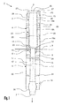
- FIG. 1 shows a device according to the invention in longitudinal section.
- the device 1 is used to cool or freeze elongated products, such as surimi, which is produced in an endless form and flash frozen in portions before being cut.
- the device 1 comprises an elongate, approximately tubular cooling tunnel 2 with a product inlet 3 and is functionally divided into a pre-cooling section 4 and an aftercooling section 6, between which an annular nozzle 5 is arranged.
- the cooled product exits the cooling tunnel 2 at a product outlet 7.
- the two-part annular nozzle 5 has an inner section 8 and an outer section 9 enclosing it radially on the outside.
- the inner portion 8 of the annular nozzle 5 is adapted at its narrowest point with its inner diameter to the outer diameter and optionally also the cross-sectional shape of a product to be cooled such that between the product surface and inner surface of the cooling channel 15 is only a small clear distance of a maximum of several millimeters to one centimeter , Towards the product outlet 7, the inner cross section of the inner section 8 widens slightly conically.
- the inner portion 8 has a refrigerant distributor 11 in the form of an all-round groove which is bounded radially on the outside by the outer portion 9 of the annular nozzle 5.
- the refrigerant distributor 11 is in fluid communication with an annular gap 12 which opens between the product-input-side end face of the inner section 8 and an inwardly projecting front section 14 of the outer section 9.
- a refrigerant which is supplied from a refrigerant supply line 13 to the refrigerant distributor 11, distributed in the refrigerant distributor 11 and flows uniformly over the entire circumference of the annular gap 12 in a predominantly central direction in the Interior of the cooling tunnel 2 a.
- the outer section 9 is arranged movably on the inner section 8 in the axial direction.
- the outer portion 9 is screwed onto the inner portion 8, and the width of the annular gap 12 can be adjusted by a corresponding rotation of the outer portion 9 relative to the inner portion 8 continuously in a wide range, for example 0 to 5 mm.
- the inner portion 8 of the annular nozzle 5 is connected on its side facing the product outlet 7 with a cooling channel 15, which also forms the part of the cooling tunnel 2 in the region of the aftercooling section 6.
- the cooling channel 15 can - as well as the Nachkühlabites 6 - have a length of about 50 cm up to a few meters and has an inner cross-section whose inside diameter is slightly larger than that of the inner cross section of the annular gap 5 at its narrowest point.
- the cooling channel 15 is provided with a widening 16; Furthermore, the cooling channel 15 has in its walls a number of openings 17 which are slot-shaped in the embodiment and arranged parallel to the longitudinal axis of the cooling tunnel 2, but also other geometries, such as circular or oval, have or extend at an angle to the longitudinal axis of the cooling tunnel 2 can. Conveniently, the cooling channel 15 is releasably connected to the other components of the device 1 and can be replaced if necessary, such as when changing the product to be cooled by another cooling channel.
- the pre-cooling section 4 composed in the exemplary embodiment of three fixed but detachably interconnected modular parts 19a, 19b, 19c comprises a cooling channel 20 which adjoins the outer section 9 of the annular nozzle 5 in the direction of the product inlet 2.
- the inner diameter of the cooling channel 20 is greater than the inner diameter of the cooling channel 15 and also greater than the minimum inner diameter of the annular nozzle 5, wherein a conical shaping of the front portion 14 of the annular nozzle 5 mediates the transition between the different inner diameters of the cooling channel 20 and annular nozzle 5.
- the annular nozzle 5 is a total of the type Venturi constructed whose narrowest point is in the region of the annular gap 12.
- the annular nozzle 5 nearest part 19c of the pre-cooling section 4 is fixed, but releasably connected to the outer portion 9 of the annular nozzle 5.
- the outer shell 22 is divided according to the modular structure of the device 1 into separable sections.
- the outer jacket 22 in each case has sections fixed radially on the outside to flanges 23 of the modular parts 19a, 19b, 19c.
- a tubular section of the outer jacket 22 is held with spacers 24 at a radial distance from the cooling channel 15. Holes are arranged as flow passages both in the spacers 24 and in the flanges 23, so that all cavities located between the outer jacket 22 and the cooling channels 15, 20 are fluidly connected to one another.
- a product inlet part 26 is mounted through which a plurality of equiangularly arranged and directed on the longitudinal axis 25 of the cooling tunnel 2 in the area in front of the product inlet 3 flow channels 27 are guided. Furthermore, the modular part 19a has towards the interior of the cooling channel 20 also a plurality of likewise arranged at equal angular intervals passages 28, which establish a flow connection between the interior of the cooling channel 20 and located between the outer shell 22 and the interior of the modular part 19a annulus 29.
- an elongated, for example rod, strand or tubular product is transported along the longitudinal axis 25 of the cooling tunnel 2 from the product inlet 3 to the product outlet 7.
- the product on bands not shown here to the device 1 out or away from the device 1.
- the product In the interior of the device 1 it is supported, as far as necessary, from the inner walls of the cooling channels 15, 20 from, or is passed over rails not shown here.
- the product requires no mechanical support inside the cooling tunnel. 2
- a refrigerant introduced via the refrigerant supply line 13 is applied to the product.
- the refrigerant heats up, in the case of a liquefied cryogenic refrigerant, like some liquid nitrogen, it evaporates.
- the carbon dioxide is preferably supplied under pressure in the liquefied state and relaxes upon exiting the annular nozzle 5 with strong cooling.
- the clearance of the annular space between outer shell 22 and cooling channel 15 mitigating expansion 16 additionally directs a portion of the refrigerant in the front, between outer shell 22 and cooling channel 20 located annular spaces.
- a portion of the refrigerant passes through the passages 28 in the modular part 19 a in the interior of the cooling channel 20, another part exits via the flow channels 27 and thus ensures a pre-cooling of the guided at the product inlet 3 in the cooling channel 2 product.
- the greater part of the inflowing into the annular space between the outer shell 22 and the cooling channel 15 refrigerant flows past the widening 16 through a rear opening 30 from.
- the cooling channel 15 of the aftercooling section 6 As the product passes through the cooling channel 15 of the aftercooling section 6, there is no direct charging of the product with supplied refrigerant. In the prevailing cool atmosphere there is a temperature balance inside the product, which leads to a more homogeneous temperature distribution over the entire product cross section. Across from Prior art cooling devices cool the surface of the product less and thus retain some of their resilience. This makes it possible to guide the product in subsequent processing steps on curved conveyor paths. If another product is to be cooled, parts of the device 1 can be easily exchanged, thus adapting the device 1 to the new product task.
- the cooling channel 15 can be replaced by a cooling channel of a different length or with a different inner profile in order to take into account the different geometry or the different thermal conductivity of another product. The same applies to the annular nozzle 5, which can also be replaced.
- the pre-cooling section 4 can be lengthened or shortened by adding or removing individual modular sections 19a, 19b, 19c.
- the device according to the invention is not limited to products of the food industry, but suitable for all elongated products in which a gentle cooling and uniform cooling of the product should take place, such as in the cooling of metal pipes after manufacture, or during extrusion for producing rods , Wires, tubes and irregularly shaped prismatic profiles.
Landscapes
- Engineering & Computer Science (AREA)
- Life Sciences & Earth Sciences (AREA)
- Chemical & Material Sciences (AREA)
- Wood Science & Technology (AREA)
- Zoology (AREA)
- Food Science & Technology (AREA)
- Polymers & Plastics (AREA)
- Combustion & Propulsion (AREA)
- Physics & Mathematics (AREA)
- Mechanical Engineering (AREA)
- Thermal Sciences (AREA)
- General Engineering & Computer Science (AREA)
Priority Applications (2)
| Application Number | Priority Date | Filing Date | Title |
|---|---|---|---|
| EP09100236A EP2241202B1 (fr) | 2009-04-15 | 2009-04-15 | Dispositif et procédé de refroidissement ou de gel de produits allongés |
| PL09100236T PL2241202T3 (pl) | 2009-04-15 | 2009-04-15 | Urządzenie i sposób chłodzenia lub zamrażania produktów wydłużonych |
Applications Claiming Priority (1)
| Application Number | Priority Date | Filing Date | Title |
|---|---|---|---|
| EP09100236A EP2241202B1 (fr) | 2009-04-15 | 2009-04-15 | Dispositif et procédé de refroidissement ou de gel de produits allongés |
Publications (2)
| Publication Number | Publication Date |
|---|---|
| EP2241202A1 true EP2241202A1 (fr) | 2010-10-20 |
| EP2241202B1 EP2241202B1 (fr) | 2013-02-27 |
Family
ID=41259422
Family Applications (1)
| Application Number | Title | Priority Date | Filing Date |
|---|---|---|---|
| EP09100236A Not-in-force EP2241202B1 (fr) | 2009-04-15 | 2009-04-15 | Dispositif et procédé de refroidissement ou de gel de produits allongés |
Country Status (2)
| Country | Link |
|---|---|
| EP (1) | EP2241202B1 (fr) |
| PL (1) | PL2241202T3 (fr) |
Cited By (1)
| Publication number | Priority date | Publication date | Assignee | Title |
|---|---|---|---|---|
| CN108277334A (zh) * | 2018-03-07 | 2018-07-13 | 中国科学院理化技术研究所 | 一种深冷处理设备及方法 |
Citations (10)
| Publication number | Priority date | Publication date | Assignee | Title |
|---|---|---|---|---|
| US3871190A (en) | 1965-12-27 | 1975-03-18 | Integral Process Syst Inc | Method and apparatus for flash freezing various products |
| US3898863A (en) * | 1972-06-19 | 1975-08-12 | Hollymatic Corp | Cryogenic refrigeration apparatus with automatic temperature control and automatic gas balance control |
| US4103507A (en) * | 1975-07-10 | 1978-08-01 | Airco, Inc. | High speed freezing system |
| US4757691A (en) * | 1986-06-18 | 1988-07-19 | Carboxyque Francaise | Cooling process and tunnel |
| US5478584A (en) * | 1995-02-15 | 1995-12-26 | Tyson Holding Company | Freezing system |
| JPH11164653A (ja) * | 1997-12-05 | 1999-06-22 | Takahashi Kogyo Kk | アイスクリーム等のソフト状軟質食品を対象とするハイブリッド急速凍結方法と装置 |
| US6167708B1 (en) | 1998-09-14 | 2001-01-02 | L'aire Liquide, Societe Anonyme Pour L'etude Et L'exploitation Des Procedes Georges Claude | Process and apparatus for the in-line freezing of products |
| US20010013227A1 (en) * | 1999-07-26 | 2001-08-16 | Praxair Technology Inc | Impingement cooler |
| US6622513B1 (en) * | 2000-12-21 | 2003-09-23 | David Howard | Freeze-crusting process and apparatus |
| EP1528340A1 (fr) | 2003-11-03 | 2005-05-04 | Linde Aktiengesellschaft | Appareil et procédé de refroidissement de produits |
-
2009
- 2009-04-15 EP EP09100236A patent/EP2241202B1/fr not_active Not-in-force
- 2009-04-15 PL PL09100236T patent/PL2241202T3/pl unknown
Patent Citations (10)
| Publication number | Priority date | Publication date | Assignee | Title |
|---|---|---|---|---|
| US3871190A (en) | 1965-12-27 | 1975-03-18 | Integral Process Syst Inc | Method and apparatus for flash freezing various products |
| US3898863A (en) * | 1972-06-19 | 1975-08-12 | Hollymatic Corp | Cryogenic refrigeration apparatus with automatic temperature control and automatic gas balance control |
| US4103507A (en) * | 1975-07-10 | 1978-08-01 | Airco, Inc. | High speed freezing system |
| US4757691A (en) * | 1986-06-18 | 1988-07-19 | Carboxyque Francaise | Cooling process and tunnel |
| US5478584A (en) * | 1995-02-15 | 1995-12-26 | Tyson Holding Company | Freezing system |
| JPH11164653A (ja) * | 1997-12-05 | 1999-06-22 | Takahashi Kogyo Kk | アイスクリーム等のソフト状軟質食品を対象とするハイブリッド急速凍結方法と装置 |
| US6167708B1 (en) | 1998-09-14 | 2001-01-02 | L'aire Liquide, Societe Anonyme Pour L'etude Et L'exploitation Des Procedes Georges Claude | Process and apparatus for the in-line freezing of products |
| US20010013227A1 (en) * | 1999-07-26 | 2001-08-16 | Praxair Technology Inc | Impingement cooler |
| US6622513B1 (en) * | 2000-12-21 | 2003-09-23 | David Howard | Freeze-crusting process and apparatus |
| EP1528340A1 (fr) | 2003-11-03 | 2005-05-04 | Linde Aktiengesellschaft | Appareil et procédé de refroidissement de produits |
Cited By (1)
| Publication number | Priority date | Publication date | Assignee | Title |
|---|---|---|---|---|
| CN108277334A (zh) * | 2018-03-07 | 2018-07-13 | 中国科学院理化技术研究所 | 一种深冷处理设备及方法 |
Also Published As
| Publication number | Publication date |
|---|---|
| PL2241202T3 (pl) | 2013-07-31 |
| EP2241202B1 (fr) | 2013-02-27 |
Similar Documents
| Publication | Publication Date | Title |
|---|---|---|
| DE1501212B1 (de) | Verfahren und Vorrichtung zum Tiefgefrieren von Nahrungsmitteln durch Kontakt mit Kuehlfluessigkeiten | |
| DE1451080A1 (de) | Einfrieranlage und Verfahren zum Einfrieren von Lebensmitteln | |
| DE2926628A1 (de) | Verfahren und anlage zum kontinuierlichen formen und bearbeiten von walzdraht aus stahl | |
| DE19708580A1 (de) | Behandlungsvorrichtung zum Behandeln von Erzeugnissen unter Einsatz eines gasförmigen Behandlungsmediums mit einem Förderer sowie Verfahren zum Betreiben derselben | |
| DE69824232T2 (de) | Gefriergerät | |
| DE2421667A1 (de) | Vorrichtung und verfahren zum gefrieren von material | |
| DE60004223T2 (de) | Integrierte anlage zur herstellung von walzgut | |
| DE69714642T2 (de) | Gerät und Verfahren zur oberflächlichen in-Line Abkühlung von Produkten | |
| EP3300486A1 (fr) | Procédé et dispositif pour le refroidissement de profilés extrudés | |
| EP1134522B1 (fr) | Refroidisseur de denrées alimentaires et procédé de refroidissement de denrées alimentaires | |
| EP2008040A1 (fr) | Procédé et dispositif pour dégivrer et nettoyer des ventilateurs | |
| EP2241202B1 (fr) | Dispositif et procédé de refroidissement ou de gel de produits allongés | |
| DE3241005C2 (fr) | ||
| DE2742320C3 (de) | Vorrichtung zum Kühlen von langgestreckten erwärmten Werkstücken | |
| EP1046436B1 (fr) | Procédé et lit de refroidissement pour produits laminés | |
| EP2657631B1 (fr) | Procédé et dispositif destinés au refroidissement de produits | |
| DE69401730T2 (de) | Verfahren zum Reinigen von Förderbändern für Lebensmittelgefrierung | |
| DE4320638A1 (de) | Verfahren und Anlage zum raschen Abkühlen eines in einem Warmwalzwerk verarbeitenden Walzgutes | |
| EP0976333B1 (fr) | Procédé et dispositif de fabrication de particules alimentaires | |
| CH656696A5 (de) | Verfahren und vorrichtung zum intensiven waerme- und/oder stoffaustausch, insbesondere in oefen. | |
| DE2608815A1 (de) | Verfahren und anlage zur kuehlung von zum verzehr bestimmten tierkoerpern | |
| AT508092B1 (de) | Vorrichtung zur reinigung und kühlung von werkstücken | |
| DE618160C (de) | Verfahren und Vorrichtung zum Eindampfen von Fluessigkeiten | |
| DE102023108620B4 (de) | Vorrichtung zum Kühlen bandförmiger Werkstücke | |
| DE19611047A1 (de) | Verfahren und Anlage zur Herstellung von neuem Längsholz-, insbesondere Leisten- und/oder Stabmaterial, das genannte neue Material und dessen Verwendung |
Legal Events
| Date | Code | Title | Description |
|---|---|---|---|
| PUAI | Public reference made under article 153(3) epc to a published international application that has entered the european phase |
Free format text: ORIGINAL CODE: 0009012 |
|
| AK | Designated contracting states |
Kind code of ref document: A1 Designated state(s): AT BE BG CH CY CZ DE DK EE ES FI FR GB GR HR HU IE IS IT LI LT LU LV MC MK MT NL NO PL PT RO SE SI SK TR |
|
| 17P | Request for examination filed |
Effective date: 20110420 |
|
| 17Q | First examination report despatched |
Effective date: 20110506 |
|
| RAP1 | Party data changed (applicant data changed or rights of an application transferred) |
Owner name: MESSER GROUP GMBH Owner name: MESSER FRANCE S.A.S. |
|
| GRAP | Despatch of communication of intention to grant a patent |
Free format text: ORIGINAL CODE: EPIDOSNIGR1 |
|
| GRAS | Grant fee paid |
Free format text: ORIGINAL CODE: EPIDOSNIGR3 |
|
| GRAA | (expected) grant |
Free format text: ORIGINAL CODE: 0009210 |
|
| AK | Designated contracting states |
Kind code of ref document: B1 Designated state(s): AT BE BG CH CY CZ DE DK EE ES FI FR GB GR HR HU IE IS IT LI LT LU LV MC MK MT NL NO PL PT RO SE SI SK TR |
|
| REG | Reference to a national code |
Ref country code: GB Ref legal event code: FG4D Free format text: NOT ENGLISH |
|
| REG | Reference to a national code |
Ref country code: CH Ref legal event code: EP |
|
| REG | Reference to a national code |
Ref country code: AT Ref legal event code: REF Ref document number: 598038 Country of ref document: AT Kind code of ref document: T Effective date: 20130315 |
|
| REG | Reference to a national code |
Ref country code: IE Ref legal event code: FG4D Free format text: LANGUAGE OF EP DOCUMENT: GERMAN |
|
| REG | Reference to a national code |
Ref country code: DE Ref legal event code: R096 Ref document number: 502009006347 Country of ref document: DE Effective date: 20130425 |
|
| REG | Reference to a national code |
Ref country code: NL Ref legal event code: T3 |
|
| REG | Reference to a national code |
Ref country code: LT Ref legal event code: MG4D |
|
| PG25 | Lapsed in a contracting state [announced via postgrant information from national office to epo] |
Ref country code: ES Free format text: LAPSE BECAUSE OF FAILURE TO SUBMIT A TRANSLATION OF THE DESCRIPTION OR TO PAY THE FEE WITHIN THE PRESCRIBED TIME-LIMIT Effective date: 20130607 Ref country code: NO Free format text: LAPSE BECAUSE OF FAILURE TO SUBMIT A TRANSLATION OF THE DESCRIPTION OR TO PAY THE FEE WITHIN THE PRESCRIBED TIME-LIMIT Effective date: 20130527 Ref country code: BG Free format text: LAPSE BECAUSE OF FAILURE TO SUBMIT A TRANSLATION OF THE DESCRIPTION OR TO PAY THE FEE WITHIN THE PRESCRIBED TIME-LIMIT Effective date: 20130527 Ref country code: LT Free format text: LAPSE BECAUSE OF FAILURE TO SUBMIT A TRANSLATION OF THE DESCRIPTION OR TO PAY THE FEE WITHIN THE PRESCRIBED TIME-LIMIT Effective date: 20130227 Ref country code: IS Free format text: LAPSE BECAUSE OF FAILURE TO SUBMIT A TRANSLATION OF THE DESCRIPTION OR TO PAY THE FEE WITHIN THE PRESCRIBED TIME-LIMIT Effective date: 20130627 Ref country code: SE Free format text: LAPSE BECAUSE OF FAILURE TO SUBMIT A TRANSLATION OF THE DESCRIPTION OR TO PAY THE FEE WITHIN THE PRESCRIBED TIME-LIMIT Effective date: 20130227 |
|
| REG | Reference to a national code |
Ref country code: PL Ref legal event code: T3 |
|
| PG25 | Lapsed in a contracting state [announced via postgrant information from national office to epo] |
Ref country code: FI Free format text: LAPSE BECAUSE OF FAILURE TO SUBMIT A TRANSLATION OF THE DESCRIPTION OR TO PAY THE FEE WITHIN THE PRESCRIBED TIME-LIMIT Effective date: 20130227 Ref country code: SI Free format text: LAPSE BECAUSE OF FAILURE TO SUBMIT A TRANSLATION OF THE DESCRIPTION OR TO PAY THE FEE WITHIN THE PRESCRIBED TIME-LIMIT Effective date: 20130227 Ref country code: PT Free format text: LAPSE BECAUSE OF FAILURE TO SUBMIT A TRANSLATION OF THE DESCRIPTION OR TO PAY THE FEE WITHIN THE PRESCRIBED TIME-LIMIT Effective date: 20130627 Ref country code: LV Free format text: LAPSE BECAUSE OF FAILURE TO SUBMIT A TRANSLATION OF THE DESCRIPTION OR TO PAY THE FEE WITHIN THE PRESCRIBED TIME-LIMIT Effective date: 20130227 Ref country code: GR Free format text: LAPSE BECAUSE OF FAILURE TO SUBMIT A TRANSLATION OF THE DESCRIPTION OR TO PAY THE FEE WITHIN THE PRESCRIBED TIME-LIMIT Effective date: 20130528 |
|
| PG25 | Lapsed in a contracting state [announced via postgrant information from national office to epo] |
Ref country code: HR Free format text: LAPSE BECAUSE OF FAILURE TO SUBMIT A TRANSLATION OF THE DESCRIPTION OR TO PAY THE FEE WITHIN THE PRESCRIBED TIME-LIMIT Effective date: 20130227 |
|
| PG25 | Lapsed in a contracting state [announced via postgrant information from national office to epo] |
Ref country code: DK Free format text: LAPSE BECAUSE OF FAILURE TO SUBMIT A TRANSLATION OF THE DESCRIPTION OR TO PAY THE FEE WITHIN THE PRESCRIBED TIME-LIMIT Effective date: 20130227 Ref country code: EE Free format text: LAPSE BECAUSE OF FAILURE TO SUBMIT A TRANSLATION OF THE DESCRIPTION OR TO PAY THE FEE WITHIN THE PRESCRIBED TIME-LIMIT Effective date: 20130227 Ref country code: RO Free format text: LAPSE BECAUSE OF FAILURE TO SUBMIT A TRANSLATION OF THE DESCRIPTION OR TO PAY THE FEE WITHIN THE PRESCRIBED TIME-LIMIT Effective date: 20130227 Ref country code: CZ Free format text: LAPSE BECAUSE OF FAILURE TO SUBMIT A TRANSLATION OF THE DESCRIPTION OR TO PAY THE FEE WITHIN THE PRESCRIBED TIME-LIMIT Effective date: 20130227 Ref country code: SK Free format text: LAPSE BECAUSE OF FAILURE TO SUBMIT A TRANSLATION OF THE DESCRIPTION OR TO PAY THE FEE WITHIN THE PRESCRIBED TIME-LIMIT Effective date: 20130227 |
|
| PG25 | Lapsed in a contracting state [announced via postgrant information from national office to epo] |
Ref country code: CY Free format text: LAPSE BECAUSE OF FAILURE TO SUBMIT A TRANSLATION OF THE DESCRIPTION OR TO PAY THE FEE WITHIN THE PRESCRIBED TIME-LIMIT Effective date: 20130227 Ref country code: MC Free format text: LAPSE BECAUSE OF FAILURE TO SUBMIT A TRANSLATION OF THE DESCRIPTION OR TO PAY THE FEE WITHIN THE PRESCRIBED TIME-LIMIT Effective date: 20130227 |
|
| REG | Reference to a national code |
Ref country code: CH Ref legal event code: PL |
|
| PLBE | No opposition filed within time limit |
Free format text: ORIGINAL CODE: 0009261 |
|
| STAA | Information on the status of an ep patent application or granted ep patent |
Free format text: STATUS: NO OPPOSITION FILED WITHIN TIME LIMIT |
|
| GBPC | Gb: european patent ceased through non-payment of renewal fee |
Effective date: 20130527 |
|
| REG | Reference to a national code |
Ref country code: IE Ref legal event code: MM4A |
|
| PG25 | Lapsed in a contracting state [announced via postgrant information from national office to epo] |
Ref country code: LI Free format text: LAPSE BECAUSE OF NON-PAYMENT OF DUE FEES Effective date: 20130430 Ref country code: CH Free format text: LAPSE BECAUSE OF NON-PAYMENT OF DUE FEES Effective date: 20130430 |
|
| 26N | No opposition filed |
Effective date: 20131128 |
|
| REG | Reference to a national code |
Ref country code: DE Ref legal event code: R097 Ref document number: 502009006347 Country of ref document: DE Effective date: 20131128 |
|
| PG25 | Lapsed in a contracting state [announced via postgrant information from national office to epo] |
Ref country code: GB Free format text: LAPSE BECAUSE OF NON-PAYMENT OF DUE FEES Effective date: 20130527 Ref country code: IE Free format text: LAPSE BECAUSE OF NON-PAYMENT OF DUE FEES Effective date: 20130415 |
|
| PG25 | Lapsed in a contracting state [announced via postgrant information from national office to epo] |
Ref country code: MT Free format text: LAPSE BECAUSE OF FAILURE TO SUBMIT A TRANSLATION OF THE DESCRIPTION OR TO PAY THE FEE WITHIN THE PRESCRIBED TIME-LIMIT Effective date: 20130227 |
|
| REG | Reference to a national code |
Ref country code: AT Ref legal event code: MM01 Ref document number: 598038 Country of ref document: AT Kind code of ref document: T Effective date: 20140415 |
|
| PG25 | Lapsed in a contracting state [announced via postgrant information from national office to epo] |
Ref country code: TR Free format text: LAPSE BECAUSE OF FAILURE TO SUBMIT A TRANSLATION OF THE DESCRIPTION OR TO PAY THE FEE WITHIN THE PRESCRIBED TIME-LIMIT Effective date: 20130227 |
|
| PG25 | Lapsed in a contracting state [announced via postgrant information from national office to epo] |
Ref country code: MK Free format text: LAPSE BECAUSE OF FAILURE TO SUBMIT A TRANSLATION OF THE DESCRIPTION OR TO PAY THE FEE WITHIN THE PRESCRIBED TIME-LIMIT Effective date: 20130227 Ref country code: HU Free format text: LAPSE BECAUSE OF FAILURE TO SUBMIT A TRANSLATION OF THE DESCRIPTION OR TO PAY THE FEE WITHIN THE PRESCRIBED TIME-LIMIT; INVALID AB INITIO Effective date: 20090415 Ref country code: LU Free format text: LAPSE BECAUSE OF NON-PAYMENT OF DUE FEES Effective date: 20130415 |
|
| PG25 | Lapsed in a contracting state [announced via postgrant information from national office to epo] |
Ref country code: AT Free format text: LAPSE BECAUSE OF NON-PAYMENT OF DUE FEES Effective date: 20140415 |
|
| REG | Reference to a national code |
Ref country code: FR Ref legal event code: PLFP Year of fee payment: 8 |
|
| PGFP | Annual fee paid to national office [announced via postgrant information from national office to epo] |
Ref country code: IT Payment date: 20160418 Year of fee payment: 8 |
|
| REG | Reference to a national code |
Ref country code: FR Ref legal event code: PLFP Year of fee payment: 9 |
|
| REG | Reference to a national code |
Ref country code: FR Ref legal event code: PLFP Year of fee payment: 10 |
|
| PG25 | Lapsed in a contracting state [announced via postgrant information from national office to epo] |
Ref country code: IT Free format text: LAPSE BECAUSE OF NON-PAYMENT OF DUE FEES Effective date: 20170415 |
|
| PGFP | Annual fee paid to national office [announced via postgrant information from national office to epo] |
Ref country code: BE Payment date: 20180314 Year of fee payment: 10 Ref country code: PL Payment date: 20180316 Year of fee payment: 10 Ref country code: FR Payment date: 20180315 Year of fee payment: 10 |
|
| PGFP | Annual fee paid to national office [announced via postgrant information from national office to epo] |
Ref country code: NL Payment date: 20180412 Year of fee payment: 10 |
|
| PGFP | Annual fee paid to national office [announced via postgrant information from national office to epo] |
Ref country code: DE Payment date: 20190430 Year of fee payment: 11 |
|
| REG | Reference to a national code |
Ref country code: NL Ref legal event code: MM Effective date: 20190501 |
|
| REG | Reference to a national code |
Ref country code: BE Ref legal event code: MM Effective date: 20190430 |
|
| PG25 | Lapsed in a contracting state [announced via postgrant information from national office to epo] |
Ref country code: NL Free format text: LAPSE BECAUSE OF NON-PAYMENT OF DUE FEES Effective date: 20190501 |
|
| PG25 | Lapsed in a contracting state [announced via postgrant information from national office to epo] |
Ref country code: BE Free format text: LAPSE BECAUSE OF NON-PAYMENT OF DUE FEES Effective date: 20190430 Ref country code: FR Free format text: LAPSE BECAUSE OF NON-PAYMENT OF DUE FEES Effective date: 20190430 |
|
| REG | Reference to a national code |
Ref country code: DE Ref legal event code: R119 Ref document number: 502009006347 Country of ref document: DE |
|
| PG25 | Lapsed in a contracting state [announced via postgrant information from national office to epo] |
Ref country code: DE Free format text: LAPSE BECAUSE OF NON-PAYMENT OF DUE FEES Effective date: 20201103 |
|
| PG25 | Lapsed in a contracting state [announced via postgrant information from national office to epo] |
Ref country code: PL Free format text: LAPSE BECAUSE OF NON-PAYMENT OF DUE FEES Effective date: 20190415 |