EP2240908B1 - Génération d'un produit à image améliorée - Google Patents
Génération d'un produit à image améliorée Download PDFInfo
- Publication number
- EP2240908B1 EP2240908B1 EP09707855.4A EP09707855A EP2240908B1 EP 2240908 B1 EP2240908 B1 EP 2240908B1 EP 09707855 A EP09707855 A EP 09707855A EP 2240908 B1 EP2240908 B1 EP 2240908B1
- Authority
- EP
- European Patent Office
- Prior art keywords
- image
- images
- printing
- tangible surface
- window
- Prior art date
- Legal status (The legal status is an assumption and is not a legal conclusion. Google has not performed a legal analysis and makes no representation as to the accuracy of the status listed.)
- Active
Links
- 238000007639 printing Methods 0.000 claims description 80
- 230000000007 visual effect Effects 0.000 claims description 55
- 238000004458 analytical method Methods 0.000 claims description 33
- 238000012545 processing Methods 0.000 claims description 28
- 238000000034 method Methods 0.000 claims description 27
- 238000009432 framing Methods 0.000 claims description 19
- 238000003672 processing method Methods 0.000 claims description 16
- 230000002996 emotional effect Effects 0.000 claims description 8
- 239000003086 colorant Substances 0.000 claims description 4
- 230000009471 action Effects 0.000 claims description 3
- 238000009877 rendering Methods 0.000 claims description 3
- 239000000047 product Substances 0.000 description 73
- 238000004891 communication Methods 0.000 description 14
- 238000004422 calculation algorithm Methods 0.000 description 7
- 238000005516 engineering process Methods 0.000 description 6
- 230000003287 optical effect Effects 0.000 description 4
- 230000008569 process Effects 0.000 description 4
- 238000013461 design Methods 0.000 description 3
- 238000004141 dimensional analysis Methods 0.000 description 3
- 238000001914 filtration Methods 0.000 description 3
- 230000033001 locomotion Effects 0.000 description 3
- 239000000463 material Substances 0.000 description 3
- 241001465754 Metazoa Species 0.000 description 2
- 241000238370 Sepia Species 0.000 description 2
- 230000000386 athletic effect Effects 0.000 description 2
- 230000005540 biological transmission Effects 0.000 description 2
- 238000009826 distribution Methods 0.000 description 2
- 230000000694 effects Effects 0.000 description 2
- 210000000887 face Anatomy 0.000 description 2
- 238000003707 image sharpening Methods 0.000 description 2
- 230000003993 interaction Effects 0.000 description 2
- 238000004519 manufacturing process Methods 0.000 description 2
- 238000012546 transfer Methods 0.000 description 2
- 241000533950 Leucojum Species 0.000 description 1
- 244000027321 Lychnis chalcedonica Species 0.000 description 1
- 238000013459 approach Methods 0.000 description 1
- 238000013528 artificial neural network Methods 0.000 description 1
- 230000000903 blocking effect Effects 0.000 description 1
- 230000036760 body temperature Effects 0.000 description 1
- 230000001413 cellular effect Effects 0.000 description 1
- 238000006243 chemical reaction Methods 0.000 description 1
- 238000007635 classification algorithm Methods 0.000 description 1
- 238000004040 coloring Methods 0.000 description 1
- 238000002508 contact lithography Methods 0.000 description 1
- 238000013500 data storage Methods 0.000 description 1
- 230000001419 dependent effect Effects 0.000 description 1
- 238000001514 detection method Methods 0.000 description 1
- 238000009792 diffusion process Methods 0.000 description 1
- 230000003292 diminished effect Effects 0.000 description 1
- 230000004424 eye movement Effects 0.000 description 1
- 239000004744 fabric Substances 0.000 description 1
- 230000006870 function Effects 0.000 description 1
- 230000002068 genetic effect Effects 0.000 description 1
- 239000011521 glass Substances 0.000 description 1
- 239000010410 layer Substances 0.000 description 1
- 239000004973 liquid crystal related substance Substances 0.000 description 1
- 230000007246 mechanism Effects 0.000 description 1
- 230000003340 mental effect Effects 0.000 description 1
- 238000012986 modification Methods 0.000 description 1
- 230000004048 modification Effects 0.000 description 1
- 230000007935 neutral effect Effects 0.000 description 1
- 238000004806 packaging method and process Methods 0.000 description 1
- 229910000498 pewter Inorganic materials 0.000 description 1
- 239000010957 pewter Substances 0.000 description 1
- 230000001681 protective effect Effects 0.000 description 1
- 239000011241 protective layer Substances 0.000 description 1
- 230000010344 pupil dilation Effects 0.000 description 1
- 238000002310 reflectometry Methods 0.000 description 1
- 238000012216 screening Methods 0.000 description 1
- 238000000926 separation method Methods 0.000 description 1
- 239000007787 solid Substances 0.000 description 1
- 239000013589 supplement Substances 0.000 description 1
- 238000007651 thermal printing Methods 0.000 description 1
- 239000012780 transparent material Substances 0.000 description 1
Images


Classifications
-
- G—PHYSICS
- G06—COMPUTING; CALCULATING OR COUNTING
- G06T—IMAGE DATA PROCESSING OR GENERATION, IN GENERAL
- G06T11/00—2D [Two Dimensional] image generation
- G06T11/60—Editing figures and text; Combining figures or text
Definitions
- the present invention relates to the field of using works of communication, and in particular the creation, sharing and production of works of communication.
- Personalized image collages, clothing, albums and other image enhanced items are becoming increasingly more accessible at the retail level as printing and digital technologies improve and drop in cost.
- the ability to deliver a personalized image bearing product has become more accessible, the novelty and perceived value of such gifts has diminished and consumers have become more discriminating.
- consumers now seek items that bear customized images in a more seamless and integrated manner.
- few consumers are equipped with the combination of artistic, aesthetic and technical gifts necessary to successfully master such items. Further, those who are so equipped often lack the time necessary to do this task effectively.
- Document WO 01/82231A2 discloses a system and method for organizing images in a predetermined page format. Digital images are grouped in different page layouts and a page layout is selected based on predetermined criteria.
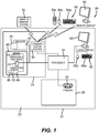
- FIGS. 1 illustrates a first embodiment of an electronic system 20 that can be used in generating an image enhanced product.
- electronic system 20 comprises a housing 22 and a source of content data files 24, a user input system 26 and an output system 28 connected to a processor 34.
- the source of content data files 24, user input system 26 or output system 28 and processor 34 can be located within housing 22 as illustrated.
- circuits and systems of the source of content data files 24, user input system 26 or output system 28 can be located in whole or in part outside of housing 22.
- the source of content data files 24 can include any form of electronic or other circuit or system that can supply digital data to processor 34 from which processor 34 can derive images for use in forming an image enhanced item.
- the content data files can comprise, for example and without limitation, still images, image sequences, video graphics, and computer generated images.
- Source of content data files 24 can optionally capture images to create content data for use in content data files by use of capture devices located at electronic system 20 and/or can obtain content data files that have been prepared by or using other devices.
- source of content data files 24 includes sensors 38, a memory 40 and a communication system 54.
- Sensors 38 are optional and can include light sensors, biometric sensors and other sensors known in the art that can be used to detect conditions in the environment of system 20 and to convert this information into a form that can be used by processor 34 of system 20. Sensors 38 can also include one or more video sensors 39 that are adapted to capture images. Sensors 38 can also include biometric or other sensors for measuring involuntary physical and mental reactions such sensors including, but not limited to, voice inflection, body movement, eye movement, pupil dilation, body temperature, and p4000 wave sensors.
- Memory 40 can include conventional memory devices including solid state, magnetic, optical or other data storage devices. Memory 40 can be fixed within system 20 or it can be removable. In the embodiment of FIG. 1 , system 20 is shown having a hard drive 42, a disk drive 44 for a removable disk such as an optical, magnetic or other disk memory (not shown) and a memory card slot 46 that holds a removable memory 48 such as a removable memory card and has a removable memory interface 50 for communicating with removable memory 48. Data including, but not limited to, control programs, digital images and metadata can also be stored in a remote memory system 52 such as a personal computer, computer network or other digital system.
- a remote memory system 52 such as a personal computer, computer network or other digital system.
- system 20 has a communication system 54 that in this embodiment can be used to communicate with an optional remote memory system 52, an optional a remote display 56, and/or optional remote input 58.
- a remote input station including a remote display 56 and/or remote input controls 58 can communicate with communication system 54 wirelessly as illustrated or can communicate in a wired fashion.
- a local input station including either or both of a local display 66 and local input controls 68 can be connected to communication system 54 using a wired or wireless connection.
- Communication system 54 can comprise for example, one or more optical, radio frequency or other transducer circuits or other systems that convert image and other data into a form that can be conveyed to a remote device such as remote memory system 52 or remote display 56 using an optical signal, radio frequency signal or other form of signal.
- Communication system 54 can also be used to receive a digital image and other data from a host or server computer or network (not shown), a remote memory system 52 or a remote input 58.
- Communication system 54 provides processor 34 with information and instructions from signals received thereby.
- communication system 54 will be adapted to communicate with the remote memory system 52 by way of a communication network such as a conventional telecommunication or data transfer network such as the internet, a cellular, peer-to-peer or other form of mobile telecommunication network, a local communication network such as wired or wireless local area network or any other conventional wired or wireless data transfer system.
- a communication network such as a conventional telecommunication or data transfer network such as the internet, a cellular, peer-to-peer or other form of mobile telecommunication network, a local communication network such as wired or wireless local area network or any other conventional wired or wireless data transfer system.
- User input system 26 provides a way for a user of system 20 to provide instructions to processor 34. This allows such a user to make a designation of content data files to be used in generating an image enhanced output product and to select an output form for the output product.
- User input system 26 can also be used for a variety of other purposes including, but not limited to, allowing a user to arrange, organize and edit content data files to be incorporated into the image enhanced output product, to provide information about the user or audience, to provide annotation data such as voice and text data, to identify characters in the content data files, and to perform such other interactions with system 20 as will be described later.
- user input system 26 can comprise any form of transducer or other device capable of receiving an input from a user and converting this input into a form that can be used by processor 34.
- user input system 26 can comprise a touch screen input, a touch pad input, a 4-way switch, a 6-way switch, an 8-way switch, a stylus system, a trackball system, a joystick system, a voice recognition system, a gesture recognition system a keyboard, a remote control or other such systems.
- user input system 26 includes an optional remote input 58 including a remote keyboard 58a, a remote mouse 58b, and a remote control 58c and a local input 68 including a local keyboard 68a and a local mouse 68b.
- Remote input 58 can take a variety of forms, including, but not limited to, the remote keyboard 58a, remote mouse 58b or remote control handheld device 58c illustrated in FIG. 1 .
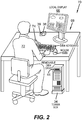
- local input 68 can take a variety of forms. In the embodiment of FIG. 1 , local display 66 and local user input 68 are shown directly connected to processor 34.
- local user input 68 can take the form of an editing studio or kiosk 70 (hereafter also referred to as an "editing area 70").
- an editing area 70 can also have sensors 38 including, but not limited to, video sensors 39, audio sensors 74 and other sensors such as multispectral sensors that can monitor user 72 during a usering or production session.
- Output system 28 is used for rendering images, text or other graphical representations in a manner that allows image enhanceable item to be converted into an image enhanced product.
- output system 28 can comprise any conventional structure or system that is known for printing or recording images, including, but not limited to, printer 29.
- Printer 29 can record images on a tangible surface 30 using a variety of known technologies including, but not limited to, conventional four color offset separation printing or other contact printing, silk screening, dry electrophotography such as is used in the NexPress 2100 printer sold by Eastman Kodak Company, Rochester, New York, USA, thermal printing technology, drop on demand ink jet technology and continuous inkjet technology.
- printer 29 will be described as being of a type that generates color images. However, it will be appreciated that this is not necessary and that the claimed methods and apparatuses herein can be practiced with a printer 29 that prints monotone images such as black and white, grayscale or sepia toned images.
- the source of content data files 24, user input system 26 and output system 28 can share components.
- Processor 34 operates system 20 based upon signals from user input system 26, sensors 38, memory 40 and communication system 54.
- Processor 34 can include, but is not limited to, a programmable digital computer, a programmable microprocessor, a programmable logic processor, a series of electronic circuits, a series of electronic circuits reduced to the form of an integrated circuit, or a series of discrete components.
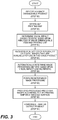
- FIG. 3 what is illustrated is a first embodiment of a method for using an image enhanceable item to generate an image enhanced output product that can be executed, for example, by the system 20 of FIGS. 1 and 2 .
- an image enhanceable product is identified (step 80). Typically, this is done when a user input system 26 detects that user 72 has made a user input action that can be interpreted by processor 34 as a selection of one of a plurality of possible image enhanceable items.
- the type of image enhanceable item can be identified based upon stored information regarding user 72 or some other person including, but not limited to, user preferences, past user interactions and other factors. It will be appreciated that such an identification can be made automatically when, for example, it is determined that system 20 is optimized or otherwise configured to generate only one type of image enhanced output product.
- an image enhanceable item 100 includes anything that has a tangible surface 30 on which a plurality of images can be formed, located, placed or otherwise provided.
- an image enhanceable item 100 can take the form of a collage, photo book, scrap book, photo calendar, mug, stein, cup, stemware, jewelry, tile, mosaic, home decor, mousepads, pillowcases, pen & pencil holders, a simulated or actual bushstroke image on canvas, a photo-realistic image on a canvas, a keepsake box, a fleece blanket, coasters, frames, ornaments, round ornament, snowflake ornament, filigree ornament, pewter ornament, holiday ornament set, annual ornament set, playing cards, puzzle, teddy bear or other stuffed animal, wall paper, packaging, apparel & accessories, including, but not limited to, a T-shirt, a tie, a tote bag, apron, baby onesie, performance shirt, and/or frame, matte and image combinations and collages, mailing labels, gift tags stamp
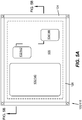
- FIG. 4 shows one, non-limiting, example of an image enhanceable item 100.
- this image enhanceable item 100 comprises a tangible surface 30 that is provided in the form of a sheet.
- image enhanceable item 100 is shown having an image receiving area 102 that comprises less than all of a first side 104 of tangible surface 30.
- image receiving area 102 can comprise the entire width and/or length and/or depth of tangible surface 30.
- the image receiving area 102 can comprise substantially less than all of an available tangible surface 30 of an image enhanceable item 100.
- image receiving area 102 can include a plurality of window areas 106, 108 and 110 in which images are preferably recorded.
- Inter-window area 112 is illustrated as having a stipple pattern recorded thereon so as to better illustrate the boundaries of window areas 106, 108 and 110.
- inter-window area 112 can be blank, colored, textured, and/or can support images, text or other forms of graphic information, and/or can support, or can bear or can be left to bear other articles such as artifacts, separate labels or other items that can be joined to tangible surface 30.
- Inter-window area 112 can be reflective or translucent as desired, inter-window area 112 can also have a matte finish, glossy finish or semi-gloss finish as desired.
- FIGS. 5A and 5B show, respectively, a top view and a section elevation view of another, non-limiting example of an image enhanceable product 100.
- image enhanceable product 100 comprises a conventional matte and frame combination 118 having an external structural frame 124, with a light transmissive area 126 and an internal area 128 that is adapted to hold a framing matte 120 and a tangible surface 30.
- framing matte 120 defines a plurality of windows 130, 132 and 134 that allow light to pass through an inter-window area 136 of framing matte 120 so that portions 140, 142 and 144 of tangible surface 30 that are registered with windows 130, 132 and 134 can be seen outside of framing system 120 while other portions of tangible surface 30 are blocked from view.
- windows 130, 132 and 134 are essentially transparent and can optionally comprise openings through framing matte 120.
- windows 130, 132, and 134 can comprise transparent or semi-transparent materials that allow light to pass therethrough in a modified form.
- windows 130, 132, and 134 can filter, soften, or even selectively block portions of light passing therethrough as may be desired.
- liquid crystal display or other active or semi-active light blocking materials can be used.
- filtering can be performed for artistic or aesthetic purposes, while in the same or other embodiments, filtering can be protective such as where the filtering blocks forms of light that can damage framing matte 120 or tangible surface 30 or damage images that are recorded thereon.
- Light transmissive area 126 can similarly include such a light transmissive material as desired .
- ambient or other light passes through light transmissive area 126 travels to framing matte 120 or onto tangible surface 30.
- This light is reflectively modulated by images 140, 142 and 144 and/or inter-window areas 136 of framing matte 120 and returns through light transmissive area 126 so that the modulated light is viewable outside of framing system 118.
- light transmissive area 126 can comprise for example, and without limitation an opening between an observer and framing matte 120 and tangible surface 30.
- internal area 128 is also sized and shaped to hold an optional backing support 129, which can have, for example, mounting structures (not shown) such as hook mountings and the like defined therein.
- internal area 128 can optionally be sized to hold a protection layer such as a glass or other transparent or semitransparent sheet (not shown) of conventional design to protect and/or hold framing matte 120 and tangible surface 30.
- FIG. 6 illustrates yet another example of an image enhanceable output product 100 comprising a conventional tote bag 150 having tangible surface 30 in the form of image bearing surface 152 with window areas 154, 156, and 158 in which images can be provided.
- tote bag 150 has straps 160, pocket area 162 and seams 164 and 166 that are visible image bearing surface 152.
- the image enhanceable output product 100 can take any variety of forms.
- a printing map is then determined (step 82) that defines a plurality of window areas in which images are to be printed on tangible surface 30.
- Each window is defined at least by a window shape, optionally, an available image resolution, and location information defining a location of the image window relative to tangible surface 30.
- the window shape can be defined using any known logical system for defining shapes.
- the window shapes can be defined by reference to well known geometric constructs, mathematical algorithms or in any other form or manner of defining a shape known in the art of image processing, geometry, computer science or other relevant arts.
- the optional available image resolution for a particular window characterizes or identifies the extent to which image picture elements can be recorded within the window shape by output system 28.
- this available image resolution will be determined based upon a size and shape of a window and the density of picture elements that output system 28 can record on tangible surface 30.
- the location information defines, in some manner, a location or position on tangible surface 30 in which the window shapes are to be defined.
- the location information can be located in any known fashion.
- the location information can define a location of the window shape relative to the tangible surface based upon predetermined characteristics of the tangible surface 30, such as perforations, edge locations or margins of the tangible surface 30, or it can define the location of the window shape based upon markers, watermarks, printed text, printed images, seam locations, fabric patterns or other visible features on tangible surface 30.
- the location information can define a location for the window based upon the location of other surfaces that are joined to tangible surface 30 such as for example, and without limitation, straps 160.
- the printing map can be determined at least in part by obtaining an image enhanceable product identification and determining the printing map by using the product identification to obtain a stored printing map or to obtain previously stored information that can be used to create a printing map, including, but not limited to, pre-stored image shape information, image location information, pattern information and/or algorithms that can be used to determine such information.
- image shape information e.g., image shape information
- image location information e.g., text, codes and/or radio frequency identifiers that uniquely identify the good being sold.
- a user input system 26 or sensor 38 can include an appropriate reader of conventional design to read the identification.
- a user can enter an identification into user input 26 manually.
- system 20 can have a user input system 26 or sensors 38 that incorporate an image input source such as a scanner or image capture device of conventional design that can be arranged to capture an image of image enhanced product 100 including tangible surface 30 or a framing or matting system 110 into which tangible surface 30 is to be placed. This image can be examined to determine a product identification for the image enhanced product 100 that can then be used as noted above to identify the image enhanced product.
- system 20 can execute algorithms to identify portions of tangible surface 30 that are available window areas on tangible surface 30. This analysis can be done automatically based upon rules for identifying image bearing areas of the article. For example, areas of continuous background color in the captured image can be identified as one or more potential window areas and used to form one or more printing maps. Similarly, areas of continuous areas on tangible surface 30 can be identified as window areas and used to form a printing map. Any known algorithm that is suitable for identifying printable areas on a tangible surface 30 can be used for the purpose of generating a printing map.
- system 20 can request that a user make an input using user input system 26 to select from among the plurality of available printing maps.
- system 20 shows a screen shot on local display 66 of a user a plurality of available printing maps 170, 172 and 174, that can be used to print on tangible surface 30 as well as the option 176 to seek additional printing map options.
- printing map one 170 includes one large vertically oriented image 180 and two small images 182
- printing map two 172 includes one large vertically oriented image 180 and four small images 182
- printing map three 174 incorporates four small images 182 and one landscape or wide aspect ratio image 184.
- a user who is not satisfied with the selection of options can make a more options selection using, for example, button 176 which can obtain additional printing maps from those that may be associated with the image enhanced item. Where more than three printing maps are available, the additional options button 176 can be omitted from presentation by system 20.
- a user 72 can then use user input 26 to drag and/or drop a selected template on to a drawing, map, picture or other representation 188 of tangible surface 30 or take such other user input actions as are necessary to indicate that user 72 wished to select one of the templates.
- the user has selected template 174 and has used a drag and drop technique to indicate that this template is to be generally center mounted with in a representation of the sheet type image enhanceable product 100 of FIG. 4 .
- At least one visual impact characteristic for the image enhanced output Product is then determined based upon the appearance of image enhanceable item 100 and the printing map (step 84).
- the visual impact characteristic for image enhanceable item 100 will be defined based upon an overall combination of visual features of the image enhanceable item 100 that can be observed by a viewer who is positioned to view at least one of the windows identified by the printing map.
- FIG. 9 illustrates one example of an image enhanced output product 116 that is formed based upon the image enhanceable product 100 that is illustrated in the embodiment of FIG. 4 . As is shown in FIG. 9 , the overall appearance is dictated by the appearance of the inter-window area 112 as well as images that are recorded in window areas 106, 108 and 110.
- FIG. 10 illustrates one example of an image enhanced output product 148 that is formed based upon the frame and matting combination 118 that is illustrated in the embodiment of FIGS. 5A and 5B .
- the visual impact of the image enhanced object includes the appearance of images 140, 142 and 144, the appearance of framing matte 120 and the appearance of structural frame 124.
- the visual components of the embodiment of FIGS. 5A and 5B can include the visual appearance of any material in light transmissive area 126 or in windows 130, 132, or 134.
- FIG. 11 illustrates an example of an image enhanced output product 177 formed comprising a conventional tote bag 150 having tangible surface 30 in the form of image bearing surface 152 with window areas 154, 156, and 158 in which images 155, 157 and 159 have been provided.
- tote bag 150 has straps 160, pocket area 162 and seams 164 and 166 that are visible image bearing surface 152, the appearance of which should be considered when determining the visual impact of an image enhanced output product that will be formed therefrom.
- FIGS. 9 , 10 and 11 make it clear that the visual impact of an image enhanced output product will be influenced at least by the appearance of tangible surface 30 as well as any other portions of image enhanceable item 100 that are visible when viewed from a perspective that also allows a viewer to observe images that are recorded in the pattern of windows called for by the printing map. All of these factors deserve consideration in determining how to process images for use on the image enhanced item.
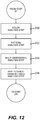
- FIG. 12 shows one embodiment of a method for analyzing the image enhanceable product 100 to determine information that can be used during the process of determining the visual impact characteristic.
- a color analysis is performed on the image enhanceable product.
- This color analysis (step 200) identifies one or more dominant colors that are present at least in the portions of image enhanceable item 100 that will be visible when images are recorded on the image enhanceable item 100 in accordance with the printing map.
- the color analysis step can also identify gamma and chrominance and other color characteristics of the image enhanceable item 100.
- the color analysis step can be used to provide color statistics, color histograms and other information relative to the color of the image enhanceable object or other forms of color information that can be used to determine a visual impact characteristic.
- a pattern analysis (step 202) is then performed.
- the pattern analysis evaluates shapes, patterns and forms on at least those portions of the image enhanceable item 100 that will be visible when images are recorded on the image enhanceable item 100 in accordance with the selected printing map. Pattern information can then be provided that characterizes the nature of the pattern, the frequency of the patterns, the shapes, sizes and locations of existing patterns on the image enhanceable product.
- the step of performing pattern analysis comprises executing an automated pattern classification algorithm.
- the pattern analysis step 202 can be performed before the step of color analysis so that the color analysis is performed according to the patterns so that for example, the colors of particularly important patterns and shapes are tracked with precision and so that color analysis can be made in a more accurate fashion by allowing color analysis to be organized in accordance with the tracked patterns so as to prevent misinterpretation of color data.
- color analysis of straps 160 can be performed separately from color analysis of tangible surface 30. This can result in better color analysis of both portions of the tote bag 150.
- a multi-dimensional analysis (step 204) can also be performed that looks for variations in depth on at least those portions of the image enhanceable product 100 that will be visible when images are recorded on the image enhanceable product 100 in accordance with the printing map. It will be appreciated that such contours can also exert a significant influence on the overall appearance of the image enhanceable product. In one embodiment, such multi-dimensional analysis considers the extent to which contours influence the apparent colors and/or distribution of images that will be provided according to the printing map.
- a transmissivity/reflectance analysis can also be performed that indicates the refection and transmission characteristics of image enhanceable item 100 so the reflectivity or transmissivity of a protective layer or matte system or a framing system can be characterized automatically to identify whether an image enhanceable item 100 is adapted to present images in a form that will be modified, or that will have certain characteristics such as diffused imagery, or highly transmissive or reflective imagery.
- a particular framing system such as the framing system 118 of FIGS. 5A and 5B , has a plurality of components such as structural frame 124, light transmissive area 126 or other regions that can vary in reflectance and/or in light diffusion characteristics.
- a light reflectance analysis can determine different information when these components are defined in a manner that softens the light or conversely when such components are defined in a manner that provides for high transmission or reflectance. This provides information can be used in determining the visual impact characteristic for the image enhanceable item.
- the visual impact characteristic is further defined by the selected printing map.
- the printing map defines window shapes, image resolutions, and locations that will be used in printing images on tangible surface 30. It will also be appreciated that factors such as image size, image shape, image resolution and image arrangement can also influence the desired visual impact of an image enhanced product by defining an overall arrangement of patterns of windows which can create any number of different effects. Specifically, it will be appreciated that the arrangement of window areas defined by the printing map can exert a wide range of influences on the overall appearance of the image enhanced output product 100.
- differences in the size of the windows, the shape of the windows, the relative geometric arrangement of the windows and the arrangement of the windows relative to other visual features of the image enhanced product 100 can cause the same image enhanceable product 100 to have a vastly different appearance when printed with an orderly arrangement of uniformly shaped windows as compared to the appearance of the same image enhanceable product when printed with a disorderly arrangement of differently shaped windows.
- a printing map analysis step or steps can be executed to identify information that can be used in determining the visual impact characteristic.
- FIG. 13 provides a non-limiting example of some of these steps.
- the printing map is analyzed to determine a uniformity factor (step 220).
- the uniformity factor examines the extent to which window shapes and optionally sizes defined by the printing map are consistent across the printing map. This analysis can for example, yield a uniformity score, histogram or other form of output.
- a pattern coherency analysis can also be performed on the printing map to determine the extent to which window shapes are arranged in an orderly fashion in the selected printing map (step 222). This analysis can for example, yield a coherency score, shape identification, or other known information that characterizes the arrangement of the pattern of window shapes.
- a pattern interpretation analysis can further be performed, which analyzes the arrangement of windows to identify the extent to which archetypical patterns that may be present in the selected printing map (step 224). In this step, the arrangement of windows provided in the printing map is compared to a plurality of archetypical patterns.
- a pattern interpretation analysis category is then identified that identifies whether the overall distribution of window areas is suggestive of a particular visual archetype such as a regular geometric configuration such as a square, circular, oval or the like, a complex geometric configuration such as a combination of basic geometric configurations or complex configurations such as a Swiss or Maltese cross, a basic educational configuration such as the shape of readily recognizable object such as a car, boat, animal or the like, an advanced or abstract pattern that is merely suggestive of a recognizable pattern, or that is suggestive of abstract concepts such as motion, rest, peace, and the like.
- a particular visual archetype such as a regular geometric configuration such as a square, circular, oval or the like
- a complex geometric configuration such as a combination of basic geometric configurations or complex configurations such as a Swiss or Maltese cross
- a basic educational configuration such as the shape of readily recognizable object such as a car, boat, animal or the like
- an advanced or abstract pattern that is merely suggestive of a recognizable pattern, or that
- the visual impact characteristic is then determined as a function of the analysis of the visual characteristics of the image enhanceable item 100 and the selected printing map.
- FIG. 14 illustrates one example of a truth table that can be used for such a purpose.
- the various characteristics detected during the analysis of the image enhanced product (steps 200, 202, 204 and 206) and the analysis of the printing map (steps 220, 222 and 224) can be integrated to identify a visual impact characteristic.
- this example is non-limiting and that this or any other combination of factors that can be used to determine a visual impact characteristic can be used and integrated in a wide variety of logical forms known to those of skill in the art. This can include the use of programming algorithms, fuzzy logic, or any form of set theory or statistical or probabilistic analysis.
- the claims, herein are not limited in relation to specific technologies.
- pattern classification and other forms of analysis of the image enhanceable item and/or the printing can be provided by any of the following, individually or in comparison: rule based systems, semantic knowledge network approaches, frame-based knowledge systems, neural networks, fuzzy-logic based systems, genetic algorithm mechanisms, and heuristics-based systems.
- the visual impact characteristic can be stored in the form of digital data as desired visual impact information in system 20, and can be expressed in any of a variety of forms. The exact form is not critical.
- System 20 then receives a selection of a plurality of digital images that are available for use in converting the image enhanceable item 100 into the image enhanced output product 108 (Step 86).
- This can occur in any number of conventional fashions.
- a user of system 20 has digital images that are stored in a memory that is integral to system 20 or that can be connected to system 20 such as a memory card
- user 72 can use user input system 26 to identify which of the digital images are to be used in the system.
- user input system 26 can direct system 20 to externally stored data bases of images for use in making the image enhanced product 100.
- the steps of receiving images and determining a printing map can be combined.
- a user can be provided with a template, drawing or other visual representation of a selected image enhanceable item 100 onto which the user can drag and drop or otherwise place and size selected images in order to prove a uniquely defined arrangement of images relative to the image enhanceable item 100.
- At least one image processing method is automatically selected for processing at least one of the plurality of digital images for inclusion in the image enhanced product based upon the determined visual impact characteristic for the image enhanceable product 100 and the determined printing map. (Step 88) In one embodiment, this can be done by logically associating each possible visual impact characteristic with a set of at least one image processing method.
- the visual impact characteristics of Table I can be logically associated with particular sets of visual impact characteristics as follows: TABLE I: Non-Limiting Example of Desired Visual Impact Information Options Image Processing Rustic Sepia or Black & White Processing Contemporary High Gamma, Urban Heavy Contrast Black & White, Image Sharpening Warm Image Softening, De-emphasize lowlights, yellow Baby Image Softening, Skin Tone Processing Family Skin Tone Processing, image cropping to faces Backlit High Gamma Processing, record on transparency
- Flip Images Process multiple images for use in single window so that different images are viewable through a lens system. Used where printing map provides a single window but user places multiple images in the window. Three Dimensional Process multiple images for use in single window so a scene image is viewable through a lens system having apparent stereoscopic effects. Used where printing map provides a window that a user intentionally associates a plurality of images
- At least one of the digital images is then processed in accordance with the automatically selected image processing method to form an automatically processed image for recording in one of the windows of the image enhanced product (step 90) and at least some of the digital images including the automatically processed image are provided on the tangible surface according to the printing map in a form that can be used to create the image enhanced output product (step 92).
- this can involve recording the images directly onto a tangible surface that is integral to the output product, however, in other cases such as the where tangible surface 30 is separable from image enhanceable output product, the image enhanceable output product can be printed on a tangible medium 30 in a manner that allows tangible surface to be assembled into or otherwise physically associated with image enhanceable item 100.
- Such subsequent assembly steps can involve simply recording the images on a an optional step of forming an image enhanced output product can be performed to provide an optional step of assembly tangible surface 30 to image enhanceable item 100. Any other operations that are necessary to enable completion of an image enhanced output product are reflected in the optional step of forming an image enabled output product shown in FIG. 3 (step 94).
- a single image enhanceable item 100 is potentially capable of being associated with more than one type of visual impact characteristic, as for example, a tote bag 150 of FIG. 6 , can have one type of visual impact characteristic for athletic use as opposed to academic use.
- an individual visual impact characteristic can be associated with any of a number of image processing steps, and the additional factors can be used to select between individual ones of the image processing steps, to determine an emphasis between individual image processing steps and to help to selectively omit particular image processing steps or to add additional image processing steps.
- such additional factors can be used to influence the way in which image processing steps that have been selected based upon the visual impact, characteristics are executed, such as by adjusting the intensity of other characteristics of such changes.
- system 20 is adapted to allow user 72 to make a manual entry of a preference that will impact the selection of the visual impact characteristic
- an emotional context can also be manually entered by a user 72 that can be used in forming the image enhanced output product 108.
- Table II provides a non-limiting example of emotional context information that can be supplied by a user 72. TABLE II: Non Limiting Examples of Emotional Context Emotional Context HAPPY SERIOUS PROFESSIONAL FUN ACTIVE RESTIVE
- Such emotional context information can be associated with particular image processing steps that can supplement, supplant or modify image processing steps that are identified based upon the visual impact characteristic in step 86.
- Table III shows some examples of this.
- TABLE III Non Limiting Examples of Emotional Context & Image Processing Emotional Context Image Processing HAPPY Emphasis on Faces, image highlights.
- the step of automatically selecting at least one image processing method for processing at least one of the plurality of digital images for inclusion in the image enhanced product can further include the steps of extracting portions of an image that depict a subject of the image, wherein said subject is identified based upon the identification of an event.
- the event identification can be manual, with a user of system 20 using user input system 26 to select an event from a menu of events provided by system 20. Each event is associated with rules for identifying subject areas that are depicted in the selected set of images.
- Such determinations can be used to inform a step of automatically selecting at least one image processing method for processing at least one of the plurality of digital images for inclusion in the image enhanced output product can be performed such that images are automatically incorporated or cropped based upon such determinations.
- the step of automatically selecting at least one image processing method for processing at least one of the plurality of digital images for inclusion in the image enhanced output product can be performed by determining a context for the selected images and modifying images or information in the processed image(s) based upon the determined context.
- the step of automatically selecting at least one image processing method for processing at least one of the plurality of digital images for inclusion in the image enhanced product can comprise identifying additional content to be incorporated with the digital image. Such context can be determined automatically or manually.
- image enhanceable items have a plurality of tangible surfaces with more than one tangible surface having a visual appearance area having a plurality of locations in which images can be provided.
- an overall appearance of the image enhanceable item can be determined and a map of potential areas that can support printing maps can be created from which an overall visual impact characteristic can be determined.
- said step of determining a visual impact characteristic can be repeated for each tangible surface and the determination of a visual impact characteristic for each tangible surface can further be determined at least in part based upon the overall visual impact characteristic.
Claims (12)
- Procédé destiné à faire fonctionner un ordinateur et une imprimante (29) pour générer un produit de sortie amélioré par une image (116), le procédé comprenant les étapes de :identification (80) d'un élément pouvant être amélioré par une image (100) comprenant une surface tangible (30) sur laquelle une pluralité d'images peut être placée ;dans une mémoire d'un ordinateur (40),stockage d'une pluralité d'images numériques ;stockage d'une pluralité d'images correspondant aux surfaces tangibles (30) destinées à recevoir des images imprimées, etstockage d'une pluralité de cartes d'impression (170, 172, 174), dans lequel lesdites cartes d'impression (170, 172, 174) définissent une pluralité de régions de fenêtre (106, 108, 110 ; 154, 156) dans lesquelles des images doivent être imprimées sur un support recevant une image, chaque fenêtre étant définie par une forme de fenêtre et des informations d'emplacement définissant un emplacement de la région de fenêtre (106, 108, 110 ; 154, 156) par rapport à la surface tangible (30) ;à partir de la mémoire d'un ordinateur (40),
récupération d'une carte d'impression parmi la pluralité de cartes d'impression (170, 172, 174) ;sur un affichage d'ordinateur (66),affichage d'un rendu de la surface tangible (30) de l'élément pouvant être amélioré par une image (100), etaffichage de la carte d'impression récupérée parmi la pluralité de cartes d'impression (170, 172, 174) recouverte sur le rendu de la surface tangible (30), dans lequel la carte d'impression affichée parmi la pluralité de cartes d'impression (170, 172, 174) définit la pluralité de régions de fenêtre (106, 108, 110 ; 154, 156) ;détermination automatique (84) d'au moins une caractéristique d'impact visuel comportant un ou plusieurs éléments du groupe constitué des couleurs, de la chrominance, des motifs, des contours, de la transmissivité, de la réflectance, du recadrage, et du positionnement sur la base de l'apparence de la carte d'impression affichée parmi la pluralité de cartes d'impression (170, 172, 174) sur la surface tangible (30) ;à partir de la mémoire d'ordinateur (40),
récupération (86) d'une sélection de la pluralité d'images qui sont disponibles pour être utilisées avec l'élément pouvant être amélioré par une image (100) ;sélection automatique (88) d'au moins un procédé de traitement d'image pour traiter la sélection d'images à utiliser avec l'élément pouvant être amélioré par une image (100) sur la base de la caractéristique d'impact visuel déterminée ;traitement automatique (90) d'au moins une image de la sélection d'images à utiliser avec l'élément pouvant être amélioré par une image (100) en fonction du procédé de traitement d'image sélectionné automatiquement ; etla fourniture (92) de la sélection d'images à utiliser avec l'élément pouvant être amélioré par une image (100), comportant l'image traitée automatiquement, sur la surface tangible (30) en fonction de la carte d'impression récupérée parmi la pluralité de cartes d'impression (170, 172, 174) sous une forme qui peut être utilisée pour convertir l'élément pouvant être amélioré par une image (100) en un produit de sortie amélioré par une image (116). - Procédé selon la revendication 1, dans lequel l'étape de récupération d'une carte d'impression de la pluralité de cartes d'impression (170, 172, 174) comprend en outre l'étape suivante :
l'obtention d'une identification d'un produit de sortie amélioré par une image et la détermination de quelle carte d'impression de la pluralité de cartes d'impression (170, 172, 174) doit être récupérée sur la base de l'identification d'un produit de sortie amélioré par une image. - Procédé selon la revendication 1, dans lequel l'étape de récupération d'une carte d'impression parmi la pluralité de cartes d'impression (170, 172, 174) comprend en outre l'étape suivante :
la capture d'une image d'un système de cadrage ou de grille dans lequel la surface tangible (30) doit être placée et l'identification de régions de fenêtre (106, 108, 110 ; 154, 156) sur la surface tangible (30) sur la base d'une analyse de l'image capturée. - Procédé selon la revendication 1, dans lequel ladite étape de sélection automatique (88) d'au moins un procédé de traitement d'image comprend :
l'analyse de la pluralité d'images pour identifier une relation contextuelle entre le sujet représenté dans la pluralité d'images. - Procédé selon la revendication 1, dans lequel ladite étape de sélection automatique (88) d'au moins un procédé de traitement d'image est basé sur une sélection par un utilisateur d'au moins un élément parmi un impact visuel préféré, un contexte émotionnel sélectionné, ou une référence d'impact visuel préféré.
- Procédé selon la revendication 1, dans lequel ladite étape de sélection automatique (88) d'au moins un procédé de traitement d'image est basée sur une identification d'un événement, une identification d'un sujet ou basée sur un sujet ou un objet commun dans les images.
- Procédé selon la revendication 6, dans lequel l'étape (88) de sélection automatique d'au moins un procédé de traitement d'image comprend en outre l'étape suivante :
l'extraction de parties d'une image qui représente le sujet, l'événement ou l'objet identifié. - Procédé selon la revendication 1, comprenant en outre une étape d'identification automatique d'un sujet ou d'un objet qui est commun à la pluralité d'images ; et
dans lequel l'étape de sélection automatique (88) d'au moins un procédé de traitement d'image est basée sur le sujet ou objet commun. - Procédé selon la revendication 1, dans lequel l'étape de sélection automatique (88) d'au moins un procédé de traitement d'image comprend en outre l'étape suivante :
l'identification d'un contenu supplémentaire à incorporer à l'image numérique. - Procédé selon la revendication 1, dans lequel l'élément pouvant être amélioré par une image (100) a plus d'une surface tangible (30) sur laquelle des images peuvent être placées,
dans lequel une apparence totale du produit de sortie amélioré par une image (100, 116) déterminée et une carte des régions potentielles qui peuvent recevoir des cartes d'impression est créée à parti de laquelle une caractéristique d'impact visuel total peut être déterminée, et dans lequel ladite étape de détermination d'une caractéristique d'impact visuel pour chaque surface tangible (30) est en outre déterminée sur la base, au moins en partie, de la caractéristique d'impact visuel total. - Procédé selon la revendication 10, comprenant en outre l'étape suivante :
la fourniture d'une deuxième sélection d'images à utiliser avec une deuxième surface tangible sur l'élément pouvant être amélioré par une image (100) en fonction d'une deuxième carte d'impression de la pluralité de cartes d'impression (170, 172, 174) qui a été récupérée à partir de la pluralité de cartes d'impression (170, 172, 174). - Système (20) configuré pour générer un produit de sortie amélioré par une image, le système (20) comprenant :un ordinateur comportant un processeur (34), une mémoire (40), un système d'entrée utilisateur (26), et un affichage (66) ;une imprimante (29) couplée à l'ordinateur et actionnable pour imprimer une pluralité d'images sur un support recevant une image d'une surface tangible (30) d'un produit de sortie amélioré par une image (116) ;la mémoire (40) étant destinée à stocker une pluralité d'images numériques, à stocker une pluralité d'images correspondant à des surfaces tangibles (30) destinées à recevoir des images imprimées, et à stocker une pluralité de cartes d'impression (170, 172, 174), lesdites cartes d'impression (170, 172, 174) définissant une pluralité de régions de fenêtre (106, 108, 110 ; 154, 156) dans lesquelles des images doivent être imprimées sur un support recevant une image, chaque fenêtre étant définie au moins par une forme de fenêtre, et des informations d'emplacement de fenêtre définissant un emplacement de la région de fenêtre par rapport à la surface tangible (30) ;le système d'entrée utilisateur (26) étant adapté à détecter une action d'entrée d'utilisateur identifiant un produit de sortie amélioré par une image (116) ayant une surface tangible (30) sur laquelle une pluralité d'images peut être fournie et destinée à recevoir une sélection d'une pluralité d'images numériques qui sont disponibles à utiliser dans le produit de sortie amélioré par une image (116) ;le processeur (34) étant adapté pour contrôler les éléments du système (20) pour mettre en œuvre le procédé selon l'une quelconque des revendications précédentes.
Priority Applications (2)
| Application Number | Priority Date | Filing Date | Title |
|---|---|---|---|
| EP20197468.0A EP3779889B1 (fr) | 2008-02-01 | 2009-01-20 | Génération d'un produit à image améliorée |
| EP22197434.8A EP4207078A1 (fr) | 2008-02-01 | 2009-01-20 | Génération d'un produit à image améliorée |
Applications Claiming Priority (2)
| Application Number | Priority Date | Filing Date | Title |
|---|---|---|---|
| US12/024,665 US8086064B2 (en) | 2008-02-01 | 2008-02-01 | System and method for generating an image enhanced product |
| PCT/US2009/000290 WO2009099513A1 (fr) | 2008-02-01 | 2009-01-20 | Génération d'un produit à image améliorée |
Related Child Applications (2)
| Application Number | Title | Priority Date | Filing Date |
|---|---|---|---|
| EP22197434.8A Division EP4207078A1 (fr) | 2008-02-01 | 2009-01-20 | Génération d'un produit à image améliorée |
| EP20197468.0A Division EP3779889B1 (fr) | 2008-02-01 | 2009-01-20 | Génération d'un produit à image améliorée |
Publications (2)
| Publication Number | Publication Date |
|---|---|
| EP2240908A1 EP2240908A1 (fr) | 2010-10-20 |
| EP2240908B1 true EP2240908B1 (fr) | 2020-09-23 |
Family
ID=40584761
Family Applications (3)
| Application Number | Title | Priority Date | Filing Date |
|---|---|---|---|
| EP22197434.8A Pending EP4207078A1 (fr) | 2008-02-01 | 2009-01-20 | Génération d'un produit à image améliorée |
| EP20197468.0A Active EP3779889B1 (fr) | 2008-02-01 | 2009-01-20 | Génération d'un produit à image améliorée |
| EP09707855.4A Active EP2240908B1 (fr) | 2008-02-01 | 2009-01-20 | Génération d'un produit à image améliorée |
Family Applications Before (2)
| Application Number | Title | Priority Date | Filing Date |
|---|---|---|---|
| EP22197434.8A Pending EP4207078A1 (fr) | 2008-02-01 | 2009-01-20 | Génération d'un produit à image améliorée |
| EP20197468.0A Active EP3779889B1 (fr) | 2008-02-01 | 2009-01-20 | Génération d'un produit à image améliorée |
Country Status (4)
| Country | Link |
|---|---|
| US (2) | US8086064B2 (fr) |
| EP (3) | EP4207078A1 (fr) |
| JP (1) | JP2011511364A (fr) |
| WO (1) | WO2009099513A1 (fr) |
Families Citing this family (9)
| Publication number | Priority date | Publication date | Assignee | Title |
|---|---|---|---|---|
| JPWO2007052395A1 (ja) * | 2005-10-31 | 2009-04-30 | シャープ株式会社 | 視聴環境制御装置、視聴環境制御システム、視聴環境制御方法、データ送信装置及びデータ送信方法 |
| JP5008605B2 (ja) * | 2008-05-26 | 2012-08-22 | 富士フイルム株式会社 | 画像処理装置および方法ならびにプログラム |
| US8508785B2 (en) * | 2008-07-31 | 2013-08-13 | Eastman Kodak Company | Computer implemented method for generating an image enhanced product by selectable printing and framing |
| JP5676996B2 (ja) * | 2010-09-27 | 2015-02-25 | キヤノン株式会社 | レイアウトシステム、情報処理装置、レイアウト方法及びプログラム |
| US8913301B2 (en) * | 2010-10-28 | 2014-12-16 | Intellectual Ventures Fund 83 Llc | Imaging product layout method |
| US8922843B2 (en) * | 2010-10-28 | 2014-12-30 | Kodak Alaris Inc. | Imaging product layout system |
| WO2013149118A1 (fr) * | 2012-03-30 | 2013-10-03 | Monsanto Technology Llc | Reformeur d'alcool pour reformer un alcool en mélange d'hydrogène contenant un gaz |
| CN103365663B (zh) | 2013-07-18 | 2016-09-28 | 腾讯科技(深圳)有限公司 | 用来开发创意的终端和方法 |
| CN105657574B (zh) * | 2014-11-12 | 2019-01-22 | 阿里巴巴集团控股有限公司 | 一种视频文件制作方法以及装置 |
Family Cites Families (17)
| Publication number | Priority date | Publication date | Assignee | Title |
|---|---|---|---|---|
| US5083638A (en) * | 1990-09-18 | 1992-01-28 | Howard Schneider | Automated point-of-sale machine |
| US5243381A (en) * | 1993-01-04 | 1993-09-07 | Xerox Corporation | Method for compiling multiple jobs with job reference sheets |
| US7003731B1 (en) * | 1995-07-27 | 2006-02-21 | Digimare Corporation | User control and activation of watermark enabled objects |
| US5815645A (en) * | 1996-07-29 | 1998-09-29 | Eastman Kodak Company | Method of combining two digital images |
| US6285468B1 (en) * | 1996-07-29 | 2001-09-04 | Eastman Kodak Company | Method of combining two digital images |
| US7107221B1 (en) * | 1996-09-05 | 2006-09-12 | Symbol Technologies, Inc. | Method and system for presenting item information using a portable data terminal |
| US5986671A (en) * | 1997-04-10 | 1999-11-16 | Eastman Kodak Company | Method of combining two digitally generated images |
| US6157435A (en) * | 1998-05-29 | 2000-12-05 | Eastman Kodak Company | Image processing |
| US6956671B2 (en) * | 1998-10-15 | 2005-10-18 | Hewlett-Packard Development Company, L.P. | Specifying image file processing operations via device controls and a user-completed proof sheet |
| US6344853B1 (en) * | 2000-01-06 | 2002-02-05 | Alcone Marketing Group | Method and apparatus for selecting, modifying and superimposing one image on another |
| US7302114B2 (en) | 2000-01-18 | 2007-11-27 | Branders.Com, Inc. | Methods and apparatuses for generating composite images |
| US20020025085A1 (en) | 2000-04-19 | 2002-02-28 | Ipads.Com, Inc. | Computer-controlled system and method for generating a customized imprinted item |
| US20020040375A1 (en) | 2000-04-27 | 2002-04-04 | Simon Richard A. | Method of organizing digital images on a page |
| US6958821B1 (en) * | 2000-11-21 | 2005-10-25 | Eastman Kodak Company | Analyzing images to determine third party product materials corresponding to the analyzed images |
| US6992787B2 (en) | 2001-05-16 | 2006-01-31 | Eastman Kodak Company | Method of purchasing image bearing products |
| US7000192B2 (en) * | 2001-09-24 | 2006-02-14 | Eastman Kodak Company | Method of producing a matted image usable in a scrapbook |
| EP1509885A2 (fr) | 2002-03-25 | 2005-03-02 | Makemyphone Limited | Procede et appareil permettant de creer un fichier de production d'images pour article imprime personnalise |
-
2008
- 2008-02-01 US US12/024,665 patent/US8086064B2/en active Active
-
2009
- 2009-01-20 EP EP22197434.8A patent/EP4207078A1/fr active Pending
- 2009-01-20 EP EP20197468.0A patent/EP3779889B1/fr active Active
- 2009-01-20 EP EP09707855.4A patent/EP2240908B1/fr active Active
- 2009-01-20 WO PCT/US2009/000290 patent/WO2009099513A1/fr active Application Filing
- 2009-01-20 JP JP2010544994A patent/JP2011511364A/ja active Pending
-
2010
- 2010-09-28 US US12/891,928 patent/US8224113B2/en active Active
Non-Patent Citations (1)
| Title |
|---|
| None * |
Also Published As
| Publication number | Publication date |
|---|---|
| EP4207078A1 (fr) | 2023-07-05 |
| WO2009099513A1 (fr) | 2009-08-13 |
| EP2240908A1 (fr) | 2010-10-20 |
| EP3779889B1 (fr) | 2022-10-12 |
| US8086064B2 (en) | 2011-12-27 |
| US8224113B2 (en) | 2012-07-17 |
| JP2011511364A (ja) | 2011-04-07 |
| EP3779889A1 (fr) | 2021-02-17 |
| US20090196520A1 (en) | 2009-08-06 |
| US20110013230A1 (en) | 2011-01-20 |
Similar Documents
| Publication | Publication Date | Title |
|---|---|---|
| US8224113B2 (en) | System and method for generating an image enhanced product | |
| US11205023B2 (en) | Computer aided systems and methods for creating custom products | |
| US11030825B2 (en) | Computer aided systems and methods for creating custom products | |
| US20210312096A1 (en) | Computer aided systems and methods for creating custom products | |
| US8274523B2 (en) | Processing digital templates for image display | |
| US8422794B2 (en) | System for matching artistic attributes of secondary image and template to a primary image | |
| US8538986B2 (en) | System for coordinating user images in an artistic design | |
| US8212834B2 (en) | Artistic digital template for image display | |
| US8854395B2 (en) | Method for producing artistic image template designs | |
| EP3646211A1 (fr) | Systèmes assistés par ordinateur et procédés de création de produits personnalisés | |
| US8849853B2 (en) | Method for matching artistic attributes of a template and secondary images to a primary image | |
| US8345057B2 (en) | Context coordination for an artistic digital template for image display | |
| US20110029914A1 (en) | Apparatus for generating artistic image template designs | |
| US8913301B2 (en) | Imaging product layout method | |
| US20110029562A1 (en) | Coordinating user images in an artistic design | |
| US8332427B2 (en) | Method of generating artistic template designs | |
| US8508785B2 (en) | Computer implemented method for generating an image enhanced product by selectable printing and framing | |
| US8922843B2 (en) | Imaging product layout system |
Legal Events
| Date | Code | Title | Description |
|---|---|---|---|
| PUAI | Public reference made under article 153(3) epc to a published international application that has entered the european phase |
Free format text: ORIGINAL CODE: 0009012 |
|
| 17P | Request for examination filed |
Effective date: 20100806 |
|
| AK | Designated contracting states |
Kind code of ref document: A1 Designated state(s): AT BE BG CH CY CZ DE DK EE ES FI FR GB GR HR HU IE IS IT LI LT LU LV MC MK MT NL NO PL PT RO SE SI SK TR |
|
| AX | Request for extension of the european patent |
Extension state: AL BA RS |
|
| DAX | Request for extension of the european patent (deleted) | ||
| RAP1 | Party data changed (applicant data changed or rights of an application transferred) |
Owner name: KODAK ALARIS INC. |
|
| 17Q | First examination report despatched |
Effective date: 20140912 |
|
| STAA | Information on the status of an ep patent application or granted ep patent |
Free format text: STATUS: EXAMINATION IS IN PROGRESS |
|
| GRAP | Despatch of communication of intention to grant a patent |
Free format text: ORIGINAL CODE: EPIDOSNIGR1 |
|
| STAA | Information on the status of an ep patent application or granted ep patent |
Free format text: STATUS: GRANT OF PATENT IS INTENDED |
|
| INTG | Intention to grant announced |
Effective date: 20200414 |
|
| GRAS | Grant fee paid |
Free format text: ORIGINAL CODE: EPIDOSNIGR3 |
|
| GRAA | (expected) grant |
Free format text: ORIGINAL CODE: 0009210 |
|
| STAA | Information on the status of an ep patent application or granted ep patent |
Free format text: STATUS: THE PATENT HAS BEEN GRANTED |
|
| AK | Designated contracting states |
Kind code of ref document: B1 Designated state(s): AT BE BG CH CY CZ DE DK EE ES FI FR GB GR HR HU IE IS IT LI LT LU LV MC MK MT NL NO PL PT RO SE SI SK TR |
|
| REG | Reference to a national code |
Ref country code: GB Ref legal event code: FG4D |
|
| REG | Reference to a national code |
Ref country code: CH Ref legal event code: EP |
|
| REG | Reference to a national code |
Ref country code: DE Ref legal event code: R096 Ref document number: 602009062796 Country of ref document: DE |
|
| REG | Reference to a national code |
Ref country code: IE Ref legal event code: FG4D |
|
| REG | Reference to a national code |
Ref country code: AT Ref legal event code: REF Ref document number: 1317160 Country of ref document: AT Kind code of ref document: T Effective date: 20201015 |
|
| REG | Reference to a national code |
Ref country code: NL Ref legal event code: FP |
|
| PG25 | Lapsed in a contracting state [announced via postgrant information from national office to epo] |
Ref country code: HR Free format text: LAPSE BECAUSE OF FAILURE TO SUBMIT A TRANSLATION OF THE DESCRIPTION OR TO PAY THE FEE WITHIN THE PRESCRIBED TIME-LIMIT Effective date: 20200923 Ref country code: FI Free format text: LAPSE BECAUSE OF FAILURE TO SUBMIT A TRANSLATION OF THE DESCRIPTION OR TO PAY THE FEE WITHIN THE PRESCRIBED TIME-LIMIT Effective date: 20200923 Ref country code: GR Free format text: LAPSE BECAUSE OF FAILURE TO SUBMIT A TRANSLATION OF THE DESCRIPTION OR TO PAY THE FEE WITHIN THE PRESCRIBED TIME-LIMIT Effective date: 20201224 Ref country code: BG Free format text: LAPSE BECAUSE OF FAILURE TO SUBMIT A TRANSLATION OF THE DESCRIPTION OR TO PAY THE FEE WITHIN THE PRESCRIBED TIME-LIMIT Effective date: 20201223 Ref country code: SE Free format text: LAPSE BECAUSE OF FAILURE TO SUBMIT A TRANSLATION OF THE DESCRIPTION OR TO PAY THE FEE WITHIN THE PRESCRIBED TIME-LIMIT Effective date: 20200923 Ref country code: NO Free format text: LAPSE BECAUSE OF FAILURE TO SUBMIT A TRANSLATION OF THE DESCRIPTION OR TO PAY THE FEE WITHIN THE PRESCRIBED TIME-LIMIT Effective date: 20201223 |
|
| REG | Reference to a national code |
Ref country code: AT Ref legal event code: MK05 Ref document number: 1317160 Country of ref document: AT Kind code of ref document: T Effective date: 20200923 |
|
| PG25 | Lapsed in a contracting state [announced via postgrant information from national office to epo] |
Ref country code: LV Free format text: LAPSE BECAUSE OF FAILURE TO SUBMIT A TRANSLATION OF THE DESCRIPTION OR TO PAY THE FEE WITHIN THE PRESCRIBED TIME-LIMIT Effective date: 20200923 |
|
| REG | Reference to a national code |
Ref country code: LT Ref legal event code: MG4D |
|
| PG25 | Lapsed in a contracting state [announced via postgrant information from national office to epo] |
Ref country code: RO Free format text: LAPSE BECAUSE OF FAILURE TO SUBMIT A TRANSLATION OF THE DESCRIPTION OR TO PAY THE FEE WITHIN THE PRESCRIBED TIME-LIMIT Effective date: 20200923 Ref country code: PT Free format text: LAPSE BECAUSE OF FAILURE TO SUBMIT A TRANSLATION OF THE DESCRIPTION OR TO PAY THE FEE WITHIN THE PRESCRIBED TIME-LIMIT Effective date: 20210125 Ref country code: LT Free format text: LAPSE BECAUSE OF FAILURE TO SUBMIT A TRANSLATION OF THE DESCRIPTION OR TO PAY THE FEE WITHIN THE PRESCRIBED TIME-LIMIT Effective date: 20200923 Ref country code: CZ Free format text: LAPSE BECAUSE OF FAILURE TO SUBMIT A TRANSLATION OF THE DESCRIPTION OR TO PAY THE FEE WITHIN THE PRESCRIBED TIME-LIMIT Effective date: 20200923 Ref country code: EE Free format text: LAPSE BECAUSE OF FAILURE TO SUBMIT A TRANSLATION OF THE DESCRIPTION OR TO PAY THE FEE WITHIN THE PRESCRIBED TIME-LIMIT Effective date: 20200923 |
|
| PG25 | Lapsed in a contracting state [announced via postgrant information from national office to epo] |
Ref country code: PL Free format text: LAPSE BECAUSE OF FAILURE TO SUBMIT A TRANSLATION OF THE DESCRIPTION OR TO PAY THE FEE WITHIN THE PRESCRIBED TIME-LIMIT Effective date: 20200923 Ref country code: AT Free format text: LAPSE BECAUSE OF FAILURE TO SUBMIT A TRANSLATION OF THE DESCRIPTION OR TO PAY THE FEE WITHIN THE PRESCRIBED TIME-LIMIT Effective date: 20200923 Ref country code: IS Free format text: LAPSE BECAUSE OF FAILURE TO SUBMIT A TRANSLATION OF THE DESCRIPTION OR TO PAY THE FEE WITHIN THE PRESCRIBED TIME-LIMIT Effective date: 20210123 Ref country code: ES Free format text: LAPSE BECAUSE OF FAILURE TO SUBMIT A TRANSLATION OF THE DESCRIPTION OR TO PAY THE FEE WITHIN THE PRESCRIBED TIME-LIMIT Effective date: 20200923 |
|
| REG | Reference to a national code |
Ref country code: DE Ref legal event code: R097 Ref document number: 602009062796 Country of ref document: DE |
|
| PG25 | Lapsed in a contracting state [announced via postgrant information from national office to epo] |
Ref country code: SK Free format text: LAPSE BECAUSE OF FAILURE TO SUBMIT A TRANSLATION OF THE DESCRIPTION OR TO PAY THE FEE WITHIN THE PRESCRIBED TIME-LIMIT Effective date: 20200923 |
|
| PLBE | No opposition filed within time limit |
Free format text: ORIGINAL CODE: 0009261 |
|
| STAA | Information on the status of an ep patent application or granted ep patent |
Free format text: STATUS: NO OPPOSITION FILED WITHIN TIME LIMIT |
|
| PG25 | Lapsed in a contracting state [announced via postgrant information from national office to epo] |
Ref country code: SI Free format text: LAPSE BECAUSE OF FAILURE TO SUBMIT A TRANSLATION OF THE DESCRIPTION OR TO PAY THE FEE WITHIN THE PRESCRIBED TIME-LIMIT Effective date: 20200923 Ref country code: MC Free format text: LAPSE BECAUSE OF FAILURE TO SUBMIT A TRANSLATION OF THE DESCRIPTION OR TO PAY THE FEE WITHIN THE PRESCRIBED TIME-LIMIT Effective date: 20200923 Ref country code: DK Free format text: LAPSE BECAUSE OF FAILURE TO SUBMIT A TRANSLATION OF THE DESCRIPTION OR TO PAY THE FEE WITHIN THE PRESCRIBED TIME-LIMIT Effective date: 20200923 |
|
| REG | Reference to a national code |
Ref country code: CH Ref legal event code: PL |
|
| 26N | No opposition filed |
Effective date: 20210624 |
|
| PG25 | Lapsed in a contracting state [announced via postgrant information from national office to epo] |
Ref country code: LU Free format text: LAPSE BECAUSE OF NON-PAYMENT OF DUE FEES Effective date: 20210120 |
|
| REG | Reference to a national code |
Ref country code: BE Ref legal event code: MM Effective date: 20210131 |
|
| PG25 | Lapsed in a contracting state [announced via postgrant information from national office to epo] |
Ref country code: FR Free format text: LAPSE BECAUSE OF NON-PAYMENT OF DUE FEES Effective date: 20210131 Ref country code: IT Free format text: LAPSE BECAUSE OF FAILURE TO SUBMIT A TRANSLATION OF THE DESCRIPTION OR TO PAY THE FEE WITHIN THE PRESCRIBED TIME-LIMIT Effective date: 20200923 |
|
| PG25 | Lapsed in a contracting state [announced via postgrant information from national office to epo] |
Ref country code: LI Free format text: LAPSE BECAUSE OF NON-PAYMENT OF DUE FEES Effective date: 20210131 Ref country code: CH Free format text: LAPSE BECAUSE OF NON-PAYMENT OF DUE FEES Effective date: 20210131 |
|
| PG25 | Lapsed in a contracting state [announced via postgrant information from national office to epo] |
Ref country code: IE Free format text: LAPSE BECAUSE OF NON-PAYMENT OF DUE FEES Effective date: 20210120 |
|
| PG25 | Lapsed in a contracting state [announced via postgrant information from national office to epo] |
Ref country code: BE Free format text: LAPSE BECAUSE OF NON-PAYMENT OF DUE FEES Effective date: 20210131 |
|
| PG25 | Lapsed in a contracting state [announced via postgrant information from national office to epo] |
Ref country code: HU Free format text: LAPSE BECAUSE OF FAILURE TO SUBMIT A TRANSLATION OF THE DESCRIPTION OR TO PAY THE FEE WITHIN THE PRESCRIBED TIME-LIMIT; INVALID AB INITIO Effective date: 20090120 Ref country code: CY Free format text: LAPSE BECAUSE OF FAILURE TO SUBMIT A TRANSLATION OF THE DESCRIPTION OR TO PAY THE FEE WITHIN THE PRESCRIBED TIME-LIMIT Effective date: 20200923 |
|
| PGFP | Annual fee paid to national office [announced via postgrant information from national office to epo] |
Ref country code: DE Payment date: 20221215 Year of fee payment: 15 |
|
| PGFP | Annual fee paid to national office [announced via postgrant information from national office to epo] |
Ref country code: GB Payment date: 20231218 Year of fee payment: 16 |
|
| PGFP | Annual fee paid to national office [announced via postgrant information from national office to epo] |
Ref country code: NL Payment date: 20231220 Year of fee payment: 16 |