EP2240821B1 - Anzeigevorrichtung - Google Patents
Anzeigevorrichtung Download PDFInfo
- Publication number
- EP2240821B1 EP2240821B1 EP09706913.2A EP09706913A EP2240821B1 EP 2240821 B1 EP2240821 B1 EP 2240821B1 EP 09706913 A EP09706913 A EP 09706913A EP 2240821 B1 EP2240821 B1 EP 2240821B1
- Authority
- EP
- European Patent Office
- Prior art keywords
- light
- phosphors
- emitting diode
- blue light
- display device
- Prior art date
- Legal status (The legal status is an assumption and is not a legal conclusion. Google has not performed a legal analysis and makes no representation as to the accuracy of the status listed.)
- Active
Links
Images

Classifications
-
- G—PHYSICS
- G02—OPTICS
- G02F—OPTICAL DEVICES OR ARRANGEMENTS FOR THE CONTROL OF LIGHT BY MODIFICATION OF THE OPTICAL PROPERTIES OF THE MEDIA OF THE ELEMENTS INVOLVED THEREIN; NON-LINEAR OPTICS; FREQUENCY-CHANGING OF LIGHT; OPTICAL LOGIC ELEMENTS; OPTICAL ANALOGUE/DIGITAL CONVERTERS
- G02F1/00—Devices or arrangements for the control of the intensity, colour, phase, polarisation or direction of light arriving from an independent light source, e.g. switching, gating or modulating; Non-linear optics
- G02F1/01—Devices or arrangements for the control of the intensity, colour, phase, polarisation or direction of light arriving from an independent light source, e.g. switching, gating or modulating; Non-linear optics for the control of the intensity, phase, polarisation or colour
- G02F1/13—Devices or arrangements for the control of the intensity, colour, phase, polarisation or direction of light arriving from an independent light source, e.g. switching, gating or modulating; Non-linear optics for the control of the intensity, phase, polarisation or colour based on liquid crystals, e.g. single liquid crystal display cells
- G02F1/133—Constructional arrangements; Operation of liquid crystal cells; Circuit arrangements
- G02F1/1333—Constructional arrangements; Manufacturing methods
- G02F1/1335—Structural association of cells with optical devices, e.g. polarisers or reflectors
- G02F1/1336—Illuminating devices
- G02F1/133621—Illuminating devices providing coloured light
-
- G—PHYSICS
- G02—OPTICS
- G02F—OPTICAL DEVICES OR ARRANGEMENTS FOR THE CONTROL OF LIGHT BY MODIFICATION OF THE OPTICAL PROPERTIES OF THE MEDIA OF THE ELEMENTS INVOLVED THEREIN; NON-LINEAR OPTICS; FREQUENCY-CHANGING OF LIGHT; OPTICAL LOGIC ELEMENTS; OPTICAL ANALOGUE/DIGITAL CONVERTERS
- G02F1/00—Devices or arrangements for the control of the intensity, colour, phase, polarisation or direction of light arriving from an independent light source, e.g. switching, gating or modulating; Non-linear optics
- G02F1/01—Devices or arrangements for the control of the intensity, colour, phase, polarisation or direction of light arriving from an independent light source, e.g. switching, gating or modulating; Non-linear optics for the control of the intensity, phase, polarisation or colour
- G02F1/13—Devices or arrangements for the control of the intensity, colour, phase, polarisation or direction of light arriving from an independent light source, e.g. switching, gating or modulating; Non-linear optics for the control of the intensity, phase, polarisation or colour based on liquid crystals, e.g. single liquid crystal display cells
- G02F1/133—Constructional arrangements; Operation of liquid crystal cells; Circuit arrangements
- G02F1/1333—Constructional arrangements; Manufacturing methods
- G02F1/1335—Structural association of cells with optical devices, e.g. polarisers or reflectors
- G02F1/1336—Illuminating devices
- G02F1/133614—Illuminating devices using photoluminescence, e.g. phosphors illuminated by UV or blue light
Definitions
- the invention relates to a display device. Furthermore, the invention relates to a backlight unit for a backlight of a screen. Furthermore, the invention relates to a screen unit of the screen.
- cold cathode tubes that emit white light are used regularly.
- the light is generated by a cold discharge of mercury and gases.
- the light of the backlight is filtered by color filters.
- the publication EP 1 566 848 A describes a display device.
- the object underlying the invention is to provide a display device that allows easy and cheap a particularly good image representation.
- the object is achieved by a display device according to claim 1.
- a backlight unit for a backlight of a display device in particular a screen or a screen unit, is provided.
- screen is not limited to the screen of a monitor or TV. It can also be, for example, a large-area display device having an area of 10 m 2 or more.
- the backlight unit has a blue light emitting diode and green and red emitting phosphors arranged and configured such that the blue light of the light emitting diode excites the green and red emitting phosphors.
- the backlight unit is provided for the backlight of the display device, for example the screen.
- the backlight unit has the blue light emitting diode and green and yellow emitting phosphors arranged and configured such that the blue light of the light emitting diode excites the green and yellow emitting phosphors.
- the green light emitting phosphors are, for example, from the group of rare earth-doped garnets, silicates, scandanates, thiogallates and / or oxynitrides.
- the red light-emitting phosphors are, for example, from the group of rare earth-doped silicates, oxynitrides, nitrides, sulfides.
- a screen unit of the screen includes the backlight unit. Furthermore, the screen unit comprises a Polarizing filter, which is arranged in a radiation direction of the backlight unit and at least partially covers the backlight unit. A liquid crystal layer is arranged on the side of the polarization filter facing away from the backlight unit. A filter arrangement comprises at least one color filter and is arranged on the side of the liquid crystal layer facing away from the backlight unit.
- the phosphors of the backlight unit are designed so that spectral curves of the phosphors have the largest possible overlap area with the transmission curves of the color filter. This contributes particularly effectively to the particularly good representation by means of the screen.
- the screen unit for each pixel of the screen unit in each case three different color filters and LEDs only a backlight unit. This allows particularly simple and simple design of the screen unit.
- a monitor 2 ( FIG. 1 ) comprises a screen 4.
- the screen 4 may be made in one piece and comprise only one screen unit 6.
- the screen may be made in multiple pieces and include a plurality of display units 6.
- the monitor 2 is for example an LCD monitor or an LCD TV.
- each of the screen 4 ( FIG. 2 ) includes a backlight unit 8, a first polarizing filter 10, a first glass plate 12, a liquid crystal layer 14, a filter layer 16, a second glass plate 18, and a second polarizing filter 20.
- the backlight unit 8 comprises a blue light-emitting light-emitting diode 22.
- the blue light-emitting light-emitting diode 22 is embedded in a potting compound 24.
- the potting compound 24 includes phosphors.
- the Phosphors are excited by the blue light of the LED 22.
- the excited phosphors emit partly green and partly red light.
- the phosphors emit green and yellow light. This means in this context that at least two different types of phosphors are embedded in the potting compound 24 and that they each emit differently colored light.
- the light emitting diode 22 and the phosphors are formed and arranged so that the blue light of the light emitting diode 22 and the green and red or green and yellow light of the phosphors mix into white light 36, which is then radiated from the backlight unit 8.
- the backlight unit 8 may include a cover 26. In the emission direction of the backlight unit, the cover 26 is followed by the first polarization filter 10.
- the first polarization filter 10 is provided for filtering the light emitted by the light-emitting diode 22.
- the polarized light penetrates the first glass plate 12, which, together with the second glass plate 18, embeds the liquid crystal layer 14 and the filter layer 16.
- the liquid crystal layer 14 is coupled to electrodes 28. Depending on a voltage applied to the electrodes 28, the crystals of the liquid crystal layer 14 are aligned between the respective electrodes, so that depending on the emitted from the backlight 8 light can pass almost unhindered, the liquid crystal layer 14 or is attenuated accordingly.
- the filter layer 16 preferably has a blue filter 30, a green filter 32, and a red filter 34. Depending on the voltage at the electrodes is thus in Radiation direction behind the corresponding filter different strong blue, green or red light 38, 40, 42 transmitted. The blue, green and red light 38, 40, 42 can thus be mixed differently depending on the voltage at the respective electrodes, which allows the presentation of a wide range of colors.
- the second glass plate may be covered with the second polarizing filter 20.
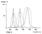
- the phosphors in the potting compound 24 are preferably selected such that the respective light spectrum emitted by them has the largest possible overlap range with transmission curves (FIG. FIG. 3 ) has the color filter.
- FIG. 3 the transmission curve of the blue filter 30 shown by a dashed line
- the green filter 32 is a dash-dot line
- the red filter 24 a dash-double-dot line.
- the spectra of the radiated light of the blue light emitting diode 22 and the phosphors are centered in the corresponding transmission curves of the color filters.
- the area enclosed by the spectral curves of the phosphors and the light-emitting diode 22 preferably has the largest possible overlapping area with the corresponding areas enclosed by the transmission curves. This allows a particularly good light output and a particularly good image representation in a particularly large color range. This contributes to a particularly good representation of an image by means of the monitor 2.
- the use of the light emitting diode 22 with the phosphors for the backlight 8 is particularly simple and inexpensive, since for each pixel only one light emitting diode must be controlled.
- the phosphors can be individually tailored to different color filters. "If possible, "large” may mean that the enclosed areas have an overlap area that has an area of at least 50% of the total area of the areas enclosed by the two spectral curves, preferably at least 75% of the total area.
Landscapes
- Physics & Mathematics (AREA)
- Nonlinear Science (AREA)
- Mathematical Physics (AREA)
- Chemical & Material Sciences (AREA)
- Crystallography & Structural Chemistry (AREA)
- General Physics & Mathematics (AREA)
- Optics & Photonics (AREA)
- Liquid Crystal (AREA)
- Devices For Indicating Variable Information By Combining Individual Elements (AREA)
- Led Device Packages (AREA)
- Planar Illumination Modules (AREA)
Description
- Die Erfindung betrifft eine Anzeigevorrichtung. Weiter betrifft die Erfindung eine Hintergrundbeleuchtungseinheit für eine Hintergrundbeleuchtung eines Bildschirms. Ferner betrifft die Erfindung eine Bildschirmeinheit des Bildschirms.
- Als Hintergrundbeleuchtung für eine Anzeigevorrichtung, wie zum Beispiel einen Monitor oder einen Bildschirm, beispielsweise einen LCD-Bildschirm, werden regelmäßig Kaltkathodenröhren verwendet, die weißes Licht abstrahlen. Bei diesen Kaltkathodenröhren entsteht das Licht durch eine kalte Entladung von Quecksilber und Gasen. Zur Farbdarstellung auf dem Bildschirm wird das Licht der Hintergrundbeleuchtung durch Farbfilter gefiltert.
- Die Druckschrift
EP 1 566 848 A beschreibt eine Anzeigevorrichtung. - Die Aufgabe, die der Erfindung zugrunde liegt, ist, eine Anzeigevorrichtung zu schaffen, die einfach und günstig eine besonders gute Bilddarstellung ermöglichen.
- Die Aufgabe wird durch eine Anzeigevorrichtung gemäß Anspruch 1 gelöst.
- Gemäß einem ersten Aspekt einer Ausgestaltung der Erfindung ist eine Hintergrundbeleuchtungseinheit für eine Hintergrundbeleuchtung einer Anzeigevorrichtung, insbesondere eines Bildschirms oder einer Bildschirmeinheit, vorgesehen.
- Der Ausdruck "Bildschirm" ist dabei nicht auf den Bildschirm eines Monitors oder eines TV-Geräts beschränkt. Es kann sich zum Beispiel auch um eine großflächige Anzeigevorrichtung handeln, die einen Flächeninhalt von 10 m2 oder mehr aufweist.
- Die Hintergrundbeleuchtungseinheit hat eine blaues Licht emittierende Leuchtdiode und grün und rot emittierende Phosphore, die so angeordnet und ausgebildet sind, dass das blaue Licht der Leuchtdiode die grün und rot emittierenden Phosphore anregt.
- Dies ermöglicht besonders einfach und günstig eine besonders gute Darstellung mittels des Bildschirms, da pro Bildpunkt des Bildschirms lediglich eine Leuchtdiode vorgesehen sein muss und da ein besonders breites Farbspektrum darstellbar ist.
- Gemäß einem zweiten Aspekt einer Ausgestaltung der Erfindung ist die Hintergrundbeleuchtungseinheit für die Hintergrundbeleuchtung der Anzeigevorrichtung, zum Beispiel des Bildschirms, vorgesehen. Die Hintergrundbeleuchtungseinheit hat die blaues Licht emittierende Leuchtdiode und grün und gelb emittierende Phosphore, die so angeordnet und ausgebildet sind, dass das blaue Licht der Leuchtdiode die grün und gelb emittierenden Phosphore anregt. Dies ermöglicht besonders einfach und günstig eine besonders gute Bilddarstellung mittels des Bildschirms, da pro Bildpunkt des Bildschirms lediglich die eine Leuchtdiode vorgesehen sein muss und da ein besonders breites Farbspektrum darstellbar ist.
- Die grünes Licht emittierenden Phosphore sind beispielsweise aus der Gruppe der seltenerd-dotierten Granate, Silikate, Scandanate, Thiogallate und/oder Oxynitride. Die rotes Licht emittierenden Phosphore sind beispielsweise aus der Gruppe der seltenerd-dotierten Silikate, Oxynitride, Nitride, Sulfide.
- Gemäß einem dritten Aspekt einer Ausgestaltung der Erfindung ist eine Bildschirmeinheit des Bildschirms vorgesehen. Die Bildschirmeinheit umfasst die Hintergrundbeleuchtungseinheit. Ferner umfasst die Bildschirmeinheit einen
Polarisationsfilter, der in einer Abstrahlrichtung der Hintergrundbeleuchtungseinheit angeordnet ist und der die Hintergrundbeleuchtungseinheit zumindest teilweise überdeckt. Eine Flüssigkristallschicht ist auf der von der Hintergrundbeleuchtungseinheit abgewandten Seite des Polarisationsfilters angeordnet. Eine Filteranordnung umfasst zumindest einen Farbfilter und ist auf der von der Hintergrundbeleuchtungseinheit abgewandten Seite der Flüssigkristallschicht angeordnet. - Gemäß einem vierten Aspekt wird eine Anzeigevorrichtung, insbesondere eine Bildschirmeinheit eines Bildschirms angegeben, mit
- einer Hintergrundbeleuchtungseinheit für eine Hintergrundbeleuchtung des Bildschirms,
- einem Polarisationsfilter, der in einer Abstrahlrichtung der Hintergrundbeleuchtungseinheit angeordnet ist und der die Hintergrundbeleuchtungseinheit zumindest teilweise überdeckt,
- einer Flüssigkristallschicht, die auf der von der Hintergrundbeleuchtungseinheit abgewandten Seite des Polarisationsfilters angeordnet ist, und
- einer Filteranordnung, die zumindest einen Farbfilter umfasst und die auf der von der Hintergrundbeleuchtungseinheit abgewandten Seite der Flüssigkristallschicht angeordnet ist, wobei
- die Hintergrundbeleuchtungseinheit eine blaues Licht emittierende Leuchtdiode umfasst, und wobei
- der blaues Licht emittierenden Leuchtdiode zumindest zwei unterschiedliche Phosphoren nachgeordnet sind, die das blaue Licht der Leuchtdiode absorbieren und Licht voneinander unterschiedlicher Farbe re-emittieren, das sich mit dem blauen Licht der Leuchtdiode (22) zu weißem Licht mischt.
- In einer Ausgestaltung sind die Phosphore der Hintergrundbeleuchtungseinheit so ausgebildet, dass Spektralkurven der Phosphore einen möglichst großen Überlappungsbereich mit den Transmissionskurven des Farbfilters aufweisen. Dies trägt besonders wirkungsvoll zu der besonders guten Darstellung mittels des Bildschirms bei.
- In einer weiteren Ausgestaltung weist die Bildschirmeinheit für jeden Bildpunkt der Bildschirmeinheit jeweils drei unterschiedliche Farbfilter und Leuchtdioden lediglich eine Hintergrundbeleuchtungseinheit auf. Dies ermöglicht besonders einfach die einfache und günstige Ausgestaltung der Bildschirmeinheit.
- Ausführungsbeispiele der Erfindung sind im Folgenden anhand von schematischen Zeichnungen näher erläutert.
- Es zeigen:
- Figur 1
- einen Monitor,
- Figur 2
- einen Querschnitt durch einen Bildpunkt einer Bildschirmeinheit des Monitors,
- Figur 3
- Transmissionskurven der Farbfilter und der Hintergrundbeleuchtungseinheit.
- Gleiche, gleichartige oder gleich wirkende Elemente sind in den Figuren mit denselben Bezugszeichen versehen. Die Figuren und die Größenverhältnisse der in den Figuren dargestellten Elemente untereinander sind nicht als maßstäblich zu betrachten. Vielmehr können einzelne Elemente zur besseren Darstellbarkeit und/oder zum besseren Verständnis übertrieben groß dargestellt sein.
- Ein Monitor 2 (
Figur 1 ) umfasst einen Bildschirm 4. Der Bildschirm 4 kann einstückig hergestellt sein und lediglich eine Bildschirmeinheit 6 umfassen. Alternativ dazu kann der Bildschirm mehrstückig hergestellt sein und mehrere Bildschirmeinheiten 6 umfassen. Je eine der Bildschirmeinheiten 6 umfasst einen oder mehrere Bildpunkte des Bildschirms 4. Der Monitor 2 ist beispielsweise ein LCD-Monitor oder ein LCD-Fernseher. - Je ein Bildpunkt des Bildschirms 4 (
Figur 2 ) umfasst eine Hintergrundbeleuchtungseinheit 8, einen ersten Polarisationsfilter 10, eine erste Glasplatte 12, eine Flüssigkristallschicht 14, eine Filterschicht 16, eine zweite Glasplatte 18 und einen zweiten Polarisationsfilter 20. - Die Hintergrundbeleuchtungseinheit 8 umfasst eine blaues Licht emittierende Leuchtdiode 22. Die blaues Licht emittierende Leuchtdiode 22 ist in einer Vergussmasse 24 eingebettet. Die Vergussmasse 24 umfasst Phosphore. Die Phosphore werden durch das blaue Licht der Leuchtdiode 22 angeregt. Die angeregten Phosphore emittieren teilweise grünes und teilweise rotes Licht. Alternativ dazu emittieren die Phosphore grünes und gelbes Licht. Das bedeutet in diesem Zusammenhang, dass zumindest zwei unterschiedliche Arten von Phosphoren in der Vergussmasse 24 eingebettet sind und dass diese jeweils anders farbiges Licht emittieren. Die Leuchtdiode 22 und die Phosphore sind so ausgebildet und angeordnet, dass sich das blaue Licht der Leuchtdiode 22 und das grüne und rote oder grüne und gelbe Licht der Phosphore zu weißem Licht 36 mischt, das dann von der Hintergrundbeleuchtungseinheit 8 abgestrahlt wird.
- Die Hintergrundbeleuchtungseinheit 8 kann eine Abdeckung 26 aufweisen. In Abstrahlrichtung der Hintergrundbeleuchtungseinheit folgt auf die Abdeckung 26 der ersten Polarisationsfilter 10. Der erste Polarisationsfilter 10 ist vorgesehen zum Filtern des von der Leuchtdiode 22 abgestrahlten Lichts. Das polarisierte Licht durchdringt die erste Glasplatte 12, die zusammen mit der zweiten Glasplatte 18 die Flüssigkristallschicht 14 und die Filterschicht 16 einbettet. Die Flüssigkristallschicht 14 ist mit Elektroden 28 gekoppelt. Abhängig von einer Spannung, die an den Elektroden 28 anliegt, werden die Kristalle der Flüssigkristallschicht 14 zwischen den entsprechenden Elektroden ausgerichtet, so dass davon abhängig das von der Hintergrundbeleuchtung 8 abgestrahlte Licht nahezu ungehindert die Flüssigkristallschicht 14 passieren kann oder entsprechend abgeschwächt wird.
- Die Filterschicht 16 weist vorzugsweise einen blauen Filter 30, einen grünen Filter 32 und einen roten Filter 34 auf. Abhängig von der Spannung an den Elektroden wird somit in Abstrahlungsrichtung hinter dem entsprechenden Filter unterschiedlich starkes blaues, grünes oder rotes Licht 38, 40, 42 durchgelassen. Das blaue, grüne und rote Licht 38, 40 42 kann somit abhängig von der Spannung an den entsprechenden Elektroden unterschiedlich gemischt werden, was das Darstellen einer breiten Farbpalette ermöglicht. Die zweite Glasplatte kann mit dem zweiten Polarisationsfilter 20 abgedeckt sein.
- Die Phosphore in der Vergussmasse 24 sind vorzugsweise so gewählt, dass das jeweils von ihnen abgestrahlte Lichtspektrum einen möglichst großen Überlappungsbereich mit Transmissionskurven (
Figur 3 ) der Farbfilter aufweist. Beispielsweise wird inFigur 3 die Transmissionskurve des blauen Filters 30 durch eine gestrichelte Linie dargestellt, die des grünen Filters 32 eine Strichpunkt-Linie und die des roten Filters 24 eine Strich-Doppelpunkt-Linie. Die Spektren des abgestrahlten Lichts der blaues Licht emittierenden Leuchtdiode 22 und der Phosphore liegen mittig in den entsprechenden Transmissionskurven der Farbfilter. Vorzugsweise weist die von den Spektralkurven der Phosphore und der Leuchtdiode 22 eingeschlossene Fläche einen möglichst großen Überlappungsbereich mit den entsprechenden von den Transmissionskurven eingeschlossenen Flächen auf. Dies ermöglicht eine besonders gute Lichtausbeute und eine besonders gute Bilddarstellung in einem besonders großen Farbbereich. Dies trägt zu einer besonders guten Darstellung eines Bildes mittels des Monitors 2 bei. Ferner ist die Verwendung der Leuchtdiode 22 mit den Phosphoren für die Hintergrundbeleuchtung 8 besonders einfach und günstig, da für jeden Bildpunkt lediglich eine Leuchtdiode angesteuert werden muss. Ferner können die Phosphore individuell auf unterschiedliche Farbfilter ängepasst werden. "Möglichst groß" kann dabei heißen, dass die eingeschlossenen Flächen einen Überlappbereich aufweisen, der einen Flächeninhalt von wenigstens 50 % des Gesamtflächeninhalts der von den beiden Spektralkurven eingeschlossenen Flächen aufweist. Bevorzugt beträgt der Anteil wenigstens 75 % des Gesamtflächeninhalts.
Claims (6)
- Anzeigevorrichtung, insbesondere Bildschirmeinheit (6) eines Bildschirms (4), mit- zumindest einer Hintergrundbeleuchtungseinheit (8) für eine Hintergrundbeleuchtung des Bildschirms (4),- einem Polarisationsfilter (10), der in einer Abstrahlrichtung der Hintergrundbeleuchtungseinheit (8) angeordnet ist und der die Hintergrundbeleuchtungseinheit (8) zumindest teilweise überdeckt,- einer Flüssigkristallschicht (14), die auf der von der Hintergrundbeleuchtungseinheit (8) abgewandten Seite des Polarisationsfilters (10) angeordnet ist, und- einer Filteranordnung (16), die zumindest einen Farbfilter umfasst und die auf der von der Hintergrundbeleuchtungseinheit (8) abgewandten Seite der Flüssigkristallschicht (14) angeordnet ist, wobei- die Hintergrundbeleuchtungseinheit (8) eine blaues Licht emittierende Leuchtdiode (22) umfasst, und wobei- der blaues Licht emittierenden Leuchtdiode (22) in ihrer Abstrahlrichtung zumindest zwei unterschiedliche Phosphore nachgeordnet sind, die das blaue Licht der Leuchtdiode (22) absorbieren und Licht voneinander unterschiedlicher Farbe re-emittieren, das sich mit dem blauen Licht der Leuchtdiode (22) zu weißem Licht (36) mischt, und- die blaues Licht emittierende Leuchtdiode (22) in einer Vergussmasse (24) eingebettet ist, welche die Phosphore umfasst, dadurch gekennzeichnet, dass- die Phosphore der Hintergrundbeleuchtungseinheit (8) so ausgebildet sind, dass Spektralkurven der Phosphore einen Überlappungsbereich von wenigstens 50% des Gesamtflächeninhalts der von den Spektralkurven der Phosphore eingeschlossenen Fläche mit den Transmissionskurven des Farbfilters aufweisen.
- Anzeigevorrichtung nach dem vorherigen Anspruch,
bei der der blaues Licht emittierenden Leuchtdiode (22) grün und rot re-emittierende Phosphore nachgeordnet sind. - Anzeigevorrichtung nach Anspruch 1,
bei der der blaues Licht emittierenden Leuchtdiode (22) grün und gelb re-emittierende Phosphore nachgeordnet sind. - Anzeigevorrichtung nach Anspruch 1,
bei der der blaues Licht emittierenden Leuchtdiode (22) grün, rot und gelb re-emittierende Phosphore nachgeordnet sind. - Anzeigevorrichtung nach einem der vorherigen Ansprüche mit- einer Vielzahl von Bildpunkten, wobei- jeder Bildpunkt der Bildschirmeinheit (6) jeweils drei unterschiedliche Farbfilter und lediglich eine einzige Hintergrundbeleuchtungseinheit (8) aufweist.
- Anzeigevorrichtung nach einem der vorherigen Ansprüche mit- einer Vielzahl von Bildpunkten, wobei- jedem Bildpunkt eine blaues Licht emittierende Leuchtdiode (22) eineindeutig zugeordnet ist.
Applications Claiming Priority (2)
| Application Number | Priority Date | Filing Date | Title |
|---|---|---|---|
| DE102008006990A DE102008006990A1 (de) | 2008-01-31 | 2008-01-31 | Hintergrundbeleuchtungseinheit für eine Hintergrundbeleuchtung eines Bildschirms und Bildschirmeinheit des Bildschirms |
| PCT/DE2009/000102 WO2009094993A1 (de) | 2008-01-31 | 2009-01-26 | Anzeigevorrichtung |
Publications (2)
| Publication Number | Publication Date |
|---|---|
| EP2240821A1 EP2240821A1 (de) | 2010-10-20 |
| EP2240821B1 true EP2240821B1 (de) | 2016-08-31 |
Family
ID=40568790
Family Applications (1)
| Application Number | Title | Priority Date | Filing Date |
|---|---|---|---|
| EP09706913.2A Active EP2240821B1 (de) | 2008-01-31 | 2009-01-26 | Anzeigevorrichtung |
Country Status (7)
| Country | Link |
|---|---|
| US (1) | US20110205146A1 (de) |
| EP (1) | EP2240821B1 (de) |
| JP (1) | JP2011511960A (de) |
| KR (1) | KR20100118127A (de) |
| CN (1) | CN101932969B (de) |
| DE (1) | DE102008006990A1 (de) |
| WO (1) | WO2009094993A1 (de) |
Families Citing this family (2)
| Publication number | Priority date | Publication date | Assignee | Title |
|---|---|---|---|---|
| US10240195B2 (en) * | 2014-03-24 | 2019-03-26 | The Trustees Of Columbia University In The City Of New York | Chemical methods for producing tagged nucleotides |
| CN105742329A (zh) * | 2016-03-07 | 2016-07-06 | 京东方科技集团股份有限公司 | 显示面板及其制造方法和显示装置 |
Citations (2)
| Publication number | Priority date | Publication date | Assignee | Title |
|---|---|---|---|---|
| US6351069B1 (en) * | 1999-02-18 | 2002-02-26 | Lumileds Lighting, U.S., Llc | Red-deficiency-compensating phosphor LED |
| EP1521235A2 (de) * | 2003-10-03 | 2005-04-06 | LumiLeds Lighting U.S., LLC | Flüssigkristallanzeigenrückbeleuchtung mit einem zweidimensionalen Feld von Leuchtdioden |
Family Cites Families (24)
| Publication number | Priority date | Publication date | Assignee | Title |
|---|---|---|---|---|
| DE19638667C2 (de) * | 1996-09-20 | 2001-05-17 | Osram Opto Semiconductors Gmbh | Mischfarbiges Licht abstrahlendes Halbleiterbauelement mit Lumineszenzkonversionselement |
| DE19845229C1 (de) * | 1998-10-01 | 2000-03-09 | Wustlich Daniel | Mit Weißlicht arbeitende Hintergrundbeleuchtung |
| US6680569B2 (en) * | 1999-02-18 | 2004-01-20 | Lumileds Lighting U.S. Llc | Red-deficiency compensating phosphor light emitting device |
| JP4491948B2 (ja) * | 2000-10-06 | 2010-06-30 | ソニー株式会社 | 素子実装方法および画像表示装置の製造方法 |
| TW541722B (en) * | 2001-04-20 | 2003-07-11 | Nichia Corp | Light emitting device |
| EP2017901A1 (de) * | 2001-09-03 | 2009-01-21 | Panasonic Corporation | Lichtemittierende Halbleitervorrichtung, Lichtemittierendes Gerät und Herstellungsverfahren für eine lichtemittierende Halbleitervorrichtung |
| JP2007235184A (ja) * | 2001-09-03 | 2007-09-13 | Matsushita Electric Ind Co Ltd | 半導体発光デバイス |
| US20040120140A1 (en) * | 2002-03-27 | 2004-06-24 | Fye Michael E. | Illuminated graphics using fluorescing materials |
| US6975369B1 (en) * | 2002-12-12 | 2005-12-13 | Gelcore, Llc | Liquid crystal display with color backlighting employing light emitting diodes |
| JP2005173309A (ja) * | 2003-12-12 | 2005-06-30 | Matsushita Electric Ind Co Ltd | 表示装置 |
| US7250715B2 (en) | 2004-02-23 | 2007-07-31 | Philips Lumileds Lighting Company, Llc | Wavelength converted semiconductor light emitting devices |
| US8417215B2 (en) * | 2004-07-28 | 2013-04-09 | Koninklijke Philips Electronics N.V. | Method for positioning of wireless medical devices with short-range radio frequency technology |
| US7575697B2 (en) * | 2004-08-04 | 2009-08-18 | Intematix Corporation | Silicate-based green phosphors |
| US7220040B2 (en) * | 2004-11-12 | 2007-05-22 | Harris Corporation | LED light engine for backlighting a liquid crystal display |
| US7796179B2 (en) * | 2005-02-03 | 2010-09-14 | Nikon Corporation | Display device, electronic apparatus and camera |
| EP1865564B1 (de) * | 2005-03-18 | 2014-11-19 | Mitsubishi Chemical Corporation | Licht emittierendes bauelement, weisses licht emittierendes bauelement, illuminator und bildanzeige |
| JP5098221B2 (ja) * | 2005-05-24 | 2012-12-12 | 三菱化学株式会社 | 発光装置、照明装置、ディスプレイ用バックライトおよびディスプレイ |
| JP4438761B2 (ja) * | 2006-03-09 | 2010-03-24 | ソニー株式会社 | 発光組成物及び光源装置 |
| EP2009486A4 (de) * | 2006-04-19 | 2009-12-09 | Mitsubishi Chem Corp | Farbbildanzeigeeinrichtung |
| KR100809263B1 (ko) * | 2006-07-10 | 2008-02-29 | 삼성전기주식회사 | 직하 방식 백라이트 장치 |
| GB2442505A (en) * | 2006-10-04 | 2008-04-09 | Sharp Kk | A display with a primary light source for illuminating a nanophosphor re-emission material |
| JP3129119U (ja) * | 2006-10-16 | 2007-02-08 | 玄基光電半導體股▲ふん▼有限公司 | 植え込み式ledを有するバックライト・パネルの構造 |
| JP2008122681A (ja) * | 2006-11-13 | 2008-05-29 | Sony Corp | 物品の実装方法、発光ダイオード表示装置の製造方法、及び、物品中間物の仮固定用基板への仮固定方法 |
| US20090051637A1 (en) * | 2007-08-20 | 2009-02-26 | Himax Technologies Limited | Display devices |
-
2008
- 2008-01-31 DE DE102008006990A patent/DE102008006990A1/de not_active Withdrawn
-
2009
- 2009-01-26 KR KR1020107019144A patent/KR20100118127A/ko not_active Ceased
- 2009-01-26 JP JP2010544578A patent/JP2011511960A/ja active Pending
- 2009-01-26 EP EP09706913.2A patent/EP2240821B1/de active Active
- 2009-01-26 US US12/865,847 patent/US20110205146A1/en not_active Abandoned
- 2009-01-26 CN CN2009801037481A patent/CN101932969B/zh active Active
- 2009-01-26 WO PCT/DE2009/000102 patent/WO2009094993A1/de not_active Ceased
Patent Citations (2)
| Publication number | Priority date | Publication date | Assignee | Title |
|---|---|---|---|---|
| US6351069B1 (en) * | 1999-02-18 | 2002-02-26 | Lumileds Lighting, U.S., Llc | Red-deficiency-compensating phosphor LED |
| EP1521235A2 (de) * | 2003-10-03 | 2005-04-06 | LumiLeds Lighting U.S., LLC | Flüssigkristallanzeigenrückbeleuchtung mit einem zweidimensionalen Feld von Leuchtdioden |
Also Published As
| Publication number | Publication date |
|---|---|
| WO2009094993A1 (de) | 2009-08-06 |
| CN101932969A (zh) | 2010-12-29 |
| EP2240821A1 (de) | 2010-10-20 |
| DE102008006990A1 (de) | 2009-08-06 |
| JP2011511960A (ja) | 2011-04-14 |
| US20110205146A1 (en) | 2011-08-25 |
| CN101932969B (zh) | 2012-05-23 |
| KR20100118127A (ko) | 2010-11-04 |
Similar Documents
| Publication | Publication Date | Title |
|---|---|---|
| EP1282171B1 (de) | Planare Lichtquelle auf LED-Basis | |
| DE102006030890B4 (de) | System und Verfahren zum Erzeugen von weißem Licht unter Verwendung einer Kombination von weißen Leuchtstoffumwandlungs-LEDs und Nicht-Leuchtstoffumwandlung-Farb-LEDs | |
| EP3319073B1 (de) | Anzeige | |
| DE102005001685A1 (de) | System und Verfahren zum Erzeugen weißen Lichts unter Verwendung von LEDs | |
| DE112006000813T5 (de) | LED-Backlight-System für eine Flachbildanzeige (typischerweise LCD), bei der die Anzahl von verschiedenen Farben der LEDs grösser als die Anzahl von verschiedenen Pixelfarben ist | |
| WO2004032235A2 (de) | Einrichtung zur erzeugung eines gebündelten lichtstromes | |
| DE10335077A1 (de) | LED-Modul | |
| EP1924883A2 (de) | Hinterleuchtungsanordnung mit in leuchtgruppen angeordneten halbleiterlichtquellen und leuchtvorrichtung | |
| DE102006009955A1 (de) | Lichtaussendende Einrichtung und Beleuchtungsvorrichtung, die die lichtaussendende Einrichtung verwendet | |
| DE10319274A1 (de) | Lichtquelle | |
| DE202008018053U1 (de) | Mit Weisslicht-Leuchtdioden arbeitende Oberflächenlichtquelle und Flüssigkristallanzeige-Hinterleuchtungseinheit mit einer solchen Oberflächenlichtquelle | |
| DE102012106456A1 (de) | Eine weißes Licht aussendende Vorrichtung, sowie Anzeigegerät und Beleuchtungsgerät, die diese nutzen | |
| JP5878580B2 (ja) | 表示装置及びテレビ受信装置 | |
| DE10001188A1 (de) | Flüssigkristallfarbbildschirm mit Leuchtstoffschicht | |
| EP3163637B1 (de) | Weisses licht abstrahlendes led-modul | |
| EP2240821A1 (de) | Anzeigevorrichtung | |
| DE102015120775B4 (de) | Optoelektronisches Bauelement und Hintergrundbeleuchtung für ein Display | |
| DE102012109104B4 (de) | Beleuchtungseinrichtung, Hinterleuchtung für ein Display oder einen Fernseher und Display oder Fernseher | |
| WO2018104395A1 (de) | Optoelektronisches bauelement | |
| DE102010041236A1 (de) | Optoelektronisches Halbleiterbauelement | |
| WO2013041314A1 (de) | Optoelektronisches halbleiterbauelement und modul mit einer mehrzahl von derartigen bauelementen | |
| DE102016123971A1 (de) | Optoelektronisches Bauelement | |
| WO2013004496A2 (de) | Optoelektronisches halbleiterbauelement und modul mit einer mehrzahl von derartigen bauelementen | |
| EP3284113B1 (de) | Verfahren zur herstellung eines led-modul zur abgabe von weisslicht | |
| EP1452903B1 (de) | Flüssigkristallanzeige |
Legal Events
| Date | Code | Title | Description |
|---|---|---|---|
| PUAI | Public reference made under article 153(3) epc to a published international application that has entered the european phase |
Free format text: ORIGINAL CODE: 0009012 |
|
| 17P | Request for examination filed |
Effective date: 20100805 |
|
| AK | Designated contracting states |
Kind code of ref document: A1 Designated state(s): AT BE BG CH CY CZ DE DK EE ES FI FR GB GR HR HU IE IS IT LI LT LU LV MC MK MT NL NO PL PT RO SE SI SK TR |
|
| AX | Request for extension of the european patent |
Extension state: AL BA RS |
|
| RIN1 | Information on inventor provided before grant (corrected) |
Inventor name: WINTER, MATTHIAS Inventor name: KROMOTIS, PATRICK |
|
| DAX | Request for extension of the european patent (deleted) | ||
| 17Q | First examination report despatched |
Effective date: 20111123 |
|
| REG | Reference to a national code |
Ref country code: DE Ref legal event code: R079 Ref document number: 502009013017 Country of ref document: DE Free format text: PREVIOUS MAIN CLASS: G02F0001133570 Ipc: G02F0001133500 |
|
| GRAP | Despatch of communication of intention to grant a patent |
Free format text: ORIGINAL CODE: EPIDOSNIGR1 |
|
| INTG | Intention to grant announced |
Effective date: 20150206 |
|
| RIC1 | Information provided on ipc code assigned before grant |
Ipc: G02F 1/1335 20060101AFI20150127BHEP |
|
| GRAP | Despatch of communication of intention to grant a patent |
Free format text: ORIGINAL CODE: EPIDOSNIGR1 |
|
| INTG | Intention to grant announced |
Effective date: 20160324 |
|
| GRAS | Grant fee paid |
Free format text: ORIGINAL CODE: EPIDOSNIGR3 |
|
| GRAA | (expected) grant |
Free format text: ORIGINAL CODE: 0009210 |
|
| AK | Designated contracting states |
Kind code of ref document: B1 Designated state(s): AT BE BG CH CY CZ DE DK EE ES FI FR GB GR HR HU IE IS IT LI LT LU LV MC MK MT NL NO PL PT RO SE SI SK TR |
|
| REG | Reference to a national code |
Ref country code: CH Ref legal event code: EP Ref country code: GB Ref legal event code: FG4D Free format text: NOT ENGLISH |
|
| REG | Reference to a national code |
Ref country code: IE Ref legal event code: FG4D Free format text: LANGUAGE OF EP DOCUMENT: GERMAN |
|
| REG | Reference to a national code |
Ref country code: DE Ref legal event code: R096 Ref document number: 502009013017 Country of ref document: DE |
|
| REG | Reference to a national code |
Ref country code: AT Ref legal event code: REF Ref document number: 825478 Country of ref document: AT Kind code of ref document: T Effective date: 20161015 |
|
| REG | Reference to a national code |
Ref country code: LT Ref legal event code: MG4D |
|
| REG | Reference to a national code |
Ref country code: NL Ref legal event code: MP Effective date: 20160831 |
|
| PG25 | Lapsed in a contracting state [announced via postgrant information from national office to epo] |
Ref country code: LT Free format text: LAPSE BECAUSE OF FAILURE TO SUBMIT A TRANSLATION OF THE DESCRIPTION OR TO PAY THE FEE WITHIN THE PRESCRIBED TIME-LIMIT Effective date: 20160831 Ref country code: FI Free format text: LAPSE BECAUSE OF FAILURE TO SUBMIT A TRANSLATION OF THE DESCRIPTION OR TO PAY THE FEE WITHIN THE PRESCRIBED TIME-LIMIT Effective date: 20160831 Ref country code: HR Free format text: LAPSE BECAUSE OF FAILURE TO SUBMIT A TRANSLATION OF THE DESCRIPTION OR TO PAY THE FEE WITHIN THE PRESCRIBED TIME-LIMIT Effective date: 20160831 Ref country code: NO Free format text: LAPSE BECAUSE OF FAILURE TO SUBMIT A TRANSLATION OF THE DESCRIPTION OR TO PAY THE FEE WITHIN THE PRESCRIBED TIME-LIMIT Effective date: 20161130 |
|
| PG25 | Lapsed in a contracting state [announced via postgrant information from national office to epo] |
Ref country code: GR Free format text: LAPSE BECAUSE OF FAILURE TO SUBMIT A TRANSLATION OF THE DESCRIPTION OR TO PAY THE FEE WITHIN THE PRESCRIBED TIME-LIMIT Effective date: 20161201 Ref country code: SE Free format text: LAPSE BECAUSE OF FAILURE TO SUBMIT A TRANSLATION OF THE DESCRIPTION OR TO PAY THE FEE WITHIN THE PRESCRIBED TIME-LIMIT Effective date: 20160831 Ref country code: ES Free format text: LAPSE BECAUSE OF FAILURE TO SUBMIT A TRANSLATION OF THE DESCRIPTION OR TO PAY THE FEE WITHIN THE PRESCRIBED TIME-LIMIT Effective date: 20160831 Ref country code: LV Free format text: LAPSE BECAUSE OF FAILURE TO SUBMIT A TRANSLATION OF THE DESCRIPTION OR TO PAY THE FEE WITHIN THE PRESCRIBED TIME-LIMIT Effective date: 20160831 Ref country code: NL Free format text: LAPSE BECAUSE OF FAILURE TO SUBMIT A TRANSLATION OF THE DESCRIPTION OR TO PAY THE FEE WITHIN THE PRESCRIBED TIME-LIMIT Effective date: 20160831 |
|
| PG25 | Lapsed in a contracting state [announced via postgrant information from national office to epo] |
Ref country code: EE Free format text: LAPSE BECAUSE OF FAILURE TO SUBMIT A TRANSLATION OF THE DESCRIPTION OR TO PAY THE FEE WITHIN THE PRESCRIBED TIME-LIMIT Effective date: 20160831 Ref country code: RO Free format text: LAPSE BECAUSE OF FAILURE TO SUBMIT A TRANSLATION OF THE DESCRIPTION OR TO PAY THE FEE WITHIN THE PRESCRIBED TIME-LIMIT Effective date: 20160831 |
|
| PG25 | Lapsed in a contracting state [announced via postgrant information from national office to epo] |
Ref country code: SK Free format text: LAPSE BECAUSE OF FAILURE TO SUBMIT A TRANSLATION OF THE DESCRIPTION OR TO PAY THE FEE WITHIN THE PRESCRIBED TIME-LIMIT Effective date: 20160831 Ref country code: BG Free format text: LAPSE BECAUSE OF FAILURE TO SUBMIT A TRANSLATION OF THE DESCRIPTION OR TO PAY THE FEE WITHIN THE PRESCRIBED TIME-LIMIT Effective date: 20161130 Ref country code: PT Free format text: LAPSE BECAUSE OF FAILURE TO SUBMIT A TRANSLATION OF THE DESCRIPTION OR TO PAY THE FEE WITHIN THE PRESCRIBED TIME-LIMIT Effective date: 20170102 Ref country code: PL Free format text: LAPSE BECAUSE OF FAILURE TO SUBMIT A TRANSLATION OF THE DESCRIPTION OR TO PAY THE FEE WITHIN THE PRESCRIBED TIME-LIMIT Effective date: 20160831 Ref country code: BE Free format text: LAPSE BECAUSE OF NON-PAYMENT OF DUE FEES Effective date: 20170131 Ref country code: CZ Free format text: LAPSE BECAUSE OF FAILURE TO SUBMIT A TRANSLATION OF THE DESCRIPTION OR TO PAY THE FEE WITHIN THE PRESCRIBED TIME-LIMIT Effective date: 20160831 Ref country code: DK Free format text: LAPSE BECAUSE OF FAILURE TO SUBMIT A TRANSLATION OF THE DESCRIPTION OR TO PAY THE FEE WITHIN THE PRESCRIBED TIME-LIMIT Effective date: 20160831 |
|
| REG | Reference to a national code |
Ref country code: DE Ref legal event code: R097 Ref document number: 502009013017 Country of ref document: DE |
|
| PG25 | Lapsed in a contracting state [announced via postgrant information from national office to epo] |
Ref country code: IT Free format text: LAPSE BECAUSE OF FAILURE TO SUBMIT A TRANSLATION OF THE DESCRIPTION OR TO PAY THE FEE WITHIN THE PRESCRIBED TIME-LIMIT Effective date: 20160831 |
|
| PLBE | No opposition filed within time limit |
Free format text: ORIGINAL CODE: 0009261 |
|
| STAA | Information on the status of an ep patent application or granted ep patent |
Free format text: STATUS: NO OPPOSITION FILED WITHIN TIME LIMIT |
|
| 26N | No opposition filed |
Effective date: 20170601 |
|
| PG25 | Lapsed in a contracting state [announced via postgrant information from national office to epo] |
Ref country code: SI Free format text: LAPSE BECAUSE OF FAILURE TO SUBMIT A TRANSLATION OF THE DESCRIPTION OR TO PAY THE FEE WITHIN THE PRESCRIBED TIME-LIMIT Effective date: 20160831 |
|
| REG | Reference to a national code |
Ref country code: CH Ref legal event code: PL |
|
| GBPC | Gb: european patent ceased through non-payment of renewal fee |
Effective date: 20170126 |
|
| PG25 | Lapsed in a contracting state [announced via postgrant information from national office to epo] |
Ref country code: MC Free format text: LAPSE BECAUSE OF FAILURE TO SUBMIT A TRANSLATION OF THE DESCRIPTION OR TO PAY THE FEE WITHIN THE PRESCRIBED TIME-LIMIT Effective date: 20160831 |
|
| REG | Reference to a national code |
Ref country code: FR Ref legal event code: ST Effective date: 20170929 |
|
| PG25 | Lapsed in a contracting state [announced via postgrant information from national office to epo] |
Ref country code: FR Free format text: LAPSE BECAUSE OF NON-PAYMENT OF DUE FEES Effective date: 20170131 Ref country code: LI Free format text: LAPSE BECAUSE OF NON-PAYMENT OF DUE FEES Effective date: 20170131 Ref country code: CH Free format text: LAPSE BECAUSE OF NON-PAYMENT OF DUE FEES Effective date: 20170131 |
|
| REG | Reference to a national code |
Ref country code: IE Ref legal event code: MM4A |
|
| PG25 | Lapsed in a contracting state [announced via postgrant information from national office to epo] |
Ref country code: LU Free format text: LAPSE BECAUSE OF NON-PAYMENT OF DUE FEES Effective date: 20170126 Ref country code: GB Free format text: LAPSE BECAUSE OF NON-PAYMENT OF DUE FEES Effective date: 20170126 |
|
| REG | Reference to a national code |
Ref country code: BE Ref legal event code: MM Effective date: 20170131 |
|
| PG25 | Lapsed in a contracting state [announced via postgrant information from national office to epo] |
Ref country code: IE Free format text: LAPSE BECAUSE OF NON-PAYMENT OF DUE FEES Effective date: 20170126 |
|
| REG | Reference to a national code |
Ref country code: AT Ref legal event code: MM01 Ref document number: 825478 Country of ref document: AT Kind code of ref document: T Effective date: 20170126 |
|
| PG25 | Lapsed in a contracting state [announced via postgrant information from national office to epo] |
Ref country code: AT Free format text: LAPSE BECAUSE OF NON-PAYMENT OF DUE FEES Effective date: 20170126 |
|
| PG25 | Lapsed in a contracting state [announced via postgrant information from national office to epo] |
Ref country code: MT Free format text: LAPSE BECAUSE OF FAILURE TO SUBMIT A TRANSLATION OF THE DESCRIPTION OR TO PAY THE FEE WITHIN THE PRESCRIBED TIME-LIMIT Effective date: 20160831 |
|
| PG25 | Lapsed in a contracting state [announced via postgrant information from national office to epo] |
Ref country code: HU Free format text: LAPSE BECAUSE OF FAILURE TO SUBMIT A TRANSLATION OF THE DESCRIPTION OR TO PAY THE FEE WITHIN THE PRESCRIBED TIME-LIMIT; INVALID AB INITIO Effective date: 20090126 |
|
| PG25 | Lapsed in a contracting state [announced via postgrant information from national office to epo] |
Ref country code: CY Free format text: LAPSE BECAUSE OF NON-PAYMENT OF DUE FEES Effective date: 20160831 |
|
| PG25 | Lapsed in a contracting state [announced via postgrant information from national office to epo] |
Ref country code: MK Free format text: LAPSE BECAUSE OF FAILURE TO SUBMIT A TRANSLATION OF THE DESCRIPTION OR TO PAY THE FEE WITHIN THE PRESCRIBED TIME-LIMIT Effective date: 20160831 |
|
| PG25 | Lapsed in a contracting state [announced via postgrant information from national office to epo] |
Ref country code: TR Free format text: LAPSE BECAUSE OF FAILURE TO SUBMIT A TRANSLATION OF THE DESCRIPTION OR TO PAY THE FEE WITHIN THE PRESCRIBED TIME-LIMIT Effective date: 20160831 |
|
| PG25 | Lapsed in a contracting state [announced via postgrant information from national office to epo] |
Ref country code: IS Free format text: LAPSE BECAUSE OF FAILURE TO SUBMIT A TRANSLATION OF THE DESCRIPTION OR TO PAY THE FEE WITHIN THE PRESCRIBED TIME-LIMIT Effective date: 20161231 |
|
| P01 | Opt-out of the competence of the unified patent court (upc) registered |
Effective date: 20230825 |
|
| PGFP | Annual fee paid to national office [announced via postgrant information from national office to epo] |
Ref country code: DE Payment date: 20260121 Year of fee payment: 18 |