EP2240798B1 - System für adaptive neighborhood-filterung (anf) und verfahren für 3d-tof-kameras - Google Patents
System für adaptive neighborhood-filterung (anf) und verfahren für 3d-tof-kameras Download PDFInfo
- Publication number
- EP2240798B1 EP2240798B1 EP09705442.3A EP09705442A EP2240798B1 EP 2240798 B1 EP2240798 B1 EP 2240798B1 EP 09705442 A EP09705442 A EP 09705442A EP 2240798 B1 EP2240798 B1 EP 2240798B1
- Authority
- EP
- European Patent Office
- Prior art keywords
- pixels
- distance
- amplitude
- adjacent pixels
- distance information
- Prior art date
- Legal status (The legal status is an assumption and is not a legal conclusion. Google has not performed a legal analysis and makes no representation as to the accuracy of the status listed.)
- Active
Links
Images



Classifications
-
- G—PHYSICS
- G01—MEASURING; TESTING
- G01S—RADIO DIRECTION-FINDING; RADIO NAVIGATION; DETERMINING DISTANCE OR VELOCITY BY USE OF RADIO WAVES; LOCATING OR PRESENCE-DETECTING BY USE OF THE REFLECTION OR RERADIATION OF RADIO WAVES; ANALOGOUS ARRANGEMENTS USING OTHER WAVES
- G01S17/00—Systems using the reflection or reradiation of electromagnetic waves other than radio waves, e.g. lidar systems
- G01S17/88—Lidar systems specially adapted for specific applications
- G01S17/89—Lidar systems specially adapted for specific applications for mapping or imaging
- G01S17/894—Three-dimensional [3D] imaging with simultaneous measurement of time-of-flight at a two-dimensional [2D] array of receiver pixels, e.g. time-of-flight cameras or flash lidar
-
- G—PHYSICS
- G06—COMPUTING OR CALCULATING; COUNTING
- G06T—IMAGE DATA PROCESSING OR GENERATION, IN GENERAL
- G06T5/00—Image enhancement or restoration
- G06T5/70—Denoising; Smoothing
-
- G—PHYSICS
- G06—COMPUTING OR CALCULATING; COUNTING
- G06T—IMAGE DATA PROCESSING OR GENERATION, IN GENERAL
- G06T7/00—Image analysis
- G06T7/50—Depth or shape recovery
- G06T7/55—Depth or shape recovery from multiple images
Definitions
- Time of flight (TOF) sensors typically utilize charge-coupled device (CCD) or complementary metal oxide semiconductor (CMOS) based technologies that are able to sample at high speed.
- CCD charge-coupled device
- CMOS complementary metal oxide semiconductor
- the typical application is for point distance sensing or three-dimensional (3D) imaging in which the scene of interest is actively illuminated with modulated illuminating radiation and the sensor sampling is performed synchronously with the modulation of the illuminating radiation.
- 3D three-dimensional
- German patent application DE19821974A1 (Schwarte, Vorplatz und Anlagen für für Ü Kunststoff Kunststoff Kunststoff Kunststoff Wellen, 1999), see also US Pat. No. 6,825,455 B1 , disclosed a photon-mixing element for a TOF sensor in which the switches that are used to transfer the charge carriers to the integration gates are controlled based on the modulation used for the illumination signal.
- a photon-mixing element for a TOF sensor in which the switches that are used to transfer the charge carriers to the integration gates are controlled based on the modulation used for the illumination signal.
- a combined structure of stripe-like elements, each of them with short transport paths is proposed. Nevertheless, the stripe-like structure leads to a poor fill-factor because the regions between the stripes are not photo-sensitive.
- WO 2007/045108 A1 presents a newer TOF sensor example.
- the drift field over most or all of the photosensitive area is basically static in time.
- the static or quasi static field in the photosensitive region moves or dumps the charge carriers into a typically smaller modulated region, which may or may not be photosensitive.
- the charge carriers are then swept from the modulated region into integration regions or gates synchronously with the modulated signal.
- This newer system can operate at much higher frequencies because demodulation is over a much smaller area, having a lower intrinsic capacitance, whereas transport within the large photosensitive region can be optimized for speed.
- the newer demodulation device avoids the trade-off between the sensitivity/fill-factor and the demodulation speed. Both aspects can be optimized in the pixel at the same time using this technology.
- a second step all of the non-aggregated pixels that were inspected instep one and all the values lying closer to a seed value than twice the noise standard deviation are also aggregated.
- the filtered value of the seed pixel is computed by averaging the values of pixels aggregated in the seed's adaptive neighborhood.
- amplitude-based distance image correction is only applied to dark pixels. There is no averaging of distance information.
- US 5,644,386 discloses a visual recognition system for detecting a target within a scene.
- a LADAR system is used for scanning laser light signals across the scene having the target to be characterized. Laser light reflected from the target is detected and processed into a three-dimensional image. The three-dimensional image is segmented to separate the target from the overall scene.
- a preprocessing of the signals can be carried out. The preprocessing may include using a median filter in which the range value is replaced by the median of the pixels in a sub-window centered about the pixel.
- An intensity guided median filter can be employed in which range pixels whose intensity falls above a threshold are used in a filter, and range pixels whose intensity falls below a threshold are replaced by the median of the pixels in the sub-window centered about the pixel.
- the invention features a method for filtering distance information from a 3D-measurement camera system.
- the method comprises comparing amplitude and/or distance information for pixels to adjacent pixels and averaging distance information for the pixels with the adjacent pixels when amplitude and/or distance information for the pixels is within a range of the amplitudes and/or distances for the adjacent pixels.
- the step of comparing comprises comparing the amplitude for pixels to adjacent pixels; and the step of averaging distance information for pixels comprises averaging the distance of pixels with the distance of adjacent pixels when the amplitude information for the pixels is within a range of the amplitudes for the adjacent pixels.
- the step of comparing comprises comparing the distance for pixels to adjacent pixels; and the step of averaging distance information for pixels comprises averaging the distance of pixels with the distance of adjacent pixels when the distance information for the pixels is within a range of the distances for the adjacent pixels, where the range is determined by the amplitudes.
- Fig. 1 illustrates the basic principle of a 3D-measurement camera system.
- Modulated illumination light ML1 from an illumination module or light source IM is sent to the object OB of a scene.
- a fraction of the total optical power sent out is reflected to the camera 10 and detected by the 3D imaging sensor SN.
- the sensor SN comprises a two dimensional pixel matrix of demodulation pixels DP.
- Each pixel DP is capable of demodulating the impinging light signal.
- a control board CB regulates the timing of the camera 10.
- the phase values of all pixels correspond to the particular distance information of the corresponding point in the scene.
- the two-dimension gray scale image with the distance information is converted into a three-dimensional image by image processor IP. This can be displayed to a user via display D or used as a machine vision input.
- Either pulse intensity-modulated or continuously intensity-modulated light is sent out by the illumination module or light source IM, reflected by the object and detected by the sensor.
- the sensor With each pixel of the sensor being capable of demodulating the optical signal at the same time, the sensor is able to deliver 3D images in real-time, i.e., frame rates of up to 30 Hertz (Hz), or even more, are possible. In pulse operation the demodulation would deliver the time-of-flight directly.
- Figs. 2A and 2B show the relationship between signals for the case of continuous sinusoidal modulation and the signal sampling. Although this specific modulation scheme is highlighted in the following, the utilization of the pixel in 3D-imaging is not restricted to this particular scheme. Any other modulation scheme is applicable: e.g. pulse, rectangular, pseudo-noise or chirp modulation. Only the final extraction of the distance information is different.
- Fig. 2A shows both the modulated emitted illumination signal ES and received signal RS.
- the amplitude A, offset B of the received signal RS and phase P between both signals are unknown, but they can be unambiguously reconstructed with at least three samples of the received signal.
- BG represents the received signal part due to background light.
- a sampling with four samples per modulation period is depicted.
- Each sample is an integration of the electrical signal over a duration dt that is a predefined fraction of the modulation period.
- the photo-generated charges are accumulated over several modulation periods, in some embodiments.
- the conduction channels of the demodulation region By activating the conduction channels of the demodulation region alternately the photogenerated charge injected into the demodulation region and spread out below the complete gate structure, is forced to drift or diffuse to the specific storage site.
- the alternation of the channel activation is done synchronously with the sampling frequency.
- the electronic timing circuit employing for example a field programmable gate array (FPGA), generates the signals for the synchronous channel activation in the demodulation stage.
- FPGA field programmable gate array
- injected charge carriers are moved to the corresponding integration region.
- A BG
- two samples A0 and A1 of the modulation signal sampled at times that differ by half of the modulation period allow the calculation of the phase P and the amplitude A of a sinusoidal intensity modulated current injected into the sampling stage.
- the present invention is employed in these 3D measurement camera systems 10. It is termed adaptive neighborhood filter (ANF) and is used by the image processor IP to reduce the noise in distance by doing plausibility checks of the distance measurement or phase that is calculated for neighboring pixels of the two dimensional image sensor SN.
- AMF adaptive neighborhood filter
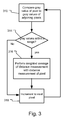
- Fig. 3 illustrates a first embodiment of the ANF in which the image processor IP steps through the responses of the demodulation pixels DP of the image sensor SN. If the neighboring pixels have similar amplitude or gray values, the probability that the pixels are in the same plane is deemed high. Hence, such pixels are spatially averaged in distance information with higher weight.
- the image processor compares the gray or amplitude value of a pixel to the gray or amplitude values of adjoining and/or adjacent pixels, in step 310.
- the pixels are characterized by a two dimensional array of n by m pixels in the image sensor.
- the processing begins with pixel (x 0 ,y 0 ) and ends with pixel (x n ,y m ).
- the gray value of pixel (x a ,y b ) is compared to the gray values of pixels (x a+1 ,y b ), (x a-1 ,y b ), (x a ,y b+1 ), and (x a ,y b-1 ).
- the distance information for pixel (x a ,y b ) is averaged with the adjacent pixels that are within the range in step 316.
- the distance information for pixel (x a ,y b ) is averaged with (x a+1 ,y b ), for example, if (absolute value [Gray value ⁇ (x a ,y b ) ⁇ -Gray value ⁇ (x a+1 ,y b ) ⁇ ] ) ⁇ r.
- the average is weighted average.
- step 318 the current pixel is incremented through each pixel in the row and then when the end of a row is reached to successive columns and the process repeats until the end of the array is reached at pixel pixel (x n ,y m ).
- Fig. 4 illustrates a second embodiment of the ANF in which the image processor IP steps through the responses of the demodulation pixels DP of the image sensor SN. If the neighboring pixels have similar distance values, the probability that the pixels are in the same plane is rather high. Hence, such pixels are spatially averaged with higher weight.
- the image processor compares the distance value of a pixel to the distance values of adjoining and/or adjacent pixels, in step 410.
- the distance value of pixel (x a ,y b ) is compared to the distance values of pixels (x a+1 ,y b ), (x a-1 ,y b ), (x a ,y b+1 ), and (x a ,y b-1 ).
- the distance information is averaged with the adjacent pixels that are within the range in step 416. Usually the average is weighted average here also.
- the range is selected in response to the gray value of the pixel in one example.
- each pixel is adaptively filtered based on its neighbors.
- the distance range allowed is defined as a dependence on the gray level it can be considered as whether a plausibility check is performed before averaging. Whether an average should be made strongly depends on the depth noise level, which is given by the gray level (amplitude) information. For example, if the pixel to be filtered (x a ,y b ) (reference pixel) shows 1 meter range or depth with a standard deviation of 5 millimeters, and its neighboring pixel (x i ,y j ) a distance of 1.1 meters then filtering is not desired (see Fig. 5A ).
- pixel (x a ,y b ) indicates 1 meter depth but with a standard deviation of 20 centimeters, then it makes sense to filter it with its neighboring filter (x i ,y j ) being at 1.1 meters ( Fig. 6B ).
- Weighting based on the range difference ⁇ z of the neighboring pixels and amplitude A (gray level): weight ⁇ ⁇ x a , y b ⁇ z ⁇ 1 A x a , x b ⁇ 1 ⁇ z with ⁇ z z x a . x b ⁇ z x i . y j
- weight ⁇ 1 ⁇ A with ⁇ A A x a , y b ⁇ A x i , y j
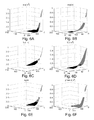
- Figs. 6A- 6F different weighting functions for performing a weighted average of the distance information with respect to distance information of adjacent pixels. For clarity only one quadrant of the weighting function is illustrated.
- Fig. 6A shows exp(-x 2 ) function
- Fig. 6B shows exp(-x) function
- Fig. 6C shows 1/(1+x) function
- Fig. 6D shows 1/(1+x 2 )
- Fig. 6E shows Taylor function
- Fig. 6F shows a power(2, x 2 ) function, which are used in different embodiments to perform a weighted average of the current pixel distance with respect to the distance from adjacent pixels.
Landscapes
- Engineering & Computer Science (AREA)
- Physics & Mathematics (AREA)
- General Physics & Mathematics (AREA)
- Theoretical Computer Science (AREA)
- Computer Vision & Pattern Recognition (AREA)
- Computer Networks & Wireless Communication (AREA)
- Electromagnetism (AREA)
- Radar, Positioning & Navigation (AREA)
- Remote Sensing (AREA)
- Optical Radar Systems And Details Thereof (AREA)
- Measurement Of Optical Distance (AREA)
Claims (8)
- Verfahren zum Filtern von Abstands-Information von einem Kamerasystem für 3D-Messungen (10), wobei das Verfahren umfasst:Vergleichen von Amplituden- oder Abstands-Information von Pixeln (DP) mit entsprechenden Amplituden- oder Abstands-Information von benachbarten Pixeln (DP); undMitteln von Abstands-Information für die Pixel (DP) mit der Abstands-Information der benachbarten Pixel (DP), wenn Amplituden- oder Abstands-Information für die Pixel (DP) innerhalb eines Bereichs der Amplituden oder Abstände für die benachbarten Pixel (DP) liegt.
- Verfahren wie in Anspruch 1 beansprucht, wobei der Schritt des Vergleichens Vergleichen der Amplitude für Pixel (DP) mit benachbarten Pixeln (DP) umfasst; und wobei der Schritt von Mitteln von Abstands-Information für die Pixel (DP) Mitteln des Abstands der Pixel (DP) mit dem Abstand der benachbarten Pixel (DP) umfasst, wenn die Amplituden-Information für die Pixel (DP) innerhalb eines Bereichs der Amplituden für die benachbarten Pixel (DP) liegt.
- Verfahren wie in Anspruch 1 beansprucht, wobei der Schritt des Vergleichens Vergleichen des Abstands für Pixel (DP) mit dem Abstand der benachbarten Pixel (DP) umfasst; und wobei der Schritt von Mitteln von Abstands-Information für die Pixel (DP) Mitteln des Abstands der Pixel (DP) mit dem Abstand der benachbarten Pixel (DP) umfasst, wenn die Abstands-Information für die Pixel (DP) innerhalb eines Bereichs der Abstände für die benachbarten Pixel (DP) liegt.
- Verfahren wie in Anspruch 1 beansprucht, wobei der Schritt des Mittelns in Antwort auf einen Rauschpegel des Abstandsmaßes für die Pixel (DP) und/oder Rauschpegel des Abstands für die benachbarten Pixel (DP) durchgeführt wird.
- Kamerasystem für 3D-Messungen (10), das umfasst:einen bildgebenden Time-of-Flight-Sensor, der eine zweidimensionale Anordnung von Pixeln (DP) umfasst, wobei jeder Amplituden- und Abstandsinformation erzeugt; undeinen Bildprozessor (IP), der die Amplituden- oder Abstands-Information von Pixeln (DP) mit entsprechenden Amplituden- oder Abstands-Information von benachbarten Pixeln (DP) vergleicht und Abstands-Information für die Pixel (DP) mit der Abstands-Information der benachbarten Pixel (DP) mittelt, wenn Amplituden- oder Abstands-Information für die Pixel (DP) innerhalb eines Bereichs der Amplituden oder Abstände für die benachbarten Pixel (DP) liegt.
- System wie in Anspruch 5 beansprucht, wobei der Bildprozessor (IP) die Amplitude für Pixel (DP) mit benachbarten Pixeln (DP) vergleicht; und den Abstand der Pixel (DP) mit dem Abstand der benachbarten Pixel (DP) mittelt, wenn die Amplituden-Information für die Pixel (DP) innerhalb eines Bereichs der Amplituden für die benachbarten Pixel (DP) liegt.
- System wie in Anspruch 5 beansprucht, wobei der Bildprozessor (IP) den Abstand für Pixel (DP) mit benachbarten Pixeln (DP) vergleicht; und den Abstand der Pixel (DP) mit dem Abstand der benachbarten Pixel (DP) mittelt, wenn die Abstands-Information für die Pixel (DP) innerhalb eines Bereichs der Abstände für die benachbarten Pixel (DP) liegt.
- System wie in Anspruch 5 beansprucht, wobei der Bildprozessor Mittelwerte vergleicht in Antwort auf einen Rauschpegel des Abstandsmaßes für die Pixel (DP) und/oder Rauschpegel des Abstands für die benachbarten Pixel (DP).
Applications Claiming Priority (2)
| Application Number | Priority Date | Filing Date | Title |
|---|---|---|---|
| US2461408P | 2008-01-30 | 2008-01-30 | |
| PCT/US2009/032623 WO2009097516A1 (en) | 2008-01-30 | 2009-01-30 | Adaptive neighborhood filtering (anf) system and method for 3d time of flight cameras |
Publications (2)
| Publication Number | Publication Date |
|---|---|
| EP2240798A1 EP2240798A1 (de) | 2010-10-20 |
| EP2240798B1 true EP2240798B1 (de) | 2016-08-17 |
Family
ID=40532610
Family Applications (1)
| Application Number | Title | Priority Date | Filing Date |
|---|---|---|---|
| EP09705442.3A Active EP2240798B1 (de) | 2008-01-30 | 2009-01-30 | System für adaptive neighborhood-filterung (anf) und verfahren für 3d-tof-kameras |
Country Status (3)
| Country | Link |
|---|---|
| US (1) | US8223215B2 (de) |
| EP (1) | EP2240798B1 (de) |
| WO (1) | WO2009097516A1 (de) |
Cited By (4)
| Publication number | Priority date | Publication date | Assignee | Title |
|---|---|---|---|---|
| US10016137B1 (en) | 2017-11-22 | 2018-07-10 | Hi Llc | System and method for simultaneously detecting phase modulated optical signals |
| US10219700B1 (en) | 2017-12-15 | 2019-03-05 | Hi Llc | Systems and methods for quasi-ballistic photon optical coherence tomography in diffusive scattering media using a lock-in camera detector |
| US10299682B1 (en) | 2017-11-22 | 2019-05-28 | Hi Llc | Pulsed ultrasound modulated optical tomography with increased optical/ultrasound pulse ratio |
| US10368752B1 (en) | 2018-03-08 | 2019-08-06 | Hi Llc | Devices and methods to convert conventional imagers into lock-in cameras |
Families Citing this family (50)
| Publication number | Priority date | Publication date | Assignee | Title |
|---|---|---|---|---|
| US9000349B1 (en) * | 2009-07-31 | 2015-04-07 | Mesa Imaging Ag | Sense node capacitive structure for time of flight sensor |
| DE102009045558B4 (de) * | 2009-10-12 | 2021-07-15 | pmdtechnologies ag | Kamerasystem |
| ATE545111T1 (de) | 2009-11-24 | 2012-02-15 | Baumer Innotec Ag | Verfahren und vorrichtung zur adaptiven filterung von dreidimensionalen bilddaten |
| JP2011145109A (ja) * | 2010-01-12 | 2011-07-28 | Topcon Corp | 光波距離測定装置 |
| LU91688B1 (en) * | 2010-05-17 | 2011-11-18 | Iee Sarl | Scanning 3D imager |
| US8548270B2 (en) | 2010-10-04 | 2013-10-01 | Microsoft Corporation | Time-of-flight depth imaging |
| US9025019B2 (en) * | 2010-10-18 | 2015-05-05 | Rockwell Automation Technologies, Inc. | Time of flight (TOF) sensors as replacement for standard photoelectric sensors |
| TW201217921A (en) * | 2010-10-22 | 2012-05-01 | Hon Hai Prec Ind Co Ltd | Avoiding clamped system, method, and electrically operated gate with the system |
| KR101722641B1 (ko) * | 2010-12-23 | 2017-04-04 | 삼성전자주식회사 | 3차원 영상 획득 장치 및 상기 3차원 영상 획득 장치에서 깊이 정보를 추출하는 방법 |
| KR101811637B1 (ko) * | 2011-05-02 | 2017-12-26 | 삼성전자주식회사 | 선택적인 픽셀 비닝 장치 및 방법 |
| KR101863626B1 (ko) | 2011-11-02 | 2018-07-06 | 삼성전자주식회사 | 영상 처리 장치 및 방법 |
| EP2600173A1 (de) * | 2011-11-29 | 2013-06-05 | Hexagon Technology Center GmbH | Verfahren zum Betreiben eines Laserscanners |
| RU2012154657A (ru) * | 2012-12-17 | 2014-06-27 | ЭлЭсАй Корпорейшн | Способы и устройство для объединения изображений с глубиной, генерированных с использованием разных способов формирования изображений с глубиной |
| EP2939049B1 (de) * | 2012-12-28 | 2018-02-28 | Nokia Technologies Oy | Verfahren und vorrichtung für rauschunterdrückungsdaten aus einer abstandsmessungskamera |
| US8994867B2 (en) * | 2013-03-15 | 2015-03-31 | Samsung Electronics Co., Ltd. | Image sensor, operating method thereof, and device including the image sensor |
| US10269104B2 (en) | 2013-04-29 | 2019-04-23 | Nokia Technologies Oy | Method and apparatus for fusing distance data from a distance sensing camera with an image |
| KR20150037366A (ko) * | 2013-09-30 | 2015-04-08 | 삼성전자주식회사 | 깊이 영상의 노이즈를 저감하는 방법, 이를 이용한 영상 처리 장치 및 영상 생성 장치 |
| JP6328966B2 (ja) * | 2014-03-17 | 2018-05-23 | スタンレー電気株式会社 | 距離画像生成装置、物体検出装置および物体検出方法 |
| JP6313617B2 (ja) * | 2014-03-17 | 2018-04-18 | スタンレー電気株式会社 | 距離画像生成装置、物体検出装置および物体検出方法 |
| KR20150133086A (ko) | 2014-05-19 | 2015-11-27 | 삼성전자주식회사 | 깊이 영상 획득 방법 및 그 영상 획득 장치 |
| FR3022358A1 (fr) * | 2014-06-12 | 2015-12-18 | Terabee Sas | Systeme de reperage dynamique et procede de guidage automatique |
| US10237534B2 (en) | 2014-07-07 | 2019-03-19 | Infineon Technologies Ag | Imaging device and a method for producing a three-dimensional image of an object |
| US9746557B2 (en) | 2014-07-25 | 2017-08-29 | Heptagon Micro Optics Pte. Ltd. | Proximity sensor module including time-of-flight sensor wherein a second group of light sensitive elements is in a second one of the chambers of the module |
| US10473784B2 (en) | 2016-05-24 | 2019-11-12 | Veoneer Us, Inc. | Direct detection LiDAR system and method with step frequency modulation (FM) pulse-burst envelope modulation transmission and quadrature demodulation |
| US10416292B2 (en) | 2016-05-24 | 2019-09-17 | Veoneer Us, Inc. | Direct detection LiDAR system and method with frequency modulation (FM) transmitter and quadrature receiver |
| US10838062B2 (en) * | 2016-05-24 | 2020-11-17 | Veoneer Us, Inc. | Direct detection LiDAR system and method with pulse amplitude modulation (AM) transmitter and quadrature receiver |
| US10838043B2 (en) | 2017-11-15 | 2020-11-17 | Veoneer Us, Inc. | Scanning LiDAR system and method with spatial filtering for reduction of ambient light |
| US10613200B2 (en) | 2017-09-19 | 2020-04-07 | Veoneer, Inc. | Scanning lidar system and method |
| US11460550B2 (en) | 2017-09-19 | 2022-10-04 | Veoneer Us, Llc | Direct detection LiDAR system and method with synthetic doppler processing |
| US10684370B2 (en) | 2017-09-29 | 2020-06-16 | Veoneer Us, Inc. | Multifunction vehicle detection system |
| US11194022B2 (en) | 2017-09-29 | 2021-12-07 | Veoneer Us, Inc. | Detection system with reflection member and offset detection array |
| US11585901B2 (en) | 2017-11-15 | 2023-02-21 | Veoneer Us, Llc | Scanning lidar system and method with spatial filtering for reduction of ambient light |
| US11206985B2 (en) | 2018-04-13 | 2021-12-28 | Hi Llc | Non-invasive optical detection systems and methods in highly scattering medium |
| JP7111497B2 (ja) * | 2018-04-17 | 2022-08-02 | 株式会社東芝 | 画像処理装置、画像処理方法、距離計測装置、及び距離計測システム |
| US11857316B2 (en) | 2018-05-07 | 2024-01-02 | Hi Llc | Non-invasive optical detection system and method |
| CN108873005B (zh) * | 2018-06-01 | 2021-11-02 | Oppo广东移动通信有限公司 | 接近检测方法及装置、电子装置、存储介质和设备 |
| US11561550B2 (en) * | 2018-12-20 | 2023-01-24 | Sharkninja Operating Llc | Robotic cleaner having distance sensors for use in estimating a velocity of the robotic cleaner |
| WO2020199197A1 (zh) * | 2019-04-04 | 2020-10-08 | 华为技术有限公司 | 回波信号的处理方法及装置 |
| US11474218B2 (en) | 2019-07-15 | 2022-10-18 | Veoneer Us, Llc | Scanning LiDAR system and method with unitary optical element |
| US11579257B2 (en) | 2019-07-15 | 2023-02-14 | Veoneer Us, Llc | Scanning LiDAR system and method with unitary optical element |
| CN112461154B (zh) * | 2019-09-09 | 2023-11-10 | 睿镞科技(北京)有限责任公司 | 3d成像方法、装置和深度相机 |
| US11082854B2 (en) * | 2019-09-27 | 2021-08-03 | Apple Inc. | Signal validation for secure ranging |
| CN114467038B (zh) | 2019-10-10 | 2025-12-09 | 奥斯特公司 | 处理lidar准确度的时间序列测量 |
| US11313969B2 (en) | 2019-10-28 | 2022-04-26 | Veoneer Us, Inc. | LiDAR homodyne transceiver using pulse-position modulation |
| US12044800B2 (en) | 2021-01-14 | 2024-07-23 | Magna Electronics, Llc | Scanning LiDAR system and method with compensation for transmit laser pulse effects |
| US11326758B1 (en) | 2021-03-12 | 2022-05-10 | Veoneer Us, Inc. | Spotlight illumination system using optical element |
| US11732858B2 (en) | 2021-06-18 | 2023-08-22 | Veoneer Us, Llc | Headlight illumination system using optical element |
| US12092278B2 (en) | 2022-10-07 | 2024-09-17 | Magna Electronics, Llc | Generating a spotlight |
| US12228653B2 (en) | 2022-10-07 | 2025-02-18 | Magna Electronics, Llc | Integrating a sensing system into headlight optics |
| US12202396B1 (en) | 2023-12-19 | 2025-01-21 | Magna Electronics, Llc | Line-scan-gated imaging for LiDAR headlight |
Citations (1)
| Publication number | Priority date | Publication date | Assignee | Title |
|---|---|---|---|---|
| US5644386A (en) * | 1995-01-11 | 1997-07-01 | Loral Vought Systems Corp. | Visual recognition system for LADAR sensors |
Family Cites Families (8)
| Publication number | Priority date | Publication date | Assignee | Title |
|---|---|---|---|---|
| DE4440613C1 (de) | 1994-11-14 | 1996-07-25 | Leica Ag | Vorrichtung und Verfahren zur Detektion und Demodulation eines intensitätsmodulierten Strahlungsfeldes |
| AU715284B2 (en) | 1996-09-05 | 2000-01-20 | Rudolf Schwarte | Method and apparatus for determining the phase and/or amplitude information of an electromagnetic wave |
| DE29721760U1 (de) * | 1997-12-10 | 1998-01-29 | Franz Viegener II GmbH & Co. KG, 57439 Attendorn | Unlösbare Preßverbindung zwischen einem Fitting und einem Metallrohrende |
| US5966678A (en) * | 1998-05-18 | 1999-10-12 | The United States Of America As Represented By The Secretary Of The Navy | Method for filtering laser range data |
| DE19821974B4 (de) * | 1998-05-18 | 2008-04-10 | Schwarte, Rudolf, Prof. Dr.-Ing. | Vorrichtung und Verfahren zur Erfassung von Phase und Amplitude elektromagnetischer Wellen |
| GB2389960A (en) | 2002-06-20 | 2003-12-24 | Suisse Electronique Microtech | Four-tap demodulation pixel |
| DE202004007291U1 (de) * | 2004-05-07 | 2005-09-15 | Viega Gmbh & Co Kg | Pressverbindungsanordnung |
| ATE390715T1 (de) | 2005-10-19 | 2008-04-15 | Suisse Electronique Microtech | Einrichtung und verfahren zur demodulation von modulierten elektromagnetischen wellenfeldern |
-
2009
- 2009-01-30 US US12/363,169 patent/US8223215B2/en active Active
- 2009-01-30 WO PCT/US2009/032623 patent/WO2009097516A1/en not_active Ceased
- 2009-01-30 EP EP09705442.3A patent/EP2240798B1/de active Active
Patent Citations (1)
| Publication number | Priority date | Publication date | Assignee | Title |
|---|---|---|---|---|
| US5644386A (en) * | 1995-01-11 | 1997-07-01 | Loral Vought Systems Corp. | Visual recognition system for LADAR sensors |
Cited By (6)
| Publication number | Priority date | Publication date | Assignee | Title |
|---|---|---|---|---|
| US10016137B1 (en) | 2017-11-22 | 2018-07-10 | Hi Llc | System and method for simultaneously detecting phase modulated optical signals |
| US10299682B1 (en) | 2017-11-22 | 2019-05-28 | Hi Llc | Pulsed ultrasound modulated optical tomography with increased optical/ultrasound pulse ratio |
| US10335036B2 (en) | 2017-11-22 | 2019-07-02 | Hi Llc | Pulsed ultrasound modulated optical tomography using lock-in camera |
| US10420469B2 (en) | 2017-11-22 | 2019-09-24 | Hi Llc | Optical detection system for determining neural activity in brain based on water concentration |
| US10219700B1 (en) | 2017-12-15 | 2019-03-05 | Hi Llc | Systems and methods for quasi-ballistic photon optical coherence tomography in diffusive scattering media using a lock-in camera detector |
| US10368752B1 (en) | 2018-03-08 | 2019-08-06 | Hi Llc | Devices and methods to convert conventional imagers into lock-in cameras |
Also Published As
| Publication number | Publication date |
|---|---|
| EP2240798A1 (de) | 2010-10-20 |
| US8223215B2 (en) | 2012-07-17 |
| US20090190007A1 (en) | 2009-07-30 |
| WO2009097516A1 (en) | 2009-08-06 |
Similar Documents
| Publication | Publication Date | Title |
|---|---|---|
| EP2240798B1 (de) | System für adaptive neighborhood-filterung (anf) und verfahren für 3d-tof-kameras | |
| EP4025934B1 (de) | Verarbeitung von lidarbildern | |
| EP2017651B1 (de) | Referenzpixelanordnung mit variierenden Sensibilitäten für TOF-Sensor | |
| US7834985B2 (en) | Surface profile measurement | |
| EP2312336B1 (de) | Bildverarbeitungsvorrichtung | |
| EP2729826B1 (de) | Verbesserungen an oder im zusammenhang mit der verarbeitung von tof-signalen | |
| Oggier et al. | An all-solid-state optical range camera for 3D real-time imaging with sub-centimeter depth resolution (SwissRanger) | |
| EP2018041B1 (de) | Zeitbasierte digitale On-Chip-Konversion von Pixelausgaben | |
| US8159598B2 (en) | Distance estimation apparatus, distance estimation method, storage medium storing program, integrated circuit, and camera | |
| US20180259647A1 (en) | Imaging device and solid-state imaging element used in same | |
| US11209310B2 (en) | Depth map sensor based on dToF and iToF | |
| US12270950B2 (en) | LIDAR system with fog detection and adaptive response | |
| DE102014108310B4 (de) | Optisches Laufzeitsystem | |
| JP6261681B2 (ja) | タイムオブフライト信号の処理における又はこれに関する改良 | |
| CN111352120B (zh) | 飞行时间测距系统及其测距方法 | |
| US20210055419A1 (en) | Depth sensor with interlaced sampling structure | |
| US12510670B2 (en) | Method for depth measurement with a time-of-flight camera using amplitude-modulated continuous light | |
| US20250224496A1 (en) | Time-of-flight demodulation circuitry and time-of-flight demodulation method | |
| CN115061119A (zh) | 一种增强的高动态范围激光雷达 | |
| EP4449154A1 (de) | Elektronische vorrichtung, verfahren und computerprogramm | |
| RU2549210C2 (ru) | Способ обнаружения объекта на малых дистанциях и устройство для его осуществления |
Legal Events
| Date | Code | Title | Description |
|---|---|---|---|
| PUAI | Public reference made under article 153(3) epc to a published international application that has entered the european phase |
Free format text: ORIGINAL CODE: 0009012 |
|
| 17P | Request for examination filed |
Effective date: 20100826 |
|
| AK | Designated contracting states |
Kind code of ref document: A1 Designated state(s): AT BE BG CH CY CZ DE DK EE ES FI FR GB GR HR HU IE IS IT LI LT LU LV MC MK MT NL NO PL PT RO SE SI SK TR |
|
| AX | Request for extension of the european patent |
Extension state: AL BA RS |
|
| RIN1 | Information on inventor provided before grant (corrected) |
Inventor name: BUETTGEN, BERNHARD Inventor name: OGGIER, THIERRY Inventor name: ZAMOFING, THIERRY |
|
| DAX | Request for extension of the european patent (deleted) | ||
| 17Q | First examination report despatched |
Effective date: 20120802 |
|
| RAP1 | Party data changed (applicant data changed or rights of an application transferred) |
Owner name: MESA IMAGING AG |
|
| RAP1 | Party data changed (applicant data changed or rights of an application transferred) |
Owner name: HEPTAGON MICRO OPTICS PTE. LTD. |
|
| GRAP | Despatch of communication of intention to grant a patent |
Free format text: ORIGINAL CODE: EPIDOSNIGR1 |
|
| RIC1 | Information provided on ipc code assigned before grant |
Ipc: G06T 5/00 20060101ALI20160316BHEP Ipc: G06T 7/00 20060101ALI20160316BHEP Ipc: G01S 17/89 20060101AFI20160316BHEP |
|
| INTG | Intention to grant announced |
Effective date: 20160401 |
|
| GRAS | Grant fee paid |
Free format text: ORIGINAL CODE: EPIDOSNIGR3 |
|
| GRAA | (expected) grant |
Free format text: ORIGINAL CODE: 0009210 |
|
| AK | Designated contracting states |
Kind code of ref document: B1 Designated state(s): AT BE BG CH CY CZ DE DK EE ES FI FR GB GR HR HU IE IS IT LI LT LU LV MC MK MT NL NO PL PT RO SE SI SK TR |
|
| REG | Reference to a national code |
Ref country code: GB Ref legal event code: FG4D |
|
| REG | Reference to a national code |
Ref country code: CH Ref legal event code: EP |
|
| REG | Reference to a national code |
Ref country code: IE Ref legal event code: FG4D |
|
| REG | Reference to a national code |
Ref country code: AT Ref legal event code: REF Ref document number: 821602 Country of ref document: AT Kind code of ref document: T Effective date: 20160915 |
|
| REG | Reference to a national code |
Ref country code: DE Ref legal event code: R096 Ref document number: 602009040408 Country of ref document: DE |
|
| REG | Reference to a national code |
Ref country code: NL Ref legal event code: FP |
|
| REG | Reference to a national code |
Ref country code: LT Ref legal event code: MG4D |
|
| REG | Reference to a national code |
Ref country code: FR Ref legal event code: PLFP Year of fee payment: 9 |
|
| REG | Reference to a national code |
Ref country code: AT Ref legal event code: MK05 Ref document number: 821602 Country of ref document: AT Kind code of ref document: T Effective date: 20160817 |
|
| PG25 | Lapsed in a contracting state [announced via postgrant information from national office to epo] |
Ref country code: FI Free format text: LAPSE BECAUSE OF FAILURE TO SUBMIT A TRANSLATION OF THE DESCRIPTION OR TO PAY THE FEE WITHIN THE PRESCRIBED TIME-LIMIT Effective date: 20160817 Ref country code: LT Free format text: LAPSE BECAUSE OF FAILURE TO SUBMIT A TRANSLATION OF THE DESCRIPTION OR TO PAY THE FEE WITHIN THE PRESCRIBED TIME-LIMIT Effective date: 20160817 Ref country code: HR Free format text: LAPSE BECAUSE OF FAILURE TO SUBMIT A TRANSLATION OF THE DESCRIPTION OR TO PAY THE FEE WITHIN THE PRESCRIBED TIME-LIMIT Effective date: 20160817 Ref country code: NO Free format text: LAPSE BECAUSE OF FAILURE TO SUBMIT A TRANSLATION OF THE DESCRIPTION OR TO PAY THE FEE WITHIN THE PRESCRIBED TIME-LIMIT Effective date: 20161117 Ref country code: IT Free format text: LAPSE BECAUSE OF FAILURE TO SUBMIT A TRANSLATION OF THE DESCRIPTION OR TO PAY THE FEE WITHIN THE PRESCRIBED TIME-LIMIT Effective date: 20160817 |
|
| PG25 | Lapsed in a contracting state [announced via postgrant information from national office to epo] |
Ref country code: PT Free format text: LAPSE BECAUSE OF FAILURE TO SUBMIT A TRANSLATION OF THE DESCRIPTION OR TO PAY THE FEE WITHIN THE PRESCRIBED TIME-LIMIT Effective date: 20161219 Ref country code: LV Free format text: LAPSE BECAUSE OF FAILURE TO SUBMIT A TRANSLATION OF THE DESCRIPTION OR TO PAY THE FEE WITHIN THE PRESCRIBED TIME-LIMIT Effective date: 20160817 Ref country code: PL Free format text: LAPSE BECAUSE OF FAILURE TO SUBMIT A TRANSLATION OF THE DESCRIPTION OR TO PAY THE FEE WITHIN THE PRESCRIBED TIME-LIMIT Effective date: 20160817 Ref country code: SE Free format text: LAPSE BECAUSE OF FAILURE TO SUBMIT A TRANSLATION OF THE DESCRIPTION OR TO PAY THE FEE WITHIN THE PRESCRIBED TIME-LIMIT Effective date: 20160817 Ref country code: ES Free format text: LAPSE BECAUSE OF FAILURE TO SUBMIT A TRANSLATION OF THE DESCRIPTION OR TO PAY THE FEE WITHIN THE PRESCRIBED TIME-LIMIT Effective date: 20160817 Ref country code: AT Free format text: LAPSE BECAUSE OF FAILURE TO SUBMIT A TRANSLATION OF THE DESCRIPTION OR TO PAY THE FEE WITHIN THE PRESCRIBED TIME-LIMIT Effective date: 20160817 Ref country code: GR Free format text: LAPSE BECAUSE OF FAILURE TO SUBMIT A TRANSLATION OF THE DESCRIPTION OR TO PAY THE FEE WITHIN THE PRESCRIBED TIME-LIMIT Effective date: 20161118 |
|
| PG25 | Lapsed in a contracting state [announced via postgrant information from national office to epo] |
Ref country code: EE Free format text: LAPSE BECAUSE OF FAILURE TO SUBMIT A TRANSLATION OF THE DESCRIPTION OR TO PAY THE FEE WITHIN THE PRESCRIBED TIME-LIMIT Effective date: 20160817 Ref country code: RO Free format text: LAPSE BECAUSE OF FAILURE TO SUBMIT A TRANSLATION OF THE DESCRIPTION OR TO PAY THE FEE WITHIN THE PRESCRIBED TIME-LIMIT Effective date: 20160817 |
|
| REG | Reference to a national code |
Ref country code: DE Ref legal event code: R097 Ref document number: 602009040408 Country of ref document: DE |
|
| PG25 | Lapsed in a contracting state [announced via postgrant information from national office to epo] |
Ref country code: BG Free format text: LAPSE BECAUSE OF FAILURE TO SUBMIT A TRANSLATION OF THE DESCRIPTION OR TO PAY THE FEE WITHIN THE PRESCRIBED TIME-LIMIT Effective date: 20161117 Ref country code: BE Free format text: LAPSE BECAUSE OF FAILURE TO SUBMIT A TRANSLATION OF THE DESCRIPTION OR TO PAY THE FEE WITHIN THE PRESCRIBED TIME-LIMIT Effective date: 20160817 Ref country code: DK Free format text: LAPSE BECAUSE OF FAILURE TO SUBMIT A TRANSLATION OF THE DESCRIPTION OR TO PAY THE FEE WITHIN THE PRESCRIBED TIME-LIMIT Effective date: 20160817 Ref country code: SK Free format text: LAPSE BECAUSE OF FAILURE TO SUBMIT A TRANSLATION OF THE DESCRIPTION OR TO PAY THE FEE WITHIN THE PRESCRIBED TIME-LIMIT Effective date: 20160817 Ref country code: CZ Free format text: LAPSE BECAUSE OF FAILURE TO SUBMIT A TRANSLATION OF THE DESCRIPTION OR TO PAY THE FEE WITHIN THE PRESCRIBED TIME-LIMIT Effective date: 20160817 |
|
| PLBE | No opposition filed within time limit |
Free format text: ORIGINAL CODE: 0009261 |
|
| STAA | Information on the status of an ep patent application or granted ep patent |
Free format text: STATUS: NO OPPOSITION FILED WITHIN TIME LIMIT |
|
| 26N | No opposition filed |
Effective date: 20170518 |
|
| PG25 | Lapsed in a contracting state [announced via postgrant information from national office to epo] |
Ref country code: SI Free format text: LAPSE BECAUSE OF FAILURE TO SUBMIT A TRANSLATION OF THE DESCRIPTION OR TO PAY THE FEE WITHIN THE PRESCRIBED TIME-LIMIT Effective date: 20160817 |
|
| PG25 | Lapsed in a contracting state [announced via postgrant information from national office to epo] |
Ref country code: MC Free format text: LAPSE BECAUSE OF FAILURE TO SUBMIT A TRANSLATION OF THE DESCRIPTION OR TO PAY THE FEE WITHIN THE PRESCRIBED TIME-LIMIT Effective date: 20160817 |
|
| REG | Reference to a national code |
Ref country code: IE Ref legal event code: MM4A |
|
| PG25 | Lapsed in a contracting state [announced via postgrant information from national office to epo] |
Ref country code: LU Free format text: LAPSE BECAUSE OF NON-PAYMENT OF DUE FEES Effective date: 20170130 |
|
| REG | Reference to a national code |
Ref country code: FR Ref legal event code: PLFP Year of fee payment: 10 |
|
| PG25 | Lapsed in a contracting state [announced via postgrant information from national office to epo] |
Ref country code: IE Free format text: LAPSE BECAUSE OF NON-PAYMENT OF DUE FEES Effective date: 20170130 |
|
| REG | Reference to a national code |
Ref country code: DE Ref legal event code: R082 Ref document number: 602009040408 Country of ref document: DE Representative=s name: PROCK, THOMAS, DR., GB Ref country code: DE Ref legal event code: R082 Ref document number: 602009040408 Country of ref document: DE Representative=s name: FISH & RICHARDSON P.C., DE |
|
| PG25 | Lapsed in a contracting state [announced via postgrant information from national office to epo] |
Ref country code: MT Free format text: LAPSE BECAUSE OF NON-PAYMENT OF DUE FEES Effective date: 20170130 |
|
| PG25 | Lapsed in a contracting state [announced via postgrant information from national office to epo] |
Ref country code: HU Free format text: LAPSE BECAUSE OF FAILURE TO SUBMIT A TRANSLATION OF THE DESCRIPTION OR TO PAY THE FEE WITHIN THE PRESCRIBED TIME-LIMIT; INVALID AB INITIO Effective date: 20090130 |
|
| PG25 | Lapsed in a contracting state [announced via postgrant information from national office to epo] |
Ref country code: CY Free format text: LAPSE BECAUSE OF NON-PAYMENT OF DUE FEES Effective date: 20160817 |
|
| PG25 | Lapsed in a contracting state [announced via postgrant information from national office to epo] |
Ref country code: MK Free format text: LAPSE BECAUSE OF FAILURE TO SUBMIT A TRANSLATION OF THE DESCRIPTION OR TO PAY THE FEE WITHIN THE PRESCRIBED TIME-LIMIT Effective date: 20160817 |
|
| PG25 | Lapsed in a contracting state [announced via postgrant information from national office to epo] |
Ref country code: TR Free format text: LAPSE BECAUSE OF FAILURE TO SUBMIT A TRANSLATION OF THE DESCRIPTION OR TO PAY THE FEE WITHIN THE PRESCRIBED TIME-LIMIT Effective date: 20160817 |
|
| REG | Reference to a national code |
Ref country code: DE Ref legal event code: R082 Ref document number: 602009040408 Country of ref document: DE Representative=s name: VIERING, JENTSCHURA & PARTNER MBB PATENT- UND , DE Ref country code: DE Ref legal event code: R082 Ref document number: 602009040408 Country of ref document: DE Representative=s name: PROCK, THOMAS, DR., GB |
|
| PG25 | Lapsed in a contracting state [announced via postgrant information from national office to epo] |
Ref country code: IS Free format text: LAPSE BECAUSE OF FAILURE TO SUBMIT A TRANSLATION OF THE DESCRIPTION OR TO PAY THE FEE WITHIN THE PRESCRIBED TIME-LIMIT Effective date: 20161217 |
|
| P01 | Opt-out of the competence of the unified patent court (upc) registered |
Effective date: 20230825 |
|
| REG | Reference to a national code |
Ref country code: DE Ref legal event code: R082 Ref document number: 602009040408 Country of ref document: DE Representative=s name: VIERING, JENTSCHURA & PARTNER MBB PATENT- UND , DE |
|
| REG | Reference to a national code |
Ref country code: DE Ref legal event code: R081 Ref document number: 602009040408 Country of ref document: DE Owner name: AMS-OSRAM ASIA PACIFIC PTE. LTD., SG Free format text: FORMER OWNER: HEPTAGON MICRO OPTICS PTE. LTD., SINGAPORE, SG |
|
| REG | Reference to a national code |
Ref country code: NL Ref legal event code: HC Owner name: AMS-OSRAM ASIA PACIFIC PTE. LTD.; SG Free format text: DETAILS ASSIGNMENT: CHANGE OF OWNER(S), CHANGE OF OWNER(S) NAME; FORMER OWNER NAME: HEPTAGON MICRO OPTICS PTE. LTD. Effective date: 20240830 |
|
| REG | Reference to a national code |
Ref country code: CH Ref legal event code: U11 Free format text: ST27 STATUS EVENT CODE: U-0-0-U10-U11 (AS PROVIDED BY THE NATIONAL OFFICE) Effective date: 20260201 |
|
| PGFP | Annual fee paid to national office [announced via postgrant information from national office to epo] |
Ref country code: NL Payment date: 20260121 Year of fee payment: 18 |
|
| PGFP | Annual fee paid to national office [announced via postgrant information from national office to epo] |
Ref country code: GB Payment date: 20260123 Year of fee payment: 18 |
|
| PGFP | Annual fee paid to national office [announced via postgrant information from national office to epo] |
Ref country code: DE Payment date: 20260121 Year of fee payment: 18 |
|
| PGFP | Annual fee paid to national office [announced via postgrant information from national office to epo] |
Ref country code: FR Payment date: 20260123 Year of fee payment: 18 |
|
| PGFP | Annual fee paid to national office [announced via postgrant information from national office to epo] |
Ref country code: CH Payment date: 20260201 Year of fee payment: 18 |