EP2240718B1 - Mehrfach-steckkupplung für medienleitungen - Google Patents
Mehrfach-steckkupplung für medienleitungen Download PDFInfo
- Publication number
- EP2240718B1 EP2240718B1 EP09710625A EP09710625A EP2240718B1 EP 2240718 B1 EP2240718 B1 EP 2240718B1 EP 09710625 A EP09710625 A EP 09710625A EP 09710625 A EP09710625 A EP 09710625A EP 2240718 B1 EP2240718 B1 EP 2240718B1
- Authority
- EP
- European Patent Office
- Prior art keywords
- connector
- parts
- transverse
- coupling
- coupling part
- Prior art date
- Legal status (The legal status is an assumption and is not a legal conclusion. Google has not performed a legal analysis and makes no representation as to the accuracy of the status listed.)
- Not-in-force
Links
- 230000008878 coupling Effects 0.000 title claims description 56
- 238000010168 coupling process Methods 0.000 title claims description 56
- 238000005859 coupling reaction Methods 0.000 title claims description 56
- 239000012530 fluid Substances 0.000 claims description 7
- 230000001419 dependent effect Effects 0.000 description 2
- 238000005315 distribution function Methods 0.000 description 1
- 230000013011 mating Effects 0.000 description 1
Images



Classifications
-
- F—MECHANICAL ENGINEERING; LIGHTING; HEATING; WEAPONS; BLASTING
- F16—ENGINEERING ELEMENTS AND UNITS; GENERAL MEASURES FOR PRODUCING AND MAINTAINING EFFECTIVE FUNCTIONING OF MACHINES OR INSTALLATIONS; THERMAL INSULATION IN GENERAL
- F16L—PIPES; JOINTS OR FITTINGS FOR PIPES; SUPPORTS FOR PIPES, CABLES OR PROTECTIVE TUBING; MEANS FOR THERMAL INSULATION IN GENERAL
- F16L37/00—Couplings of the quick-acting type
- F16L37/56—Couplings of the quick-acting type for double-walled or multi-channel pipes or pipe assemblies
-
- F—MECHANICAL ENGINEERING; LIGHTING; HEATING; WEAPONS; BLASTING
- F16—ENGINEERING ELEMENTS AND UNITS; GENERAL MEASURES FOR PRODUCING AND MAINTAINING EFFECTIVE FUNCTIONING OF MACHINES OR INSTALLATIONS; THERMAL INSULATION IN GENERAL
- F16L—PIPES; JOINTS OR FITTINGS FOR PIPES; SUPPORTS FOR PIPES, CABLES OR PROTECTIVE TUBING; MEANS FOR THERMAL INSULATION IN GENERAL
- F16L39/00—Joints or fittings for double-walled or multi-channel pipes or pipe assemblies
Definitions
- the present invention relates to a multiple clutch according to the preamble of claim 1.
- Such multiple couplings have the advantage that several media lines (fluid channels) can be connected or disconnected simultaneously or together.
- the plate-shaped coupling parts with connector parts, namely plug and socket parts, equipped, so that by merging the coupling parts in a direction perpendicular to the plate planes joining direction, the connector parts can be plugged together or in the reverse direction are solvable.
- the publication DE 40 33 050 A1 also describes such a multiple clutch of the type corresponding to the preamble of claim 1.
- this known multiple clutch has a special embodiment insofar as it has additional check valves in the ducts; it is a "spill-proof shut-off valve device".
- the ducts have an angled course. Each consists of a running in the joining direction of the connector parts section, which merges over a transverse section in a line connector.
- the invention is based on the object to improve or expand a multiple clutch of the type mentioned in terms of their potential applications.
- one of three coupling parts is additionally designed as a cross connector with at least one transverse channel extending transversely to the joining direction and at least one additional connector part arranged in the outer edge region of the coupling part.
- the multiple coupling according to the invention receives an additional distribution function by the designed as a cross-connector coupling part is formed with at least one additional cross-branch.
- the at least one transverse channel can be connected to at least one of the existing line channels.
- a transverse channel can also run through the cross connector independently of the remaining line channels.
- the transverse channel then connects at least two additional connector parts with each other, in particular are arranged in opposite outer edge regions of the coupling part.
- the / each additional connector part is preferably designed as a connector part (plug or sleeve), whereby cross connections can be particularly easily made by mating or separated by pulling apart.
- one type of modular system can be implemented, wherein a plurality of (i.e., at least two) multiple couplings can be connected directly or indirectly via the transverse connectors.
- additional lines and branch pieces are advantageously unnecessary for such connections.
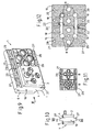
- a multiple coupling 1 according to the invention serves for the simultaneous connection or disconnection of a plurality of media lines or fluid channels in any flow and / or pressure medium systems.
- the multiple clutch 1 two plate-like coupling parts 2 and 4 on.
- Fig. 1 to 4 and Fig. 9 to 16 still a third plate-shaped coupling part 6 is provided.
- These coupling parts each have a plurality of line channels 8 with a corresponding number of Ftuid connector parts, on the one hand male parts 10 and on the other hand sleeve openings 12, such that these fluid connector parts 10, 12 by merging the respective coupling parts 2 and 4 or 4 and 6 in pairs in a direction perpendicular to the plate planes joining direction 14 can be plugged together or vice versa from each other are solvable.
- the coupling part 4 is one of the coupling parts, as shown, the coupling part 4, additionally formed as a cross connector 16 with at least one transverse to the joining direction 14 transverse channel 18 and at least one assigned thereto, arranged in the outer edge region of the coupling part 4 additional connector part, wherein the additional connector part in turn, preferably as a connector part, namely as a plug 20 or sleeve 22, is formed.
- the transverse channel 18 may be in fluid communication with at least one of the ducts 8. This is on Fig. 3 . Fig. 5 , upper area as well as on Fig. 7, 8 . 12 and 16 directed.
- the or a further transverse channel 18 can also run independently of the line channels 8 through the coupling part 4 forming the transverse connector 16 (see in each case the middle, lower region in FIG Fig. 5 and 16 ).
- Each cross channel 18 is associated with at least one additional connector part 20 or 22 ( Fig. 12 . 16 ). It is also possible that the transverse channel 18 connects at least two additional connector parts 20 and 22, which are then arranged in particular in opposite outer edge regions of the coupling part 4 or of the transverse connector 16 ( Fig. 1 to 5 and 16 ).
- the cross-connector 16 forming coupling part 4 an even number of additional connector parts 20 and 22, which are arranged and formed in each case as half plug 20 and half as sleeves 22 that the cross connector 16 with at least one other similar or similar cross-connector 16 in a direction perpendicular to the joining direction 14 transverse joining 24 can be coupled.
- additional connector parts 20 and 22 which are arranged and formed in each case as half plug 20 and half as sleeves 22 that the cross connector 16 with at least one other similar or similar cross-connector 16 in a direction perpendicular to the joining direction 14 transverse joining 24 can be coupled.
- two coupling parts 4 of two couplings B are coupled directly to each other in transverse direction 24.
- Fig. 8 can also two cross-connector 16 indirectly via a special additional transverse connector 26 or according to Fig. 5 . 13 to 16 be coupled via a cross connector 16.
- Fig. 15 Thus, two clutches B can be cross-linked via a coupling A.
- the auxiliary transverse connector 26 need not be part of a multiple clutch.
- the or each formed as a cross-connector 16 coupling part 4 as fluid connector parts exclusively socket openings 12 for inserting plug parts 10 of the other coupling part 2, 6 on.
- the / each cross connector 16 may have at least one mounting portion 27 protruding marginally with fastening holes 29.
- the plug parts 10 of the coupling parts 2 and 6 are formed as separate insert parts 28, according to 3 and 4 are held fixed in receiving openings of the respective coupling part 2, 6 in particular via latching means 30. Details of this preferred embodiment are also in the publications EP 0 618 393 A1 and WO 2006/077264 A1 described.
- At least the / each cross-connector 16 is preferably formed as a one-piece molded part, in particular made of plastic (see in particular Fig. 9 and 13 ).
- the additional connector parts for the cross connections do not necessarily have to be designed as plug connectors.
- it may be at least partially also screw (inner and / or male threaded sections), in particular for connecting lines.
- the preferred connectors of the cross connector 16 may all be formed as sockets 22 (or plug 20), which can then be connected in pairs via separate double connector (double sockets).
Landscapes
- Engineering & Computer Science (AREA)
- General Engineering & Computer Science (AREA)
- Mechanical Engineering (AREA)
- Quick-Acting Or Multi-Walled Pipe Joints (AREA)
Description
- Die vorliegende Erfindung betrifft eine Mehrfachkupplung gemäß dem Oberbegriff des Anspruchs 1.
- Solche Mehrfachkupplungen (siehe dazu beispielsweise die Veröffentlichungen
DE 74 21 926 U ,DE 20 2005 020 263 U1 ,WO 2006/077264 A1 undEP 0 618 393 A1 ) haben den Vorteil, dass mehrere Medienleitungen (Fluidkanäle) gleichzeitig bzw. gemeinsam verbunden oder getrennt werden können. Dazu sind die plattenförmigen Kupplungsteile mit Steckverbinderteilen und zwar Stecker- und Muffenteilen, ausgestattet, so dass durch Zusammenführen der Kupplungsteile in einer zu den Plattenebenen senkrechten Fügerichtung die Steckverbinderteile zusammensteckbar bzw. in umgekehrter Richtung lösbar sind. - Die Veröffentlichung
DE 40 33 050 A1 beschreibt ebenfalls eine solche Mehrfachkupplung der dem Oberbegriff des Anspruchs 1 entsprechenden Art. Diese bekannte Mehrfachkupplung weist allerdings eine insofern besondere Ausgestaltung auf, als diese zusätzliche Sperrventile in den Leitungskanälen aufweist; es handelt sich um eine "auslaufsichere Sperrventileinrichtung". Im Übrigen haben die Leitungskanäle einen abgewinkelten Verlauf. Sie bestehen jeweils aus einem in Fügerichtung der Steckverbinderteile verlaufenden Abschnitt, der über einen quer verlaufenden Abschnitt in einen Leitungsverbinder übergeht. - Der Erfindung liegt die Aufgabe zu Grunde, eine Mehrfachkupplung der genannten Art hinsichtlich ihrer Einsatzmöglichkeiten zu verbessern bzw. zu erweitern.
- Erfindungsgemäß wird dies durch die Merkmale des Patentanspruchs erreicht. Vorteilkafte Ausgestaltungen sind in den abhängigen Ansprüchen enthalten.
- Demnach ist eines von drei Kupplungsteilen zusätzlich als Querverbinder mit mindestens einem quer zur Fügerichtung verlaufenden Querkanal und mindestens einem im Außenrandbereich des Kupplungsteils angeordneten Zusatz-Verbinderteil ausgebildet. Durch diese vorteilhafte Ausgestaltung erhält die erfindungsgemäße Mehrfachkupplung eine zusätzliche Verteilungsfunktion, indem das als Querverbinder ausgestaltete Kupplungsteil mit mindestens einer zusätzlichen Quer-Abzweigung ausgebildet ist. Dabei kann der mindestens eine Querkanal mit mindestens einem der vorhandenen Leitungskanäle verbunden sein. Zusätzlich oder alternativ kann ein Querkanal auch unabhängig von den übrigen Leitungskanälen durch den Querverbinder verlaufen. Hierbei verbindet der Querkanal dann mindestens zwei Zusatz-Verbinderteile miteinander, die insbesondere in gegenüberliegenden Außenrandbereichen des Kupplungsteils angeordnet sind. Das/jedes Zusatz-Verbinderteil ist bevorzugt als Steckverbinderteil (Stecker oder Muffe) ausgebildet, wodurch Querverbindungen besonders einfach durch Zusammenstecken hergestellt oder durch Auseinanderziehen getrennt werden können.
- Durch die erfindungsgemäße Ausgestaltung kann eine Art Baukastensystem realisiert werden, wobei mehrere (d. h. mindestens zwei) Mehrfachkupplungen unmittelbar oder mittelbar über die Querverbinder verbunden werden können. Hierdurch erübrigen sich vorteilhafterweise für solche Verbindungen zusätzliche Leitungen und Verzweigungsstücke.
- Weitere vorteilhafte Ausgestaltungsmerkmale der Erfindung sind in den abhängigen Ansprüche und der folgenden Beschreibung enthalten.
- Anhand der Zeichnungen soll die Erfindung beispielhaft genauer erläutert werden. Dabei zeigen:
- Fig. 1
- eine Perspektivansicht einer bevorzugten Ausführungsform einer erfindungsgemäßen Mehrfachkupplung im gekuppelten Zustand,
- Fig. 2
- eine Draufsicht der Mehrfachkupplung in Pfeilrichtung II gemäß
Fig. 1 , - Fig. 3
- einen Querschnitt in der Ebene III-III in
Fig. 2 , - Fig. 4
- einen stark vergrößerten Schnitt längs der Schnittlinie IV-IV in
Fig. 2 , - Fig. 5
- in einer Draufsicht ähnlich
Fig. 2 eine beispielhafte Anordnung mit mehreren erfindungsgemäßen Mehrfachkupplungen, - Fig. 6
- eine weitere, stark schematische Draufsicht einer Anordnung mit zwei erfindungsgemäßen Querverbindem,
- Fig. 7
- einen Schnitt in der Ebene VII-VII gemäß
Fig. 6 , - Fig. 8
- eine Darstellung analog zu
Fig. 7 , jedoch mit einem zusätzlichen Querverbinderteil, - Fig. 9
- eine Perspektivansicht mit zwei querverbundenen Mehrfachkupplungen,
- Fig. 10
- eine Seitenansicht (verkleinert) in Pfeilrichtung X gemäß
Fig. 9 , - Fig. 11
- eine verkleinerte Prinzipansicht zu
Fig. 9 , - Fig. 12
- einen vergrößerten Querschnitt in der Ebene XII-XII in
Fig. 10 , - Fig.13
- eine Perspektivansicht von zwei mittelbar über eine dritte Kopplung querverbundenen Mehrfachkupplungen,
- Fig.14
- eine Seitenansicht (Pfeilrichtung XIV in
Fig. 13 ), - Fig.15
- eine schematische Vorderansicht zu
Fig. 13 und - Fig.16
- einen vergrößerten Querschnitt in der Ebene XVI-XVI in
Fig.14 . - In den verschiedenen Figuren der Zeichnung sind gleiche Teile stets mit den gleichen Bezugszeichen versehen.
- Eine erfindungsgemäße Mehrfachkupplung 1 dient zum gleichzeitigen Verbinden oder Trennen von mehreren Medienleitungen bzw. Fluidkanälen in beliebigen Strömungs- und/oder Druckmittelsystemen. Dazu weist die Mehrfachkupplung 1 zwei plattenartige Kupplungsteile 2 und 4 auf. Weiterhin ist gemäß
Fig. 1 bis 4 undFig. 9 bis 16 noch ein drittes plattenförmiges Kupplungsteil 6 vorgesehen. Diese Kupplungsteile weisen jeweils mehrere Leitungskanäle 8 mit einer entsprechenden Anzahl von Ftuid-Steckverbinderteilen, und zwar einerseits Steckerteilen 10 und andererseits Muffenöffnungen 12, derart auf, dass diese Fluid-Steckverbinderteile 10, 12 durch Zusammenführen der jeweiligen Kupplungsteile 2 und 4 bzw. 4 und 6 paarweise in einer zu den Plattenebenen senkrechten Fügerichtung 14 zusammensteckbar bzw. umgekehrt voneinander lösbar sind. - Erfindungsgemäß ist eines der Kupplungsteile, und zwar wie dargestellt das Kupplungsteil 4, zusätzlich als Querverbinder 16 mit mindestens einem quer zur Fügerichtung 14 verlaufenden Querkanal 18 und mindestens einem diesem zugeordneten, im Außenrandbereich des Kupplungsteils 4 angeordneten Zusatz-Verbinderteil ausgebildet, wobei das Zusatz-Verbinderteil seinerseits vorzugsweise als Steckverbinderteil, und zwar als Stecker 20 oder Muffe 22, ausgebildet ist.
- Der Querkanal 18 kann mit mindestens einem der Leitungskanäle 8 in Fluidverbindung stehen. Hierzu wird auf
Fig. 3 ,Fig. 5 , oberer Bereich sowie auch aufFig. 7, 8 ,12 und16 verwiesen. Der oder ein weiterer Querkanal 18 kann auch unabhängig von den Leitungskanälen 8 durch das den Querverbinder 16 bildende Kupplungsteil 4 verlaufen (s. jeweils den mittleren, unteren Bereich inFig. 5 und16 ). Dabei ist jedem Querkanal 18 mindestens ein Zusatz-Steckverbinderteil 20 oder 22 zugeordnet (Fig. 12 ,16 ). Es ist auch möglich, dass der Querkanal 18 mindestens zwei Zusatz-Steckverbinderteile 20 bzw. 22 miteinander verbindet, die dann insbesondere in gegenüberliegenden Außenrandbereichen des Kupplungsteils 4 bzw. des Querverbinders 16 angeordnet sind (Fig. 1 bis 5 und16 ). - In weiterer bevorzugter Ausgestaltung weist das den Querverbinder 16 bildende Kupplungsteil 4 eine geradzahlige Anzahl von Zusatz-Steckverbinderteilen 20 und 22 auf, die derart angeordnet sowie jeweils zur Hälfte als Stecker 20 und zur Hälfte als Muffen 22 ausgebildet sind, dass der Querverbinder 16 mit mindestens einem weiteren ähnlichen oder gleichartigen Querverbinder 16 in einer zu der Fügerichtung 14 senkrechten Querfügerichtung 24 kuppelbar ist. Damit kann eine Art Baukastensystem realisiert werden, wobei die Bestandteile teilweise als "Gleichteile" ausgebildet sein können.
- Beispielsweise können gemäß
Fig. 6, 7 sowie 9 bis 12 zwei als Querverbinder 16 ausgebildete Kupplungsteile 4 zweier Kupplungen B (Fig. 11 ) unmittelbar miteinander in Querfügerichtung 24 gekuppelt werden. GemäßFig. 8 können auch zwei Querverbinder 16 mittelbar über einen speziellen Zusatzquerverbinder 26 oder gemäßFig. 5 ,13 bis 16 über einen Querverbinder 16 kuppelbar sein. GemäßFig. 15 können so zwei Kupplungen B über eine Kupplung A querverbunden werden. Der Zusatzquerverbinder 26 muss nicht Teil einer Mehrfachkupplung sein. - In weiterer bevorzugter Ausgestaltung weist das bzw. jedes als Querverbinder 16 ausgebildete Kupplungsteil 4 alsFluid-Steckverbinderteile ausschließlich Muffenöffnungen 12 zum Einstecken von Steckerteilen 10 des jeweils anderen Kupplungsteils 2, 6 auf. Ferner kann der/jeder Querverbinder 16 mindestens einen randlich vorstehenden Montageabschnitt 27 mit Befestigungslöchem 29 aufweisen. Weiterhin ist es vorteilhaft, wenn die Steckerteile 10 der Kupplungsteile 2 und 6 als gesonderte Einsatzteile 28 ausgebildet sind, die gemäß
Fig. 3 und 4 in Aufnahmeöffnungen des jeweiligen Kupplungsteils 2, 6 insbesondere über Rastmittel 30 fixiert gehalten sind. Einzelheiten zu dieser bevorzugten Ausgestaltung sind auch in den VeröffentlichungenEP 0 618 393 A1 undWO 2006/077264 A1 beschrieben. - Zumindest der/jeder Querverbinder 16 ist bevorzugt als einstückiges Formteil insbesondere aus Kunststoff gebildet (s. insbesondere
Fig. 9 und13 ). - Die Erfindung ist nicht auf die dargestellten und beschriebenen Ausführungsbeispiele beschränkt, sondern umfasst auch alle im Sinne der Erfindung gleichwirkenden Ausführungen. So müssen die Zusatz-Verbinderteile für die Querverbindungen nicht unbedingt als Steckverbinder ausgebildet sein. Beispielsweise kann es sich zumindest teilweise auch um Verschraubungen (Innen- und/oder Außengewindeabschnitte) handeln, insbesondere zum Anschluss von Leitungen. Die bevorzugten Steckverbinder der Querverbinder 16 können allesamt als Muffen 22 (oder Stecker 20) ausgebildet sein, die dann paarweise über gesonderte Doppelstecker (Doppelmuffen) verbunden werden können.
Claims (8)
- Mehrfachkupplung (1) zum gleichzeitigen Verbinden oder Trennen von mehreren Medienleitungen, mit zwei plattenartigen Kupplungsteilen (2, 4), die jeweils mehrere Leitungskanäle (8) mit einer entsprechenden Anzahl von Fluid-Steckverbinderteilen (10,12) derart aufweisen, dass die Steckverbinderteile (10,12) durch Zusammenführen der Kupplungsteile (2, 4) paarweise in einer Fügerichtung (14) zusammensteckbar sind,
dadurch gekennzeichnet, dass das eine, erste Kupplungsteil (4) auf seiner dem anderen, zweiten Kupplungsteil (2) gegenüberliegenden Seite in entsprechender Weise über Steckverbinderteile (10,12) mit einem weiteren, dritten Kupplungsteil (6) kuppelbar ist, wobei das erste Kupplungsteil (4) zusätzlich als Querverbinder (16) mit mindestens einem zusätzlich zu den Leitungskanälen (8) quer zur Fügerichtung (14) verlaufenden Querkanal (18) und mindestens einem im Außenrandbereich des Kupplungsteils (4) angeordneten Zusatz-Verbinderteil (20, 22) ausgebildet ist. - Mehrfachkupplung nach Anspruch 1,
dadurch gekennzeichnet, dass derQuerkanal(18)mit mindestens einem der Leitungskanäle (8) verbunden ist. - Mehrfachkupplung nach Anspruch 1 oder 2,
dadurch gekennzeichnet, dass der Querkanal (18) unabhängig von den Leitungskanälen (8) durch das den Querverbinder (16) bildende Kupplungsteil (4) verläuft. - Mehrfachkupplung nach einem der Ansprüche 1 bis 3,
dadurch gekennzeichnet, dass der Querkanal (18) mindestens zwei Zusatz-Verbinderteile (20, 22) miteinander verbindet, die insbesondere in gegenüberliegenden Außenrandbereichen des Kupplungsteils (4) angeordnet sind. - Mehrfachkupplung nach einem der Ansprüche 1 bis 4,
dadurch gekennzeichnet, dass dasdenQuerverbinder(16) bildende Kupplungsteil (4) eine geradzahlige Anzahl von Zusatz-Verbinderteilen (20, 22) aufweist, die derart angeordnet sowie jeweils zur Hälfte als Stecker (20) und zur Hälfte als Muffen (22) ausgebildet sind, dass der Querverbinder (16) mit mindestens einem weiteren ähnlichen oder gleichartigen Querverbinder (16) in einer zu der Fügerichtung (14) senkrechten Querfügerichtung (24) durch Zusammenstecken kuppelbar ist. - Mehrfachkupplung nach einem der Ansprüche 1 bis 5,
dadurch gekennzeichnet, dass zwei als Querverbinder (16) insbesondere gleich ausgebildete Kupplungsteile (4) unmittelbar miteinander oder mittelbar über einen weiteren Querverbinder (16) und/oder einen speziellen Zusatzquerverbinder (26) in Querfügerichtung (24) kuppelbar sind. - Mehrfachkupplung nach einem der Ansprüche 1 bis 6,
dadurch gekennzeichnet, dass dasdenQuerverbinder(16) bildende Kupplungsteil (4) als Fluid-Steckverbinderteile Muffenöffnungen (12) zum Einstecken von Steckerteilen (10) der beiden anderen Kupplungsteile (2, 6) aufweist. - Mehrfachkupplung nach Anspruch 7,
dadurch gekennzeichnet, dass die Steckerteile (10) des zweiten Kupplungsteils (2) und des dritten Kupplungsteils (6) als gesonderte Einsatzteile (28) ausgebildet sind, die in Aufnahmeöffnungen des jeweiligen Kupplungsteils (2, 6) insbesondere über Rastmittel (30) fixiert gehalten sind.
Applications Claiming Priority (2)
| Application Number | Priority Date | Filing Date | Title |
|---|---|---|---|
| DE202008002206U DE202008002206U1 (de) | 2008-02-15 | 2008-02-15 | Mehrfach-Steckkupplung für Medienleitungen |
| PCT/EP2009/051498 WO2009101076A1 (de) | 2008-02-15 | 2009-02-10 | Mehrfach-steckkupplung für medienleitungen |
Publications (2)
| Publication Number | Publication Date |
|---|---|
| EP2240718A1 EP2240718A1 (de) | 2010-10-20 |
| EP2240718B1 true EP2240718B1 (de) | 2012-10-03 |
Family
ID=40651834
Family Applications (1)
| Application Number | Title | Priority Date | Filing Date |
|---|---|---|---|
| EP09710625A Not-in-force EP2240718B1 (de) | 2008-02-15 | 2009-02-10 | Mehrfach-steckkupplung für medienleitungen |
Country Status (4)
| Country | Link |
|---|---|
| US (1) | US20110012341A1 (de) |
| EP (1) | EP2240718B1 (de) |
| DE (1) | DE202008002206U1 (de) |
| WO (1) | WO2009101076A1 (de) |
Families Citing this family (10)
| Publication number | Priority date | Publication date | Assignee | Title |
|---|---|---|---|---|
| DE102012004165A1 (de) | 2012-03-05 | 2013-09-05 | Voss Automotive Gmbh | Kontollsystem und Verfahren zur Kontrolle der Montage einer Kupplungseinrichtung |
| GB201213434D0 (en) | 2012-07-27 | 2012-09-12 | Novacta Biosystems Ltd | The use of type-B lantibiotic-based compounds having antimicrobial activity |
| GB201322738D0 (en) * | 2013-12-20 | 2014-02-05 | Agco Int Gmbh | Hydraulic coupling seal |
| USD869615S1 (en) * | 2018-02-09 | 2019-12-10 | Cnh Industrial America Llc | Hydraulic multi-coupler having an interference tab |
| USD868948S1 (en) * | 2018-02-09 | 2019-12-03 | Cnh Industrial America Llc | Hydraulic multi-coupler having an optional port |
| KR102773819B1 (ko) * | 2020-08-03 | 2025-03-04 | 한온시스템 주식회사 | 플랜지, 배관 및 플랜지 구조 |
| DE102022122296A1 (de) * | 2022-09-02 | 2024-03-07 | Voss Automotive Gmbh | Mehrfachkupplung für Medienleitungen und Kupplungsträger |
| JP2026505294A (ja) * | 2023-02-16 | 2026-02-13 | アイコール・システムズ・インク | モジュラー基板組立体およびそれを組み込んだシステム |
| EP4685376A1 (de) * | 2024-07-24 | 2026-01-28 | Johannes Schäfer vorm. Stettiner Schraubenwerke GmbH & Co. KG | Steckverbindungssystem |
| WO2026046834A1 (de) * | 2024-09-02 | 2026-03-05 | Voss Automotive Gmbh | Kupplungseinrichtung für wanddurchführungen von medienleitungen, grundplatte und kupplungsmodul sowie verwendung der grundplatte und verwendung des kupplungsmoduls |
Family Cites Families (25)
| Publication number | Priority date | Publication date | Assignee | Title |
|---|---|---|---|---|
| DE7421926U (de) | 1974-11-07 | Armaturenfabrik Voss H | Schlauch-Sammelkupplung | |
| US2834368A (en) * | 1955-08-01 | 1958-05-13 | Landon R Gray | Multiple valve assembly |
| US3326579A (en) * | 1964-05-27 | 1967-06-20 | Rockwell Mfg Co | Multiple conduit connection |
| US5082245A (en) | 1990-02-21 | 1992-01-21 | General Electric Company | Spill proof check valve apparatus |
| DE4310370A1 (de) | 1993-03-30 | 1994-10-06 | Voss Armaturen | Kupplungseinrichtung für Schlauch- und/oder Rohrleitungen |
| US5988203A (en) * | 1997-10-01 | 1999-11-23 | Hutton; Peter B. | Two-piece manifold |
| US5881773A (en) * | 1997-12-12 | 1999-03-16 | Lube Devices, Inc. | Complementary joints to mechanically and removably join fluid valve bodies together in fluid communication with one another |
| TW481224U (en) * | 2001-08-24 | 2002-03-21 | Shako Co Ltd | Structure improvement for pneumatic adjustment component |
| US20030079786A1 (en) * | 2001-10-30 | 2003-05-01 | Diana Michael J. | Modular fluid pressure regulator with bypass |
| DE10163785A1 (de) * | 2001-12-22 | 2003-07-03 | Mueller A & K Gmbh Co Kg | Einrichtung zum Zusammenschalten mehrerer hydraulischer oder pneumatischer Komponenten, insbesondere mehrerer Elektromagnetventile |
| JP3947968B2 (ja) * | 2002-04-19 | 2007-07-25 | Smc株式会社 | マニホールドの接続機構 |
| US6682001B2 (en) * | 2002-06-19 | 2004-01-27 | Illinois Tool Works Inc. | Modular color changer |
| US6929032B2 (en) * | 2003-04-02 | 2005-08-16 | Sea Tech, Inc. | Manifold |
| JP4431940B2 (ja) * | 2003-04-10 | 2010-03-17 | 旭有機材工業株式会社 | 配管部材の接続構造 |
| US7178556B2 (en) * | 2003-08-07 | 2007-02-20 | Parker-Hannifin Corporation | Modular component connector substrate assembly system |
| KR100536294B1 (ko) * | 2003-11-14 | 2005-12-14 | 주식회사 만도 | 안티록 브레이크시스템용 유압유닛 및 그 제조방법 |
| US7370674B2 (en) * | 2004-02-20 | 2008-05-13 | Michael Doyle | Modular fluid distribution system |
| DE102004010148A1 (de) * | 2004-02-27 | 2005-09-15 | Deere & Company, Moline | Gehäusestruktur |
| US7434595B2 (en) * | 2004-08-30 | 2008-10-14 | Watts Water Technologies, Inc. | Safety valve assembly having set and reset mechanisms |
| DE202005001153U1 (de) | 2005-01-24 | 2006-06-08 | Voss Automotive Gmbh | Kupplungseinrichtung für Medienleitungen |
| DE202005019650U1 (de) * | 2005-12-16 | 2007-04-19 | Voss Automotive Gmbh | Mehrfach-Kupplung für Medienleitungen |
| DE202005020263U1 (de) | 2005-12-23 | 2007-04-26 | Voss Automotive Gmbh | Mehrfachkupplung für Medienleitungen |
| US7914084B2 (en) * | 2006-02-02 | 2011-03-29 | White Drive Products, Inc. | Control component for hydraulic circuit including spring applied-hydraulically released brake |
| US20070289652A1 (en) * | 2006-06-16 | 2007-12-20 | Matheson Tri-Gas | High flow surface mount components |
| US7806143B2 (en) * | 2007-06-11 | 2010-10-05 | Lam Research Corporation | Flexible manifold for integrated gas system gas panels |
-
2008
- 2008-02-15 DE DE202008002206U patent/DE202008002206U1/de not_active Expired - Lifetime
-
2009
- 2009-02-10 EP EP09710625A patent/EP2240718B1/de not_active Not-in-force
- 2009-02-10 US US12/867,066 patent/US20110012341A1/en not_active Abandoned
- 2009-02-10 WO PCT/EP2009/051498 patent/WO2009101076A1/de not_active Ceased
Also Published As
| Publication number | Publication date |
|---|---|
| WO2009101076A1 (de) | 2009-08-20 |
| US20110012341A1 (en) | 2011-01-20 |
| EP2240718A1 (de) | 2010-10-20 |
| DE202008002206U1 (de) | 2009-06-25 |
Similar Documents
| Publication | Publication Date | Title |
|---|---|---|
| EP2240718B1 (de) | Mehrfach-steckkupplung für medienleitungen | |
| WO2023046530A1 (de) | Kühlkörper | |
| DE4443081A1 (de) | Einrichtung zum Zusammenschalten mehrerer Elektromagnetventile | |
| DE102008055994B4 (de) | Baukastensystem zum Aufbau von Verteilerrohren für Getränkeautomaten und Verteilerrohr für Getränkeautomaten | |
| EP3921551B1 (de) | Winkelstück zum fluidkommunizierenden verbinden von fluidleitungen eines fahrzeugs | |
| EP1538708B1 (de) | Ladesteckverbindersatz mit Adapter | |
| EP2449302B1 (de) | Kupplungsanordnung | |
| WO2019174854A1 (de) | Brückenelement zur herstellung einer elektrischen verbindung sowie anordnung | |
| EP1513225B1 (de) | Verriegelungselement für eine Steckverbindung | |
| DE3014695A1 (de) | Verdrahtungskanal | |
| DE102011050805A1 (de) | Filtriervorrichtung für hochviskose Fluide | |
| EP2733403A1 (de) | Kupplungseinrichtung für Medienleitungen | |
| DE102020211603A1 (de) | Vorrichtung zum temperieren eines bauteils und herstellungsverfahren der vorrichtung | |
| EP2501870A1 (de) | Versickerungsmodul sowie damit gebildetes versickerungssystem | |
| DE10322878A1 (de) | Anordnung zum dichtenden Verbinden zweier rohrförmiger Elemente | |
| WO2005036025A1 (de) | Kettenlasche, kettenglied und energieführungskette, sowie zwischenstück für eine energieführungskette, mit torsionsgekoppelten verriegelungsmitteln zum verbinden von quersteg und kettenlasche | |
| DE102022122296A1 (de) | Mehrfachkupplung für Medienleitungen und Kupplungsträger | |
| DE20209957U1 (de) | Rückensteife Kette | |
| DE102006060238A1 (de) | Steckverbindung, bestehend aus einem Stecker sowie einem Kuppler mit einem Kontaktträger und einem Schutzkragen | |
| DE102014009831A1 (de) | Mehrteiliger, konzentrischer Verteiler und Verfahren zur Herstellung des Verteilers | |
| EP2863492B1 (de) | Steckverbinder mit einem Primärverriegelung und einer Steckerpositionssicherung (CPA) mit Flügeln | |
| DE202018107456U1 (de) | Verteiler für Medienleitungen | |
| DE10029971B4 (de) | Einrichtung zum Absichern einer lösbaren Verbindung gegen ein unbefugtes Lösen | |
| EP1233227A1 (de) | Steckverbindung für Strömungsmittelleitungen | |
| WO2018177918A1 (de) | Verfahren zur verbindung von drei bauteilen und verbindbares system zur durchführung des verfahrens |
Legal Events
| Date | Code | Title | Description |
|---|---|---|---|
| PUAI | Public reference made under article 153(3) epc to a published international application that has entered the european phase |
Free format text: ORIGINAL CODE: 0009012 |
|
| 17P | Request for examination filed |
Effective date: 20100719 |
|
| AK | Designated contracting states |
Kind code of ref document: A1 Designated state(s): AT BE BG CH CY CZ DE DK EE ES FI FR GB GR HR HU IE IS IT LI LT LU LV MC MK MT NL NO PL PT RO SE SI SK TR |
|
| AX | Request for extension of the european patent |
Extension state: AL BA RS |
|
| RIN1 | Information on inventor provided before grant (corrected) |
Inventor name: HASBERG, MARKUS Inventor name: HAGEN, HARALD Inventor name: SUHR, ANDREAS |
|
| RIN1 | Information on inventor provided before grant (corrected) |
Inventor name: SUHR, ANDREAS Inventor name: HAGEN, HARALD Inventor name: HASBERG, MARKUS |
|
| 17Q | First examination report despatched |
Effective date: 20110303 |
|
| DAX | Request for extension of the european patent (deleted) | ||
| GRAP | Despatch of communication of intention to grant a patent |
Free format text: ORIGINAL CODE: EPIDOSNIGR1 |
|
| GRAS | Grant fee paid |
Free format text: ORIGINAL CODE: EPIDOSNIGR3 |
|
| GRAA | (expected) grant |
Free format text: ORIGINAL CODE: 0009210 |
|
| AK | Designated contracting states |
Kind code of ref document: B1 Designated state(s): AT BE BG CH CY CZ DE DK EE ES FI FR GB GR HR HU IE IS IT LI LT LU LV MC MK MT NL NO PL PT RO SE SI SK TR |
|
| REG | Reference to a national code |
Ref country code: GB Ref legal event code: FG4D Free format text: NOT ENGLISH |
|
| REG | Reference to a national code |
Ref country code: AT Ref legal event code: REF Ref document number: 578141 Country of ref document: AT Kind code of ref document: T Effective date: 20121015 Ref country code: CH Ref legal event code: EP |
|
| REG | Reference to a national code |
Ref country code: IE Ref legal event code: FG4D Free format text: LANGUAGE OF EP DOCUMENT: GERMAN |
|
| REG | Reference to a national code |
Ref country code: DE Ref legal event code: R096 Ref document number: 502009004955 Country of ref document: DE Effective date: 20121129 |
|
| REG | Reference to a national code |
Ref country code: NL Ref legal event code: T3 |
|
| REG | Reference to a national code |
Ref country code: SE Ref legal event code: TRGR |
|
| PG25 | Lapsed in a contracting state [announced via postgrant information from national office to epo] |
Ref country code: SI Free format text: LAPSE BECAUSE OF FAILURE TO SUBMIT A TRANSLATION OF THE DESCRIPTION OR TO PAY THE FEE WITHIN THE PRESCRIBED TIME-LIMIT Effective date: 20121003 |
|
| REG | Reference to a national code |
Ref country code: LT Ref legal event code: MG4D |
|
| PG25 | Lapsed in a contracting state [announced via postgrant information from national office to epo] |
Ref country code: HR Free format text: LAPSE BECAUSE OF FAILURE TO SUBMIT A TRANSLATION OF THE DESCRIPTION OR TO PAY THE FEE WITHIN THE PRESCRIBED TIME-LIMIT Effective date: 20121003 Ref country code: ES Free format text: LAPSE BECAUSE OF FAILURE TO SUBMIT A TRANSLATION OF THE DESCRIPTION OR TO PAY THE FEE WITHIN THE PRESCRIBED TIME-LIMIT Effective date: 20130114 Ref country code: NO Free format text: LAPSE BECAUSE OF FAILURE TO SUBMIT A TRANSLATION OF THE DESCRIPTION OR TO PAY THE FEE WITHIN THE PRESCRIBED TIME-LIMIT Effective date: 20130103 Ref country code: LT Free format text: LAPSE BECAUSE OF FAILURE TO SUBMIT A TRANSLATION OF THE DESCRIPTION OR TO PAY THE FEE WITHIN THE PRESCRIBED TIME-LIMIT Effective date: 20121003 Ref country code: IS Free format text: LAPSE BECAUSE OF FAILURE TO SUBMIT A TRANSLATION OF THE DESCRIPTION OR TO PAY THE FEE WITHIN THE PRESCRIBED TIME-LIMIT Effective date: 20130203 Ref country code: FI Free format text: LAPSE BECAUSE OF FAILURE TO SUBMIT A TRANSLATION OF THE DESCRIPTION OR TO PAY THE FEE WITHIN THE PRESCRIBED TIME-LIMIT Effective date: 20121003 |
|
| PGFP | Annual fee paid to national office [announced via postgrant information from national office to epo] |
Ref country code: SE Payment date: 20130226 Year of fee payment: 5 Ref country code: FR Payment date: 20130408 Year of fee payment: 5 |
|
| PG25 | Lapsed in a contracting state [announced via postgrant information from national office to epo] |
Ref country code: PT Free format text: LAPSE BECAUSE OF FAILURE TO SUBMIT A TRANSLATION OF THE DESCRIPTION OR TO PAY THE FEE WITHIN THE PRESCRIBED TIME-LIMIT Effective date: 20130204 Ref country code: LV Free format text: LAPSE BECAUSE OF FAILURE TO SUBMIT A TRANSLATION OF THE DESCRIPTION OR TO PAY THE FEE WITHIN THE PRESCRIBED TIME-LIMIT Effective date: 20121003 Ref country code: PL Free format text: LAPSE BECAUSE OF FAILURE TO SUBMIT A TRANSLATION OF THE DESCRIPTION OR TO PAY THE FEE WITHIN THE PRESCRIBED TIME-LIMIT Effective date: 20121003 Ref country code: GR Free format text: LAPSE BECAUSE OF FAILURE TO SUBMIT A TRANSLATION OF THE DESCRIPTION OR TO PAY THE FEE WITHIN THE PRESCRIBED TIME-LIMIT Effective date: 20130104 |
|
| PG25 | Lapsed in a contracting state [announced via postgrant information from national office to epo] |
Ref country code: BG Free format text: LAPSE BECAUSE OF FAILURE TO SUBMIT A TRANSLATION OF THE DESCRIPTION OR TO PAY THE FEE WITHIN THE PRESCRIBED TIME-LIMIT Effective date: 20130103 Ref country code: SK Free format text: LAPSE BECAUSE OF FAILURE TO SUBMIT A TRANSLATION OF THE DESCRIPTION OR TO PAY THE FEE WITHIN THE PRESCRIBED TIME-LIMIT Effective date: 20121003 Ref country code: CZ Free format text: LAPSE BECAUSE OF FAILURE TO SUBMIT A TRANSLATION OF THE DESCRIPTION OR TO PAY THE FEE WITHIN THE PRESCRIBED TIME-LIMIT Effective date: 20121003 Ref country code: EE Free format text: LAPSE BECAUSE OF FAILURE TO SUBMIT A TRANSLATION OF THE DESCRIPTION OR TO PAY THE FEE WITHIN THE PRESCRIBED TIME-LIMIT Effective date: 20121003 Ref country code: DK Free format text: LAPSE BECAUSE OF FAILURE TO SUBMIT A TRANSLATION OF THE DESCRIPTION OR TO PAY THE FEE WITHIN THE PRESCRIBED TIME-LIMIT Effective date: 20121003 |
|
| PLBE | No opposition filed within time limit |
Free format text: ORIGINAL CODE: 0009261 |
|
| STAA | Information on the status of an ep patent application or granted ep patent |
Free format text: STATUS: NO OPPOSITION FILED WITHIN TIME LIMIT |
|
| PG25 | Lapsed in a contracting state [announced via postgrant information from national office to epo] |
Ref country code: RO Free format text: LAPSE BECAUSE OF FAILURE TO SUBMIT A TRANSLATION OF THE DESCRIPTION OR TO PAY THE FEE WITHIN THE PRESCRIBED TIME-LIMIT Effective date: 20121003 |
|
| BERE | Be: lapsed |
Owner name: VOSS AUTOMOTIVE G.M.B.H. Effective date: 20130228 |
|
| 26N | No opposition filed |
Effective date: 20130704 |
|
| PG25 | Lapsed in a contracting state [announced via postgrant information from national office to epo] |
Ref country code: MC Free format text: LAPSE BECAUSE OF NON-PAYMENT OF DUE FEES Effective date: 20130228 |
|
| REG | Reference to a national code |
Ref country code: CH Ref legal event code: PL |
|
| GBPC | Gb: european patent ceased through non-payment of renewal fee |
Effective date: 20130210 |
|
| PG25 | Lapsed in a contracting state [announced via postgrant information from national office to epo] |
Ref country code: CH Free format text: LAPSE BECAUSE OF NON-PAYMENT OF DUE FEES Effective date: 20130228 Ref country code: LI Free format text: LAPSE BECAUSE OF NON-PAYMENT OF DUE FEES Effective date: 20130228 |
|
| REG | Reference to a national code |
Ref country code: DE Ref legal event code: R097 Ref document number: 502009004955 Country of ref document: DE Effective date: 20130704 |
|
| PG25 | Lapsed in a contracting state [announced via postgrant information from national office to epo] |
Ref country code: CY Free format text: LAPSE BECAUSE OF FAILURE TO SUBMIT A TRANSLATION OF THE DESCRIPTION OR TO PAY THE FEE WITHIN THE PRESCRIBED TIME-LIMIT Effective date: 20121003 |
|
| REG | Reference to a national code |
Ref country code: IE Ref legal event code: MM4A |
|
| PG25 | Lapsed in a contracting state [announced via postgrant information from national office to epo] |
Ref country code: GB Free format text: LAPSE BECAUSE OF NON-PAYMENT OF DUE FEES Effective date: 20130210 Ref country code: BE Free format text: LAPSE BECAUSE OF NON-PAYMENT OF DUE FEES Effective date: 20130228 Ref country code: IE Free format text: LAPSE BECAUSE OF NON-PAYMENT OF DUE FEES Effective date: 20130210 |
|
| PG25 | Lapsed in a contracting state [announced via postgrant information from national office to epo] |
Ref country code: MT Free format text: LAPSE BECAUSE OF FAILURE TO SUBMIT A TRANSLATION OF THE DESCRIPTION OR TO PAY THE FEE WITHIN THE PRESCRIBED TIME-LIMIT Effective date: 20121003 |
|
| REG | Reference to a national code |
Ref country code: SE Ref legal event code: EUG |
|
| REG | Reference to a national code |
Ref country code: FR Ref legal event code: ST Effective date: 20141031 |
|
| PG25 | Lapsed in a contracting state [announced via postgrant information from national office to epo] |
Ref country code: SE Free format text: LAPSE BECAUSE OF NON-PAYMENT OF DUE FEES Effective date: 20140211 |
|
| PG25 | Lapsed in a contracting state [announced via postgrant information from national office to epo] |
Ref country code: FR Free format text: LAPSE BECAUSE OF NON-PAYMENT OF DUE FEES Effective date: 20140228 |
|
| REG | Reference to a national code |
Ref country code: AT Ref legal event code: MM01 Ref document number: 578141 Country of ref document: AT Kind code of ref document: T Effective date: 20140210 |
|
| PG25 | Lapsed in a contracting state [announced via postgrant information from national office to epo] |
Ref country code: AT Free format text: LAPSE BECAUSE OF NON-PAYMENT OF DUE FEES Effective date: 20140210 |
|
| PG25 | Lapsed in a contracting state [announced via postgrant information from national office to epo] |
Ref country code: TR Free format text: LAPSE BECAUSE OF FAILURE TO SUBMIT A TRANSLATION OF THE DESCRIPTION OR TO PAY THE FEE WITHIN THE PRESCRIBED TIME-LIMIT Effective date: 20121003 |
|
| PG25 | Lapsed in a contracting state [announced via postgrant information from national office to epo] |
Ref country code: MK Free format text: LAPSE BECAUSE OF FAILURE TO SUBMIT A TRANSLATION OF THE DESCRIPTION OR TO PAY THE FEE WITHIN THE PRESCRIBED TIME-LIMIT Effective date: 20121003 Ref country code: LU Free format text: LAPSE BECAUSE OF NON-PAYMENT OF DUE FEES Effective date: 20130210 Ref country code: HU Free format text: LAPSE BECAUSE OF FAILURE TO SUBMIT A TRANSLATION OF THE DESCRIPTION OR TO PAY THE FEE WITHIN THE PRESCRIBED TIME-LIMIT; INVALID AB INITIO Effective date: 20090210 |
|
| PG25 | Lapsed in a contracting state [announced via postgrant information from national office to epo] |
Ref country code: IT Free format text: LAPSE BECAUSE OF NON-PAYMENT OF DUE FEES Effective date: 20140210 |
|
| PGFP | Annual fee paid to national office [announced via postgrant information from national office to epo] |
Ref country code: DE Payment date: 20170427 Year of fee payment: 9 |
|
| REG | Reference to a national code |
Ref country code: DE Ref legal event code: R119 Ref document number: 502009004955 Country of ref document: DE |
|
| PG25 | Lapsed in a contracting state [announced via postgrant information from national office to epo] |
Ref country code: DE Free format text: LAPSE BECAUSE OF NON-PAYMENT OF DUE FEES Effective date: 20180901 |
|
| PGFP | Annual fee paid to national office [announced via postgrant information from national office to epo] |
Ref country code: NL Payment date: 20200225 Year of fee payment: 12 |
|
| REG | Reference to a national code |
Ref country code: NL Ref legal event code: MM Effective date: 20210301 |
|
| PG25 | Lapsed in a contracting state [announced via postgrant information from national office to epo] |
Ref country code: NL Free format text: LAPSE BECAUSE OF NON-PAYMENT OF DUE FEES Effective date: 20210301 |