EP2240696B1 - Inlet connecting piece for an axial-flow compressor - Google Patents
Inlet connecting piece for an axial-flow compressor Download PDFInfo
- Publication number
- EP2240696B1 EP2240696B1 EP08872325.9A EP08872325A EP2240696B1 EP 2240696 B1 EP2240696 B1 EP 2240696B1 EP 08872325 A EP08872325 A EP 08872325A EP 2240696 B1 EP2240696 B1 EP 2240696B1
- Authority
- EP
- European Patent Office
- Prior art keywords
- inlet
- bearing
- inlet connector
- housing
- connector according
- Prior art date
- Legal status (The legal status is an assumption and is not a legal conclusion. Google has not performed a legal analysis and makes no representation as to the accuracy of the status listed.)
- Not-in-force
Links
Images

Classifications
-
- F—MECHANICAL ENGINEERING; LIGHTING; HEATING; WEAPONS; BLASTING
- F04—POSITIVE - DISPLACEMENT MACHINES FOR LIQUIDS; PUMPS FOR LIQUIDS OR ELASTIC FLUIDS
- F04D—NON-POSITIVE-DISPLACEMENT PUMPS
- F04D29/00—Details, component parts, or accessories
- F04D29/05—Shafts or bearings, or assemblies thereof, specially adapted for elastic fluid pumps
- F04D29/056—Bearings
- F04D29/059—Roller bearings
-
- F—MECHANICAL ENGINEERING; LIGHTING; HEATING; WEAPONS; BLASTING
- F01—MACHINES OR ENGINES IN GENERAL; ENGINE PLANTS IN GENERAL; STEAM ENGINES
- F01D—NON-POSITIVE DISPLACEMENT MACHINES OR ENGINES, e.g. STEAM TURBINES
- F01D25/00—Component parts, details, or accessories, not provided for in, or of interest apart from, other groups
- F01D25/16—Arrangement of bearings; Supporting or mounting bearings in casings
- F01D25/162—Bearing supports
-
- F—MECHANICAL ENGINEERING; LIGHTING; HEATING; WEAPONS; BLASTING
- F01—MACHINES OR ENGINES IN GENERAL; ENGINE PLANTS IN GENERAL; STEAM ENGINES
- F01D—NON-POSITIVE DISPLACEMENT MACHINES OR ENGINES, e.g. STEAM TURBINES
- F01D9/00—Stators
- F01D9/06—Fluid supply conduits to nozzles or the like
- F01D9/065—Fluid supply or removal conduits traversing the working fluid flow, e.g. for lubrication-, cooling-, or sealing fluids
-
- F—MECHANICAL ENGINEERING; LIGHTING; HEATING; WEAPONS; BLASTING
- F04—POSITIVE - DISPLACEMENT MACHINES FOR LIQUIDS; PUMPS FOR LIQUIDS OR ELASTIC FLUIDS
- F04D—NON-POSITIVE-DISPLACEMENT PUMPS
- F04D19/00—Axial-flow pumps
- F04D19/02—Multi-stage pumps
-
- F—MECHANICAL ENGINEERING; LIGHTING; HEATING; WEAPONS; BLASTING
- F04—POSITIVE - DISPLACEMENT MACHINES FOR LIQUIDS; PUMPS FOR LIQUIDS OR ELASTIC FLUIDS
- F04D—NON-POSITIVE-DISPLACEMENT PUMPS
- F04D29/00—Details, component parts, or accessories
- F04D29/06—Lubrication
- F04D29/063—Lubrication specially adapted for elastic fluid pumps
-
- F—MECHANICAL ENGINEERING; LIGHTING; HEATING; WEAPONS; BLASTING
- F04—POSITIVE - DISPLACEMENT MACHINES FOR LIQUIDS; PUMPS FOR LIQUIDS OR ELASTIC FLUIDS
- F04D—NON-POSITIVE-DISPLACEMENT PUMPS
- F04D29/00—Details, component parts, or accessories
- F04D29/40—Casings; Connections of working fluid
- F04D29/52—Casings; Connections of working fluid for axial pumps
- F04D29/522—Casings; Connections of working fluid for axial pumps especially adapted for elastic fluid pumps
-
- F—MECHANICAL ENGINEERING; LIGHTING; HEATING; WEAPONS; BLASTING
- F04—POSITIVE - DISPLACEMENT MACHINES FOR LIQUIDS; PUMPS FOR LIQUIDS OR ELASTIC FLUIDS
- F04D—NON-POSITIVE-DISPLACEMENT PUMPS
- F04D29/00—Details, component parts, or accessories
- F04D29/60—Mounting; Assembling; Disassembling
- F04D29/64—Mounting; Assembling; Disassembling of axial pumps
- F04D29/644—Mounting; Assembling; Disassembling of axial pumps especially adapted for elastic fluid pumps
-
- F—MECHANICAL ENGINEERING; LIGHTING; HEATING; WEAPONS; BLASTING
- F04—POSITIVE - DISPLACEMENT MACHINES FOR LIQUIDS; PUMPS FOR LIQUIDS OR ELASTIC FLUIDS
- F04D—NON-POSITIVE-DISPLACEMENT PUMPS
- F04D29/00—Details, component parts, or accessories
- F04D29/66—Combating cavitation, whirls, noise, vibration or the like; Balancing
- F04D29/661—Combating cavitation, whirls, noise, vibration or the like; Balancing especially adapted for elastic fluid pumps
- F04D29/668—Combating cavitation, whirls, noise, vibration or the like; Balancing especially adapted for elastic fluid pumps damping or preventing mechanical vibrations
Definitions
- the invention relates to an inlet connection for an axial compressor, in particular a turbocompressor, with an inlet housing, in which a bearing housing is arranged with a first fluid axially in the flow direction of a fluid to be compressed bearing for a rotor of the axial compressor, wherein the bearing housing connected to the inlet housing via an inlet strut is, which is connected in an end cross section with the inlet housing.
- Such intake struts are purely radial in conventional axial compressors, ie. parallel to a normal plane to the longitudinal axis of the inlet nozzle, so that the bearing center of the first or front bearing is arranged axially in the flow direction of a fluid to be compressed substantially at the level of the center of area of this end cross-section, in other words the bearing axially centrally in the inlet strut under the transition is arranged in the inlet housing.
- a piercing point of a bearing axis through a plane of symmetry of a symmetrical bearing, a center of mass of the bearing, the geometric center between the axial end faces of the bearing or a pressure point of the bearing are referred to as the bearing center point.
- the inlet struts in particular for reasons of strength and production, are often connected relatively far forward to the inlet cross-section of the inlet connection with the inlet housing in order to be able to support, for example, against corresponding reinforcements of the inlet housing or to avoid greatly varying wall thicknesses during prototyping, this is also the first one or front bearing arranged correspondingly far forward, so that there is a relatively large bearing distance to a second, rear bearing of the rotor of the axial compressor, which is arranged in the flow direction behind the first bearing.
- one or more fluid passages may be formed.
- Such fluid passages can serve, for example, the lubrication of the bearing and for this purpose open into the bearing housing on the one hand in or near the bearing and on the other hand with a Schmierffenver- or disposal, for example via grease nipples, lines, passages in adjacent housing parts or the like, be connected outside of the inlet housing.
- a Schmierstoffver- or disposal for example via grease nipples, lines, passages in adjacent housing parts or the like, be connected outside of the inlet housing.
- a bearing supplied by the radial fluid passage has to be arranged axially at the level of the outlet opening of the fluid passage from the inlet housing, which also disadvantageously increases the bearing center distance of the rotor.
- a larger bearing center distance can adversely affect the rotor dynamics.
- an inlet nozzle according to the preamble of claim 1 is known. Object of the present invention is therefore to provide an improved inlet nozzle available. To solve this problem, an inlet nozzle according to the preamble of claim 1 is further developed by at least one of its characterizing features.
- Claim 15 provides an axial compressor with such an inlet connection under protection, the dependent claims relate to advantageous developments.
- An inlet connection according to the invention is provided for an axial compressor, in particular a turbocompressor, and may preferably be detachably or fixedly connected or integrally formed therewith. It has an inlet housing, the interior of which preferably tapers in the flow direction of a fluid to be compressed.
- a bearing housing is arranged, which receives a front or first bearing for a rotor of the axial compressor.
- This may in particular be a radial bearing, a thrust bearing or a radial-axial bearing.
- This bearing is axially in the flow direction of a fluid to be compressed, a first, ie front bearing, wherein the rotor in further Bearings can be supported, which have a greater axial distance to an inlet cross-section of the inlet nozzle.
- the bearing housing is supported in the inlet housing via one or more inlet struts.
- inlet struts can be distributed equidistantly over the circumference of the bearing housing or have different angular distances from each other. While equidistantly distributed inlet struts the flow in the bearing housing homogeneous and thus little disturbing, inlet struts with different angular distances to each other can be adapted to constructional boundary conditions of the housing, in particular external leads, ribs, different wall thicknesses or the like.
- One or more inlet struts are connected in each case an end cross section of the corresponding inlet strut with the inlet housing.
- one or more, preferably all inlet struts may be integrally connected to the inlet and / or bearing housing, for example by primary molding.
- one or more inlet struts can also be connected to the entry and / or bearing housing after the prototyping, for example welded or screwed.
- a fluid passage is formed in at least one inlet struts. This can be provided in particular for supplying and / or removing lubricant to the bearing for the impeller.
- a fluid passage can likewise serve for supplying and / or removing cooling fluid, in particular cooling air, and / or a blocking fluid, in particular blocking air, in order to cool the axial compressor or to avoid a lubricant outlet into the axial compressor.
- Other fluids such as a hydraulic fluid, in particular a controlled bearing, can flow through the fluid passage.
- a fluid passage in a preferred embodiment in or in the vicinity of the bearing can open into the bearing housing.
- the fluid passage described so far only for the sake of simplification may, for example, also be designed to guide cables, lines or the like, for example electrical and / or optical lines for sensors in the bearing housing.
- a fluid passage at least partially encloses an acute angle with a normal plane to the longitudinal axis of the inlet nozzle, ie obliquely to the axial direction of the inlet nozzle, in particular from radially outside to radially inside in the direction of flow of the fluid to be compressed.
- the bearing center of the first bearing is in the flow direction of a fluid to be compressed axially at least 0.1 times, preferably at least 0.15 times, more preferably at least 0.2 times and in particular at least 0.25 -fold the chord length of the end cross-section disposed behind the center of area of the end cross-section.
- chord length is the maximum extent of the end cross-section in the axial direction, ie in the flow direction of a fluid to be compressed, which corresponds, for example, to its diameter in the case of a circular end cross-section, and to its large radius in the case of an elliptical cross-section.
- the first bearing is arranged behind the center of area of an end cross-section , This advantageously the bearing distance to the center of mass of the rotor and - if present - shortened to a second, rear bearing of the rotor of the axial compressor, which is arranged downstream of the first bearing in the flow direction.
- the first bearing in particular behind the first two thirds of the chord length, ie at least 0.17-fold, preferably after the first three quarters of the chord length, ie be arranged at least 0.25-fold behind the center of area of the end cross-section.
- the bearing center of the first bearing is axially behind at least 0.1 times, 0.15 times, 0.2 times or 0.25 times the chord length of the end cross section arranged the surface center of the end cross-section of at least one inlet strut.
- inlet struts it is also possible for inlet struts to be present, with respect to whose end cross-section the first bearing is arranged axially in front of or in the center of the surface.
- the bearing center of the first bearing is arranged axially at least 0.1 times, 0.15 times, 0.2 times or 0.25 times the chord length of the end cross section behind the surface centers of the end cross sections of all inlet struts ,
- the bearing center no longer has to lie within the chord length of the end section (s) projected onto the longitudinal axis of the entry socket, but can also be arranged axially behind the end section (s). Equally, however, it can also be located within the chord length of the end cross section projected onto the longitudinal axis of the entry stub, in particular at most 0.75 times, in particular at most 0.5 times the chord length of the end cross section behind the center of the face cross section be.
- first bearing is offset axially to the rear relative to the end cross-section of an inlet strut, it can be operated particularly well by obliquely extending fluid passages in this inlet strut.
- fluid passages can be formed in one or more inlet struts, wherein at least one, preferably several, particularly preferably all fluid passages form an acute angle with a normal plane to the longitudinal axis of the inlet nozzle.
- Such fluid passages may preferably run substantially parallel to one another, which is the production simplified. Likewise, however, they may also include different angles with the normal plane so as to define in particular optimal paths between exit positions on the inlet housing and on the bearing housing. In this way, for example, fluid passages opening into the bearing housing close to one another can be connected to supply lines at the inlet housing that are axially remote from one another, and vice versa.
- fluid passages in two inlet struts may be formed so as to optimally distribute, for example, supply and discharge lines. Also fluid passages in the same or different inlet struts need not have the same diameter, but may, for example, be adapted to the nature and quantity of the added or discharged medium.
- One or more fluid passages may be substantially rectilinear so as to form the same acute angle everywhere with a normal plane to the longitudinal axis of the inlet nozzle. Such fluid passages are particularly easy to produce by drilling and to consider in the design.
- the angle formed by such a substantially rectilinear fluid passage with a normal plane to the longitudinal axis of the inlet nozzle can preferably be in the range between 10 ° and 40 °, in particular in the range between 20 ° and 30 °. This represents a good compromise from shortening the bearing center distance and increasing the manufacturing effort.
- One or more fluid passages may also have a kinked profile, so that at least a portion of this fluid passage forms an acute angle with a normal plane to the longitudinal axis of the inlet nozzle.
- other sections of such fluid passages for example, can extend substantially in the radial direction of the inlet housing. In this way, the advantages of purely radial and inclined fluid passages can be interconnected.
- the angle which forms such an oblique section of a fluid passage with a bent course with a normal plane to the longitudinal axis of the inlet nozzle is preferably in the range between 60 ° and 80 °, in particular in the range between 65 ° and 75 °. Since here only a shorter distance in the radial direction to compensate for the axial offset between inlet and outlet of the fluid passage available stands, such oblique sections preferably have larger angles to the normal plane than kinkless fluid passages.
- two or more fluid passages open into a common portion that communicates with the interior of the bearing housing.
- this section may extend obliquely, while the fluid passages opening into it preferably extend essentially in the radial direction of the inlet housing.
- a radial axis through the center of area or center of gravity of at least one inlet strut can also - at least in sections - form an acute angle with a normal plane to the longitudinal axis of the inlet nozzle.
- an inlet strut having a constant cross section can be inclined overall, in particular in the direction of flow of a fluid to be compressed towards the bearing housing tapering, be formed.
- Such a swept inlet strut is particularly suitable for receiving in particular straight-line fluid passages.
- an inlet strut can also extend substantially in the radial direction of the inlet housing and widen towards the bearing housing, so that the center of area or center of gravity displaced towards the bearing housing in the flow direction of a fluid to be compressed to the rear.
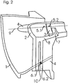
- Fig. 2 shows the cut out lower, seen in the flow direction of a fluid to be compressed left, a quarter of an inlet nozzle according to an embodiment the present invention in perspective view, Fig. 1 a horizontal section in Fig. 2 ,
- the inlet nozzle has an inlet housing 1 for collecting and supplying a medium to a turbo-compressor (not shown).
- a bearing housing 2 is arranged, which has a substantially cylindrical shape, with the medium to be compacted in the flow direction (from left to right in the figures), front hemispherical end face.
- a radial bearing 3 for a rotor with impeller of the turbocompressor (not shown) is formed, the bearing center point 3a is located axially in the center of the bearing ring shown.
- the bearing housing 2 is connected to the inlet housing 1 via three, four or more inlet struts, wherein in Fig. 2 a lower (cut) and a left (partially hidden) inlet strut 4 are visible, in Fig. 1 the left inlet strut 4.
- two or more blind struts are additionally arranged in the upper half of the inlet housing, which are not connected to the bearing housing.
- left inlet strut 4 is integrally connected to the inlet housing 1 and is in its the inlet housing 1 facing end cross section in this over.
- the center of area 10 of this end cross-section is in Fig. 1 drawn and is located axially in front of the bearing center point 3a, which in relation to this area center point by the 0.375-fold in the flow direction of a fluid to be compressed axially to the rear (to the right in Fig. 1 ) is offset.
- Fig. 1 left front fluid passage 5.1 (dash-dot in Fig. 1 ) serves the guidance of lines for sensors to the bearing 3 and in the vicinity of the bearing 3 before this opens into the bearing housing 2
- a middle fluid passage 5.2 (drawn in Fig. 1 ) the supply of lubricant to the bearing 3 and opens in the bearing 3 in the bearing housing 2
- a in Fig. 1 right, rear fluid passage 5.3 (double-dashed in Fig. 1 ) serves the supply of sealing air into the bearing housing 2 and opens in the vicinity of the bearing 3 after this in the bearing housing 2.
- These fluid passages 5 are formed as through-holes and therefore extend substantially straight. They close an acute angle of about 23 ° with a normal plane to the longitudinal axis of the inlet nozzle (vertical plane perpendicular to the plane of the drawing Fig. 1 ) or the complementary angle of about 67 ° with the longitudinal axis.
- two fluid passages 6 are formed, which serve for the removal of lubricant from the interior of the bearing housing 2.
- These fluid passages 6 form sections an acute angle with a normal plane to the longitudinal axis of the inlet nozzle. For this purpose, they have a kinked course, wherein in each case a substantially extending in the radial direction portion 61 and 6.2 merges into a two fluid passages 6 common portion 8, which forms an acute angle of about 72 ° with a normal plane to the longitudinal axis of the inlet nozzle ,
- This common inclined section 8 extends in the longitudinal direction of the inlet housing 1 (from left to right in FIG Fig. 1 ) and ends at the end in a circular segment-shaped annular groove 7, which is formed at right angles to the section 8 and extends over a range of 70 ° in the lower half of the bearing housing 2.
- a circular segment-shaped annular groove 7 which is formed at right angles to the section 8 and extends over a range of 70 ° in the lower half of the bearing housing 2.
- common open portion 8 which extends from the annular groove 7 below the radial bearing 3 forward through to the extending in the radial direction sections 6.1, 6.2, communicate the two fluid passages with the interior of the bearing housing. 2
- the inlet struts 4 extend substantially in the radial direction (from top to bottom in FIG Fig. 1 ).
- the inlet struts 4 at their in the flow direction of the fluid to be compressed (right in Fig. 1 . 2 ) rear trailing edge a substantially dreickförmigen approach 4.1.
- a radial axis through the surface centers of the inlet struts 4 therefore has in this section with the paragraph 4.1 at an acute angle with a normal plane to the longitudinal axis of the inlet nozzle.
Landscapes
- Engineering & Computer Science (AREA)
- Mechanical Engineering (AREA)
- General Engineering & Computer Science (AREA)
- Physics & Mathematics (AREA)
- Fluid Mechanics (AREA)
- Structures Of Non-Positive Displacement Pumps (AREA)
Description
Die Erfindung betrifft einen Eintrittsstutzen für einen Axialverdichter, insbesondere einen Turbokompressor, mit einem Eintrittsgehäuse, in dem ein Lagergehäuse mit einem in Strömungsrichtung eines zu verdichtenden Fluids axial ersten Lager für einen Rotor des Axialverdichters angeordnet ist, wobei das Lagergehäuse mit dem Eintrittsgehäuse über eine Einlaufstrebe verbunden ist, die in einem Stirnquerschnitt mit dem Eintrittsgehäuse verbunden ist.The invention relates to an inlet connection for an axial compressor, in particular a turbocompressor, with an inlet housing, in which a bearing housing is arranged with a first fluid axially in the flow direction of a fluid to be compressed bearing for a rotor of the axial compressor, wherein the bearing housing connected to the inlet housing via an inlet strut is, which is connected in an end cross section with the inlet housing.
Solche Einlaufstreben verlaufen bei herkömmlichen Axialverdichtern rein radial, i.e. parallel zu einer Normalebene zur Längsachse des Eintrittsstutzens, so dass der Lagermittelpunkt des ersten bzw. vorderen Lagers in Strömungsrichtung eines zu verdichtenden Fluids axial im Wesentlichen auf Höhe des Flächenmittelpunktes dieses Stirnquerschnittes angeordnet ist, mit anderen Worten das Lager axial mittig in der Einlaufstrebe unter dessen Übergang in das Eintrittsgehäuse angeordnet ist.Such intake struts are purely radial in conventional axial compressors, ie. parallel to a normal plane to the longitudinal axis of the inlet nozzle, so that the bearing center of the first or front bearing is arranged axially in the flow direction of a fluid to be compressed substantially at the level of the center of area of this end cross-section, in other words the bearing axially centrally in the inlet strut under the transition is arranged in the inlet housing.
Als Lagermittepunkt wird vorliegend insbesondere ein Durchstoßpunkt einer Lagerachse durch eine Symmetrieebene eines symmetrischen Lagers, ein Massenmittelpunkt des Lagers, der geometrische Mittelpunkt zwischen den axialen Stirnseiten des Lagers oder ein Druckpunkt des Lagers bezeichnet.In particular, a piercing point of a bearing axis through a plane of symmetry of a symmetrical bearing, a center of mass of the bearing, the geometric center between the axial end faces of the bearing or a pressure point of the bearing are referred to as the bearing center point.
Da die Einlaufstreben insbesondere aus Festigkeits-und Fertigungsgründen häufig axial relativ weit vorne zum Eintrittsquerschnitt des Eintrittsstutzens hin mit dem Eintrittsgehäuse verbunden sind, um sich beispielsweise gegen entsprechende Verstärkungen des Eintrittsgehäuses abstützen zu können oder beim Urformen stark variierende Wandstärken zu vermeiden, ist damit auch das erste bzw. vordere Lager entsprechend weit vorne angeordnet, so dass sich ein relativ großer Lagerabstand zu einem zweiten, hinteren Lager des Rotors des Axialverdichters ergibt, das in Strömungsrichtung hinter dem ersten Lager angeordnet ist.Since the inlet struts, in particular for reasons of strength and production, are often connected relatively far forward to the inlet cross-section of the inlet connection with the inlet housing in order to be able to support, for example, against corresponding reinforcements of the inlet housing or to avoid greatly varying wall thicknesses during prototyping, this is also the first one or front bearing arranged correspondingly far forward, so that there is a relatively large bearing distance to a second, rear bearing of the rotor of the axial compressor, which is arranged in the flow direction behind the first bearing.
In der Einlaufstreben können eine oder mehrere Fluidpassagen ausgebildet sein. Solche Fluidpassagen können beispielsweise der Schmierung des Lagers dienen und hierzu einerseits im oder in der Nähe des Lagers in das Lagergehäuse münden und andererseits mit einer Schmiermittelver- bzw. -entsorgung, beispielsweise über Schmiernippel, Leitungen, Passagen in angrenzenden Gehäuseteilen oder dergleichen, außerhalb des Eintrittsgehäuses verbunden sein. Um dabei sowohl die Länge der Fluidpassage und damit die Schwächung der das Lagergehäuse tragenden Einlaufstrebe als auch den Aufwand zu ihrer - in der Regel spanenden - Herstellung zu minimieren, verlaufen solche Fluidpassagen bisher im Wesentlichen radial.
Dies führt dazu, dass ein von der radialen Fluidpassage versorgten Lager axial auf Höhe der Austrittsöffnung der Fluidpassage aus dem Eintrittsgehäuse angeordnet werden muss, was den Lagermittenabstand des Rotors ebenfalls nachteilig vergrößert.
Ein größerer Lagermittenabstand kann jedoch die Rotordynamik negativ beeinflussen.In the inlet struts, one or more fluid passages may be formed. Such fluid passages can serve, for example, the lubrication of the bearing and for this purpose open into the bearing housing on the one hand in or near the bearing and on the other hand with a Schmiermittelver- or disposal, for example via grease nipples, lines, passages in adjacent housing parts or the like, be connected outside of the inlet housing. In order to minimize both the length of the fluid passage and thus the weakening of the bearing housing supporting the inlet strut and the effort to their - usually cutting - production, such fluid passages are so far essentially radially.
As a result, a bearing supplied by the radial fluid passage has to be arranged axially at the level of the outlet opening of the fluid passage from the inlet housing, which also disadvantageously increases the bearing center distance of the rotor.
However, a larger bearing center distance can adversely affect the rotor dynamics.
Aus der
Aufgabe der vorliegenden Erfindung ist es daher, einen verbesserten Eintrittsstutzen zur Verfügung zu stellen.
Zur Lösung dieser Aufgabe ist ein Eintrittsstutzen nach dem Oberbegriff des Anspruchs 1 durch wenigstens eines seiner kennzeichnenden Merkmale weitergebildet. Anspruch 15 stellt einen Axialverdichter mit einem solchen Eintrittsstutzen unter Schutz, die Unteransprüche betreffen vorteilhafte Weiterbildungen.
Ein erfindungsgemäßer Eintrittsstutzen ist für einen Axialverdichter, insbesondere einen Turbokompressor, vorgesehen und kann bevorzugt lösbar oder fest mit diesem verbunden oder integral ausgebildet sein. Er weist ein Eintrittsgehäuse auf, dessen Innenraum sich bevorzugt in Strömungsrichtung eines zu verdichtenden Fluides verjüngt. In dem Eintrittsgehäuse ist ein Lagergehäuse angeordnet, welches ein vorderes bzw. erstes Lager für einen Rotor des Axialverdichters aufnimmt. Dabei kann es sich insbesondere um ein Radiallager, ein Axiallager oder ein Radial-Axial-Lager handeln. Dieses Lager ist in Strömungsrichtung eines zu verdichtenden Fluids axial ein erstes, i.e. vorderes Lager, wobei der Rotor in weiteren Lagern abgestützt sein kann, die einen größeren axialen Abstand zu einem Eintrittsquerschnitt des Eintrittsstutzens aufweisen.From the
Object of the present invention is therefore to provide an improved inlet nozzle available.
To solve this problem, an inlet nozzle according to the preamble of
An inlet connection according to the invention is provided for an axial compressor, in particular a turbocompressor, and may preferably be detachably or fixedly connected or integrally formed therewith. It has an inlet housing, the interior of which preferably tapers in the flow direction of a fluid to be compressed. In the inlet housing, a bearing housing is arranged, which receives a front or first bearing for a rotor of the axial compressor. This may in particular be a radial bearing, a thrust bearing or a radial-axial bearing. This bearing is axially in the flow direction of a fluid to be compressed, a first, ie front bearing, wherein the rotor in further Bearings can be supported, which have a greater axial distance to an inlet cross-section of the inlet nozzle.
Das Lagergehäuse ist in dem Eintrittsgehäuse über eine oder mehrere Einlaufstreben abgestützt. Mehrere Einlaufstreben können äquidistant über dem Umfang des Lagergehäuses verteilt sein oder unterschiedliche Winkelabstände zueinander aufweisen. Während äquidistant verteilte Einlaufstreben die Strömung im Lagergehäuse homogen und somit wenig stören, können Einlaufstreben mit unterschiedlichen Winkelabständen zueinander an konstruktive Randbedingungen des Gehäuses, insbesondere außenliegende Zuleitungen, Rippen, unterschiedliche Wandstärken oder dergleichen angepasst werden.The bearing housing is supported in the inlet housing via one or more inlet struts. Several inlet struts can be distributed equidistantly over the circumference of the bearing housing or have different angular distances from each other. While equidistantly distributed inlet struts the flow in the bearing housing homogeneous and thus little disturbing, inlet struts with different angular distances to each other can be adapted to constructional boundary conditions of the housing, in particular external leads, ribs, different wall thicknesses or the like.
Eine oder mehrere Einlaufstreben sind in je einem Stirnquerschnitt der entsprechenden Einlaufstrebe mit dem Eintrittsgehäuse verbunden. Insbesondere können eine oder mehrere, bevorzugt alle Einlaufstreben einstückig, beispielsweise durch Urformen, mit dem Eintritts- und/oder Lagergehäuse verbunden sein. Gleichermaßen können eine oder mehrere Einlaufstreben aber auch nach dem Urformen mit dem Eintritts- und/oder Lagergehäuse verbunden, beispielsweise verschweißt oder verschraubt werden. Erfindungsgemäß ist in wenigstens einer Einlaufstreben eine Fluidpassage ausgebildet. Diese kann insbesondere zum Zuführen und/oder Abführen von Schmiermittel zu dem Lager für das Laufrad vorgesehen sein. Eine Fluidpassage kann gleichermaßen zum Zuführen und/oder Abführen von Kühlfluid, insbesondere Kühlluft, und/oder einem Sperrfluid, insbesondere Sperrluft dienen, um den Axialverdichter zu kühlen bzw. einen Schmiermittelaustritt in den Axialverdichter zu vermeiden. Auch andere Fluide, beispielsweise ein Hydraulikfluid, insbesondere eines geregelten Lagers, können durch die Fluidpassage strömen. Insbesondere zu den vorgenannten Funktionen kann eine Fluidpassage in einer bevorzugten Ausführung in oder in der Nähe des Lagers in das Lagergehäuse münden. Zusätzlich oder alternativ zu einem Fluid kann die insoweit nur zur Vereinfachung so bezeichnete Fluidpassage beispielsweise auch zur Führung von Kabeln, Leitungen oder dergleichen, etwa elektrischer und/oder optischer Leitungen für Sensoren im Lagergehäuse ausgebildet sein.One or more inlet struts are connected in each case an end cross section of the corresponding inlet strut with the inlet housing. In particular, one or more, preferably all inlet struts may be integrally connected to the inlet and / or bearing housing, for example by primary molding. Similarly, one or more inlet struts can also be connected to the entry and / or bearing housing after the prototyping, for example welded or screwed. According to the invention, a fluid passage is formed in at least one inlet struts. This can be provided in particular for supplying and / or removing lubricant to the bearing for the impeller. A fluid passage can likewise serve for supplying and / or removing cooling fluid, in particular cooling air, and / or a blocking fluid, in particular blocking air, in order to cool the axial compressor or to avoid a lubricant outlet into the axial compressor. Other fluids, such as a hydraulic fluid, in particular a controlled bearing, can flow through the fluid passage. In particular to the aforementioned functions, a fluid passage in a preferred embodiment in or in the vicinity of the bearing can open into the bearing housing. In addition or as an alternative to a fluid, the fluid passage described so far only for the sake of simplification may, for example, also be designed to guide cables, lines or the like, for example electrical and / or optical lines for sensors in the bearing housing.
Erfindungsgemäß wird vorgeschlagen, dass eine Fluidpassage wenigstens abschnittsweise einen spitzen Winkel mit einer Normalebene zur Längsachse des Eintrittsstutzens einschließt, i.e. schräg zur Axialrichtung des Eintrittsstutzens verläuft, insbesondere von radial außen nach radial innen in Strömungsrichtung des zu verdichtenden Fluides.
Durch diese konstruktive Abänderung gegenüber herkömmlichen, rein radial verlaufenden Fluidpassagen wird es vorteilhaft möglich, das Lager in Strömungsrichtung des zu verdichtenden Fluides axial nach hinten zu versetzen so den Lagermittenabstand zu verkürzen, um rotordynamische Probleme zu verringern oder zu vermeiden. Gleichzeitig wird es möglich, Zuleitungen zu den Fluidpassagen an der Außenfläche des Eintrittsgehäuses optimal, beispielsweise in Strömungsrichtung des zu verdichtenden Fluides weiter vorne anzuordnen und somit im Bereich der Einlaufstrebe(n) Verstärkungen wie Rippen oder dergleichen an der Außenfläche des Eintrittsgehäuses vorzusehen.
Der Lagermittelpunkt des ersten Lagers ist in Strömungsrichtung eines zu verdichtenden Fluids axial wenigstens um das 0,1-fache, bevorzugt wenigstens um das 0,15-fach, weiter bevorzugt wenigstens um das 0,2-fache und insbesondere wenigstens um das 0,25-fache der Sehnenlänge des Stirnquerschnittes hinter dem Flächenmittelpunkt des Stirnquerschnittes angeordnet. Als Sehnenlänge wird dabei die maximale Erstreckung des Stirnquerschnittes in axialer Richtung, i.e. in Strömungsrichtung eines zu verdichtenden Fluids bezeichnet, die beispielsweise bei einem kreisförmigen Stirnquerschnitt dessen Durchmesser, bei einem ellipsenförmigen Stirnquerschnitt dessen großem Halbmesser entspricht.Das erste Lager ist hinter dem Flächenmittelpunkt eines Stirnquerschnittes angeordnet. Hierdurch wird vorteilhaft der Lagerabstand zum Massenmittelpunkt des Rotors und - sofern vorhanden - zu einem zweiten, hinteren Lager des Rotors des Axialverdichters verkürzt, das in Strömungsrichtung hinter dem ersten Lager angeordnet ist.
Dabei kann das erste Lager insbesondere hinter den ersten zwei Dritteln der Sehnenlänge, i.e. wenigstens um das 0,17-fach, bevorzugt hinter den ersten drei Vierteln der Sehnenlänge, i.e. wenigstens um das 0,25-fach hinter dem Flächenmittelpunkt des Stirnquerschnittes angeordnet sein.According to the invention, it is proposed that a fluid passage at least partially encloses an acute angle with a normal plane to the longitudinal axis of the inlet nozzle, ie obliquely to the axial direction of the inlet nozzle, in particular from radially outside to radially inside in the direction of flow of the fluid to be compressed.
This constructive change compared to conventional, purely radially extending fluid passages, it is advantageously possible to move the bearing in the flow direction of the fluid to be compressed axially backwards so shorten the bearing center distance to reduce rotor dynamic problems or to avoid. At the same time, it becomes possible to optimally arrange feed lines to the fluid passages on the outer surface of the inlet housing, for example in the flow direction of the fluid to be compressed, and thus to provide reinforcements such as ribs or the like on the outer surface of the inlet housing in the area of the inlet strut (s).
The bearing center of the first bearing is in the flow direction of a fluid to be compressed axially at least 0.1 times, preferably at least 0.15 times, more preferably at least 0.2 times and in particular at least 0.25 -fold the chord length of the end cross-section disposed behind the center of area of the end cross-section. In this case, the chord length is the maximum extent of the end cross-section in the axial direction, ie in the flow direction of a fluid to be compressed, which corresponds, for example, to its diameter in the case of a circular end cross-section, and to its large radius in the case of an elliptical cross-section. The first bearing is arranged behind the center of area of an end cross-section , This advantageously the bearing distance to the center of mass of the rotor and - if present - shortened to a second, rear bearing of the rotor of the axial compressor, which is arranged downstream of the first bearing in the flow direction.
In this case, the first bearing, in particular behind the first two thirds of the chord length, ie at least 0.17-fold, preferably after the first three quarters of the chord length, ie be arranged at least 0.25-fold behind the center of area of the end cross-section.
Ist das Lagergehäuse über mehrere Einlaufstreben mit dem Eintrittsgehäuse verbunden, ist der Lagermittelpunkt des ersten Lagers axial wenigstens um das 0,1-fache, 0,15-fach, 0,2- fache bzw. 0,25-fache der Sehnenlänge des Stirnquerschnittes hinter dem Flächenmittelpunkt des Stirnquerschnittes wenigstens einer Einlaufstrebe angeordnet. Es können also auch Einlaufstreben vorhanden sein, bezüglich deren Stirnquerschnitt das erste Lager axial vor oder im Flächenmittelpunkt angeordnet ist. In einer bevorzugten Weiterbildung ist der Lagermittelpunkt des ersten Lagers axial wenigstens um das 0,1-fache, 0,15-fach, 0,2-fache bzw. 0,25-fache der Sehnenlänge des Stirnquerschnittes hinter den Flächenmittelpunkten der Stirnquerschnitte aller Einlaufstreben angeordnet.If the bearing housing is connected to the inlet housing via a plurality of inlet struts, the bearing center of the first bearing is axially behind at least 0.1 times, 0.15 times, 0.2 times or 0.25 times the chord length of the end cross section arranged the surface center of the end cross-section of at least one inlet strut. Thus, it is also possible for inlet struts to be present, with respect to whose end cross-section the first bearing is arranged axially in front of or in the center of the surface. In a preferred embodiment, the bearing center of the first bearing is arranged axially at least 0.1 times, 0.15 times, 0.2 times or 0.25 times the chord length of the end cross section behind the surface centers of the end cross sections of all inlet struts ,
Der Lagermittelpunkt muss nicht mehr innerhalb der auf die Längsachse des Eintrittsstutzens projizierten Sehnenlänge des bzw. der Stirnquerschnitte liegen, sondern kann axial auch hinter dem bzw. den Stirnquerschnitten angeordnet sein. Gleichermaßen kann er jedoch auch innerhalb der auf die Längsachse des Eintrittsstutzens projizierten Sehnenlänge des bzw. der Stirnquerschnitte liegen, insbesondere höchstens um das 0,75-fache, insbesondere höchstens um das 0,5-fache der Sehnenlänge des Stirnquerschnittes hinter dem Flächenmittelpunkt des Stirnquerschnittes angeordnet sein.The bearing center no longer has to lie within the chord length of the end section (s) projected onto the longitudinal axis of the entry socket, but can also be arranged axially behind the end section (s). Equally, however, it can also be located within the chord length of the end cross section projected onto the longitudinal axis of the entry stub, in particular at most 0.75 times, in particular at most 0.5 times the chord length of the end cross section behind the center of the face cross section be.
Wenn das erste Lager gegenüber dem Stirnquerschnitt einer Einlaufstrebe axial nach hinten versetzt ist, kann es durch schräg verlaufende Fluidpassagen in dieser Einlaufstrebe besonders gut bedient werden.If the first bearing is offset axially to the rear relative to the end cross-section of an inlet strut, it can be operated particularly well by obliquely extending fluid passages in this inlet strut.
In einer oder mehreren Einlaufstreben können jeweils mehrere, insbesondere zwei oder drei Fluidpassagen ausgebildet sein, wobei wenigstens eine, bevorzugt mehrere, besonders bevorzugt alle Fluidpassagen einen spitzen Winkel mit einer Normalebene zur Längsachse des Eintrittsstutzens bilden. Solche Fluidpassagen können bevorzugt im Wesentlichen parallel zueinander verlaufen, was die Fertigung vereinfacht. Gleichermaßen können sie jedoch auch unterschiedliche Winkel mit der Normalebene einschließen, um so insbesondere optimale Wege zwischen Austrittspositionen am Eintrittsgehäuse und am Lagergehäuse zu definieren. Auf diese Weise können beispielsweise nahe beieinander in das Lagergehäuse mündende Fluidpassagen mit axial voneinander entfernten Zuleitungen am Eintrittsgehäuse verbunden werden und umgekehrt.In each case several, in particular two or three fluid passages can be formed in one or more inlet struts, wherein at least one, preferably several, particularly preferably all fluid passages form an acute angle with a normal plane to the longitudinal axis of the inlet nozzle. Such fluid passages may preferably run substantially parallel to one another, which is the production simplified. Likewise, however, they may also include different angles with the normal plane so as to define in particular optimal paths between exit positions on the inlet housing and on the bearing housing. In this way, for example, fluid passages opening into the bearing housing close to one another can be connected to supply lines at the inlet housing that are axially remote from one another, and vice versa.
In zwei Einlaufstreben kann eine unterschiedliche Anzahl von Fluidpassagen ausgebildet sein, um so beispielsweise Zu- und Ableitungen optimal zu verteilen. Auch müssen Fluidpassagen in derselben oder unterschiedlichen Einlaufstreben nicht denselben Durchmesser aufweisen, sondern können beispielsweise an die Beschaffenheit und Menge des zu- oder abgeführten Mediums angepasst sein.In two inlet struts, a different number of fluid passages may be formed so as to optimally distribute, for example, supply and discharge lines. Also fluid passages in the same or different inlet struts need not have the same diameter, but may, for example, be adapted to the nature and quantity of the added or discharged medium.
Eine oder mehrere Fluidpassagen können im Wesentlichen geradlinig verlaufen, so dass sie überall denselben spitzen Winkel mit einer Normalebene zur Längsachse des Eintrittsstutzens bilden. Solche Fluidpassagen sind besonders einfach durch Bohren herzustellen und in der Konstruktion zu berücksichtigen.One or more fluid passages may be substantially rectilinear so as to form the same acute angle everywhere with a normal plane to the longitudinal axis of the inlet nozzle. Such fluid passages are particularly easy to produce by drilling and to consider in the design.
Der Winkel, den eine solche im Wesentlichen geradlinig verlaufende Fluidpassage mit einer Normalebene zur Längsachse des Eintrittsstutzens bildet, kann bevorzugt im Bereich zwischen 10° und 40°, insbesondere im Bereich zwischen 20° und 30° liegen. Dies stellt einen guten Kompromiss aus Verkürzung des Lagermittenabstandes und Erhöhung des Fertigungsaufwandes dar.The angle formed by such a substantially rectilinear fluid passage with a normal plane to the longitudinal axis of the inlet nozzle can preferably be in the range between 10 ° and 40 °, in particular in the range between 20 ° and 30 °. This represents a good compromise from shortening the bearing center distance and increasing the manufacturing effort.
Eine oder mehrere Fluidpassagen können auch einen geknickten Verlauf aufweisen, so dass wenigstens ein Abschnitt dieser Fluidpassage einen spitzen Winkel mit einer Normalebene zur Längsachse des Eintrittsstutzens bildet. Andere Abschnitte solcher Fluidpassagen können hingegen beispielsweise im Wesentlichen in Radialrichtung des Eintrittsgehäuses verlaufen. Auf diese Weise können die Vorteile rein radialer und schräg verlaufender Fluidpassagen miteinander verbunden werden.One or more fluid passages may also have a kinked profile, so that at least a portion of this fluid passage forms an acute angle with a normal plane to the longitudinal axis of the inlet nozzle. By contrast, other sections of such fluid passages, for example, can extend substantially in the radial direction of the inlet housing. In this way, the advantages of purely radial and inclined fluid passages can be interconnected.
Der Winkel, den ein solcher schräger Abschnitt einer Fluidpassage mit geknicktem Verlauf mit einer Normalebene zur Längsachse des Eintrittsstutzens bildet, liegt bevorzugt im Bereich zwischen 60° und 80°, insbesondere im Bereich zwischen 65° und 75°. Da hier nur eine kürzere Strecke in radialer Richtung zum Ausgleich des Axialversatzes zwischen Ein- und Austritt der Fluidpassage zur Verfügung steht, weisen solche schrägen Abschnitte bevorzugt größere Winkel zur Normalebene auf als knicklose Fluidpassagen.The angle which forms such an oblique section of a fluid passage with a bent course with a normal plane to the longitudinal axis of the inlet nozzle is preferably in the range between 60 ° and 80 °, in particular in the range between 65 ° and 75 °. Since here only a shorter distance in the radial direction to compensate for the axial offset between inlet and outlet of the fluid passage available stands, such oblique sections preferably have larger angles to the normal plane than kinkless fluid passages.
In einer bevorzugten Ausführung münden zwei oder mehr Fluidpassagen in einen gemeinsamen Abschnitt, der mit dem Inneren des Lagergehäuses kommuniziert. Dieser Abschnitt kann insbesondere schräg verlaufen, während die in ihn mündenden Fluidpassagen bevorzugt im Wesentlichen in Radialrichtung des Eintrittsgehäuses verlaufen. Hierdurch können von solchen, im Wesentlichen rein radial verlaufenden, Fluidpassagen ver- oder entsorgte Stellen durch einen gemeinsamen schrägen Abschnitt beschickt werden, was den Herstellungsaufwand und die Schwächung der Einlaufstrebe vorteilhaft verringert.In a preferred embodiment, two or more fluid passages open into a common portion that communicates with the interior of the bearing housing. In particular, this section may extend obliquely, while the fluid passages opening into it preferably extend essentially in the radial direction of the inlet housing. As a result of such, substantially purely radially extending, fluid passages ver- or disposed points can be fed through a common inclined section, which advantageously reduces the production cost and the weakening of the inlet strut.
Eine Radialachse durch die Flächenmittel- oder -schwerpunkte wenigstens einer Einlaufstrebe kann - wenigstens abschnittsweise - ebenfalls einen spitzen Winkel mit einer Normalebene zur Längsachse des Eintrittsstutzens bilden Hierzu kann beispielsweise eine Einlaufstrebe mit konstantem Querschnitt insgesamt schräg, insbesondere in Strömungsrichtung eines zu verdichtenden Fluides zum Lagergehäuse hin zulaufend, ausgebildet sein. Eine solche gepfeilte Einlaufstrebe ist zur Aufnahme insbesondere geradliniger Fluidpassagen besonders geeignet. Insbesondere zu deren Aufnahme, aber auch zur Aufnahme von geknickten Fluidpassagen sowie zur Abstützung eines axial nach hinten versetzten ersten Lagers kann eine Einlaufstrebe gleichermaßen auch im Wesentlichen in radialer Richtung des Eintrittsgehäuses verlaufen und sich zum Lagergehäuse hin verbreitern, so dass der Flächenmittel- oder -schwerpunkt sich zum Lagergehäuse hin in Strömungsrichtung eines zu verdichtenden Fluides nach hinten verlagert.A radial axis through the center of area or center of gravity of at least one inlet strut can also - at least in sections - form an acute angle with a normal plane to the longitudinal axis of the inlet nozzle. For example, an inlet strut having a constant cross section can be inclined overall, in particular in the direction of flow of a fluid to be compressed towards the bearing housing tapering, be formed. Such a swept inlet strut is particularly suitable for receiving in particular straight-line fluid passages. In particular, for their inclusion, but also for receiving kinked fluid passages and for supporting an axially rearwardly displaced first bearing, an inlet strut can also extend substantially in the radial direction of the inlet housing and widen towards the bearing housing, so that the center of area or center of gravity displaced towards the bearing housing in the flow direction of a fluid to be compressed to the rear.
Weitere Vorteile und Merkmale ergeben sich aus den Unteransprüchen und den nachfolgenden Ausführungsbeispielen. Hierzu zeigt, teilweise schematisiert:
-
Fig. 1 einen Eintrittsstutzen nach einer Ausführung der vorliegenden Erfindung im Halbschnitt; und -
Fig. 2 den Eintrittsstutzen nachFig. 1 im perspektivischen Viertelschnitt.
-
Fig. 1 an inlet nozzle according to an embodiment of the present invention in half section; and -
Fig. 2 after the inlet pipeFig. 1 in perspective quarter section.
Der Eintrittsstutzen weist ein Eintrittsgehäuse 1 zum Sammeln und Zuführen eines Mediums zu einem (nicht dargestellten) Turbokompressor dar. In dem Eintrittsgehäuse 1 ist ein Lagergehäuse 2 angeordnet, das eine im Wesentlichen zylindrische Form, mit in Strömungsrichtung des zu verdichtenden Mediums (von links nach rechts in den Figuren), vorderer halbkugelförmiger Stirnseite aufweist. In dem Lagergehäuse 2 ist ein Radiallager 3 für einen Rotor mit Laufrad des Turbokompressors (nicht dargestellt) ausgebildet, dessen Lagermittelpunkt 3a axial in der Mitte des dargestellten Lagerringes liegt.The inlet nozzle has an
Das Lagergehäuse 2 ist mit dem Eintrittsgehäuse 1 über drei, vier oder mehrere Einlaufstreben verbunden, wobei in
In einer nicht dargestellten Abwandlung sind zusätzlich zwei oder mehr Blindstreben in der oberen Hälfte des Eintrittsgehäuses angeordnet, welche nicht mit dem Lagergehäuse verbunden sind.In a modification, not shown, two or more blind struts are additionally arranged in the upper half of the inlet housing, which are not connected to the bearing housing.
Die in
In der linken Einlaufstrebe 4 sind drei Fluidpassagen 5 ausgebildet, von denen eine in
Diese Fluidpassagen 5 sind als Durchgangsbohrungen ausgebildet und verlaufen daher im Wesentlichen geradlinig. Sie schließen einen spitzen Winkel von ca. 23° mit einer Normalebene zur Längsachse des Eintrittsstutzens (Vertikalebene senkrecht zur Zeichenebene der
In der unteren Einlaufstrebe 4 sind zwei Fluidpassagen 6 ausgebildet, die der Abfuhr von Schmiermittel aus dem Inneren des Lagergehäuses 2 dienen. Diese Fluidpassagen 6 bilden abschnittsweise einen spitzen Winkel mit einer Normalebene zur Längsachse des Eintrittsstutzens. Hierzu weisen sie einen geknickten Verlauf auf, wobei jeweils ein sich im Wesentlichen in radialer Richtung erstreckende Abschnitt 61 bzw. 6.2 in einen beiden Fluidpassagen 6 gemeinsamen Abschnitt 8 übergeht, der einen spitzen Winkel von ca. 72° mit einer Normalebene zur Längsachse des Eintrittsstutzens bildet.In the
Dieser gemeinsame schräge Abschnitt 8 erstreckt sich in Längsrichtung des Eintrittsgehäuses 1 (von links nach rechts in
Auch bezüglich des Flächenmittelpunktes 10 der unteren Einlaufstreben 4 ist der Lagermittelpunkt des Lagers 3, wie in
Wie insbesondere in
- 11
- Eintrittsgehäuseinlet casing
- 22
- Lagergehäusebearing housing
- 33
- Radiallagerradial bearings
- 3a3a
- LagermittelpunktBearing center
- 44
- Einlaufstrebeinlet strut
- 4.14.1
- Ansatzapproach
- 5.1-5.35.1-5.3
- Fluidpassage (für Luft, Schmiermittel bzw. Kabel)Fluid passage (for air, lubricant or cable)
- 6.1, 6.26.1, 6.2
- Fluidpassagefluid passage
- 77
- Ringnutring groove
- 88th
- gemeinsamer Abschnittcommon section
- 99
- Längsachselongitudinal axis
- 1010
- Flächenmittelpunkt des StirnquerschnittesArea center of the end cross-section
Claims (15)
- An inlet connector for an axial compressor, in particular a turbocompressor, with an inlet housing (1), in which a bearing housing (2) with an, in flow direction of a fluid to be compressed, axially first bearing (3), in particular a radial and/or axial bearing, for a rotor is arranged, wherein the bearing housing (2) is connected to the inlet housing (1) via at least one inlet brace (4), which in a front cross section is connected to the inlet housing, wherein in the at least one inlet brace (4) at least one fluid passage (5, 6) is formed, which at least in sections forms an acute angle with a normal plane to the longitudinal axis of the inlet connector, characterized in that the bearing centre point of the bearing (3) in the flow direction is ranged axially at least by 0.1 times the chord length as maximum extension of the front cross section in the axial direction behind the centre of area of the front cross section.
- The inlet connector according to Claim 1, characterized in that the bearing centre point of the bearing (3) in the flow direction is arranged axially at least 0.15-times in particular at least 0.2-times in particular at least 0.25-times of the chord length of the front cross section behind the centre of area of the front cross section.
- The inlet connector according to Claim 1 or 2, characterized in that the bearing housing (2) is connected to the inlet housing (1) via multiple, in particular three or four inlet braces (4).
- The inlet connector according to Claim 3, characterized in that the bearing housing (2) is connected to the inlet housing (1) via three or more evenly or unevenly distributed inlet braces, wherein one or more inlet braces are embodied as blind braces.
- The inlet connector according to any one of the preceding claims, characterized in that in at least one inlet brace (4) multiple, in particular two or three fluid passages (5.1, 5.2, 5.3; 6.1, 6.2) are formed.
- The inlet connector according to Claim 3 and 4, characterized in that in a first inlet brace (4) multiple fluid passages (6.1, 6.2) and in another inlet brace (4) a number of fluid passages (5.1, 5.2, 5.3) that is distinct thereof is formed.
- The inlet connector according to any one of the preceding claims, characterized in that at least one fluid passage (5) extends substantially linearly, so that it forms the same acute angle with a normal plane to the longitudinal axis of the inlet connector everywhere.
- The inlet connector according to Claim 6, characterized in that the angle formed by a substantially linearly extending fluid passage (5) with a normal plane to the longitudinal axis of the inlet connector, is in the range between 10° and 40°, in particular in the range between 20° and 30°.
- The inlet connector according to any one of the preceding claims, characterized in that at least one fluid passage (6) has a folded course, so that at least one section (8) of this fluid passage forms an acute angle with a normal plane to the longitudinal axis of the inlet connector.
- The inlet connector according to Claim 8, characterized in that the angle formed by a section (8) of a fluid passage (6) with folded course with a normal plane to the longitudinal axis of the inlet connector, is in the range between 60° and 80°, in particular in the range between 65° and 75°.
- The inlet connector according to any one of the preceding claims, characterized in that at least two fluid passages (6.1, 6.2) open into a common section (8), which communicates with the interior of the bearing housing (2).
- The inlet connector according to any one of the preceding claims, characterized in that a fluid passage is formed for feeding and/or discharging lubricant to the bearing (3) for the impeller.
- The inlet connector according to any one of the preceding claims, characterized in that a fluid passage (5, 6) opens into the bearing housing (2) in or in the vicinity of the bearing (3).
- The inlet connector according to any one of the preceding claims, characterized in that a radial axis through the centre of areas of at least one inlet brace forms an acute angle with a normal plane to the longitudinal axis of the inlet connector at least in sections.
- An axial compressor, in particular turbocompressor, with an inlet connector according to any one of the preceding claims.
Applications Claiming Priority (2)
| Application Number | Priority Date | Filing Date | Title |
|---|---|---|---|
| DE200810008886 DE102008008886A1 (en) | 2008-02-13 | 2008-02-13 | Inlet nozzle for an axial compressor |
| PCT/EP2008/009254 WO2009100741A1 (en) | 2008-02-13 | 2008-11-03 | Inlet connecting piece for an axial-flow compressor |
Publications (2)
| Publication Number | Publication Date |
|---|---|
| EP2240696A1 EP2240696A1 (en) | 2010-10-20 |
| EP2240696B1 true EP2240696B1 (en) | 2019-01-02 |
Family
ID=40350157
Family Applications (1)
| Application Number | Title | Priority Date | Filing Date |
|---|---|---|---|
| EP08872325.9A Not-in-force EP2240696B1 (en) | 2008-02-13 | 2008-11-03 | Inlet connecting piece for an axial-flow compressor |
Country Status (6)
| Country | Link |
|---|---|
| US (1) | US9004856B2 (en) |
| EP (1) | EP2240696B1 (en) |
| JP (1) | JP5444254B2 (en) |
| CN (1) | CN101952604B (en) |
| DE (1) | DE102008008886A1 (en) |
| WO (1) | WO2009100741A1 (en) |
Families Citing this family (1)
| Publication number | Priority date | Publication date | Assignee | Title |
|---|---|---|---|---|
| DE102008008886A1 (en) | 2008-02-13 | 2009-08-20 | Man Turbo Ag | Inlet nozzle for an axial compressor |
Citations (1)
| Publication number | Priority date | Publication date | Assignee | Title |
|---|---|---|---|---|
| US2648493A (en) * | 1945-10-23 | 1953-08-11 | Edward A Stalker | Compressor |
Family Cites Families (15)
| Publication number | Priority date | Publication date | Assignee | Title |
|---|---|---|---|---|
| GB583469A (en) * | 1943-01-04 | 1946-12-19 | David Macleish Smith | Improvements in turbo compressors |
| US2665549A (en) * | 1949-11-02 | 1954-01-12 | United Aircraft Corp | Compressor drive and fuel supply for gas turbine power plants |
| DE2242734A1 (en) * | 1972-08-31 | 1974-03-21 | Motoren Turbinen Union | STORAGE FOR THERMAL POWER MACHINES |
| EP0122328B1 (en) | 1979-05-14 | 1987-03-25 | OSBORN, Norbert Lewis | Compressor housing for a turbocharger and a method of producing such housing |
| CN1004016B (en) * | 1985-04-01 | 1989-04-26 | 苏舍兄弟有限公司 | The cylindrical outer casing of turbo machine |
| US4868963A (en) * | 1988-01-11 | 1989-09-26 | General Electric Company | Stator vane mounting method and assembly |
| FR2631386A1 (en) * | 1988-05-11 | 1989-11-17 | Snecma | TURBOMACHINE HAVING AN INPUT GRID INCORPORATING OIL PIPING TUBES |
| US5253985A (en) * | 1990-07-04 | 1993-10-19 | Mtu Motoren- Und Turbinen-Union Friedrichshafen Gmbh | Exhaust gas turbocharger having rotor runners disposed in roller bearings |
| US6030176A (en) * | 1995-07-19 | 2000-02-29 | Siemens Aktiengesellschaft | Structural member for an exhaust-gas connection of a turbomachine, in particular a steam turbine, and set of at least two structural members |
| GB2324833B (en) * | 1997-02-22 | 2000-10-04 | Rolls Royce Plc | Gas turbine engine support structure |
| US6330790B1 (en) * | 1999-10-27 | 2001-12-18 | Alliedsignal, Inc. | Oil sump buffer seal |
| IT1318110B1 (en) * | 2000-07-03 | 2003-07-23 | Nuovo Pignone Spa | DISCHARGE AND REFRIGERATION SYSTEM FOR THE CUSHIONS OF AN AGAS TURBINE |
| DE50013694D1 (en) * | 2000-09-08 | 2006-12-14 | Abb Turbo Systems Ag | Fastening device for a filter silencer at the compressor inlet of a turbocharger |
| US7475549B2 (en) * | 2005-08-03 | 2009-01-13 | Hamilton Sundstrand Corporation | Thermal management system for a gas turbine engine |
| DE102008008886A1 (en) | 2008-02-13 | 2009-08-20 | Man Turbo Ag | Inlet nozzle for an axial compressor |
-
2008
- 2008-02-13 DE DE200810008886 patent/DE102008008886A1/en not_active Withdrawn
- 2008-11-03 CN CN2008801271662A patent/CN101952604B/en not_active Expired - Fee Related
- 2008-11-03 JP JP2010546218A patent/JP5444254B2/en not_active Expired - Fee Related
- 2008-11-03 US US12/866,077 patent/US9004856B2/en not_active Expired - Fee Related
- 2008-11-03 EP EP08872325.9A patent/EP2240696B1/en not_active Not-in-force
- 2008-11-03 WO PCT/EP2008/009254 patent/WO2009100741A1/en active Application Filing
Patent Citations (1)
| Publication number | Priority date | Publication date | Assignee | Title |
|---|---|---|---|---|
| US2648493A (en) * | 1945-10-23 | 1953-08-11 | Edward A Stalker | Compressor |
Also Published As
| Publication number | Publication date |
|---|---|
| US9004856B2 (en) | 2015-04-14 |
| DE102008008886A1 (en) | 2009-08-20 |
| JP2011511899A (en) | 2011-04-14 |
| EP2240696A1 (en) | 2010-10-20 |
| WO2009100741A1 (en) | 2009-08-20 |
| JP5444254B2 (en) | 2014-03-19 |
| CN101952604A (en) | 2011-01-19 |
| CN101952604B (en) | 2013-11-06 |
| US20100329861A1 (en) | 2010-12-30 |
Similar Documents
| Publication | Publication Date | Title |
|---|---|---|
| EP2091657B1 (en) | Centrifuge, especially separator, with solid discharge orifices | |
| EP3261894B1 (en) | Pneumatic pump device and metering system and sanding system, comprising a jet pump for flowable material | |
| AT510538B1 (en) | CENTRIFUGAL PUMP | |
| WO2009149798A1 (en) | Collecting chamber and method of production | |
| EP2382393B1 (en) | Side channel blower, in particular secondary air blower for an internal combustion engine | |
| EP1651869B1 (en) | Blade wheel for a pump | |
| WO2016146568A1 (en) | Rotating cleaner | |
| EP3488934A1 (en) | Outlet nozzle for a centrifuge drum | |
| DE102015003224B4 (en) | Self-priming pump | |
| WO2011079892A1 (en) | Submersible pump | |
| EP2240696B1 (en) | Inlet connecting piece for an axial-flow compressor | |
| WO2021009275A1 (en) | Stator for an eccentric screw pump | |
| DE102009020409A1 (en) | Rotary nozzle | |
| EP3009680A1 (en) | Multi-stage centrifugal pump | |
| EP2707629A2 (en) | Apparatus for sealing off a pump space of a rotary piston pump, and rotary piston pump having same | |
| DE19612923B4 (en) | Fan | |
| DE102017100540B4 (en) | Cavity Pump | |
| EP1795758A1 (en) | Impeller for a pump unit and pump unit | |
| DE102004040720B4 (en) | Cavity Pump | |
| DE102014114801B4 (en) | Turbomachine with semi-axial impeller | |
| DE102021126120A1 (en) | screw press | |
| EP2390006B1 (en) | Rotor nozzle | |
| EP3887029B1 (en) | Rotor for a device for mixing powder and liquid, and device for mixing powder and liquid | |
| DE102006050203A1 (en) | Hydraulic machine, particularly water turbine, pumping turbine or pump, has impeller with multiple blades, spiral housing surrounding impeller and traverse ring | |
| DE4445956A1 (en) | Pump for self lubrication roller bearings of turbomachinery |
Legal Events
| Date | Code | Title | Description |
|---|---|---|---|
| PUAI | Public reference made under article 153(3) epc to a published international application that has entered the european phase |
Free format text: ORIGINAL CODE: 0009012 |
|
| 17P | Request for examination filed |
Effective date: 20100505 |
|
| AK | Designated contracting states |
Kind code of ref document: A1 Designated state(s): AT BE BG CH CY CZ DE DK EE ES FI FR GB GR HR HU IE IS IT LI LT LU LV MC MT NL NO PL PT RO SE SI SK TR |
|
| AX | Request for extension of the european patent |
Extension state: AL BA MK RS |
|
| RIN1 | Information on inventor provided before grant (corrected) |
Inventor name: DREYER, KARL-HEINZ Inventor name: LANGE, C. Inventor name: RESSING, HENNING Inventor name: AYNACIOGLU, FIKRI Inventor name: ANDING, DIRK |
|
| DAX | Request for extension of the european patent (deleted) | ||
| STAA | Information on the status of an ep patent application or granted ep patent |
Free format text: STATUS: EXAMINATION IS IN PROGRESS |
|
| 17Q | First examination report despatched |
Effective date: 20171221 |
|
| GRAP | Despatch of communication of intention to grant a patent |
Free format text: ORIGINAL CODE: EPIDOSNIGR1 |
|
| STAA | Information on the status of an ep patent application or granted ep patent |
Free format text: STATUS: GRANT OF PATENT IS INTENDED |
|
| INTG | Intention to grant announced |
Effective date: 20180621 |
|
| GRAS | Grant fee paid |
Free format text: ORIGINAL CODE: EPIDOSNIGR3 |
|
| GRAA | (expected) grant |
Free format text: ORIGINAL CODE: 0009210 |
|
| STAA | Information on the status of an ep patent application or granted ep patent |
Free format text: STATUS: THE PATENT HAS BEEN GRANTED |
|
| AK | Designated contracting states |
Kind code of ref document: B1 Designated state(s): AT BE BG CH CY CZ DE DK EE ES FI FR GB GR HR HU IE IS IT LI LT LU LV MC MT NL NO PL PT RO SE SI SK TR |
|
| REG | Reference to a national code |
Ref country code: GB Ref legal event code: FG4D Free format text: NOT ENGLISH |
|
| REG | Reference to a national code |
Ref country code: CH Ref legal event code: EP Ref country code: AT Ref legal event code: REF Ref document number: 1084738 Country of ref document: AT Kind code of ref document: T Effective date: 20190115 |
|
| REG | Reference to a national code |
Ref country code: DE Ref legal event code: R096 Ref document number: 502008016557 Country of ref document: DE |
|
| REG | Reference to a national code |
Ref country code: IE Ref legal event code: FG4D Free format text: LANGUAGE OF EP DOCUMENT: GERMAN |
|
| RAP2 | Party data changed (patent owner data changed or rights of a patent transferred) |
Owner name: MAN ENERGY SOLUTIONS SE |
|
| REG | Reference to a national code |
Ref country code: NL Ref legal event code: MP Effective date: 20190102 |
|
| REG | Reference to a national code |
Ref country code: LT Ref legal event code: MG4D |
|
| PG25 | Lapsed in a contracting state [announced via postgrant information from national office to epo] |
Ref country code: NL Free format text: LAPSE BECAUSE OF FAILURE TO SUBMIT A TRANSLATION OF THE DESCRIPTION OR TO PAY THE FEE WITHIN THE PRESCRIBED TIME-LIMIT Effective date: 20190102 |
|
| REG | Reference to a national code |
Ref country code: DE Ref legal event code: R081 Ref document number: 502008016557 Country of ref document: DE Owner name: MAN ENERGY SOLUTIONS SE, DE Free format text: FORMER OWNER: MAN DIESEL & TURBO SE, 86153 AUGSBURG, DE |
|
| PG25 | Lapsed in a contracting state [announced via postgrant information from national office to epo] |
Ref country code: FI Free format text: LAPSE BECAUSE OF FAILURE TO SUBMIT A TRANSLATION OF THE DESCRIPTION OR TO PAY THE FEE WITHIN THE PRESCRIBED TIME-LIMIT Effective date: 20190102 Ref country code: NO Free format text: LAPSE BECAUSE OF FAILURE TO SUBMIT A TRANSLATION OF THE DESCRIPTION OR TO PAY THE FEE WITHIN THE PRESCRIBED TIME-LIMIT Effective date: 20190402 Ref country code: SE Free format text: LAPSE BECAUSE OF FAILURE TO SUBMIT A TRANSLATION OF THE DESCRIPTION OR TO PAY THE FEE WITHIN THE PRESCRIBED TIME-LIMIT Effective date: 20190102 Ref country code: PT Free format text: LAPSE BECAUSE OF FAILURE TO SUBMIT A TRANSLATION OF THE DESCRIPTION OR TO PAY THE FEE WITHIN THE PRESCRIBED TIME-LIMIT Effective date: 20190502 Ref country code: LT Free format text: LAPSE BECAUSE OF FAILURE TO SUBMIT A TRANSLATION OF THE DESCRIPTION OR TO PAY THE FEE WITHIN THE PRESCRIBED TIME-LIMIT Effective date: 20190102 Ref country code: ES Free format text: LAPSE BECAUSE OF FAILURE TO SUBMIT A TRANSLATION OF THE DESCRIPTION OR TO PAY THE FEE WITHIN THE PRESCRIBED TIME-LIMIT Effective date: 20190102 Ref country code: PL Free format text: LAPSE BECAUSE OF FAILURE TO SUBMIT A TRANSLATION OF THE DESCRIPTION OR TO PAY THE FEE WITHIN THE PRESCRIBED TIME-LIMIT Effective date: 20190102 |
|
| PG25 | Lapsed in a contracting state [announced via postgrant information from national office to epo] |
Ref country code: LV Free format text: LAPSE BECAUSE OF FAILURE TO SUBMIT A TRANSLATION OF THE DESCRIPTION OR TO PAY THE FEE WITHIN THE PRESCRIBED TIME-LIMIT Effective date: 20190102 Ref country code: GR Free format text: LAPSE BECAUSE OF FAILURE TO SUBMIT A TRANSLATION OF THE DESCRIPTION OR TO PAY THE FEE WITHIN THE PRESCRIBED TIME-LIMIT Effective date: 20190403 Ref country code: HR Free format text: LAPSE BECAUSE OF FAILURE TO SUBMIT A TRANSLATION OF THE DESCRIPTION OR TO PAY THE FEE WITHIN THE PRESCRIBED TIME-LIMIT Effective date: 20190102 Ref country code: IS Free format text: LAPSE BECAUSE OF FAILURE TO SUBMIT A TRANSLATION OF THE DESCRIPTION OR TO PAY THE FEE WITHIN THE PRESCRIBED TIME-LIMIT Effective date: 20190502 Ref country code: BG Free format text: LAPSE BECAUSE OF FAILURE TO SUBMIT A TRANSLATION OF THE DESCRIPTION OR TO PAY THE FEE WITHIN THE PRESCRIBED TIME-LIMIT Effective date: 20190402 |
|
| REG | Reference to a national code |
Ref country code: DE Ref legal event code: R097 Ref document number: 502008016557 Country of ref document: DE |
|
| PG25 | Lapsed in a contracting state [announced via postgrant information from national office to epo] |
Ref country code: EE Free format text: LAPSE BECAUSE OF FAILURE TO SUBMIT A TRANSLATION OF THE DESCRIPTION OR TO PAY THE FEE WITHIN THE PRESCRIBED TIME-LIMIT Effective date: 20190102 Ref country code: DK Free format text: LAPSE BECAUSE OF FAILURE TO SUBMIT A TRANSLATION OF THE DESCRIPTION OR TO PAY THE FEE WITHIN THE PRESCRIBED TIME-LIMIT Effective date: 20190102 Ref country code: CZ Free format text: LAPSE BECAUSE OF FAILURE TO SUBMIT A TRANSLATION OF THE DESCRIPTION OR TO PAY THE FEE WITHIN THE PRESCRIBED TIME-LIMIT Effective date: 20190102 Ref country code: RO Free format text: LAPSE BECAUSE OF FAILURE TO SUBMIT A TRANSLATION OF THE DESCRIPTION OR TO PAY THE FEE WITHIN THE PRESCRIBED TIME-LIMIT Effective date: 20190102 Ref country code: SK Free format text: LAPSE BECAUSE OF FAILURE TO SUBMIT A TRANSLATION OF THE DESCRIPTION OR TO PAY THE FEE WITHIN THE PRESCRIBED TIME-LIMIT Effective date: 20190102 |
|
| PLBE | No opposition filed within time limit |
Free format text: ORIGINAL CODE: 0009261 |
|
| STAA | Information on the status of an ep patent application or granted ep patent |
Free format text: STATUS: NO OPPOSITION FILED WITHIN TIME LIMIT |
|
| 26N | No opposition filed |
Effective date: 20191003 |
|
| PGFP | Annual fee paid to national office [announced via postgrant information from national office to epo] |
Ref country code: DE Payment date: 20191121 Year of fee payment: 12 |
|
| PG25 | Lapsed in a contracting state [announced via postgrant information from national office to epo] |
Ref country code: SI Free format text: LAPSE BECAUSE OF FAILURE TO SUBMIT A TRANSLATION OF THE DESCRIPTION OR TO PAY THE FEE WITHIN THE PRESCRIBED TIME-LIMIT Effective date: 20190102 |
|
| PGFP | Annual fee paid to national office [announced via postgrant information from national office to epo] |
Ref country code: IT Payment date: 20191128 Year of fee payment: 12 |
|
| PG25 | Lapsed in a contracting state [announced via postgrant information from national office to epo] |
Ref country code: TR Free format text: LAPSE BECAUSE OF FAILURE TO SUBMIT A TRANSLATION OF THE DESCRIPTION OR TO PAY THE FEE WITHIN THE PRESCRIBED TIME-LIMIT Effective date: 20190102 |
|
| REG | Reference to a national code |
Ref country code: CH Ref legal event code: PL |
|
| PG25 | Lapsed in a contracting state [announced via postgrant information from national office to epo] |
Ref country code: LI Free format text: LAPSE BECAUSE OF NON-PAYMENT OF DUE FEES Effective date: 20191130 Ref country code: MC Free format text: LAPSE BECAUSE OF FAILURE TO SUBMIT A TRANSLATION OF THE DESCRIPTION OR TO PAY THE FEE WITHIN THE PRESCRIBED TIME-LIMIT Effective date: 20190102 Ref country code: CH Free format text: LAPSE BECAUSE OF NON-PAYMENT OF DUE FEES Effective date: 20191130 Ref country code: LU Free format text: LAPSE BECAUSE OF NON-PAYMENT OF DUE FEES Effective date: 20191103 |
|
| REG | Reference to a national code |
Ref country code: BE Ref legal event code: MM Effective date: 20191130 |
|
| GBPC | Gb: european patent ceased through non-payment of renewal fee |
Effective date: 20191103 |
|
| PG25 | Lapsed in a contracting state [announced via postgrant information from national office to epo] |
Ref country code: GB Free format text: LAPSE BECAUSE OF NON-PAYMENT OF DUE FEES Effective date: 20191103 Ref country code: FR Free format text: LAPSE BECAUSE OF NON-PAYMENT OF DUE FEES Effective date: 20191130 Ref country code: IE Free format text: LAPSE BECAUSE OF NON-PAYMENT OF DUE FEES Effective date: 20191103 |
|
| PG25 | Lapsed in a contracting state [announced via postgrant information from national office to epo] |
Ref country code: BE Free format text: LAPSE BECAUSE OF NON-PAYMENT OF DUE FEES Effective date: 20191130 |
|
| REG | Reference to a national code |
Ref country code: AT Ref legal event code: MM01 Ref document number: 1084738 Country of ref document: AT Kind code of ref document: T Effective date: 20191103 |
|
| PG25 | Lapsed in a contracting state [announced via postgrant information from national office to epo] |
Ref country code: AT Free format text: LAPSE BECAUSE OF NON-PAYMENT OF DUE FEES Effective date: 20191103 |
|
| PG25 | Lapsed in a contracting state [announced via postgrant information from national office to epo] |
Ref country code: CY Free format text: LAPSE BECAUSE OF FAILURE TO SUBMIT A TRANSLATION OF THE DESCRIPTION OR TO PAY THE FEE WITHIN THE PRESCRIBED TIME-LIMIT Effective date: 20190102 |
|
| REG | Reference to a national code |
Ref country code: DE Ref legal event code: R119 Ref document number: 502008016557 Country of ref document: DE |
|
| PG25 | Lapsed in a contracting state [announced via postgrant information from national office to epo] |
Ref country code: MT Free format text: LAPSE BECAUSE OF FAILURE TO SUBMIT A TRANSLATION OF THE DESCRIPTION OR TO PAY THE FEE WITHIN THE PRESCRIBED TIME-LIMIT Effective date: 20190102 Ref country code: HU Free format text: LAPSE BECAUSE OF FAILURE TO SUBMIT A TRANSLATION OF THE DESCRIPTION OR TO PAY THE FEE WITHIN THE PRESCRIBED TIME-LIMIT; INVALID AB INITIO Effective date: 20081103 |
|
| PG25 | Lapsed in a contracting state [announced via postgrant information from national office to epo] |
Ref country code: IT Free format text: LAPSE BECAUSE OF NON-PAYMENT OF DUE FEES Effective date: 20201103 |
|
| PG25 | Lapsed in a contracting state [announced via postgrant information from national office to epo] |
Ref country code: DE Free format text: LAPSE BECAUSE OF NON-PAYMENT OF DUE FEES Effective date: 20210601 |