EP2240048B1 - Ejection device and method for actuating an ejection lever - Google Patents
Ejection device and method for actuating an ejection lever Download PDFInfo
- Publication number
- EP2240048B1 EP2240048B1 EP09705004A EP09705004A EP2240048B1 EP 2240048 B1 EP2240048 B1 EP 2240048B1 EP 09705004 A EP09705004 A EP 09705004A EP 09705004 A EP09705004 A EP 09705004A EP 2240048 B1 EP2240048 B1 EP 2240048B1
- Authority
- EP
- European Patent Office
- Prior art keywords
- ejection
- ejection element
- velocity
- furniture part
- movable
- Prior art date
- Legal status (The legal status is an assumption and is not a legal conclusion. Google has not performed a legal analysis and makes no representation as to the accuracy of the status listed.)
- Active
Links
- 238000000034 method Methods 0.000 title claims description 13
- 238000005259 measurement Methods 0.000 claims description 4
- 230000001133 acceleration Effects 0.000 claims description 3
- 230000001419 dependent effect Effects 0.000 claims 1
- 238000010586 diagram Methods 0.000 description 3
- 239000004606 Fillers/Extenders Substances 0.000 description 1
- 230000005540 biological transmission Effects 0.000 description 1
- 238000003780 insertion Methods 0.000 description 1
- 230000037431 insertion Effects 0.000 description 1
- 238000009434 installation Methods 0.000 description 1
- 230000035939 shock Effects 0.000 description 1
Images


Classifications
-
- A—HUMAN NECESSITIES
- A47—FURNITURE; DOMESTIC ARTICLES OR APPLIANCES; COFFEE MILLS; SPICE MILLS; SUCTION CLEANERS IN GENERAL
- A47B—TABLES; DESKS; OFFICE FURNITURE; CABINETS; DRAWERS; GENERAL DETAILS OF FURNITURE
- A47B88/00—Drawers for tables, cabinets or like furniture; Guides for drawers
- A47B88/40—Sliding drawers; Slides or guides therefor
- A47B88/453—Actuated drawers
- A47B88/46—Actuated drawers operated by mechanically-stored energy, e.g. by springs
- A47B88/463—Actuated drawers operated by mechanically-stored energy, e.g. by springs self-opening
-
- A—HUMAN NECESSITIES
- A47—FURNITURE; DOMESTIC ARTICLES OR APPLIANCES; COFFEE MILLS; SPICE MILLS; SUCTION CLEANERS IN GENERAL
- A47B—TABLES; DESKS; OFFICE FURNITURE; CABINETS; DRAWERS; GENERAL DETAILS OF FURNITURE
- A47B88/00—Drawers for tables, cabinets or like furniture; Guides for drawers
- A47B88/40—Sliding drawers; Slides or guides therefor
- A47B88/453—Actuated drawers
- A47B88/457—Actuated drawers operated by electrically-powered actuation means
-
- E—FIXED CONSTRUCTIONS
- E05—LOCKS; KEYS; WINDOW OR DOOR FITTINGS; SAFES
- E05Y—INDEXING SCHEME RELATING TO HINGES OR OTHER SUSPENSION DEVICES FOR DOORS, WINDOWS OR WINGS AND DEVICES FOR MOVING WINGS INTO OPEN OR CLOSED POSITION, CHECKS FOR WINGS AND WING FITTINGS NOT OTHERWISE PROVIDED FOR, CONCERNED WITH THE FUNCTIONING OF THE WING
- E05Y2201/00—Constructional elements; Accessories therefore
- E05Y2201/40—Motors; Magnets; Springs; Weights; Accessories therefore
- E05Y2201/404—Motors; Magnets; Springs; Weights; Accessories therefore characterised by the function
- E05Y2201/422—Motors; Magnets; Springs; Weights; Accessories therefore characterised by the function for opening
- E05Y2201/426—Motors; Magnets; Springs; Weights; Accessories therefore characterised by the function for opening for the initial opening movement
Definitions
- the present invention relates to an ejection device for a furniture part movably held on a furniture body according to the preamble of claim 1, a piece of furniture having an ejection device according to the preamble of claim 8, and a method of actuating an ejection lever of an ejection device according to the preamble of claim 9.
- Such ejection devices are known per se.
- Exemplary here is the WO 2006/113947 A1 called, is arranged in the ejection device in a furniture body so that with a lever, a movable furniture part from a furniture body at least a piece is pushed out.
- the lever is driven by an electric motor.
- the object of the present invention is therefore to eliminate the above-mentioned disadvantages and to provide an alternative solution to avert a risk of breakage of the lever during the operation of the movable furniture part.
- an ejection device for movably held on a furniture body furniture part with the features of the characterizing part of claim 1, a piece of furniture with the features of the characterizing part of claim 8 and by a method having the features of the characterizing part of claim 9.
- the speed measuring device preferably has a position sensor and a timer coupled thereto.
- the timer can be integrated into the control of the electric motor by software, so that an additional component can be dispensed with here.
- the position sensor is arranged on the furniture body such that it detects the position of the ejection lever.
- an action of the movable furniture part can be detected directly on the ejection lever and follow-up actions are controlled.
- top, bottom, left, right, front, back, etc. refer exclusively to the exemplary representation and position of the ejection device, the furniture and other objects selected in the respective figures. These terms are not meant to be limiting, that is, in different working positions or by mirror-symmetrical design or the like, these references may change.
- a piece of furniture 1 comprises a box-shaped furniture body 2, on which one or more drawers 3 are held displaceably.
- 3 extenders 4 are provided on the side of the drawer, which are fixed to the respective side of the furniture body 2.
- the movable furniture part is formed instead of the drawer as movable on the furniture body 2 furniture door.
- an ejection device 6 Adjacent to a rear wall 5 of the drawer 3, an ejection device 6 according to the invention is provided with an ejection element.
- the ejection element is preferably designed as an ejection lever or ejection plunger.
- the ejection device 6 is held on a vertical bar 9, are guided on the electrical lines for power supply.
- the opening of the drawer 3 is supported by the electromotive ejection device 6, which has an ejection lever 10 and a control unit for controlling the electric motor 11.
- the furniture body 3 movably held on the furniture body 2 is at least partially expelled from the furniture body 2 by the ejection lever 10 during normal operation after touching a control panel on the front side of the furniture part, wherein the ejection lever 10 then slowly back to its original position by the electric motor is being reduced.
- the ejection device further comprises a speed measuring device for the direct or indirect determination of a current insertion speed of the movable furniture part 3.
- This speed measuring device preferably has a position sensor 7 and a timer 15 directly or indirectly coupled thereto.
- the position sensor is preferably positioned on the furniture body 2 so as to detect the position of the ejection lever 10 or the movable furniture part 3. In another embodiment (not shown), the position sensor is so on a housing the ejection device 6 is arranged to detect the position of the ejection lever 10 or the movable furniture part 3.
- the position sensor is preferably designed as a non-contact sensor, for example as an infrared, ultrasonic or radio sensor.
- the position sensor is preferably designed as a capacitive sensor.
- the speed measuring device it is possible that in a sudden backward movement of the movable furniture part 3 in the furniture body 2, the ejection lever 10 is accelerated in time so that it reaches its rest position before it threatens damage by the force acting on this furniture part.
- the ejection lever 10 is driven by the motor in such a manner that its return speed is significantly lower than the forward speed when pushing out of the furniture part 3.
- the engine speed is controlled accordingly via a motor control circuit.
- the distance traveled by the ejection lever 10 per unit time is detected by means of the sensor 7 and a timer 15.
- the current speed of the ejection lever 10 is determined therefrom. The determined actual speed is then compared with a predetermined maximum return speed. If the movable furniture part abuts the Austo ⁇ hebel 10, this is detected by this effected external lever acceleration 16 detected.
- a switching threshold triggers a speed changeover signal 13 in an exhaust control speed control 14.
- the switchover signal causes the motor to operate at the maximum return speed.
- the speed changeover signal for operating the motor at maximum return speed may already be sent out before the moving furniture part contacts the ejection lever.
- FIG. 3 shown diagram, the course of the ejection lever speed when returning the lever 10 is to be clarified from its operating position back to its rest position.
- the speed v of the lever 10 is plotted over time t.
- the line marked with a shows the remindtauf Bulgaria of the ejection lever 10 in normal operation, with the ejection lever first moves in the direction of its rest position.
- v s denotes the threshold value for the maximum speed of the ejection lever 10 in normal operation.
- the area of the speed line marked b indicates the time after which the movable furniture part hit the ejection lever in a high speed emergency situation to greatly increase the speed of the eject lever 10 and the eject lever 10 has exceeded the maximum speed threshold of the lever 10 in normal operation.
- the ejection lever 10 moves toward its rest position due to the speed changeover of the electric motor during b at increased speed.
- the region of the speed line marked d denotes the time span during which the ejection lever 10 is braked shortly before reaching its rest position and finally comes to a standstill in the rest position.
Description
Die vorliegende Erfindung betrifft eine Ausstoßvorrichtung für ein an einem Möbelkorpus beweglich gehaltenes Möbelteil gemäß dem Oberbegriff des Anspruchs 1, ein Möbel mit einer Ausstoßvorrichtung gemäß dem Oberbegriff des Anspruchs 8 und ein Verfahren zur Betätigung eines Ausstoßhebels einer Ausstoßvorrichtung gemäß dem Oberbegriff des Anspruchs 9.The present invention relates to an ejection device for a furniture part movably held on a furniture body according to the preamble of
Derartige Ausstoßvorrichtungen sind an sich bekannt. Beispielhaft sei hier die
In der
Problematisch bei solchen Ausstoßvorrichtungen ist, dass ab dem Zeitpunkt, an dem das bewegliche Möbelteil von dem Ausstoßhebel aus dem Möbelkorpus herausgestoßen wurde, der Ausstoßhebel sich in einer exponierten Stellung befindet und beim mechanischen Wiederverschließen des beweglich gehaltenen Möbelteils während der Zeit, in der sich der Hebel in einer Rückwertsbewegung befindet, eine extreme mechanische Bruchgefahr am Hebel und an den mit diesem verbundenen Getriebeteilen besteht, zum Beispiel wenn das bewegliche Möbelteil mit großer Gewalt gegen diesen Hebel gestoßen wird.The problem with such ejection devices is that from the time that the movable furniture part has been pushed out of the furniture body by the ejection lever, the ejection lever is in an exposed position and mechanically reclosing the movably held furniture part during the time the lever is in operation is in a return movement, there is an extreme risk of mechanical fracture on the lever and connected to this transmission parts, for example, when the movable furniture part is pushed with great force against this lever.
Zur Lösung dieses Problems wurde bisher eine Rutschkupplung in den Hebelantrieb integriert, die genau diesen Schlag auf den Hebel auffängt und so eine Schädigung weiterer Bauteile vermeidetTo solve this problem, a slip clutch has hitherto been integrated into the lever drive, which picks up exactly this blow on the lever and thus avoids damage to other components
Nachteilig an einer solchen Lösung ist, dass eine solche Rutschkupplung zum einen ein zusätzliches Bauteil darstellt, was die Kosten für die Ausstoßvorrichtung erhöht und zusätzlich Zeit für den Einbau aufgewendet werden muss.A disadvantage of such a solution is that such a slip clutch on the one hand represents an additional component, which increases the cost of the ejector and additional time must be expended for installation.
Aufgabe der vorliegenden Erfindung ist es daher, die oben genannten Nachteile zu beseitigen und eine alternative Lösung bereitzustellen, um eine Bruchgefahr des Hebels während der Betätigung des beweglichen Möbelteils abzuwenden.The object of the present invention is therefore to eliminate the above-mentioned disadvantages and to provide an alternative solution to avert a risk of breakage of the lever during the operation of the movable furniture part.
Diese Aufgabe wird durch eine Ausstoßvorrichtung für an einem Möbelkorpus beweglich gehaltenes Möbelteil mit den Merkmalen des kennzeichnenden Teils des Anspruchs 1, ein Möbel mit den Merkmalen des kennzeichnenden Teils des Anspruchs 8 sowie durch ein Verfahren mit den Merkmalen des kennzeichnenden Teils des Anspruchs 9 gelöst.This object is achieved by an ejection device for movably held on a furniture body furniture part with the features of the characterizing part of
Vorteil dieser Lösung nach Anspruch 1 ist, dass auf eine Rutschkupplung verzichtet werden kann.Advantage of this solution according to
Weitere vorteilhafte Ausbildungen der Erfindung sind in den Unteransprüchen gekennzeichnet.Further advantageous embodiments of the invention are characterized in the subclaims.
Bevorzugt weist die Geschwindigkeitsmesseinrichtung einen Positionssensor und einen mit diesem gekoppelten Zeitgeber auf. Der Zeitgeber kann prinzipiell softwaretechnisch in die Steuerung des Elektromotors integriert werden, so dass hier auf ein zusätzliches Bauteil verzichtet werden kann.The speed measuring device preferably has a position sensor and a timer coupled thereto. In principle, the timer can be integrated into the control of the electric motor by software, so that an additional component can be dispensed with here.
Bevorzugt ist der Positionssensor derart an dem Möbelkorpus angeordnet, dass er die Position des Ausstoßhebels erfasst. Dadurch kann direkt eine Einwirkung des beweglichen Möbelteils auf den Ausstoßhebel detektiert und Folgeaktionen angesteuert werden.Preferably, the position sensor is arranged on the furniture body such that it detects the position of the ejection lever. As a result, an action of the movable furniture part can be detected directly on the ejection lever and follow-up actions are controlled.
Nachfolgend werden Ausführungsbeispiele anhand der beigefügten Zeichnungen beschrieben. Es zeigen:
Figur 1- eine perspektivische Ansicht eines Möbels mit einer erfindungsgemäßen Ausstoßvorrichtung,
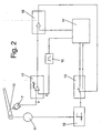
Figur 2- ein vereinfachtes, schematisches Blockschaltbild einer erfindungsgemäßen Ausstoßvorrichtung,
Figur 3- ein Diagramm zur Darstellung der Hebelgeschwindigkeit über die Zeit.
- FIG. 1
- a perspective view of a piece of furniture with an ejection device according to the invention,
- FIG. 2
- a simplified, schematic block diagram of an ejection device according to the invention,
- FIG. 3
- a diagram showing the lever speed over time.
In der nachfolgenden Figurenbezeichnung beziehen sich Begriffe wie oben, unten, links, rechts, vorne, hinten usw. ausschließlich auf die in den jeweiligen in den Figuren gewählte beispielhafte Darstellung und Position der Ausstoßvorrichtung, des Möbels und anderer Gegenstände. Diese Begriffe sind nicht einschränkend zu verstehen, das heißt in verschiedenen Arbeitsstellungen oder durch spiegelsymmetrische Auslegung oder dergleichen können sich diese Bezüge ändern.In the following figure designation, terms such as top, bottom, left, right, front, back, etc. refer exclusively to the exemplary representation and position of the ejection device, the furniture and other objects selected in the respective figures. These terms are not meant to be limiting, that is, in different working positions or by mirror-symmetrical design or the like, these references may change.
Wie in
In einer (nicht gezeigten) anderen Ausführungsform ist das bewegliche Möbelteil anstelle des Schubkastens als an dem Möbelkorpus 2 bewegliche Möbeltür ausgebildet.In a (not shown) another embodiment, the movable furniture part is formed instead of the drawer as movable on the
Benachbart zu einer Rückwand 5 des Schubkastens 3 ist eine erfindungsgemäße Ausstoßvorrichtung 6 mit einem Ausstoßelement vorgesehen. Das Ausstoßelement ist bevorzugt als Ausstoßhebel oder Auswurfstößel ausgebildet. Die Ausstoßvorrichtung 6 ist an einer vertikalen Leiste 9 gehalten, an der elektrische Leitungen zur Stromversorgung geführt sind.Adjacent to a
Das Öffnen des Schubkastens 3 wird von der elektromotorischen Ausstoßvorrichtung 6 unterstützt, die einen Ausstoßhebel 10 sowie eine Steuereinheit zur Steuerung des Elektromotors 11 aufweist.The opening of the
Mithilfe dieser Ausstoßvorrichtung 6 wird das an dem Möbelkorpus 2 beweglich gehaltene Möbelteil 3 im Normalbetrieb nach Berühren eines Bedienteils an der Frontseite des Möbelteils zumindest teilweise aus dem Möbelkorpus 2 durch den Ausstoßhebel 10 herausgestoßen, wobei der Ausstoßhebel 10 anschließend langsam durch den Elektromotor wieder in seine Ausgangsstellung zurückgefahren wird.By means of this ejection device 6, the
Die Ausstoßvorrichtung weist erfindungsgemäß des weiteren eine Geschwindigkeitsmesseinrichtung zur mittelbaren oder unmittelbaren Feststellung einer momentanen Einschubgeschwindigkeit des beweglichen Möbelteils 3 auf. Diese Geschwindigkeitsmesseinrichtung weist bevorzugt einen Positionssensor 7 und einen mit diesen direkt oder indirekt gekoppelten Zeitgeber 15 auf. Der Positionssensor ist bevorzugt so an dem Möbelkorpus 2 positioniert, dass er die Position des Ausstoßhebels 10 oder des beweglichen Möbelteils 3 erfasst In einer anderen Ausführungsform (nicht gezeigt) ist der Positionssensor so an einem Gehäuse der Ausstoßvorrichtung 6 angeordnet, dass er die Position des Ausstoßhebels 10 oder des beweglichen Möbelteils 3 erfasst.The ejection device according to the invention further comprises a speed measuring device for the direct or indirect determination of a current insertion speed of the
Der Positionssensor ist bevorzugt als berührungsloser Sensor, zum Beispiel als Infrarot-, Ultraschall- oder Funksensor ausgebildet. Bei der besonders bevorzugten Ausführungsform, bei der der Positionssensor an dem Gehäuse der Ausstoßvorrichtung 6 zur Erfassung der Position des Ausstoßhebels 10 angeordnet ist, ist der Positionssensor bevorzugt als kapazitiver Sensor ausgebildet.The position sensor is preferably designed as a non-contact sensor, for example as an infrared, ultrasonic or radio sensor. In the particularly preferred embodiment, in which the position sensor is arranged on the housing of the ejection device 6 for detecting the position of the
Durch die Geschwindigkeitsmesseinrichtung ist es möglich, dass bei einer plötzlichen Rückwärtsbewegung des beweglichen Möbelteils 3 in den Möbelkorpus 2 der Ausstoßhebel 10 rechtzeitig derart beschleunigt wird, dass er seine Ruheposition erreicht, bevor diesem ein Schaden durch das auf diesen eine Kraft ausübende Möbelteil droht.By the speed measuring device, it is possible that in a sudden backward movement of the
Anhand von
Der in dieser Figur gezeigten Situation geht voran, dass das Ausstoßelement 10 der Ausstoßvorrichtung 6 zunächst aus einer Ruhestellung in eine Betätigungsendstellung gebracht wurde, dabei das bewegliche Möbelteil 3 aus dem Möbelkorpus 2 herausgestoßen hat und sich nun in einer Rückwärtsbewegung von einer Betätigungsendstellung zurück in eine Ruhestellung befindet. Als alternative Ausgangssituation ist denkbar, dass das Ausstoßetement 10 sich noch auf dem Weg zu der Betätigungsendstellung befindet.The situation shown in this figure precedes that the
Der Ausstoßhebel 10 wird von dem Motor in einer Weise angetrieben, dass seine Rücklaufgeschwindigkeit deutlich geringer ist als die Vorlaufgeschwindigkeit beim Herausstoßen des Möbelteils 3. Dazu wird die Motordrehzahl über eine Motorsteuerschaltung entsprechend angesteuert. Während des Rücklaufs des Ausstoßhebels in seine Ruheposition wird die vom Ausstoßhebel 10 zurück gelegte Wegstrecke pro Zeiteinheit mit Hilfe des Sensors 7 und eines Zeitgebers 15 erfasst. In einer Geschwindigkeitsberechnungseinheit 17 wird daraus die aktuelle Geschwindigkeit des Ausstoßhebels 10 ermittelt. Die ermittelte Istgeschwindigkeit wird sodann mit einer vorbestimmten maximalen Rücklaufgeschwindigkeit verglichen. Stößt das bewegliche Möbelteil gegen den Austoβhebel 10, wird diese von diesem bewirkte externe Hebelbeschleunigung 16 erfasst. Liegt die daraus resultierende Istgeschwindigkeit über einer vorbestimmten Maximalgeschwindigkeit, löst eine Schaltschwelle ein Umschaltsignal zur Drehzahlumschaltung 13 in einer Ablaufsteuerung 14 für die Steuerung der Ausstoßhebelgeschwindigkeit aus. Das Umschaltsignal bewirkt, dass der Motor mit der maximalen Rücklaufgeschwindigkeit betrieben wird. Durch diese Maßnahme entzieht sich der Hebel durch Erhöhen der Geschwindigkeit einer Krafteinwirkung in Rücklaufrichtung. Hiermit wird der mechanische Impulsbelastung durch ein Stoß auf den Ausstoßhebel 10 entgegen gewirkt und dadurch ein Schaden von diesem abgewendetThe
In einer alternativen Ausführungsform, bei der der Positionssensor auf das bewegliche Möbelteil gerichtet ist, kann das Signal zur Drehzahlumschaltung zur Betreibung des Motors mit maximaler Rücklaufgeschwindigkeit bereits ausgesandt werden, bevor das sich zurückbewegende Möbelteil den Ausstoßhebel berührt.In an alternative embodiment, where the position sensor is directed toward the movable furniture part, the speed changeover signal for operating the motor at maximum return speed may already be sent out before the moving furniture part contacts the ejection lever.
Mit dem in
- 11
- MöbelFurniture
- 22
- Möbelkorpusfurniture body
- 33
- Schubkastendrawer
- 44
- Ausziehführungpull-out
- 55
- Rückwandrear wall
- 66
- Ausstoßvorrichtungejector
- 77
- Sensorsensor
- 88th
- Rückwandrear wall
- 99
- Leistestrip
- 1010
- Ausstoßelementejection element
- 1111
- Elektromotorelectric motor
- 1212
- Motorsteuerungmotor control
- 1313
- DrehzahlumschalterSpeed change
- 1414
- Ablaufsteuerungflow control
- 1515
- Zeitgebertimer
- 1616
- Erfassung der HebelbeschleunigungRecording the lever acceleration
- 1717
- Geschwindigkeitsberechnungspeed calculation
- aa
- Rücklaufgeschwindigkeit des Ausstoßhebels im NormalbetriebReturn speed of the ejection lever in normal operation
- bb
- Geschwindigkeitserhöhung aufgrund äußerer KrafteinwirkungSpeed increase due to external force
- cc
- Rücklaufgeschwindigkeit des Ausstoßhebels nach der Kollision mit dem beweglichen MöbelteilReturn speed of the ejection lever after collision with the movable furniture part
- dd
- Geschwindigkeitsabsenkung vor Erreichen der RuhepositionLowering the speed before reaching the rest position
- vs v s
- Schwellwert zur Detektierung der MaximalgeschwindigkeitThreshold for detecting the maximum speed
- tt
- ZeitTime
- vv
- Geschwindigkeitspeed
Claims (12)
- An ejection device (6) for a furniture part (3), which is mounted so it is movable on a furniture body (2), having an ejection element (10), an electric motor (11) driving the ejection element (10), and a control unit for controlling the electric motor (11), characterized in that the device (6) further has a velocity measuring unit for establishing an instantaneous return velocity of the ejection element (10), at which the ejection element (10) moves from an actuating position, which ejects the movable furniture part (3) out of the furniture body (2), in the direction of an idle position, which measuring unit is operationally linked to the control unit for the velocity-dependent actuation of the ejection element (10) in such a manner that upon exceeding a return target velocity of the ejection element (10), an acceleration of the ejection element (10) is activated at a maximum return velocity.
- The ejection device according to Claim 1, characterized in that the ejection element (10) is implemented as a lever or a tappet.
- The ejection device according to one of the preceding claims, characterized in that the movable furniture part (3) is implemented as a drawer (3) which is movable in the furniture body (2).
- The ejection device according to one of preceding Claims 1 to 3, characterized in that the movable furniture part (3) is implemented as a furniture door which is movable on the furniture body (2).
- The ejection device according to one of the preceding claims, characterized in that the velocity measuring unit has a position sensor (7) and a timer (15) coupled thereto.
- The ejection device according to Claim 5, characterized in that the position sensor (7) is situated on the furniture body (2) or a housing of the ejection device (6) in such a manner that it detects the position of the movable furniture part (3) or the ejection element (10).
- The ejection device according to Claim 6, characterized in that the position sensor (7) is implemented as a capacitive sensor or as a contactless sensor, in particular as an infrared, ultrasonic, or radio sensor.
- A piece of furniture having an ejection device (6) according to the preamble of Claim 1, the piece of furniture having a furniture body (2) and a movable furniture part (3), in particular a drawer (3), characterized by the features of the characterizing part of Claim 1.
- A method for actuating an ejection lever (10) of an ejection device (6) according to one of preceding Claims 1 to 7, an electric motor (11) driving the ejection element (10) and a control unit controlling the electric motor (11), characterized in that the method has the following method steps- measuring an instantaneous return velocity of the ejection element (10) or the movable furniture part (3),- establishing that a return target velocity has been exceeded, and- returning the ejection element (10) at elevated velocity, the method engaging in the controller of the electric motor (11) at a moment at which the movable furniture part (3) is already engaged with the ejection element (10) and pushing the ejection element (10) at a velocity which is greater than a specified return target velocity of the ejection element (10).
- The method according to Claim 9, characterized in that the method engages in the controller of the electric motor (11) at a moment at which the ejection element (10) is located in a reverse movement from an actuating end position back into an idle position and the movable furniture part (3) moves in the same direction as the ejection element (10).
- The method according to one of Claims 9 or 10, characterized in that the indirect measurement of an instantaneous velocity of the movable furniture part (3) is performed by a measurement of an instantaneous velocity of the ejection element (10), the ejection element (10) touching the movable furniture part (3) at least during the measurement.
- The method according to one of Claims 9 to 11, characterized in that the speed of the electric motor (11) is increased to increase the velocity of the ejection element (10).
Applications Claiming Priority (2)
| Application Number | Priority Date | Filing Date | Title |
|---|---|---|---|
| DE102008007377A DE102008007377A1 (en) | 2008-02-01 | 2008-02-01 | An ejection device and method for actuating an ejection lever |
| PCT/EP2009/050636 WO2009095342A1 (en) | 2008-02-01 | 2009-01-21 | Ejection device and method for actuating an ejection lever |
Publications (2)
| Publication Number | Publication Date |
|---|---|
| EP2240048A1 EP2240048A1 (en) | 2010-10-20 |
| EP2240048B1 true EP2240048B1 (en) | 2012-12-05 |
Family
ID=40513736
Family Applications (1)
| Application Number | Title | Priority Date | Filing Date |
|---|---|---|---|
| EP09705004A Active EP2240048B1 (en) | 2008-02-01 | 2009-01-21 | Ejection device and method for actuating an ejection lever |
Country Status (5)
| Country | Link |
|---|---|
| EP (1) | EP2240048B1 (en) |
| JP (1) | JP2011510718A (en) |
| DE (1) | DE102008007377A1 (en) |
| TW (1) | TW200944158A (en) |
| WO (1) | WO2009095342A1 (en) |
Families Citing this family (3)
| Publication number | Priority date | Publication date | Assignee | Title |
|---|---|---|---|---|
| DE102008030933A1 (en) * | 2008-07-02 | 2010-01-07 | Zimmer, Günther | Actuating device for pieces of furniture with at least one detachable shape memory element |
| DE202009001324U1 (en) * | 2009-02-04 | 2010-06-24 | Paul Hettich Gmbh & Co. Kg | Ejection unit and furniture |
| DE102010016608A1 (en) * | 2010-04-23 | 2011-10-27 | Paul Hettich Gmbh & Co. Kg | ejector |
Family Cites Families (9)
| Publication number | Priority date | Publication date | Assignee | Title |
|---|---|---|---|---|
| US5716114A (en) * | 1996-06-07 | 1998-02-10 | Pyxis Corporation | Jerk-resistant drawer operating system |
| AT500362B1 (en) * | 2002-06-27 | 2007-01-15 | Blum Gmbh Julius | ARRANGEMENT WITH A MOVABLE FURNITURE AND WITH A DRIVE UNIT |
| DE202004007168U1 (en) * | 2003-05-19 | 2004-08-26 | Julius Blum Ges.M.B.H. | Servo drive to open and close a furniture door or drawer is activated by manual pressure or tension on the drawer or door to operate between end stops |
| DE102004045568B4 (en) * | 2004-09-17 | 2016-11-03 | Grass Gmbh | Control and / or regulating device for an electric motor-operated adjusting device for adjusting, preferably for translational displacement, at least one furniture part |
| DE202006000535U1 (en) * | 2005-03-21 | 2006-03-09 | Julius Blum Gmbh | Furniture with furniture holder, for upper cabinets in e.g. kitchen has ejecting device and a pressurizable actuating device which pressurizes ejecting device to move a flap |
| DE202005006945U1 (en) * | 2005-04-28 | 2006-05-04 | Grass Gmbh | Opening and closing system, especially for furniture parts |
| AT501778B1 (en) | 2005-04-28 | 2009-11-15 | Blum Gmbh Julius | EJECTION DEVICE FOR A MOVABLE FURNITURE PART |
| AT503192B1 (en) * | 2006-02-15 | 2012-01-15 | Blum Gmbh Julius | FURNITURE WITH A GEARED FURNITURE |
| DE202006006189U1 (en) * | 2006-04-18 | 2007-08-30 | Paul Hettich Gmbh & Co. Kg | Drive device for movable furniture parts |
-
2008
- 2008-02-01 DE DE102008007377A patent/DE102008007377A1/en not_active Withdrawn
-
2009
- 2009-01-16 TW TW098101497A patent/TW200944158A/en unknown
- 2009-01-21 JP JP2010544666A patent/JP2011510718A/en active Pending
- 2009-01-21 WO PCT/EP2009/050636 patent/WO2009095342A1/en active Application Filing
- 2009-01-21 EP EP09705004A patent/EP2240048B1/en active Active
Also Published As
| Publication number | Publication date |
|---|---|
| EP2240048A1 (en) | 2010-10-20 |
| WO2009095342A1 (en) | 2009-08-06 |
| TW200944158A (en) | 2009-11-01 |
| JP2011510718A (en) | 2011-04-07 |
| DE102008007377A1 (en) | 2009-08-06 |
Similar Documents
| Publication | Publication Date | Title |
|---|---|---|
| AT502574B1 (en) | FURNITURE WITH A MOVABLE FURNITURE | |
| AT413472B (en) | EJECTION DEVICE FOR A MOVABLE FURNITURE PART | |
| AT503248B1 (en) | ARRANGEMENT WITH ELECTRIC DRIVE UNITS FOR DRAWERS | |
| EP1374732B1 (en) | Auxiliary pushing mechanism | |
| EP1994275B1 (en) | Device for switching on and switching off a vehicle engine as a function of the traffic situation | |
| EP1874158B1 (en) | Ejection device for a movable part of a piece of furniture | |
| AT510017B1 (en) | EJECTION DEVICE FOR A MOVABLE FURNITURE PART | |
| AT505209B1 (en) | DRIVE FOR A MOVABLE FURNITURE PART | |
| EP2373446B1 (en) | Method for operating a hammer | |
| AT511446B1 (en) | FURNITURE WITH REMOVABLE AND REMOVABLE INNER BASKET AND FLAP TO COVER THEM | |
| AT504509B1 (en) | Ejector for mobile furniture part has first ejector lever driven by electric motor, additional ejector lever mechanically coupled to it, movement detection sensor, drive unit activating control and/or regulating device | |
| DE202005019464U1 (en) | Adjustment device and electronic module | |
| EP2240048B1 (en) | Ejection device and method for actuating an ejection lever | |
| EP2139363B1 (en) | Piece of furniture and device for ejecting a furniture part which is movably received on a stationary furniture part | |
| WO2006069882A1 (en) | Built-in domestic appliance | |
| DE2461421A1 (en) | SAFETY GEAR SHIFTING ON A SNOW ROOM VEHICLE | |
| AT503192B1 (en) | FURNITURE WITH A GEARED FURNITURE | |
| EP1586731A2 (en) | Method for the control of an electrically operated window regulator for a vehicle | |
| EP2067418A1 (en) | Discharge device for a moveable piece of furniture and piece of furniture with such a device | |
| DE4432955C2 (en) | Method for operating an electromotive window regulator for a motor vehicle | |
| EP2268170B1 (en) | Method for controlling furniture drive units and a control apparatus | |
| EP3154397B1 (en) | Device for ejecting a furniture part and piece of furniture | |
| EP1989957B1 (en) | Electro motor-actuated extendable fitting for an extendable cupboard | |
| DE4214688C2 (en) | Setup for the automatic final shutdown of a mining plane | |
| EP3335565B1 (en) | Cloth type loader with auxiliary drive |
Legal Events
| Date | Code | Title | Description |
|---|---|---|---|
| PUAI | Public reference made under article 153(3) epc to a published international application that has entered the european phase |
Free format text: ORIGINAL CODE: 0009012 |
|
| 17P | Request for examination filed |
Effective date: 20100826 |
|
| AK | Designated contracting states |
Kind code of ref document: A1 Designated state(s): AT BE BG CH CY CZ DE DK EE ES FI FR GB GR HR HU IE IS IT LI LT LU LV MC MK MT NL NO PL PT RO SE SI SK TR |
|
| AX | Request for extension of the european patent |
Extension state: AL BA RS |
|
| DAX | Request for extension of the european patent (deleted) | ||
| 17Q | First examination report despatched |
Effective date: 20120207 |
|
| GRAP | Despatch of communication of intention to grant a patent |
Free format text: ORIGINAL CODE: EPIDOSNIGR1 |
|
| GRAS | Grant fee paid |
Free format text: ORIGINAL CODE: EPIDOSNIGR3 |
|
| GRAA | (expected) grant |
Free format text: ORIGINAL CODE: 0009210 |
|
| AK | Designated contracting states |
Kind code of ref document: B1 Designated state(s): AT BE BG CH CY CZ DE DK EE ES FI FR GB GR HR HU IE IS IT LI LT LU LV MC MK MT NL NO PL PT RO SE SI SK TR |
|
| REG | Reference to a national code |
Ref country code: GB Ref legal event code: FG4D Free format text: NOT ENGLISH |
|
| REG | Reference to a national code |
Ref country code: CH Ref legal event code: EP |
|
| REG | Reference to a national code |
Ref country code: AT Ref legal event code: REF Ref document number: 586799 Country of ref document: AT Kind code of ref document: T Effective date: 20121215 |
|
| REG | Reference to a national code |
Ref country code: IE Ref legal event code: FG4D Free format text: LANGUAGE OF EP DOCUMENT: GERMAN |
|
| REG | Reference to a national code |
Ref country code: DE Ref legal event code: R096 Ref document number: 502009005572 Country of ref document: DE Effective date: 20130131 |
|
| PG25 | Lapsed in a contracting state [announced via postgrant information from national office to epo] |
Ref country code: FI Free format text: LAPSE BECAUSE OF FAILURE TO SUBMIT A TRANSLATION OF THE DESCRIPTION OR TO PAY THE FEE WITHIN THE PRESCRIBED TIME-LIMIT Effective date: 20121205 Ref country code: SE Free format text: LAPSE BECAUSE OF FAILURE TO SUBMIT A TRANSLATION OF THE DESCRIPTION OR TO PAY THE FEE WITHIN THE PRESCRIBED TIME-LIMIT Effective date: 20121205 Ref country code: LT Free format text: LAPSE BECAUSE OF FAILURE TO SUBMIT A TRANSLATION OF THE DESCRIPTION OR TO PAY THE FEE WITHIN THE PRESCRIBED TIME-LIMIT Effective date: 20121205 Ref country code: ES Free format text: LAPSE BECAUSE OF FAILURE TO SUBMIT A TRANSLATION OF THE DESCRIPTION OR TO PAY THE FEE WITHIN THE PRESCRIBED TIME-LIMIT Effective date: 20130316 Ref country code: NO Free format text: LAPSE BECAUSE OF FAILURE TO SUBMIT A TRANSLATION OF THE DESCRIPTION OR TO PAY THE FEE WITHIN THE PRESCRIBED TIME-LIMIT Effective date: 20130305 |
|
| REG | Reference to a national code |
Ref country code: NL Ref legal event code: VDEP Effective date: 20121205 |
|
| REG | Reference to a national code |
Ref country code: LT Ref legal event code: MG4D |
|
| PG25 | Lapsed in a contracting state [announced via postgrant information from national office to epo] |
Ref country code: SI Free format text: LAPSE BECAUSE OF FAILURE TO SUBMIT A TRANSLATION OF THE DESCRIPTION OR TO PAY THE FEE WITHIN THE PRESCRIBED TIME-LIMIT Effective date: 20121205 Ref country code: GR Free format text: LAPSE BECAUSE OF FAILURE TO SUBMIT A TRANSLATION OF THE DESCRIPTION OR TO PAY THE FEE WITHIN THE PRESCRIBED TIME-LIMIT Effective date: 20130306 Ref country code: LV Free format text: LAPSE BECAUSE OF FAILURE TO SUBMIT A TRANSLATION OF THE DESCRIPTION OR TO PAY THE FEE WITHIN THE PRESCRIBED TIME-LIMIT Effective date: 20121205 Ref country code: PL Free format text: LAPSE BECAUSE OF FAILURE TO SUBMIT A TRANSLATION OF THE DESCRIPTION OR TO PAY THE FEE WITHIN THE PRESCRIBED TIME-LIMIT Effective date: 20121205 |
|
| BERE | Be: lapsed |
Owner name: PAUL HETTICH G.M.B.H. & CO. KG Effective date: 20130131 |
|
| PG25 | Lapsed in a contracting state [announced via postgrant information from national office to epo] |
Ref country code: IS Free format text: LAPSE BECAUSE OF FAILURE TO SUBMIT A TRANSLATION OF THE DESCRIPTION OR TO PAY THE FEE WITHIN THE PRESCRIBED TIME-LIMIT Effective date: 20130405 Ref country code: SK Free format text: LAPSE BECAUSE OF FAILURE TO SUBMIT A TRANSLATION OF THE DESCRIPTION OR TO PAY THE FEE WITHIN THE PRESCRIBED TIME-LIMIT Effective date: 20121205 Ref country code: BG Free format text: LAPSE BECAUSE OF FAILURE TO SUBMIT A TRANSLATION OF THE DESCRIPTION OR TO PAY THE FEE WITHIN THE PRESCRIBED TIME-LIMIT Effective date: 20130305 Ref country code: CZ Free format text: LAPSE BECAUSE OF FAILURE TO SUBMIT A TRANSLATION OF THE DESCRIPTION OR TO PAY THE FEE WITHIN THE PRESCRIBED TIME-LIMIT Effective date: 20121205 Ref country code: EE Free format text: LAPSE BECAUSE OF FAILURE TO SUBMIT A TRANSLATION OF THE DESCRIPTION OR TO PAY THE FEE WITHIN THE PRESCRIBED TIME-LIMIT Effective date: 20121205 |
|
| PG25 | Lapsed in a contracting state [announced via postgrant information from national office to epo] |
Ref country code: PT Free format text: LAPSE BECAUSE OF FAILURE TO SUBMIT A TRANSLATION OF THE DESCRIPTION OR TO PAY THE FEE WITHIN THE PRESCRIBED TIME-LIMIT Effective date: 20130405 Ref country code: MC Free format text: LAPSE BECAUSE OF NON-PAYMENT OF DUE FEES Effective date: 20130131 Ref country code: RO Free format text: LAPSE BECAUSE OF FAILURE TO SUBMIT A TRANSLATION OF THE DESCRIPTION OR TO PAY THE FEE WITHIN THE PRESCRIBED TIME-LIMIT Effective date: 20121205 Ref country code: NL Free format text: LAPSE BECAUSE OF FAILURE TO SUBMIT A TRANSLATION OF THE DESCRIPTION OR TO PAY THE FEE WITHIN THE PRESCRIBED TIME-LIMIT Effective date: 20121205 |
|
| REG | Reference to a national code |
Ref country code: CH Ref legal event code: PL |
|
| PLBE | No opposition filed within time limit |
Free format text: ORIGINAL CODE: 0009261 |
|
| STAA | Information on the status of an ep patent application or granted ep patent |
Free format text: STATUS: NO OPPOSITION FILED WITHIN TIME LIMIT |
|
| REG | Reference to a national code |
Ref country code: IE Ref legal event code: MM4A |
|
| REG | Reference to a national code |
Ref country code: FR Ref legal event code: ST Effective date: 20130930 |
|
| PG25 | Lapsed in a contracting state [announced via postgrant information from national office to epo] |
Ref country code: DK Free format text: LAPSE BECAUSE OF FAILURE TO SUBMIT A TRANSLATION OF THE DESCRIPTION OR TO PAY THE FEE WITHIN THE PRESCRIBED TIME-LIMIT Effective date: 20121205 Ref country code: LI Free format text: LAPSE BECAUSE OF NON-PAYMENT OF DUE FEES Effective date: 20130131 Ref country code: CH Free format text: LAPSE BECAUSE OF NON-PAYMENT OF DUE FEES Effective date: 20130131 Ref country code: BE Free format text: LAPSE BECAUSE OF NON-PAYMENT OF DUE FEES Effective date: 20130131 |
|
| 26N | No opposition filed |
Effective date: 20130906 |
|
| GBPC | Gb: european patent ceased through non-payment of renewal fee |
Effective date: 20130305 |
|
| PG25 | Lapsed in a contracting state [announced via postgrant information from national office to epo] |
Ref country code: HR Free format text: LAPSE BECAUSE OF FAILURE TO SUBMIT A TRANSLATION OF THE DESCRIPTION OR TO PAY THE FEE WITHIN THE PRESCRIBED TIME-LIMIT Effective date: 20121205 Ref country code: CY Free format text: LAPSE BECAUSE OF FAILURE TO SUBMIT A TRANSLATION OF THE DESCRIPTION OR TO PAY THE FEE WITHIN THE PRESCRIBED TIME-LIMIT Effective date: 20121205 Ref country code: FR Free format text: LAPSE BECAUSE OF NON-PAYMENT OF DUE FEES Effective date: 20130205 |
|
| PG25 | Lapsed in a contracting state [announced via postgrant information from national office to epo] |
Ref country code: IT Free format text: LAPSE BECAUSE OF FAILURE TO SUBMIT A TRANSLATION OF THE DESCRIPTION OR TO PAY THE FEE WITHIN THE PRESCRIBED TIME-LIMIT Effective date: 20121205 |
|
| REG | Reference to a national code |
Ref country code: DE Ref legal event code: R097 Ref document number: 502009005572 Country of ref document: DE Effective date: 20130906 |
|
| PG25 | Lapsed in a contracting state [announced via postgrant information from national office to epo] |
Ref country code: IE Free format text: LAPSE BECAUSE OF NON-PAYMENT OF DUE FEES Effective date: 20130121 Ref country code: GB Free format text: LAPSE BECAUSE OF NON-PAYMENT OF DUE FEES Effective date: 20130305 |
|
| PG25 | Lapsed in a contracting state [announced via postgrant information from national office to epo] |
Ref country code: MT Free format text: LAPSE BECAUSE OF FAILURE TO SUBMIT A TRANSLATION OF THE DESCRIPTION OR TO PAY THE FEE WITHIN THE PRESCRIBED TIME-LIMIT Effective date: 20121205 |
|
| PG25 | Lapsed in a contracting state [announced via postgrant information from national office to epo] |
Ref country code: TR Free format text: LAPSE BECAUSE OF FAILURE TO SUBMIT A TRANSLATION OF THE DESCRIPTION OR TO PAY THE FEE WITHIN THE PRESCRIBED TIME-LIMIT Effective date: 20121205 |
|
| PG25 | Lapsed in a contracting state [announced via postgrant information from national office to epo] |
Ref country code: MK Free format text: LAPSE BECAUSE OF FAILURE TO SUBMIT A TRANSLATION OF THE DESCRIPTION OR TO PAY THE FEE WITHIN THE PRESCRIBED TIME-LIMIT Effective date: 20121205 Ref country code: LU Free format text: LAPSE BECAUSE OF NON-PAYMENT OF DUE FEES Effective date: 20130121 Ref country code: HU Free format text: LAPSE BECAUSE OF FAILURE TO SUBMIT A TRANSLATION OF THE DESCRIPTION OR TO PAY THE FEE WITHIN THE PRESCRIBED TIME-LIMIT; INVALID AB INITIO Effective date: 20090121 |
|
| REG | Reference to a national code |
Ref country code: DE Ref legal event code: R079 Ref document number: 502009005572 Country of ref document: DE Free format text: PREVIOUS MAIN CLASS: A47B0088040000 Ipc: A47B0088400000 |
|
| REG | Reference to a national code |
Ref country code: DE Ref legal event code: R084 Ref document number: 502009005572 Country of ref document: DE |
|
| PGFP | Annual fee paid to national office [announced via postgrant information from national office to epo] |
Ref country code: AT Payment date: 20200121 Year of fee payment: 12 |
|
| REG | Reference to a national code |
Ref country code: AT Ref legal event code: MM01 Ref document number: 586799 Country of ref document: AT Kind code of ref document: T Effective date: 20210121 |
|
| PG25 | Lapsed in a contracting state [announced via postgrant information from national office to epo] |
Ref country code: AT Free format text: LAPSE BECAUSE OF NON-PAYMENT OF DUE FEES Effective date: 20210121 |
|
| P01 | Opt-out of the competence of the unified patent court (upc) registered |
Effective date: 20230410 |
|
| PGFP | Annual fee paid to national office [announced via postgrant information from national office to epo] |
Ref country code: DE Payment date: 20240119 Year of fee payment: 16 |