EP2239755A2 - Elektronenstrahlbeschleuniger - Google Patents
Elektronenstrahlbeschleuniger Download PDFInfo
- Publication number
- EP2239755A2 EP2239755A2 EP10169963A EP10169963A EP2239755A2 EP 2239755 A2 EP2239755 A2 EP 2239755A2 EP 10169963 A EP10169963 A EP 10169963A EP 10169963 A EP10169963 A EP 10169963A EP 2239755 A2 EP2239755 A2 EP 2239755A2
- Authority
- EP
- European Patent Office
- Prior art keywords
- accelerator
- exit window
- housing
- vacuum chamber
- electron
- Prior art date
- Legal status (The legal status is an assumption and is not a legal conclusion. Google has not performed a legal analysis and makes no representation as to the accuracy of the status listed.)
- Ceased
Links
Images




Classifications
-
- H—ELECTRICITY
- H01—ELECTRIC ELEMENTS
- H01J—ELECTRIC DISCHARGE TUBES OR DISCHARGE LAMPS
- H01J33/00—Discharge tubes with provision for emergence of electrons or ions from the vessel; Lenard tubes
-
- H—ELECTRICITY
- H01—ELECTRIC ELEMENTS
- H01J—ELECTRIC DISCHARGE TUBES OR DISCHARGE LAMPS
- H01J5/00—Details relating to vessels or to leading-in conductors common to two or more basic types of discharge tubes or lamps
- H01J5/02—Vessels; Containers; Shields associated therewith; Vacuum locks
- H01J5/06—Vessels or containers specially adapted for operation at high tension, e.g. by improved potential distribution over surface of vessel
-
- B—PERFORMING OPERATIONS; TRANSPORTING
- B65—CONVEYING; PACKING; STORING; HANDLING THIN OR FILAMENTARY MATERIAL
- B65B—MACHINES, APPARATUS OR DEVICES FOR, OR METHODS OF, PACKAGING ARTICLES OR MATERIALS; UNPACKING
- B65B55/00—Preserving, protecting or purifying packages or package contents in association with packaging
- B65B55/02—Sterilising, e.g. of complete packages
-
- B—PERFORMING OPERATIONS; TRANSPORTING
- B65—CONVEYING; PACKING; STORING; HANDLING THIN OR FILAMENTARY MATERIAL
- B65B—MACHINES, APPARATUS OR DEVICES FOR, OR METHODS OF, PACKAGING ARTICLES OR MATERIALS; UNPACKING
- B65B55/00—Preserving, protecting or purifying packages or package contents in association with packaging
- B65B55/02—Sterilising, e.g. of complete packages
- B65B55/04—Sterilising wrappers or receptacles prior to, or during, packaging
- B65B55/10—Sterilising wrappers or receptacles prior to, or during, packaging by liquids or gases
- B65B55/103—Sterilising flat or tubular webs
Definitions
- Conventional electron beam machines employed for industrial purposes include an electron beam accelerator which directs an electron beam onto the material to be processed.
- the accelerator has a large lead encased vacuum chamber containing an electron generating filament or filaments powered by a filament power supply. During operation, the vacuum chamber is continuously evacuated by vacuum pumps.
- the filaments are surrounded by a housing having a grid of openings which face a metallic foil electron beam exit window positioned on one side of the vacuum chamber.
- a high voltage potential is imposed between the filament housing and the exit window with a high voltage power supply. Electrons generated by the filaments accelerate from the filaments in an electron beam through the grid of openings in the housing and out through the exit window.
- An extractor power supply is typically included for flattening electric field lines in the region between the filaments and the exit window. This prevents the electrons in the electron beam from concentrating in the center of the beam as depicted in graph 1 of FIG. 1 , and instead, evenly disperses the electrons across the width of the beam as depicted in graph 2 of FIG. 1 .
- the present invention provides a compact, less complex electron accelerator for an electron beam machine which allows the electron beam machine to be more easily maintained and does not require maintenance by personnel highly trained in vacuum technology and accelerator technology.
- an electron accelerator comprising:
- a preferred embodiment of the present invention is directed to an electron accelerator including a vacuum chamber having an electron beam exit window.
- the exit window is formed of metallic foil bonded in metal to metal contact with the vacuum chamber to provide a gas tight seal therebetween .
- the exit window is less than about 12.5 microns thick.
- the vacuum chamber is hermetically sealed to preserve a permanent self sustained vacuum therein.
- An electron generator is positioned within the vacuum chamber for generating electrons.
- a housing surrounds the electron generator. The housing has an electron permeable region formed in the housing between the electron generator and the exit window for allowing electrons to accelerate from the electron generator out the exit window in an electron beam when a voltage potential is applied between the housing and the exit window.
- a series of openings in the housing forms the electron permeable region.
- the exit window is preferably formed of titanium foil between about 8 to 10 microns thick and is supported by a support plate having a series of holes therethrough which allow the electrons to pass through.
- the configuration of the holes in the support plate are arrangable to vary electron permeability across the support plate for providing the electron beam with a desired variable intensity profile.
- the exit window has an outer edge which is either brazed, welded or bonded to the vacuum chamber to provide a gas tight seal therebetween.
- the vacuum chamber preferably includes an elongate ceramic member.
- the elongate ceramic member is corrugated which allows higher voltages to be used.
- An annular spring member is coupled between the exit window and the corrugated ceramic member to compensate for different rates of expansion.
- the elongate ceramic member has a smooth surface and a metallic shell surrounds the ceramic member.
- the ceramic member includes a frustoconical hole which allows an electrical lead to extend through the frustoconical hole for supplying power to the electron generator.
- a flexible insulating plug surrounds the electrical lead and includes a frustoconical surface for sealing with the frustoconical hole.
- a retaining cap is secured to the shell for retaining the plug within the frustoconical hole.
- the present invention also provides an electron accelerator including a vacuum chamber having an electron beam exit window.
- An electron generator is positioned within the vacuum chamber for generating electrons.
- a housing surrounds the electron generator and has an electron permeable region formed in the housing between the electron generator and the exit window for allowing electrons to accelerate from the electron generator out the exit window in an electron beam when a voltage potential is applied between the housing and the exit window.
- the housing also has a passive electrical field line shaper for causing electrons to be uniformly distributed across the electron beam by flattening electrical field lines between the electron generator and the exit window.
- the electron permeable region includes a first series of openings in the housing between the electron generator and the exit window while the passive electrical field line shaper includes a second and third series of openings formed in the housing on opposite sides of the electron generator.
- electron beam accelerator 10 is a replaceable modular accelerator which is installed in an electron beam machine housing (not shown).
- Accelerator 10 includes an elongate generally cylindrical two piece outer shell 14 which is sealed at both ends. The proximal end of outer shell 14 is enclosed by a proximal end cap 16 which is welded to outer shell 14.
- Outer shell 14 and end cap 16 are each preferably made from stainless steel but alternatively can be made of other suitable metals.
- an electron beam exit window membrane 24 made of titanium foil which is brazed along edge 23 to a stainless steel distal end cap 20.
- End cap 20 is welded to outer shell 14.
- Exit window 24 is typically between about 6 to 12 microns thick with about 8 to 10 microns being the more preferred range.
- exit window 24 can be made of other suitable metallic foils such as magnesium, aluminum, beryllium or suitable non-metallic low density materials such as ceramics.
- exit window 24 can be welded or bonded to end cap 20.
- a rectangular support plate 22 having holes or openings 22a for the passage of electrons therethrough is bolted to end cap 20 with bolts 22b and helps support exit window 24.
- Support plate 22 is preferably made of copper for dissipating heat but alternatively can be made of other suitable metals such as stainless steel, aluminum or titanium.
- the holes 22a within support plate 22 are about 1/8 inch in diameter and provide about an 80% opening for electrons to pass through exit window 24.
- End cap 20 includes a cooling passage 27 through which cooling fluid is pumped for cooling the end cap 20, support plate 22 and exit window 24.
- the cooling fluid enters inlet port 25a and exits outlet port 25b.
- the inlet 25a and outlet 25b ports mate with coolant supply and return ports on the electron beam machine housing.
- the coolant supply and return ports include "0" ring seals for sealing to the inlet 25a and outlet 25b ports.
- Accelerator 10 is about 12 inches in diameter by 20 inches long and about 50 pounds in weight.
- a high voltage electrical connecting receptacle 18 for accepting the connector 12 of a high voltage power cable is mounted to end cap 16.
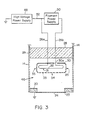
- the high voltage cable supplies accelerator 10 with power from a high voltage power supply 48 and a filament power supply 50.
- High voltage power supply 48 preferably provides about 100 kv but alternatively can be higher or lower depending upon the thickness of exit window 24.
- Filament power supply 50 preferably provides about 15 volts.
- Two electrical leads 26a/26b extend downwardly from receptacle 18 through a disk-shaped high voltage ceramic insulator 28 which divides accelerator 10 into an upper insulating chamber 44 and a lower vacuum chamber 46.
- An electron generator 31 is positioned within vacuum chamber 46 and preferably consists of three 8 inch long filaments 32 ( FIG. 4 ) made of tungsten which are electrically connected together in parallel. Alternatively, two filaments 32 can be employed.
- the electron generator 31 is surrounded by a stainless steel filament housing 30.
- Filament housing 30 has a series of grid like openings 34 along a planar bottom 33 and a series of openings 35 along the four sides of housing 30.
- the filaments are preferably positioned within housing 30 about midway between bottom 33 and the top of housing 30. Openings 35 do not extend substantially above filaments 32.
- Electrical lead 26a and line 52 electrically connect filament housing 30 to high voltage power supply 48.
- Electrical lead 26b passes through a hole 30a in filament housing 30 to electrically connect filaments 32 to filament power supply 50.
- the exit window 24 is electrically grounded to impose a high voltage potential between filament housing 30 and exit window 24.
- An inlet 39 is provided on vacuum chamber 46 for evacuating vacuum chamber 46.
- Inlet 39 includes a stainless steel outer pipe 36 which is welded to outer shell 14 and a sealable copper tube 38 which is brazed to pipe 36. Once vacuum chamber 46 is evacuated, pipe 38 is cold welded under pressure to form a seal 40 for hermetically sealing vacuum chamber 46.
- accelerator 10 is mounted to an electron beam machine, and electrically connected to connector 12.
- the housing of the electron beam machine includes a lead enclosure which surrounds accelerator 10.
- Filaments 32 are heated up to about 4200°F by electrical power from filament power supply 50 (AC or DC) which causes free electrons to form on filaments 32.
- filament power supply 50 AC or DC
- the high voltage potential between the filament housing 30 and exit window 24 imposed by high voltage power supply 48 causes the free electrons 56 on filaments 32 to accelerate from the filaments 32 in an electron beam 58 out through openings 34 in housing 30 and the exit window 24 ( FIG. 4 ).
- the side openings 35 create small electric fields around the openings 35 which flatten the high voltage electric field lines 54 between the filaments 32 and the exit window 24 relative to the plane of the bottom 33 of housing 30.
- By flattening electric field lines 54 electrons 56 of electron beam 58 exit housing 30 through openings 34 in a relatively straight manner rather than focusing towards a central location as depicted by graph 1 of FIG. 1 .
- the narrower higher density electron beam of graph 1 of FIG. 1 is undesirable because it will burn a hole through exit window 24.
- FIG. 5 depicts housing 30 with side openings 35 omitted.
- electric field lines 54 arch upwardly. Since electrons 56 travel about perpendicularly to the electric field lines 54, the electrons 56 are focused in a narrow electron beam 57. In contrast, as seen in FIG. 4 , the electric field lines 54 are flat allowing the electrons 56 to travel in a wider substantially non-focusing electron beam 58. Accordingly, while conventional accelerators need to employ an extractor power supply at high voltage to flatten the high voltage electric field lines for evenly dispersing the electrons across the electric beam, the present invention is able to accomplish the same results in a simple and inexpensive manner by means of the openings 35.
- accelerator 10 When the filaments 32 or exit window 24 need to be replaced, the entire accelerator 10 is simply disconnected from the electron beam machine housing and replaced with a new accelerator 10.
- the new accelerator 10 is already preconditioned for high voltage operation and, therefore, the down time of the electron beam machine is merely minutes. Since only one part needs to be replaced, the operator of the electron beam machine does not need to be highly trained in vacuum technology and accelerator technology maintenance. In addition, accelerator 10 is small enough and light enough in weight to be replaced by one person.
- the old accelerator is preferably sent to another location such as a company specializing in vacuum technology.
- the vacuum chamber 46 is opened by removing the exit window 24 and support plate 22.
- housing 30 is removed from vacuum chamber 46 and the filaments 32 are replaced. If needed, the insulating medium within upper chamber 44 is removed through valve 42. The housing 30 is then remounted back in vacuum chamber 46.
- Support plate 22 is bolted to end cap 20 and exit window 24 is replaced.
- the edge 23 of the new exit window 24 is brazed to end cap 20 to form a gas tight seal therebetween. Since exit window 24 covers the support plate 22, bolts 22b and bolt holes, it serves the secondary function of sealing over the support plate 22 without any leaks, "O"-rings or the like.
- Copper tube 38 is removed and a new copper tube 38 is brazed to pipe 36.
- the exit window 24 can be easily made 8 to 10 microns thick or even as low as 6 microns thick. The reason for this is that dust or other contaminants are prevented from accumulating on exit window 24 between the exit window 24 and the support plate 22. Such contaminants will poke holes through an exit window 24 having a thickness under 12.5 microns.
- electron beam exit windows in conventional accelerators must be 12.5 to 15 microns thick because they are assembled at the site in dusty conditions during maintenance. An exit window 12.5 to 15 microns thick is thick enough to prevent dust from perforating the exit window. Since the present invention exit window 24 is typically thinner than exit windows on conventional accelerators, the power required for accelerating electrons through the exit window 24 is considerably less.
- accelerator 10 is more efficient than conventional accelerators.
- the lower voltage also allows the accelerator 10 to be more compact in size and allows a disk-shaped insulator 28 to be used which is smaller than the cylindrical or conical insulators employed in conventional accelerators.
- the reason accelerator 10 can be more compact then conventional accelerators is that the components of accelerator 10 can be closer together due to the lower voltage.
- the controlled clean environment within vacuum chamber 46 allows the components to be even closer together.
- Conventional accelerators operate at higher voltages and have more contaminants within the accelerator which requires greater distances between components to prevent electrical arcing therebetween. In fact, contaminants from the vacuum pumps in conventional accelerators migrate into the accelerator during use.
- the vacuum chamber 46 is then evacuated through inlet 39 and tube 38 is hermetically sealed by cold welding. Once vacuum chamber 46 is sealed, vacuum chamber 46 remains under a permanent vacuum without requiring the use of an active vacuum pump. This reduces the complexity and cost of operating the present invention accelerator 10.
- the accelerator 10 is then preconditioned for high voltage operation by connecting the accelerator 10 to an electron beam machine and gradually increasing the voltage to burn off any contaminants within vacuum chamber 46 and on exit window 24. Any molecules remaining within the vacuum chamber 46 are ionized by the high voltage and/or electron beam and are accelerated towards housing 30. The ionized molecules collide with housing 30 and become trapped on the surfaces of housing 30, thereby further improving the vacuum.
- the vacuum chamber 46 can also be evacuated while the accelerator 10 is preconditioned for high voltage operation. The accelerator 10 is disconnected from the electron beam machine and stored for later use.
- FIG. 6 depicts a system 64 including three accelerators 10a, 10b and 10c which are staggered relative to each other to radiate the entire width of a moving product 62 with electron beams 60. Since the electron beam 60 of each accelerator 10a, 10b, 10c is narrower than the outer diameter of an accelerator, the accelerators cannot be positioned side-by-side. Instead, accelerator 10b is staggered slightly to the side and backwards relative to accelerators 10a and 10c along the line of movement of the product 62 such that the ends of each electron beam 60 will line up with each other in the lateral direction. As a result, the moving product 62 can be accumulatively radiated by the electron beams 60 in a step-like configuration as shown. Although three accelerators have been shown, alternatively, more than three accelerators 10 can be staggered to radiate wider products or only two accelerators 10 can be staggered to radiate narrower products.
- FIGs. 7 and 8 depict another preferred method of electrically connecting leads 26a and 26b to filament housing 30 and filaments 32.
- Lead 26a is fixed to the top of filament housing 30.
- Three filament brackets 102 extend downwardly from the top of filament housing 30.
- a filament mount 104 is mounted to each bracket 102.
- An insulation block 110 and a filament mount 108 are mounted to the opposite side of filament housing 30.
- the filaments 32 are mounted to and extend between filament mounts 104 and 108.
- a flexible lead 106 electrically connects lead 26b to filament mount 108.
- Filament brackets 102 have a spring-like action which compensate for the expansion and contraction of filaments 32 during use.
- a cylindrical bracket 112 supports housing 30 instead of leads 26a/26b.
- filament arrangement 90 is another preferred method of electrically connecting multiple filaments together in order to increase the width of the electron beam over that provided by a single filament.
- Filaments 92 are positioned side-by-side and electrically connected in series to each other by electrical leads 94.
- filament arrangement 98 depicts a series of filaments 97 which are positioned side-by-side and electrically connected together in parallel by two electrical leads 96. Filament arrangement 98 is also employed to increase the width of the electron beam.
- Accelerator 70 is suitable for radiating wide areas with an electron beam without employing multiple staggered accelerators and is suitable for use in narrow environments. Accelerator 70 can be made up to about 3 to 4 feet long and can be staggered to provide even wider coverage.
- accelerator 100 is yet another preferred embodiment of the present invention.
- Accelerator 100 includes a generally cylindrical outer shell 102 formed of ceramic material having a vacuum chamber 104 therein.
- Outer shell 102 has a closed proximal end 106 and an open distal end 118 opposite thereof.
- the external surface of outer shell 102 includes a series of corrugations 102a which allows accelerator 100 to run at higher voltages than if outer shell 102 were smooth.
- the open end 118 has a region with a smooth outer surface.
- a metallic end cap 110 surrounds and covers the smooth open distal end 118 of outer shell 102 to enclose vacuum chamber 104.
- End cap 110 is brazed to an intermediate annular metallic spring 108 which in turn is brazed to outer shell 102, thereby sealing vacuum chamber 104.
- Spring 108 allows the ceramic outer shell 102 and end cap 110 to expand and contract at different rates in radial as well axial directions while maintaining a gas tight seal therebetween. Spring 108 accomplishes this by spacing the end cap 110 slightly apart from outer shell 102 as well as being formed of resilient material.
- Spring 108 includes an annular inner V-shaped ridge 108a, the inner leg thereof brazed to outer shell 102.
- An annular outer flange 108b extends radially outward from the V-shaped ridge 108a and is brazed to end cap 110.
- accelerator 130 is still another preferred accelerator.
- Accelerator 130 includes a metallic outer shell 122 surrounding a ceramic inner shell 124 having a smooth external surface.
- the open end 118 of inner shell 124 preferably extends to support plate 22 thereby forming an annular wall 136 of ceramic material between the vacuum chamber 134 and outer shell 122.
- distal end 118 can terminate before reaching support plate 22.
- Inner shell 124 has a frustoconical opening 124a extending through proximal end 119 opposite to distal end 118.
- An electrical lead 128 having a connector 138 extends through frustoconical hole 124a for providing power to filament housing 30 and electron generator 31 via electrical leads 26a/26b.
- Filament housing 30 and electron generator 31 are similar to that in accelerator 100 ( FIG. 12 ).
- Electrical lead 128 also extends through the central opening 126a of a flexible polymeric insulating plug 126.
- Insulating plug 126 includes a mating frustoconical outer surface 126b for sealing with the frustoconical hole 124a.
- a retaining cap 140 secured to outer shell 122 exerts a compressive axial force on plug 126 which compresses plug 126 against the converging surfaces of frustoconical hole 124a and squeezes plug 126 around electrical lead 128 for sealing between electrical lead 128 and inner shell 124.
- plug 126 is made of ethylene propylene rubber with an electrical resistance of 10 14 to 10 15 ohms-cm.
- inner shell 124 preferably has an electrical resistance of 10 14 ohms-cm.
- FIG. 14 depicts a preferred filament 32 for the electron generator 31 employed in accelerators 100 and 130 ( FIGs. 12 and 13 ).
- Filament 32 is formed with a series of curves into a generally W shape. This allows filament 32 to expand and contract during operation without requiring the support of resilient or spring-loaded components.
- the ends of filament 32 can be bent in a hair pin turn as shown in FIG. 14 for insertion through openings or slots within electrical leads 26a and 26b. If desired, more than one filament 32 can be employed.
- the holes 22a of support plate 22 within accelerators 100 and 130 can have a pattern of holes 142 that is filled or plugged such that the resultant electron beam emitted has a variable intensity profile across the beam.
- the holes 22a can be arranged within support plate 22 during manufacture to produce the desired pattern. Although a particular pattern 142 has been depicted, any desirable pattern can be formed.
- an extension nozzle 144 can be secured to accelerators 100 and 130 ( FIGs. 12 and 13 ). In such a situation, the exit window 24 would be positioned at the far end of nozzle 144. Nozzle 144 allows insertion within narrow openings such as cups and bottles for sterilization therein.
- the series of openings 35 in the filament housings form a passive electrical field line shaper for shaping electrical field lines, in particular, a flattener for flattening electrical field lines.
- the term "passive" meaning that the electrical field lines are shaped without a separate extractor power supply.
- electrical field lines can be shaped by employing multiple filaments.
- partitions or passive electrodes can be positioned between the filaments for further shaping electrical field lines. Multiple filaments, partitions or passive electrodes can be employed as flatteners for flattening electrical field lines as well as other shapes.
- the thickness of a titanium exit window is preferably under 12.5 microns (between 6 and 12 microns), the thickness of the exit window can be greater than 12.5 microns for certain applications if desired.
- high voltage power supply 49 should provide about 100 kv to 150 kv.
- the thickness of the exit window can be made thicker than a corresponding titanium exit window while achieving the same electron beam characteristics.
- the accelerators are preferably cylindrical in shape but can have other suitable shapes such as rectangular or oval cross sections. Once the present invention accelerator is made in large quantities to be made inexpensively, it can be used as a disposable unit. Receptacle 18 of accelerators 10 and 70 can be positioned perpendicular to longitudinal axis A for space constraint reasons.
Landscapes
- Particle Accelerators (AREA)
- Physical Or Chemical Processes And Apparatus (AREA)
- Acyclic And Carbocyclic Compounds In Medicinal Compositions (AREA)
- Luminescent Compositions (AREA)
- Electron Sources, Ion Sources (AREA)
- Apparatus For Disinfection Or Sterilisation (AREA)
- Lasers (AREA)
Applications Claiming Priority (2)
| Application Number | Priority Date | Filing Date | Title |
|---|---|---|---|
| US09/349,592 US6407492B1 (en) | 1997-01-02 | 1999-07-09 | Electron beam accelerator |
| EP00943252A EP1194944B1 (de) | 1999-07-09 | 2000-06-28 | Elektronenstrahlbeschleuniger |
Related Parent Applications (2)
| Application Number | Title | Priority Date | Filing Date |
|---|---|---|---|
| EP00943252A Division EP1194944B1 (de) | 1999-07-09 | 2000-06-28 | Elektronenstrahlbeschleuniger |
| EP00943252.7 Division | 2000-06-28 |
Publications (2)
| Publication Number | Publication Date |
|---|---|
| EP2239755A2 true EP2239755A2 (de) | 2010-10-13 |
| EP2239755A3 EP2239755A3 (de) | 2015-11-25 |
Family
ID=23373097
Family Applications (2)
| Application Number | Title | Priority Date | Filing Date |
|---|---|---|---|
| EP00943252A Expired - Lifetime EP1194944B1 (de) | 1999-07-09 | 2000-06-28 | Elektronenstrahlbeschleuniger |
| EP10169963.5A Ceased EP2239755A3 (de) | 1999-07-09 | 2000-06-28 | Elektronstrahlbeschleuniger |
Family Applications Before (1)
| Application Number | Title | Priority Date | Filing Date |
|---|---|---|---|
| EP00943252A Expired - Lifetime EP1194944B1 (de) | 1999-07-09 | 2000-06-28 | Elektronenstrahlbeschleuniger |
Country Status (8)
| Country | Link |
|---|---|
| EP (2) | EP1194944B1 (de) |
| JP (1) | JP4808879B2 (de) |
| CN (1) | CN1369105A (de) |
| AT (1) | ATE496387T1 (de) |
| AU (1) | AU5774800A (de) |
| BR (1) | BR0013191A (de) |
| DE (1) | DE60045551D1 (de) |
| WO (1) | WO2001004924A1 (de) |
Families Citing this family (18)
| Publication number | Priority date | Publication date | Assignee | Title |
|---|---|---|---|---|
| US6630774B2 (en) | 2001-03-21 | 2003-10-07 | Advanced Electron Beams, Inc. | Electron beam emitter |
| EP1991993B2 (de) | 2006-02-14 | 2017-01-25 | Hitachi Zosen Corporation | Elektronenstrahlemitter |
| JP2011521259A (ja) | 2008-05-21 | 2011-07-21 | アドバンスト・エレクトロン・ビームズ・インコーポレーテッド | スロットを含む電子銃を備える電子ビーム照射装置 |
| DE102008045187A1 (de) | 2008-08-30 | 2010-03-04 | Krones Ag | Elektronenstrahlsterilisation für Behältnisse |
| SE0802102A2 (sv) | 2008-10-07 | 2010-07-20 | Tetra Laval Holdings & Finance | Styrmetod för en anordning för elektronstrålesterilisering och en anordning för utförande av nämnda metod |
| US20110012030A1 (en) * | 2009-04-30 | 2011-01-20 | Michael Lawrence Bufano | Ebeam sterilization apparatus |
| US8293173B2 (en) | 2009-04-30 | 2012-10-23 | Hitachi Zosen Corporation | Electron beam sterilization apparatus |
| CN102074431B (zh) * | 2010-11-30 | 2012-07-04 | 南京大学 | 一种电子直线加速器用的电子枪控制电路 |
| JP5911507B2 (ja) * | 2010-12-16 | 2016-04-27 | 日立造船株式会社 | プラズマまたはオゾンの生成システム、及びプラズマまたはオゾンの生成方法 |
| JP5910290B2 (ja) * | 2012-04-26 | 2016-04-27 | Jfeエンジニアリング株式会社 | 粒子線透過窓の製造方法 |
| CN104616949B (zh) * | 2013-11-05 | 2017-10-27 | 上海联影医疗科技有限公司 | 一种电子输出窗 |
| JP6628728B2 (ja) * | 2014-02-19 | 2020-01-15 | 日立造船株式会社 | 電子線照射装置、および照射検出を有する照射システム |
| BR112016021845B1 (pt) * | 2014-03-24 | 2020-11-17 | Tetra Laval Holdings & Finance Sa | emissor de feixe de elétron, e, dispositivo de esterilização |
| JP6119898B2 (ja) * | 2016-03-29 | 2017-04-26 | Jfeエンジニアリング株式会社 | 粒子線透過窓 |
| WO2018137042A1 (en) * | 2017-01-26 | 2018-08-02 | Canadian Light Source Inc. | Exit window for electron beam in isotope production |
| CN106601577A (zh) * | 2017-02-28 | 2017-04-26 | 公安部第研究所 | 波纹玻壳x射线管 |
| CN111010794A (zh) * | 2019-12-26 | 2020-04-14 | 北京机电工程研究所 | 一种等离子体产生单元及使用方法 |
| JP2021189038A (ja) * | 2020-05-29 | 2021-12-13 | 浜松ホトニクス株式会社 | 電子線照射装置及び電子線照射装置の製造方法 |
Citations (6)
| Publication number | Priority date | Publication date | Assignee | Title |
|---|---|---|---|---|
| JPS5693949U (de) * | 1979-12-19 | 1981-07-25 | ||
| US5414267A (en) * | 1993-05-26 | 1995-05-09 | American International Technologies, Inc. | Electron beam array for surface treatment |
| EP0668390A2 (de) * | 1994-02-18 | 1995-08-23 | Kimberly-Clark Corporation | Verfahren zur verbesserten chemischen Bindung mittels Elektronenstrahlen |
| US5483074A (en) * | 1995-01-11 | 1996-01-09 | Litton Systems, Inc. | Flood beam electron gun |
| WO1997007024A1 (en) * | 1995-08-11 | 1997-02-27 | Tetra Laval Holdings & Finance S.A. | Method for sterilizing flowable product packages |
| WO1998029895A1 (en) * | 1997-01-02 | 1998-07-09 | Applied Advanced Technologies, Inc. | Electron beam accelerator |
Family Cites Families (8)
| Publication number | Priority date | Publication date | Assignee | Title |
|---|---|---|---|---|
| JPS5362977A (en) * | 1976-11-17 | 1978-06-05 | Hitachi Ltd | Plane face pressure insulated electron gun |
| JPS5366151A (en) * | 1976-11-26 | 1978-06-13 | Hitachi Ltd | Electron gun unit of electron microscope and equivalent unit |
| JPS5568057A (en) * | 1978-11-17 | 1980-05-22 | Hitachi Ltd | Electron gun |
| DE3333686A1 (de) * | 1983-09-17 | 1985-04-04 | Leybold-Heraeus GmbH, 5000 Köln | Elektronenstrahlkanone zum erwaermen von materialien, insbesondere zum schweissen |
| DE8817060U1 (de) * | 1988-10-13 | 1992-04-23 | Bösch, Hubert, Lustenau | Dichtung für Ventile oder Flansche, insbesondere für die Vakuumtechnik |
| GB9220226D0 (en) * | 1992-09-24 | 1992-11-04 | Eev Ltd | Electron gun assemblies |
| JPH10232290A (ja) * | 1997-02-20 | 1998-09-02 | Japan Atom Energy Res Inst | セラミックスベローズの製造方法 |
| JPH1130700A (ja) * | 1997-05-15 | 1999-02-02 | Toyo Ink Mfg Co Ltd | パターン形成方法およびパターン形成物 |
-
2000
- 2000-06-28 CN CN00811336A patent/CN1369105A/zh active Pending
- 2000-06-28 DE DE60045551T patent/DE60045551D1/de not_active Expired - Lifetime
- 2000-06-28 EP EP00943252A patent/EP1194944B1/de not_active Expired - Lifetime
- 2000-06-28 AT AT00943252T patent/ATE496387T1/de active
- 2000-06-28 BR BR0013191-1A patent/BR0013191A/pt active Search and Examination
- 2000-06-28 JP JP2001509058A patent/JP4808879B2/ja not_active Expired - Lifetime
- 2000-06-28 WO PCT/US2000/017816 patent/WO2001004924A1/en not_active Ceased
- 2000-06-28 AU AU57748/00A patent/AU5774800A/en not_active Abandoned
- 2000-06-28 EP EP10169963.5A patent/EP2239755A3/de not_active Ceased
Patent Citations (6)
| Publication number | Priority date | Publication date | Assignee | Title |
|---|---|---|---|---|
| JPS5693949U (de) * | 1979-12-19 | 1981-07-25 | ||
| US5414267A (en) * | 1993-05-26 | 1995-05-09 | American International Technologies, Inc. | Electron beam array for surface treatment |
| EP0668390A2 (de) * | 1994-02-18 | 1995-08-23 | Kimberly-Clark Corporation | Verfahren zur verbesserten chemischen Bindung mittels Elektronenstrahlen |
| US5483074A (en) * | 1995-01-11 | 1996-01-09 | Litton Systems, Inc. | Flood beam electron gun |
| WO1997007024A1 (en) * | 1995-08-11 | 1997-02-27 | Tetra Laval Holdings & Finance S.A. | Method for sterilizing flowable product packages |
| WO1998029895A1 (en) * | 1997-01-02 | 1998-07-09 | Applied Advanced Technologies, Inc. | Electron beam accelerator |
Also Published As
| Publication number | Publication date |
|---|---|
| CN1369105A (zh) | 2002-09-11 |
| BR0013191A (pt) | 2002-04-30 |
| JP4808879B2 (ja) | 2011-11-02 |
| WO2001004924A1 (en) | 2001-01-18 |
| ATE496387T1 (de) | 2011-02-15 |
| EP1194944A1 (de) | 2002-04-10 |
| EP2239755A3 (de) | 2015-11-25 |
| DE60045551D1 (de) | 2011-03-03 |
| EP1194944B1 (de) | 2011-01-19 |
| JP2003504605A (ja) | 2003-02-04 |
| AU5774800A (en) | 2001-01-30 |
Similar Documents
| Publication | Publication Date | Title |
|---|---|---|
| US6407492B1 (en) | Electron beam accelerator | |
| US5962995A (en) | Electron beam accelerator | |
| EP1194944B1 (de) | Elektronenstrahlbeschleuniger | |
| US8824637B2 (en) | X-ray tubes | |
| US7148613B2 (en) | Source for energetic electrons | |
| US5211919A (en) | Flat plate corona cell for generating ozone | |
| KR100466702B1 (ko) | 진공펌프용이중벽배기어셈블리,이온주입시스템및이중벽배기어셈블리를재구성하는방법 | |
| US8698097B2 (en) | Radially inwardly directed electron beam source and window assembly for electron beam source or other source of electromagnetic radiation | |
| EP2729938B1 (de) | Kathodengehäuseaufhängung einer elektronenstrahlvorrichtung | |
| CN221409197U (zh) | 大面积介质阻挡射流等离子表面处理装置 | |
| JPH11139809A (ja) | 両面冷却オゾナイザ | |
| DE19608160C1 (de) | Stromversorgungseinrichtung für Elektroden einer Gasentladungskammer zur Plasmabehandlung von Substraten, insbesondere durch chemische Gasphasenabscheidung | |
| RU38081U1 (ru) | Электронно-лучевая пушка | |
| WO2024181225A1 (ja) | イオン源 | |
| CN118160781A (zh) | 一种物料消杀装置 |
Legal Events
| Date | Code | Title | Description |
|---|---|---|---|
| PUAI | Public reference made under article 153(3) epc to a published international application that has entered the european phase |
Free format text: ORIGINAL CODE: 0009012 |
|
| AC | Divisional application: reference to earlier application |
Ref document number: 1194944 Country of ref document: EP Kind code of ref document: P |
|
| AK | Designated contracting states |
Kind code of ref document: A2 Designated state(s): AT BE CH CY DE DK ES FI FR GB GR IE IT LI LU MC NL PT SE |
|
| 111L | Licence recorded |
Designated state(s): AT BE CH CY DE DK ES FI FR GB GR IE IT LU MC NL PT SE Name of requester: SERAC GROUP, FR Effective date: 20120504 |
|
| RAP1 | Party data changed (applicant data changed or rights of an application transferred) |
Owner name: HITACHI ZOSEN CORPORATION |
|
| PUAL | Search report despatched |
Free format text: ORIGINAL CODE: 0009013 |
|
| RAP1 | Party data changed (applicant data changed or rights of an application transferred) |
Owner name: SERAC GROUP |
|
| AK | Designated contracting states |
Kind code of ref document: A3 Designated state(s): AT BE CH CY DE DK ES FI FR GB GR IE IT LI LU MC NL PT SE |
|
| RIC1 | Information provided on ipc code assigned before grant |
Ipc: B65B 55/16 20060101ALI20151022BHEP Ipc: H01J 33/04 20060101ALI20151022BHEP Ipc: H01J 3/02 20060101AFI20151022BHEP |
|
| 17P | Request for examination filed |
Effective date: 20160525 |
|
| RBV | Designated contracting states (corrected) |
Designated state(s): AT BE CH CY DE DK ES FI FR GB GR IE IT LI LU MC NL PT SE |
|
| 17Q | First examination report despatched |
Effective date: 20160905 |
|
| STAA | Information on the status of an ep patent application or granted ep patent |
Free format text: STATUS: EXAMINATION IS IN PROGRESS |
|
| GRAP | Despatch of communication of intention to grant a patent |
Free format text: ORIGINAL CODE: EPIDOSNIGR1 |
|
| STAA | Information on the status of an ep patent application or granted ep patent |
Free format text: STATUS: GRANT OF PATENT IS INTENDED |
|
| INTG | Intention to grant announced |
Effective date: 20190712 |
|
| GRAJ | Information related to disapproval of communication of intention to grant by the applicant or resumption of examination proceedings by the epo deleted |
Free format text: ORIGINAL CODE: EPIDOSDIGR1 |
|
| STAA | Information on the status of an ep patent application or granted ep patent |
Free format text: STATUS: EXAMINATION IS IN PROGRESS |
|
| INTC | Intention to grant announced (deleted) | ||
| STAA | Information on the status of an ep patent application or granted ep patent |
Free format text: STATUS: THE APPLICATION HAS BEEN REFUSED |
|
| 18R | Application refused |
Effective date: 20200629 |