EP2239728A2 - System for active noise control based on audio system output - Google Patents
System for active noise control based on audio system output Download PDFInfo
- Publication number
- EP2239728A2 EP2239728A2 EP10158376A EP10158376A EP2239728A2 EP 2239728 A2 EP2239728 A2 EP 2239728A2 EP 10158376 A EP10158376 A EP 10158376A EP 10158376 A EP10158376 A EP 10158376A EP 2239728 A2 EP2239728 A2 EP 2239728A2
- Authority
- EP
- European Patent Office
- Prior art keywords
- signal
- noise
- input signal
- output signal
- audio
- Prior art date
- Legal status (The legal status is an assumption and is not a legal conclusion. Google has not performed a legal analysis and makes no representation as to the accuracy of the status listed.)
- Withdrawn
Links
Images


Classifications
-
- G—PHYSICS
- G10—MUSICAL INSTRUMENTS; ACOUSTICS
- G10K—SOUND-PRODUCING DEVICES; METHODS OR DEVICES FOR PROTECTING AGAINST, OR FOR DAMPING, NOISE OR OTHER ACOUSTIC WAVES IN GENERAL; ACOUSTICS NOT OTHERWISE PROVIDED FOR
- G10K11/00—Methods or devices for transmitting, conducting or directing sound in general; Methods or devices for protecting against, or for damping, noise or other acoustic waves in general
- G10K11/16—Methods or devices for protecting against, or for damping, noise or other acoustic waves in general
- G10K11/175—Methods or devices for protecting against, or for damping, noise or other acoustic waves in general using interference effects; Masking sound
- G10K11/178—Methods or devices for protecting against, or for damping, noise or other acoustic waves in general using interference effects; Masking sound by electro-acoustically regenerating the original acoustic waves in anti-phase
- G10K11/1781—Methods or devices for protecting against, or for damping, noise or other acoustic waves in general using interference effects; Masking sound by electro-acoustically regenerating the original acoustic waves in anti-phase characterised by the analysis of input or output signals, e.g. frequency range, modes, transfer functions
- G10K11/17821—Methods or devices for protecting against, or for damping, noise or other acoustic waves in general using interference effects; Masking sound by electro-acoustically regenerating the original acoustic waves in anti-phase characterised by the analysis of input or output signals, e.g. frequency range, modes, transfer functions characterised by the analysis of the input signals only
- G10K11/17823—Reference signals, e.g. ambient acoustic environment
-
- G—PHYSICS
- G10—MUSICAL INSTRUMENTS; ACOUSTICS
- G10K—SOUND-PRODUCING DEVICES; METHODS OR DEVICES FOR PROTECTING AGAINST, OR FOR DAMPING, NOISE OR OTHER ACOUSTIC WAVES IN GENERAL; ACOUSTICS NOT OTHERWISE PROVIDED FOR
- G10K11/00—Methods or devices for transmitting, conducting or directing sound in general; Methods or devices for protecting against, or for damping, noise or other acoustic waves in general
- G10K11/16—Methods or devices for protecting against, or for damping, noise or other acoustic waves in general
- G10K11/175—Methods or devices for protecting against, or for damping, noise or other acoustic waves in general using interference effects; Masking sound
- G10K11/178—Methods or devices for protecting against, or for damping, noise or other acoustic waves in general using interference effects; Masking sound by electro-acoustically regenerating the original acoustic waves in anti-phase
- G10K11/1781—Methods or devices for protecting against, or for damping, noise or other acoustic waves in general using interference effects; Masking sound by electro-acoustically regenerating the original acoustic waves in anti-phase characterised by the analysis of input or output signals, e.g. frequency range, modes, transfer functions
- G10K11/17821—Methods or devices for protecting against, or for damping, noise or other acoustic waves in general using interference effects; Masking sound by electro-acoustically regenerating the original acoustic waves in anti-phase characterised by the analysis of input or output signals, e.g. frequency range, modes, transfer functions characterised by the analysis of the input signals only
- G10K11/17827—Desired external signals, e.g. pass-through audio such as music or speech
-
- G—PHYSICS
- G10—MUSICAL INSTRUMENTS; ACOUSTICS
- G10K—SOUND-PRODUCING DEVICES; METHODS OR DEVICES FOR PROTECTING AGAINST, OR FOR DAMPING, NOISE OR OTHER ACOUSTIC WAVES IN GENERAL; ACOUSTICS NOT OTHERWISE PROVIDED FOR
- G10K11/00—Methods or devices for transmitting, conducting or directing sound in general; Methods or devices for protecting against, or for damping, noise or other acoustic waves in general
- G10K11/16—Methods or devices for protecting against, or for damping, noise or other acoustic waves in general
- G10K11/175—Methods or devices for protecting against, or for damping, noise or other acoustic waves in general using interference effects; Masking sound
- G10K11/178—Methods or devices for protecting against, or for damping, noise or other acoustic waves in general using interference effects; Masking sound by electro-acoustically regenerating the original acoustic waves in anti-phase
- G10K11/1783—Methods or devices for protecting against, or for damping, noise or other acoustic waves in general using interference effects; Masking sound by electro-acoustically regenerating the original acoustic waves in anti-phase handling or detecting of non-standard events or conditions, e.g. changing operating modes under specific operating conditions
-
- G—PHYSICS
- G10—MUSICAL INSTRUMENTS; ACOUSTICS
- G10K—SOUND-PRODUCING DEVICES; METHODS OR DEVICES FOR PROTECTING AGAINST, OR FOR DAMPING, NOISE OR OTHER ACOUSTIC WAVES IN GENERAL; ACOUSTICS NOT OTHERWISE PROVIDED FOR
- G10K11/00—Methods or devices for transmitting, conducting or directing sound in general; Methods or devices for protecting against, or for damping, noise or other acoustic waves in general
- G10K11/16—Methods or devices for protecting against, or for damping, noise or other acoustic waves in general
- G10K11/175—Methods or devices for protecting against, or for damping, noise or other acoustic waves in general using interference effects; Masking sound
- G10K11/178—Methods or devices for protecting against, or for damping, noise or other acoustic waves in general using interference effects; Masking sound by electro-acoustically regenerating the original acoustic waves in anti-phase
- G10K11/1785—Methods, e.g. algorithms; Devices
- G10K11/17853—Methods, e.g. algorithms; Devices of the filter
- G10K11/17854—Methods, e.g. algorithms; Devices of the filter the filter being an adaptive filter
-
- G—PHYSICS
- G10—MUSICAL INSTRUMENTS; ACOUSTICS
- G10K—SOUND-PRODUCING DEVICES; METHODS OR DEVICES FOR PROTECTING AGAINST, OR FOR DAMPING, NOISE OR OTHER ACOUSTIC WAVES IN GENERAL; ACOUSTICS NOT OTHERWISE PROVIDED FOR
- G10K11/00—Methods or devices for transmitting, conducting or directing sound in general; Methods or devices for protecting against, or for damping, noise or other acoustic waves in general
- G10K11/16—Methods or devices for protecting against, or for damping, noise or other acoustic waves in general
- G10K11/175—Methods or devices for protecting against, or for damping, noise or other acoustic waves in general using interference effects; Masking sound
- G10K11/178—Methods or devices for protecting against, or for damping, noise or other acoustic waves in general using interference effects; Masking sound by electro-acoustically regenerating the original acoustic waves in anti-phase
- G10K11/1785—Methods, e.g. algorithms; Devices
- G10K11/17855—Methods, e.g. algorithms; Devices for improving speed or power requirements
-
- G—PHYSICS
- G10—MUSICAL INSTRUMENTS; ACOUSTICS
- G10K—SOUND-PRODUCING DEVICES; METHODS OR DEVICES FOR PROTECTING AGAINST, OR FOR DAMPING, NOISE OR OTHER ACOUSTIC WAVES IN GENERAL; ACOUSTICS NOT OTHERWISE PROVIDED FOR
- G10K11/00—Methods or devices for transmitting, conducting or directing sound in general; Methods or devices for protecting against, or for damping, noise or other acoustic waves in general
- G10K11/16—Methods or devices for protecting against, or for damping, noise or other acoustic waves in general
- G10K11/175—Methods or devices for protecting against, or for damping, noise or other acoustic waves in general using interference effects; Masking sound
- G10K11/178—Methods or devices for protecting against, or for damping, noise or other acoustic waves in general using interference effects; Masking sound by electro-acoustically regenerating the original acoustic waves in anti-phase
- G10K11/1787—General system configurations
- G10K11/17875—General system configurations using an error signal without a reference signal, e.g. pure feedback
-
- G—PHYSICS
- G10—MUSICAL INSTRUMENTS; ACOUSTICS
- G10K—SOUND-PRODUCING DEVICES; METHODS OR DEVICES FOR PROTECTING AGAINST, OR FOR DAMPING, NOISE OR OTHER ACOUSTIC WAVES IN GENERAL; ACOUSTICS NOT OTHERWISE PROVIDED FOR
- G10K11/00—Methods or devices for transmitting, conducting or directing sound in general; Methods or devices for protecting against, or for damping, noise or other acoustic waves in general
- G10K11/16—Methods or devices for protecting against, or for damping, noise or other acoustic waves in general
- G10K11/175—Methods or devices for protecting against, or for damping, noise or other acoustic waves in general using interference effects; Masking sound
- G10K11/178—Methods or devices for protecting against, or for damping, noise or other acoustic waves in general using interference effects; Masking sound by electro-acoustically regenerating the original acoustic waves in anti-phase
- G10K11/1787—General system configurations
- G10K11/17879—General system configurations using both a reference signal and an error signal
-
- G—PHYSICS
- G10—MUSICAL INSTRUMENTS; ACOUSTICS
- G10K—SOUND-PRODUCING DEVICES; METHODS OR DEVICES FOR PROTECTING AGAINST, OR FOR DAMPING, NOISE OR OTHER ACOUSTIC WAVES IN GENERAL; ACOUSTICS NOT OTHERWISE PROVIDED FOR
- G10K11/00—Methods or devices for transmitting, conducting or directing sound in general; Methods or devices for protecting against, or for damping, noise or other acoustic waves in general
- G10K11/16—Methods or devices for protecting against, or for damping, noise or other acoustic waves in general
- G10K11/175—Methods or devices for protecting against, or for damping, noise or other acoustic waves in general using interference effects; Masking sound
- G10K11/178—Methods or devices for protecting against, or for damping, noise or other acoustic waves in general using interference effects; Masking sound by electro-acoustically regenerating the original acoustic waves in anti-phase
- G10K11/1787—General system configurations
- G10K11/17885—General system configurations additionally using a desired external signal, e.g. pass-through audio such as music or speech
-
- G—PHYSICS
- G10—MUSICAL INSTRUMENTS; ACOUSTICS
- G10K—SOUND-PRODUCING DEVICES; METHODS OR DEVICES FOR PROTECTING AGAINST, OR FOR DAMPING, NOISE OR OTHER ACOUSTIC WAVES IN GENERAL; ACOUSTICS NOT OTHERWISE PROVIDED FOR
- G10K2210/00—Details of active noise control [ANC] covered by G10K11/178 but not provided for in any of its subgroups
- G10K2210/10—Applications
- G10K2210/108—Communication systems, e.g. where useful sound is kept and noise is cancelled
-
- G—PHYSICS
- G10—MUSICAL INSTRUMENTS; ACOUSTICS
- G10K—SOUND-PRODUCING DEVICES; METHODS OR DEVICES FOR PROTECTING AGAINST, OR FOR DAMPING, NOISE OR OTHER ACOUSTIC WAVES IN GENERAL; ACOUSTICS NOT OTHERWISE PROVIDED FOR
- G10K2210/00—Details of active noise control [ANC] covered by G10K11/178 but not provided for in any of its subgroups
- G10K2210/30—Means
- G10K2210/301—Computational
- G10K2210/3026—Feedback
Definitions
- This invention relates to active noise control, and more specifically to active noise control used with an audio system.
- Active noise control may be used to generate sound waves that destructively interfere with a targeted sound.
- the destructively interfering sound waves may be produced through a loudspeaker to combine with the targeted sound.
- Active noise control may be desired in a situation in which audio sound waves, such as music, may be desired as well.
- An audio/visual system may include various loudspeakers to generate audio. These loudspeakers may be used simultaneously to produce destructively interfering sound waves.
- Destructively-interfering sound waves may be generated by an ANC system operating through an amplifier being used by an audio/visual system. Sound waves based on the audio/video system output may be loud enough to mask the targeted sound from being heard by a listener. While destructively-interfering waves may be combining with a targeted sound, at least a portion of the targeted sound may not have been heard by a listener due to audio-based sound waves. Thus, at least a portion of the destructively-interfering sound waves may not be required since the undesired sound is already inaudible to the listener due to the masking. The amplitude or frequency content of the destructively-interfering sound waves may be adjusted to allow more power from the amplifier to be dedicated to the audio/video system. Therefore, a need exists to adjust destructively interfering sound waves generated by an active noise control system based on audio/visual system output.
- An active noise control (ANC) system may generate at least one anti-noise signal to drive one or more respective speakers.
- the speakers may be driven to generate sound waves to destructively interfere with undesired sound present in at least one targeted listening space.
- the ANC system may generate the anti-noise signals based on at least one input signal representative of the undesired sound.
- At least one microphone may detect sound waves resulting from the combination of the generated sound waves and the undesired sound.
- the microphone may generate an error signal based on detection of the combined generated sound waves and the undesired sound waves.
- the ANC system may receive the error signal and adjust the anti-noise signal based on the error signal.
- the ANC system may be configured to adjust at least one anti-noise signal based on output from an audio system.
- the ANC system may adjust the at least one anti-noise signal based on a volume setting of the audio system.
- the ANC system may reduce the amplitude of the at least one anti-noise signal based on a predetermined volume threshold.
- the error signal may be adjusted to compensate for the adjustment of the anti-noise based on the output from the audio system.
- the ANC system may be configured to adjust the at least one anti-noise signal based on a power level of an output signal of the audio system.
- An audio system output signal may be filtered to isolate at least one predetermined frequency or frequency range.
- the power level associated with the at least one predetermined frequency or frequency range may be determined.
- the ANC system may adjust the anti-noise signal based on the determined power level.
- the error signal may be adjusted to compensate for the adjustment of the at least one anti-noise signal based on the determined power level.
- the ANC system may be configured to adjust the at least one anti-noise signal based on the frequency content of an output signal of the audio system.
- the output signal may be analyzed to determine at least one frequency or frequency range present in the output signal of the audio system.
- the ANC system may be configured to filter the at least one input signal based on the at least one frequency or frequency range present in the output signal of the audio system.
- the ANC system may adjust the at least one anti-noise signal based on the filtered input signal.
- the error signal may be adjusted to compensate for the adjustment of the anti-noise signal based on the filtered input signal.
- FIG. 1 is a diagrammatic view of an example active noise cancellation (ANC) system.
- ANC active noise cancellation
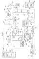
- FIG. 2 is a block diagram of an example configuration implementing an ANC system.
- FIG. 3 is an example ANC system configured to adjust anti-noise generation based on a volume setting of an audio system.
- FIG. 4 is a flow diagram of an example operation of an ANC system configured to adjust anti-noise generation based on a volume setting of an audio system.
- FIG. 5 is an example ANC system configured to adjust anti-noise generation based on power level of audio system output signals.
- FIG. 6 is a flow diagram of an example operation of an ANC system configured to adjust anti-noise generation based on power level of audio system output signals.
- FIG. 7 is an example ANC system configured to adjust anti-noise generation based on presence of predetermined frequencies in audio output signals.
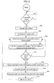
- FIG. 8 is a flow diagram of an example ANC system configured to adjust anti-noise generation based on presence of predetermined frequencies in audio output signals.
- the present disclosure provides a system configured to generate a destructively interfering sound wave and adjust the sound wave based on audio system output. This is accomplished generally by first determining the presence of an undesired sound and generating a destructively interfering sound wave into a target space in which the undesired sound is present. An audio system may also be providing audio output used to generate audio sound waves into the target space. The destructively interfering sound wave may be adjusted based on various conditions associated with the audio output.
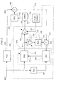
- an example of an active noise control (ANC) system 100 is diagrammatically shown.
- the ANC system 100 may be implemented in various settings, such as a vehicle interior, to reduce or eliminate particular sound frequencies or frequency ranges from being audible by a listener in a target space 102.
- the example ANC system 100 of FIG. 1 is configured to generate signals at one or more desired frequencies or frequency ranges that may be generated as sound waves to destructively interfere with undesired sound 104, represented by a dashed-arrow in FIG. 1 , originating from a sound source 106.
- the ANC system 100 may be configured to destructively interfere with an undesired sound 104 within a frequency range of approximately 20-500 Hz.
- the ANC system 100 may receive a reference signal 107 indicative of sound emanating from the sound source 106 that is audible in the target space 102.
- a sensor such as a microphone 108 may be placed in the target space 102.
- the ANC system 100 may generate an anti-noise signal 110, which in one example may be representative of sound waves of approximately equal amplitude and frequency that are approximately 180 degrees out of phase with the undesired sound 104 present in the target space 102.
- the 180 degree phase shift of the anti-noise signal 110 may cause desirable destructive interference with the undesired sound in an area in which the anti-noise sound waves and the undesired sound 104 sound waves destructively combine.
- the anti-noise signal 110 is shown as being summed at summation operation 112 with an audio signal 114, generated by an audio system 116 to form an output signal 115.
- the output signal 115 is provided to drive a speaker 118 to produce a speaker output 120.
- the speaker output 120 may be an audible sound wave that projected towards the microphone 108 within the target space 102.
- the anti-noise signal 110 component of the sound wave produced as the speaker output 120 may destructively interfere with the undesired sound 104 within the target space 102.
- the audio signal 114 and the anti-noise signal 110 may each drive separate speakers to produce sound waves projected into the target space 102.
- the microphone 108 may generate a microphone output signal 122 based on detection of the combination of the speaker output 120 and the undesired noise 104, as well as other audible signals within range of being received by the microphone 108.
- the microphone output signal 122 may be used as an error signal in order to adjust the anti-noise signal 110.
- the audio system 116 may be generating the audio output signal 114 that may result in driving the speakers, such as the speaker 118, to produce loud enough speaker output within the target space 102 that the undesired sound may be masked, either partially or totally from being audible to a listener.
- the audio-based speaker output results in at least partial masking of the undesired sound 104 in the target space 102, it may be desirable to reduce at least some anti-noise. Due to the masking by the audio system 116, reducing at least some of the anti-noise being produced may be desired because the ANC system 100 may share a common amplifier with the audio system 116.
- the ANC system 100 may receive a signal 119 indicative of the output of the audio system 116.
- the anti-noise system 100 may use the signal 119 to adjust the anti-noise signal 110 generated by an anti-noise generator 121.
- the signal 119 may indicate a volume setting on the audio system 116, such as described in FIG. 3 .
- the ANC system 100 may be configured to reduce or halt generation of anti-noise when the volume reaches some predetermined threshold.
- the signal 119 may indicate other conditions of the audio system 116 such as power level of output signal components within particular frequency ranges.
- an example ANC system 200 and an example physical environment are represented through a block diagram format.
- the ANC system 200 may operate in a manner similar to the ANC system 100 as described with regard to FIG. 1 .
- an undesired sound x(n) may traverse a physical path 204 from a source of the undesired sound x(n) to a microphone 206.
- the physical path 204 may be represented by a Z-domain transfer function P(z).
- the undesired sound x(n) at the microphone 206 may be represented as d(n).
- the undesired sounds x(n) and d(n) represent the undesired sound both physically and as a digital representation that may be produced through use of an analog-to-digital (A/D) converter.
- the undesired sound x(n) may also be used as an input to an adaptive filter 208, which may be included in an anti-noise generator 210.
- the adaptive filter 208 may be represented by a Z-domain transfer function W(z).
- the adaptive filter 208 may be a digital filter configured to be dynamically adapted in order to filter an input signal to produce a desired anti-noise signal 212 as an output signal.
- the adaptive filter 208 receives the undesired sound x(n) as an input signal.
- the anti-noise signal 212 may be used to drive a speaker 215.
- the anti-noise signal 212 may drive the speaker 215 to produce a sound wave.
- the output of the speaker 215 is represented as speaker output 218 in FIG. 2 .
- the speaker output 218 may be a sound wave that travels a physical path 220 that includes a path from the speaker 215 to the microphone 206.
- the physical path 220 may be represented in FIG. 2 by a Z-domain transfer function S(z).
- the speaker output 218 and the undesired noise x(n) may be received by the microphone 206 and a microphone output signal 216 may be generated by the microphone 206. Similar to FIG. 1 , the microphone output signal 216 may serve as an error signal. In other examples, any number of speaker and microphones may be present.
- the anti-noise signal 212 may be adjusted based on the output of the audio system 202
- an audio output signal 221 is shown as being provided by the audio system 202 to the ANC system 200.
- the audio output signal 221 may represent various signals that may be provided by the audio system 202 indicating a particular condition of the audio system 202, such as the volume or output signal power.
- the ANC system 200 may use the audio output signal 221 to adjust the anti-noise signal 212 regardless of the condition of the undesired sound d(n).
- the audio system 202 may also generate an audio output signal (not shown) used to drive a speaker, such as the speaker 215, to produce audio-based sound waves.
- the ANC system 200 may include an anti-noise compensator 222, represented in FIG. 2 as an adjustable gain amplifier having a gain of "G.”
- the anti-noise compensator 222 may adjust the anti-noise signal 212 based on the audio output signal 221 to produce an adjusted anti-noise signal 223.
- the compensator 222 may serve as an "on/off" switch to the ANC system 200.
- the compensator 222 may be configured such that, based on the audio output signal 221, the compensator 222 gain is either one or zero.
- the compensator 222 may have a gain of one until a certain volume threshold of the audio system 202 is reached. While the gain is one, the adjusted anti-noise signal 223 includes the entire anti-noise signal 212. At the threshold, the gain of the compensator 222 would become zero and none of the anti-noise signal 212 would be provided to the speaker 215.
- the gain of the compensator 222 may be adjusted to gain values between zero and one based on the audio output signal 221. Adjustment of the gain varies the adjusted anti-noise signal 223.
- the audio signal 221 may represent a power level of output from the audio system 202 associated with a particular frequency range. As the power level associated with the particular frequency range component of the audio output signal increases, the gain of the compensator 222 may be reduced. The reduction may occur because the audio system 202 may be generating output signals resulting in sound waves within the same frequency range as the undesired sound d(n). Thus, the sound waves based on output from the audio system 202 may mask some of the undesired sound d(n) perceived by a listener resulting in less anti-noise being desired to reduce or eliminate the undesired sound d(n).
- the microphone output signal 216 may be transmitted to a learning algorithm unit (LAU) 224, which may be included in the anti-noise generator 210.
- the LAU 224 may implement various learning algorithms, such as least mean squares (LMS), recursive least mean squares (RLMS), normalized least mean squares (NLMS), or any other suitable learning algorithm.
- LMS least mean squares
- RLMS recursive least mean squares
- NLMS normalized least mean squares
- the LAU 224 also receives as an input the undesired noise x(n) filtered by an estimated path filter 226, which provides an estimated effect on the undesired sound x(n) traversing the physical path 220.
- the estimated path filter 226 may be represented as a Z-domain transfer function S(z).
- LAU output 232 may be an update signal transmitted from the LAU 224 to the adaptive filter 208.
- the adaptive filter 208 generates the anti-noise signal 223 based on the undesired noise x(n) and the LAU output 232.
- the LAU output 232 is transmitted to the adaptive filter 208 to allow the adaptive filter 208 to adjust anti-noise generation based on the microphone output signal 216.
- the microphone output signal 216 may be adjusted in order to compensate for anti-noise adjustment performed by the compensator 222.
- An error compensator 228 may be used to generate an error compensation signal 231.
- the compensated anti-noise signal 223 may be less than the anti-noise signal 212.
- the speaker 215 may be driven to produce a sound wave containing anti-noise lower than that would be produced based on the anti-noise signal 212.
- the microphone output signal 216 would transmit an inaccurate error signal back to the LAU 224 because the LAU 224 would be receiving an error signal based on the compensated anti-noise signal 223 instead of the anti-noise signal 212.
- the adaptive filter 208 would be receiving the LAU output 223, which would not indicate error resulting from the anti-noise signal 212 driving the speaker 215.
- the error compensator 228 includes a gain operator 230, which may be an adjustable gain amplifier, and an estimated path filter 226.
- the gain of the gain operator 230 is "1-G," where G is the gain of the compensator 222.
- the output of the gain operator 230 is input into the filter 226 to produce an error compensation signal 231.
- the error compensation signal 231 is subtracted from the microphone output signal 216 at operator 233 to remove error due to compensation of the anti-noise signal 212 by the compensator 222.
- the output of the operator 233 is a compensated error signal 234 provided to the LAU 224.
- FIG. 3 shows an ANC system 300 configured to generate anti-noise and adjust anti-noise based on audio system output.
- the ANC system 300 may be generated by a computer device 301.
- the computer device 301 may include a processor 303 and a memory 305.
- the memory 305 may be computer-readable storage media or memories, such as a cache, buffer, RAM, removable media, hard drive or other computer readable storage media.
- Computer readable storage media include various types of volatile and nonvolatile storage media.
- Various processing techniques may be implemented by the processor 303 such as multiprocessing, multitasking, parallel processing and the like, for example.
- the ANC system 300 is configured to generate anti-noise to destructively interfere with undesired sound present in a target space 302.
- the ANC system 300 may be configured to be used in a vehicle to eliminate an undesired sound such as engine noise.
- various undesired sounds may be targeted for reduction or elimination such as road noise or any other undesired sound associated with a vehicle.
- Undesired sound may be detected through at least one sensor 304.
- the sensor 304 may be an accelerometer, which may generate an undesired sound signal 308 based on a current operating condition of a vehicle engine indicative of the level of the engine noise.
- Other manners of sound detection may be implemented, such as microphones or any other sensors suitable to detect audible sounds associated with the vehicle or other sound environment.
- the undesired sound signal 308 may be produced by the sensor 304 as an analog signal.
- An analog-to-digital (A/D) converter 309 may digitize the undesired sound signal 308.
- the digitized signal 310 may be provided to a sample rate converter (SRC) 312.
- the SRC 312 may adjust the sample rate of the signal 310.
- the A/D converter 309 may be configured to generate a digitized sample rate of 192 kHz.
- the SRC 312 may reduce the sample rate from 192 kHz to 4 kHz.
- the A/D converter 309 and the SRC 312 may be configured to generate signals of having various sample rates.
- An output signal 314 of the SRC 312 represents the undesired sound and may be provided to an anti-noise generator 316 of the ANC system 300.
- the output signal 314 may also be provided to an estimated path filter 318.
- the estimated path filter 318 simulates the effect of traversing a physical path between the speaker 306 to a microphone 311.
- a filtered output signal 320 may be provided to the anti-noise generator 316.
- the output signal 314 and the filtered output signal 320 may be used by an adaptive filter 322 and LAU 324 of the anti-noise generator 316 in a manner similar to that described in regard to FIG. 2 .
- An audio system 326 may be implemented to generate speaker output intended to be heard within the target space 302.
- the audio system 326 may include a processor 327 and a memory 329.
- the memory 329 may be computer-readable storage media or memories, such as a cache, buffer, RAM, removable media, hard drive or other computer readable storage media.
- Computer readable storage media include various types of volatile and nonvolatile storage media.
- Various processing techniques may be implemented by the processor 327 such as multiprocessing, multitasking, parallel processing and the like, for example.
- the audio system 326 may generate an audio output signal 328.
- the output signal 328 may be generated at a sample rate of 48 kHz.
- the audio output signal 328 may be provided to a SRC 330.
- the SRC 330 may be configured to increase the sample rate of the audio output signal 328.
- the SRC 330 may generate an output signal 332 at a sample rate of 192 kHz.
- the output signal 332 may be provided to a delay operator 334.
- the delay operator 334 delays the audio from being generated as a sound wave to coincide with the associated anti-noise generation processing.
- Output signal 336 of the delay operator 334 represents the audio output signal 328 at a converted sample rate.
- anti-noise produced by the ANC system 300 may be adjusted based on a condition of the audio system 326.
- the anti-noise generator 316 may generate an anti-noise signal 338.
- the anti-noise signal 338 may be adjusted by an anti-noise signal compensator 340 to produce an adjusted anti-noise signal 342.
- the anti-noise signal 338 may be produced at a sample rate of 4 kHz.
- the adjusted anti-noise signal 342 may be provided to a SRC 344.
- the SRC 344 may be configured to increase the sample rate of the adjusted anti-noise signal 342.
- the SRC 344 may adjust the sample rate of the adjusted anti-noise signal 342 from 4 kHz to 192 kHz.
- the SRC 344 may produce an output signal 346, which may represent the adjusted anti-noise signal 342 at an increased sample rate.
- the compensator 340 may adjust the anti-noise signal 338 based on the volume setting of the audio system 326.
- a volume signal 345 may indicate a volume setting of the audio system 326.
- a volume threshold detector 347 may receive the volume signal 345. The threshold detector 347 may provide a threshold indication signal 349 to the anti-noise signal compensator 340.
- the threshold detector 347 may determine when the volume setting of the audio system 326 reaches a predetermined volume setting.
- the predetermined volume setting may represent a setting at which the volume of speaker output based on the audio system 326 masks at least a portion of the undesired sound in the target space 302.
- the threshold indication signal 349 may be provided to the compensator 340 to indicate that the anti-noise signal 338 may be adjusted.
- the compensator 340 may act as an on/off switch, such that none of the anti-noise signal 338 is used to generate anti-noise.
- the threshold indication signal 349 may indicate such to the compensator 340, which will allow the entire anti-noise signal 338 to be used as the adjusted anti-noise signal 342.
- the output signal 346 is shown as being summed with the signal 336 at summation operation 348.
- the signals 336, 346 may be summed together to form signal 350 as input for the speaker 306 to produce sound waves containing both audio content and anti-noise.
- the summed signal 350 is provided to a digital-to-analog converter 351 to generate an analog signal 352.
- the analog signal 352 drives the speaker 306 to produce a sound wave representative of the audio output signal 328 and the adjusted anti-noise signal 342.
- signals based on output from the audio system 326 may be provided to speakers other than speaker 306 to produce sounds waves based on the output signal 328 of the audio system 326.
- the output signal 346 may be provided directly to the D/A converter 351 without use of the summation operation 348.
- the sound waves generated by the speaker 306 may be projected towards the target space 302.
- the microphone 311 may be positioned within the target space 302.
- the microphone 311 may detect sound waves in the target space 302 resulting from the combination of anti-noise and undesired sound.
- the detected sound waves may cause the microphone 311 to generate a microphone output signal, which may be used as an error signal 356 indicating a difference between the anti-noise and undesired sound proximate to the microphone 311.
- the error signal 356 may be provided to an A/D converter 358.
- the A/D converter 358 may generate a digitized error signal 360.
- the A/D converter 358 may digitize the error signal 356 at a sample rate of 192 kHz.
- the error signal 360 may be provided to a SRC 362.
- the SRC 362 may be configured to reduce the sample rate of the error signal 356.
- the SRC 362 may produce an output signal 364 at a sample rate of 4 kHz.
- the output signal 364 may represent the error signal 360 at a reduced sample rate.
- the output signal 364 may be provided to an error compensator 366.
- compensating the anti-noise signal 338 may cause a difference between the anti-noise that may be generated based on the anti-noise signal 338 and that generated based on the adjusted anti-noise signal 346.
- the error adjustment compensator 366 may adjust the output signal 364 to provide an adjusted error signal 368 to the anti-noise generator 316.
- the adjusted error signal 368 may represent a possible error signal arising from combining anti-noise based on the anti-noise signal 338 and the undesired sound in the target space 302.
- the anti-noise generator 316 may continue to generate the anti-noise signal 338 without being affected by the adjustment of the anti-noise signal 338.
- the error compensator 366 may receive the threshold indicator signal 349 causing the error compensation operator 366 and the adjustor 340 to operate in parallel, such that both are "on,” which allows anti-noise to be produced based on the anti-noise signal 338 or "off", which may block any error signal from being received by the anti-noise generator 316.
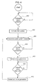
- FIG. 4 is a flow diagram of an example operation of an ANC system, such as the ANC system 300 of FIG. 3 .
- a step 400 may include determining if an undesired sound is present.
- the determination of the step 400 may represent an ANC system configured to operate upon presence of an undesired sound without an active decision required by the ANC system. If no undesired sound is present, step 400 may continuously be performed until the undesired sound is present.
- the ANC system 300 begins generating anti-noise upon detection of the undesired sound through the sensor 304. If the undesired sound is present, a step 402 of activating an ANC system may be performed.
- the step 402 may include automatic production of anti-noise based on the presence of the undesired sound in a manner such as that described with regard to the ANC system 300.
- a step 404 may be performed of determining an audio system volume.
- a step 406 of determining if the volume is above a predetermined threshold is performed.
- An audio system may produce an output signal indicative of the volume setting of the audio system.
- a volume threshold detector may be used, such as the volume threshold detector 347 in FIG. 3 .
- the predetermined volume threshold may be selected for comparison to a current audio system volume setting. If a current volume setting is not above the predetermined volume threshold, the step 404 may be performed to determine the audio system volume. If the volume is determined to be above the predetermined volume threshold, a step 408 of halting anti-noise generation may be performed.
- halting generation of anti-noise may occur through operating the compensator 340, which may attenuate the anti-noise signal 328 such that the anti-noise signal 328 does not reach any speaker for the generation of anti-noise.
- the operation may include a step 410 of determining if the audio system volume is below the predetermined threshold. If the volume is below the predetermined threshold, the halting of anti-noise generation may be maintained. If the volume is determined to be below the predetermined threshold, the generation of the anti-noise may be restarted at a step 412.
- the step 412 may be performed in an ANC system such as the ANC system 300 by operating the anti-noise signal compensator 340 to allow the anti-noise signal 328 to drive the speaker 306 in order to generate anti-noise.
- the error compensator 366 may also be operated in steps 408 and 412 as described with regard to FIG. 3 .
- the step 404 may be performed of determining the audio system volume. The audio system volume may be continuously determined allowing the anti-noise to be halted and restarted based on the volume setting of the audio system.
- FIG. 5 shows an example ANC system 500 configured to adjust anti-noise generation based on a condition of the audio system 326.
- the ANC system 500 may be generated by the computer device 301 similar to that described with regard to the ANC system 300.
- the ANC system 500 may be configured to adjust anti-noise generation based on the power level of output signal components of the audio output signal 328.
- the ANC system 500 may adjust anti-noise generation based on audio system output signals having signal components within a predetermined frequency range.
- the ANC system 500 may be configured to implement components similar to those used in the ANC system 300. Like reference numbers may be used with regard to FIG. 5 to indicate such similarity.
- the audio system 326 generates an audio output signal 328, which may be processed to drive a speaker, such as the speaker 306.
- the audio output signal 328 may include various frequencies components.
- a particular frequency range of the audio output signal 328 may mask an undesired sound, as perceived by a listener, in the target space 302 when used to drive a speaker to provide sound waves to the target space 302.
- the ANC system 500 may be configured to generate anti-noise to destructively interfere with an undesired sound in a frequency range of 20-500 Hz.
- the ANC system 500 may be configured to isolate the frequencies in the audio output signal 328 within the frequency range of the undesired noise and adjust anti-noise generation based on the presence of the isolated frequencies in the audio output signal 328.
- the ANC system 500 may be configured to adjust the generated anti-noise based on the power level of particular signal frequencies within the audio output signal 328.
- a SRC 502 may receive the audio output signal 328 to reduce the sample rate of the audio output signal 328. In the example of FIG. 5 , the sample rate may be reduced from 48 kHz to 4 kHz.
- the output signal 504 of the SRC 502 may be provided to a low pass filter 506.
- the low pass filter 506 may filter the output signal 504 to isolate a desired frequency range of the output signal 504.
- the output signal 508 of the low pass filter 506 may be analyzed to determine the power associated with frequencies within a predetermined frequency range.
- the power of the output signal 504 within particular frequency ranges may indicate the loudness of a particular frequency range in the target space 302 when used to drive a speaker to produce sound waves that may travel to the target space 302.
- a level detector 510 may receive the output signal 508 from the low pass filter 506.
- the level detector 510 may be configured to determine the power level associated with the signal frequencies passing through the low pass filter 506 and generating an output signal 512 indicative of the determined power level.
- the level detector 510 may be a quasi-peak detector configured to determine when a signal is at a particular level for a predetermined amount of time.
- the level detector 510 may be configured to perform in a "catch-and-release" mode in which the level detector 510 may monitor the output signals over windows of time.
- the level detector 510 may monitor each window to determine the power level of the output signal 508 for a predetermined amount of time prior to monitoring the next window of time.
- the level detector 510 may generate an output signal 512 indicating the power level of the output signal 508.
- the ANC system 500 may include the anti-noise generator 316, which receives the output signals 314 and 320 as input signals for use in generating the anti-noise signal 514.
- the anti-noise signal 514 may be adjusted based on the power output signal 512.
- An anti-noise signal compensator 516 may receive the anti-noise signal 514.
- the compensator 516 may receive the anti-noise signal 514 and adjust the anti-noise signal 514 based on the output of the detector 510 to generate an adjusted anti-noise signal 518.
- the adjusted anti-noise signal 518 may be received by the SRC 344 to increase the sample rate to 192 kHz and generate an output signal 520, which may be combined with output signal 350 to form signal 521.
- the signal 521 may be provided to the D/A converter 351 to produce an analog signal 523 to drive the speaker 306 to generate anti-noise into the target space 302.
- the output signal 350 may be used to drive speakers other than the speaker 306, which may allow the output signal 520 to be provided directly to the D/A converter 351.
- the compensator 516 may be configured to vary adjustment of the anti-noise signal 514 based on the output signal 512.
- the output signal 512 is indicative of the power level of the output signal 508.
- the compensator 516 may be configured similar to the compensator 222 of FIG. 2 allowing the amplitude of the anti-noise signal to be reduced based on the output signal 512. As the power associated with the signal 508 increases, the anti-noise may be further reduced. Thus, the output signal 512 may be used as a control signal to adjust the gain of the compensator 516.
- a volume threshold detector 511 may be used in manner similar to the voltage threshold detector 347.
- the volume threshold detector 511 may receive a volume signal 513 indicating the volume of the audio system 326.
- the volume threshold detector 511 may generate a volume threshold signal 515 indicative of the volume setting of the audio system 326.
- the volume threshold signal 515 may be provided to the level detector 510. If the volume setting of the audio system 326 is below a predetermined volume threshold, the level detector 510 determine that the anti-noise signal 514 should not be adjusted because the volume of the audio system is low enough that it would not mask the undesired sound in the target space 302. If the volume is above the predetermined threshold, the level detector 510 may provide the signal 512 for anti-noise signal adjustment.
- An error compensator 522 may be configured to adjust an error signal to compensate for the adjustment of the anti-noise signal 514.
- adjustment of the anti-noise downstream of the anti-noise generator 316 may cause an error signal to be detected by the microphone 311 that would cause the anti-noise generator 316 to generate an undesired anti-noise signal 514.
- the error signal may be adjusted accordingly.
- sound detected by the microphone 311 in the target space 302 may result in a microphone output signal 524 being generated.
- the output signal 524 may be digitized by A/D converter 358 to produce a digitized error signal 526.
- the error signal 526 may be provided to SRC 362 to decrease the sample rate.
- the SRC 362 may generate an output signal 528. In FIG. 5 , the SRC 362 decreases the sample rate of the error signal 526 from 192 kHz to 4 kHz.
- the anti-noise signal 514 may be provided to the error compensator 522.
- the error compensator 522 may be configured similar to the error compensator 228 of FIG. 2 .
- the gain of the error compensator 522 may be adjusted based on the output signal 512 to one minus the gain of the anti-noise signal compensator 516.
- the error compensator 522 may further process the anti-noise signal 514 to generate an error compensation signal 530, which may be removed from the output signal 528 at operator 531 to generate an adjusted error signal 532.
- the adjusted error signal 532 may be provided to the anti-noise generator 316 to be used in generating the anti-noise signal 514.
- FIG. 6 is a flow diagram of an example operation of an ANC system configured to adjust anti-noise generation based on the power of an audio output signal of an audio system.
- the operation may include a step 600 of determining if an undesired sound is present. Similar to the operation of FIG. 4 , the step 600 may be performed passively through a sensor, such as the sensor 304. If an undesired sound is present, the operation may include a step 602 of activating the ANC system to generate anti-noise, which may occur automatically upon the presence of a targeted undesired sound.
- the operation may include a step 604 of filtering an audio system output signal, such as the audio output signal 326.
- the audio output signal 326 may be filtered by the low pass filter 506.
- the operation may include a step 606 of determining the power of the filtered signal.
- a level detector 510 may receive the filtered output signal 508 and determine the power, or amplitude, of the filtered output signal.
- the level detector 510 may be configured to generate an output signal 512 indicative of the power associated with the filtered output signal 508 for a particular window of time.
- the signal 512 may vary as the power of the output signal 508 varies.
- the operation may include a step 608 of determining if the volume of the audio system is above a predetermined threshold.
- volume setting of the audio system 326 may be monitored. Prior to reaching a predetermined volume setting, the volume setting may be so low that audio speaker output based on the audio system 326 may not be loud enough to mask an undesired sound in the target space 302. Thus, until the predetermined threshold is reached by the volume setting, the anti-noise generator 316 may continue to generate the anti-noise signal 514 without adjustment. If the volume setting is above the predetermined threshold, a step 610 of adjusting the anti-noise signal based on the power of the filtered audio output signal may be performed.
- step 610 may be performed by the anti-noise compensator 516.
- the anti-noise compensator 516 may reduce the amplitude of the anti-noise signal 514 based on the signal 512. As the power of the output signal 508 increases, the signal 512 indicates the compensator 516 may further reduce the anti-noise signal 514 amplitude.
- the operation may further include a step 612 of generating anti-noise based on the adjusted anti-noise signal.
- the adjusted anti-noise signal 518 may be generated by the compensator 516.
- the adjusted anti-noise signal 518 may be used to drive the speaker 306 to generate sound waves containing anti-noise.
- the operation may further include a step 614 of adjusting an error signal based on the power of the filtered signal.
- the error signal may be adjusted to compensate for the anti-noise signal being adjusted.
- an error compensation signal may be generated based the power of the filtered signal.
- the ANC system 500 includes an error compensator 522 configured to receive the level detector output signal 512 and the anti-noise signal 514.
- the error compensator 522 may generate an error compensation signal 530, which may be subtracted from the error signal 528 to form the adjusted error signal 532 for use by the anti-noise generator 316. Upon adjustment of the error signal, the operation may perform step 604 to continue operation of the ANC system.
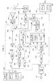
- FIG. 7 shows an example ANC system 700 configured to adjust anti-noise generation based on output from the audio system 326.
- the ANC system 700 is configured to process signals similar to those discussed with regard to FIGS. 3 and 5 . Same reference numbers may be used to refer to the similar signals.
- the ANC system 700 may be generated by the computer device 301.
- the ANC system 700 is configured to adjust anti-noise generation of the anti-noise generator 316 such that particular frequencies and frequency ranges of anti-noise may be reduced based on the audio output signal 328.
- speaker output based on the audio signal 328 may mask an undesired sound in the target space 302.
- the ANC system 700 may be configured to determine particular frequencies present in the audio signal 328 that may mask at least some of the undesired sound.
- the anti-noise signal 702 may be adjusted such that the masking frequencies present in the audio output signal 328 may be reduced or eliminated from the generated anti-noise.
- the undesired sound signal 314 may be provided to an anti-noise signal compensator 704 in order to generate adjusted the anti-noise signal 702.
- the anti-noise compensator 704 may include a plurality of bandpass filters 708, individually designated as BPI through BPX in FIG. 7 .
- the bandpass filters 708 may each be configured for a particular frequency range different from one another. Thus, as the undesired sound signal 314 is provided to the compensator 704, each bandpass filter 708 will allow a particular frequency range to pass when present in the anti-noise signal 702.
- Each of the bandpass filters 708 may have an adjustable gain allowing each filter to reduce or eliminate a particular range of signal frequencies present in the undesired noise signal 314. Signals passing through the bandpass filters 708 may be summed at summation operation 710 to form an adjusted input signal 712.
- the adjusted input signal 712 may be used to generate anti-noise configured to eliminate undesired sounds that may not be masked by the audio-based sound waves.
- Adjusting the gain of the bandpass filters 708 allows selected frequency signal components present in the undesired sound signal 314 to be reduced in amplitude when audio being played in the target space 302 contains sound that masks the selected frequency components.
- the gain of the bandpass filters 708 may be adjusted based on the frequency content of the audio output signal 328.
- the output signal 332 may be provided to a frequency analyzer 716.
- the frequency analyzer 716 may analyze the audio output signal 332 to determine various signal frequencies present in the audio output signal 328.
- the frequency analyzer 716 may generate a plurality of output signals, with each output signal OS 1 through OSX corresponding to one of the bandpass filters 708.
- the frequency analyzer 716 may determine the frequency content of the output signal 332, as well as the intensity level of the signal frequency components.
- the output signals OSI through OSX may each be used as a control signal to adjust the gain of the corresponding bandpass filter 708.
- the bandpass filter 708 corresponding to the particular frequency or frequency range may be reduced in order to reduce the particular frequency or frequency range component amplitude of the signal 314, and consequently, the anti-noise signal 702.
- the ANC system 700 may include a volume threshold detector (not shown), such as the volume threshold detector 347.
- the volume threshold detector 347 may provide a signal to the frequency analyzer 716 indicated the volume is above predetermined threshold such that the audio is loud enough that adjustment of the anti-noise is desired.
- the frequency analyzer 716 may be configured to perform a spectral analysis of the output signal 332.
- the frequency analyzer 716 may be configured to gather blocks of samples of the output signal 332 to perform a fast Fourier transform (FFT) of the block of samples of the output signal 714. Performing the FFT allows a number of frequency bands to be established and each sample analyzed by the frequency analyzer 716 may be associated with one of the frequency bands. The number of samples selected for each analyzed block may be determined by the sample rate of the signal 332. In FIG. 7 , the sample rate of the output signal 332 is 192 kHz.
- FFT fast Fourier transform
- Allowing a block of 128 samples would allow a bandwidth from 0 to approximately 750 Hz of undesired sound to be targeted by the ANC system 700.
- a plurality of sample blocks may be provided to the frequency analyzer 716 prior to the output signals OSI through OSX being generated.
- the frequency analyzer 716 may determine averages over the plurality of blocks to determine if particular frequencies will remain for a particular duration of time or are transient in nature.
- the frequency analyzer 716 may not produce an output signal for a frequency determined to be transient in nature.
- each frequency band of the frequency analyzer 716 may be used to generate a respective output signal OSI through OSX.
- the frequency analyzer 716 may include a predetermined threshold associated with each frequency band, such that no output signal will be generated from the frequency analyzer 716 unless the amplitude for a particular frequency band is above the predetermined threshold.
- Each frequency band of the frequency analyzer 716 may correspond to one of the bandpass filters 704.
- the anti-noise signal 702 may be provide to SRC 344 which may increase the sample rate of anti-noise signal 702 and generate an output signal 709.
- the sample rate of the anti-noise signal 702 may be increased from 4 kHz to 192 kHz.
- the adjusted anti-noise signal 709 may be combined with the output signal 336 to form the output signal 711.
- the output signal 711 may be provided to the D/A converter 351, which may generate an analog signal 713 to drive the speaker 306 to generate anti-noise, as well as audio, into the target space 302.
- the microphone 311 may detect sound waves resulting from anti-noise destructively interfering with undesired sound in the target space 302. If the anti-noise signal 702 is adjusted through the compensator 704, more error may result because the anti-noise has been reduced due to the presence of audio having masking frequencies. While a listener may not hear the undesired sound due to masking, the microphone may detect the undesired sound not destructively interfered with due to adjustment of the anti-noise signal 708.
- a microphone output signal 718 may be digitized by the A/D converter 358 and used as an error signal 720.
- the error signal 720 may be provided to the SRC 362 to decrease the sample rate, similar to that described in FIG. 5 .
- the SRC 362 may generate an output signal 721, which is a decreased sample rate version of the error signal 720.
- the output signal 721 may be adjusted to compensate for the adjustment of the anti-noise signal by the compensator 704.
- the signal 721 may be provided to an error compensator 722.
- the error compensator 722 may include a plurality of bandpass filters 724, individually designated as EBP I through EBPX. Each bandpass filter 724 is configured to have a passband corresponding to those of the bandpass filters 708.
- the signal 721 may be broken into frequency bands by the bandpass filters 724.
- Each of the bandpass filters 724 may have an adjustable gain.
- Each bandpass filter 724 may be adjusted based on the corresponding output signal OSI through OSX.
- Each output signal OSI through OSX may be used to adjust the gain to reduce the frequencies present in the error signal 320 that were reduced or eliminated from the undesired sound signal 314.
- the output signals of each bandpass filter 724 may be summed at summation operation 726 to form a compensated error signal 728.
- the compensated error signal 728 may be provided to the anti
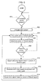
- FIG. 8 is a flow diagram of an example operation of an ANC system configured to adjusted generated anti-noise based on particular frequencies present in an output signal of an audio system.
- the operation may include a step 800 of determining if an undesired sound is present. Similar to the operations of FIGS. 4 and 6 , step 800 may be passively performed through a sensor, such as the sensor 304. If the undesired sound is not detected, step 800 may be continuously performed until the undesired sound is present. Upon presence of the undesired sound, the operation may perform a step 802 of activating an ANC system, such as the ANC system 700.
- an ANC system such as the ANC system 700.
- the operation may include a step 804 of generating an anti-noise signal based on the undesired sound, such as through the anti-noise generator 316.
- the operation may include a step 806 of determining frequency components of audio output signals.
- the ANC system 700 may include a frequency analyzer 716, which includes output signal 714, which is the audio output signal 328 at a reduced sample rate.
- the frequency analyzer 716 may be configured to determine frequency components of output signal 714, such as particular frequency ranges.
- the operation may include a step 808 of filtering an undesired sound signal into a plurality of frequency-based components.
- the undesired sound signal may be provided to a plurality of adjustable gain filters to break the undesired sound signal into various frequency range components, such as the bandpass filters 708 of FIG. 7 .
- the operation may include a step 810 of determining if undesired sound frequencies are present in the audio output signal.
- the frequency analyzer may be configured to determine if particular frequency ranges are present in within an encompassing frequency range such as 20-500 Hz. If none of the undesired sound frequencies are present in the audio output signal, step 806 may be performed. If undesired sound frequency components are present, a step 812 of adjusting amplitude of selected frequency-based undesired sound components.
- an undesired sound signal such as the undesired sound signal 314 may be provided to a plurality of bandpass filters 708.
- the bandpass filters 708 may each be configured to allow a particular frequency range to pass through. Each bandpass filter 708 may be configured to adjust the amplitude of the signals passed through. The amplitude adjustment may be performed based on the frequency components present in the audio output signal 332 as determined by the frequency analyzer 716.
- the operation may include a step 814 of generating an adjusted anti-noise signal.
- the adjusted anti-noise signal may be generated based on an adjusted undesired sound signal.
- the adjusted undesired sound signal may be generated by an anti-noise signal compensator, such as the compensator 704.
- the compensator 704 may provide an adjusted input signal 712.
- Each bandpass filter 708 may receive a gain adjustment signal from the frequency analyzer 716.
- the operation may further include a step 816 of generating anti-noise based on the anti-noise signal.
- the operation may further include a step 818 of adjusting an error signal.
- an error signal provided to the anti-noise generator 316 may be adjusted to compensate for the adjustment of the anti-noise signal 702.
- the output signal 721 representative of the error may be adjusted.
- the error signal 720 may be provided to an error compensator 722, which may include a plurality of bandpass filters 724 to receive the anti-noise signal 702.
- Each bandpass filter 724 may receive a signal from frequency analyzer 716 that adjusts gain of a respective filter 724 based on a respective signal OSI through OSX.
- Each bandpass filter 724 corresponds to one of the bandpass filters 708.
- each filter 724 are summed at summation operation 726 in FIG. 7 , for example.
- the output of the summation operation 728 is a compensated error signal 728, which is provided to the anti-noise generator 316.
- the compensated error signal 728 may be provide to the anti-noise generator 316 to be used by the LAU 324 in manner similar to that described with regard to FIG. 2 .
- step 806 may be performed.
Abstract
Description
- This invention relates to active noise control, and more specifically to active noise control used with an audio system.
- Active noise control may be used to generate sound waves that destructively interfere with a targeted sound. The destructively interfering sound waves may be produced through a loudspeaker to combine with the targeted sound. Active noise control may be desired in a situation in which audio sound waves, such as music, may be desired as well. An audio/visual system may include various loudspeakers to generate audio. These loudspeakers may be used simultaneously to produce destructively interfering sound waves.
- Destructively-interfering sound waves may be generated by an ANC system operating through an amplifier being used by an audio/visual system. Sound waves based on the audio/video system output may be loud enough to mask the targeted sound from being heard by a listener. While destructively-interfering waves may be combining with a targeted sound, at least a portion of the targeted sound may not have been heard by a listener due to audio-based sound waves. Thus, at least a portion of the destructively-interfering sound waves may not be required since the undesired sound is already inaudible to the listener due to the masking. The amplitude or frequency content of the destructively-interfering sound waves may be adjusted to allow more power from the amplifier to be dedicated to the audio/video system. Therefore, a need exists to adjust destructively interfering sound waves generated by an active noise control system based on audio/visual system output.
- An active noise control (ANC) system may generate at least one anti-noise signal to drive one or more respective speakers. The speakers may be driven to generate sound waves to destructively interfere with undesired sound present in at least one targeted listening space. The ANC system may generate the anti-noise signals based on at least one input signal representative of the undesired sound. At least one microphone may detect sound waves resulting from the combination of the generated sound waves and the undesired sound. The microphone may generate an error signal based on detection of the combined generated sound waves and the undesired sound waves. The ANC system may receive the error signal and adjust the anti-noise signal based on the error signal.
- The ANC system may be configured to adjust at least one anti-noise signal based on output from an audio system. The ANC system may adjust the at least one anti-noise signal based on a volume setting of the audio system. The ANC system may reduce the amplitude of the at least one anti-noise signal based on a predetermined volume threshold. The error signal may be adjusted to compensate for the adjustment of the anti-noise based on the output from the audio system.
- The ANC system may be configured to adjust the at least one anti-noise signal based on a power level of an output signal of the audio system. An audio system output signal may be filtered to isolate at least one predetermined frequency or frequency range. The power level associated with the at least one predetermined frequency or frequency range may be determined. The ANC system may adjust the anti-noise signal based on the determined power level. The error signal may be adjusted to compensate for the adjustment of the at least one anti-noise signal based on the determined power level.
- The ANC system may be configured to adjust the at least one anti-noise signal based on the frequency content of an output signal of the audio system. The output signal may be analyzed to determine at least one frequency or frequency range present in the output signal of the audio system. The ANC system may be configured to filter the at least one input signal based on the at least one frequency or frequency range present in the output signal of the audio system. The ANC system may adjust the at least one anti-noise signal based on the filtered input signal. The error signal may be adjusted to compensate for the adjustment of the anti-noise signal based on the filtered input signal.
- Other systems, methods, features and advantages of the invention will be, or will become, apparent to one with skill in the art upon examination of the following figures and detailed description. It is intended that all such additional systems, methods, features and advantages be included within this description, be within the scope of the invention, and be protected by the following claims.
- The system may be better understood with reference to the following drawings and description. The components in the figures are not necessarily to scale, emphasis instead being placed upon illustrating the principles of the invention. Moreover, in the figures, like referenced numerals designate corresponding parts throughout the different views.
-
FIG. 1 is a diagrammatic view of an example active noise cancellation (ANC) system. -
FIG. 2 is a block diagram of an example configuration implementing an ANC system. -
FIG. 3 is an example ANC system configured to adjust anti-noise generation based on a volume setting of an audio system. -
FIG. 4 is a flow diagram of an example operation of an ANC system configured to adjust anti-noise generation based on a volume setting of an audio system. -
FIG. 5 is an example ANC system configured to adjust anti-noise generation based on power level of audio system output signals. -
FIG. 6 is a flow diagram of an example operation of an ANC system configured to adjust anti-noise generation based on power level of audio system output signals. -
FIG. 7 is an example ANC system configured to adjust anti-noise generation based on presence of predetermined frequencies in audio output signals. -
FIG. 8 is a flow diagram of an example ANC system configured to adjust anti-noise generation based on presence of predetermined frequencies in audio output signals. - The present disclosure provides a system configured to generate a destructively interfering sound wave and adjust the sound wave based on audio system output. This is accomplished generally by first determining the presence of an undesired sound and generating a destructively interfering sound wave into a target space in which the undesired sound is present. An audio system may also be providing audio output used to generate audio sound waves into the target space. The destructively interfering sound wave may be adjusted based on various conditions associated with the audio output.
- In
FIG. 1 , an example of an active noise control (ANC)system 100 is diagrammatically shown. The ANCsystem 100 may be implemented in various settings, such as a vehicle interior, to reduce or eliminate particular sound frequencies or frequency ranges from being audible by a listener in atarget space 102. The example ANCsystem 100 ofFIG. 1 is configured to generate signals at one or more desired frequencies or frequency ranges that may be generated as sound waves to destructively interfere withundesired sound 104, represented by a dashed-arrow inFIG. 1 , originating from asound source 106. In one example, the ANCsystem 100 may be configured to destructively interfere with anundesired sound 104 within a frequency range of approximately 20-500 Hz. The ANCsystem 100 may receive areference signal 107 indicative of sound emanating from thesound source 106 that is audible in thetarget space 102. - A sensor such as a
microphone 108 may be placed in thetarget space 102. The ANCsystem 100 may generate ananti-noise signal 110, which in one example may be representative of sound waves of approximately equal amplitude and frequency that are approximately 180 degrees out of phase with theundesired sound 104 present in thetarget space 102. The 180 degree phase shift of theanti-noise signal 110 may cause desirable destructive interference with the undesired sound in an area in which the anti-noise sound waves and theundesired sound 104 sound waves destructively combine. - In
FIG. 1 , theanti-noise signal 110 is shown as being summed atsummation operation 112 with anaudio signal 114, generated by anaudio system 116 to form anoutput signal 115. Theoutput signal 115 is provided to drive aspeaker 118 to produce aspeaker output 120. Thespeaker output 120 may be an audible sound wave that projected towards themicrophone 108 within thetarget space 102. Theanti-noise signal 110 component of the sound wave produced as thespeaker output 120 may destructively interfere with theundesired sound 104 within thetarget space 102. In alternative examples, theaudio signal 114 and theanti-noise signal 110 may each drive separate speakers to produce sound waves projected into thetarget space 102. - The
microphone 108 may generate amicrophone output signal 122 based on detection of the combination of thespeaker output 120 and theundesired noise 104, as well as other audible signals within range of being received by themicrophone 108. Themicrophone output signal 122 may be used as an error signal in order to adjust theanti-noise signal 110. - In one example, the
audio system 116 may be generating theaudio output signal 114 that may result in driving the speakers, such as thespeaker 118, to produce loud enough speaker output within thetarget space 102 that the undesired sound may be masked, either partially or totally from being audible to a listener. When the audio-based speaker output results in at least partial masking of theundesired sound 104 in thetarget space 102, it may be desirable to reduce at least some anti-noise. Due to the masking by theaudio system 116, reducing at least some of the anti-noise being produced may be desired because theANC system 100 may share a common amplifier with theaudio system 116. Reduction of unnecessary anti-noise being produced may allow more power from the amplifier to be dedicated to theaudio system 116 and may also result in less overall power consumption. In one example, generation of the anti-noise may be adjusted based on the output of theaudio system 116. TheANC system 100 may receive asignal 119 indicative of the output of theaudio system 116. Theanti-noise system 100 may use thesignal 119 to adjust theanti-noise signal 110 generated by ananti-noise generator 121. For example, thesignal 119 may indicate a volume setting on theaudio system 116, such as described inFIG. 3 . TheANC system 100 may be configured to reduce or halt generation of anti-noise when the volume reaches some predetermined threshold. Thus, less anti-noise may be produced once the volume setting of theaudio system 116 is set at a predetermined volume level regardless of the presence of the undesired sound in thetarget space 102. In alternative examples, thesignal 119 may indicate other conditions of theaudio system 116 such as power level of output signal components within particular frequency ranges. - In
FIG. 2 , anexample ANC system 200 and an example physical environment are represented through a block diagram format. TheANC system 200 may operate in a manner similar to theANC system 100 as described with regard toFIG. 1 . In one example, an undesired sound x(n) may traverse aphysical path 204 from a source of the undesired sound x(n) to amicrophone 206. Thephysical path 204 may be represented by a Z-domain transfer function P(z). The undesired sound x(n) at themicrophone 206 may be represented as d(n). InFIG. 2 , the undesired sounds x(n) and d(n) represent the undesired sound both physically and as a digital representation that may be produced through use of an analog-to-digital (A/D) converter. The undesired sound x(n) may also be used as an input to anadaptive filter 208, which may be included in ananti-noise generator 210. Theadaptive filter 208 may be represented by a Z-domain transfer function W(z). Theadaptive filter 208 may be a digital filter configured to be dynamically adapted in order to filter an input signal to produce a desiredanti-noise signal 212 as an output signal. InFIG. 2 , theadaptive filter 208 receives the undesired sound x(n) as an input signal. - Similar to that described in
FIG. 1 , theanti-noise signal 212 may be used to drive aspeaker 215. Theanti-noise signal 212 may drive thespeaker 215 to produce a sound wave. The output of thespeaker 215 is represented asspeaker output 218 inFIG. 2 . Thespeaker output 218 may be a sound wave that travels aphysical path 220 that includes a path from thespeaker 215 to themicrophone 206. Thephysical path 220 may be represented inFIG. 2 by a Z-domain transfer function S(z). Thespeaker output 218 and the undesired noise x(n) may be received by themicrophone 206 and amicrophone output signal 216 may be generated by themicrophone 206. Similar toFIG. 1 , themicrophone output signal 216 may serve as an error signal. In other examples, any number of speaker and microphones may be present. - As similarly discussed with regard to
FIG. 1 , theanti-noise signal 212 may be adjusted based on the output of theaudio system 202, InFIG. 2 , anaudio output signal 221 is shown as being provided by theaudio system 202 to theANC system 200. InFIG. 2 , theaudio output signal 221 may represent various signals that may be provided by theaudio system 202 indicating a particular condition of theaudio system 202, such as the volume or output signal power. TheANC system 200 may use theaudio output signal 221 to adjust theanti-noise signal 212 regardless of the condition of the undesired sound d(n). Theaudio system 202 may also generate an audio output signal (not shown) used to drive a speaker, such as thespeaker 215, to produce audio-based sound waves. - The
ANC system 200 may include ananti-noise compensator 222, represented inFIG. 2 as an adjustable gain amplifier having a gain of "G." Theanti-noise compensator 222 may adjust theanti-noise signal 212 based on theaudio output signal 221 to produce an adjustedanti-noise signal 223. In one example, thecompensator 222 may serve as an "on/off" switch to theANC system 200. For example, thecompensator 222 may be configured such that, based on theaudio output signal 221, thecompensator 222 gain is either one or zero. Thus, if theaudio output signal 221 represented a volume level of theaudio system 202, thecompensator 222 may have a gain of one until a certain volume threshold of theaudio system 202 is reached. While the gain is one, the adjustedanti-noise signal 223 includes the entireanti-noise signal 212. At the threshold, the gain of thecompensator 222 would become zero and none of theanti-noise signal 212 would be provided to thespeaker 215. - In another example, the gain of the
compensator 222 may be adjusted to gain values between zero and one based on theaudio output signal 221. Adjustment of the gain varies the adjustedanti-noise signal 223. In one example, theaudio signal 221 may represent a power level of output from theaudio system 202 associated with a particular frequency range. As the power level associated with the particular frequency range component of the audio output signal increases, the gain of thecompensator 222 may be reduced. The reduction may occur because theaudio system 202 may be generating output signals resulting in sound waves within the same frequency range as the undesired sound d(n). Thus, the sound waves based on output from theaudio system 202 may mask some of the undesired sound d(n) perceived by a listener resulting in less anti-noise being desired to reduce or eliminate the undesired sound d(n). - The
microphone output signal 216 may be transmitted to a learning algorithm unit (LAU) 224, which may be included in theanti-noise generator 210. TheLAU 224 may implement various learning algorithms, such as least mean squares (LMS), recursive least mean squares (RLMS), normalized least mean squares (NLMS), or any other suitable learning algorithm. TheLAU 224 also receives as an input the undesired noise x(n) filtered by an estimatedpath filter 226, which provides an estimated effect on the undesired sound x(n) traversing thephysical path 220. InFIG. 2 , the estimated path filter 226 may be represented as a Z-domain transfer function S(z).LAU output 232 may be an update signal transmitted from theLAU 224 to theadaptive filter 208. Thus, theadaptive filter 208 generates theanti-noise signal 223 based on the undesired noise x(n) and theLAU output 232. TheLAU output 232 is transmitted to theadaptive filter 208 to allow theadaptive filter 208 to adjust anti-noise generation based on themicrophone output signal 216. - When the
compensator 222 has a gain of less than one, themicrophone output signal 216 may be adjusted in order to compensate for anti-noise adjustment performed by thecompensator 222. Anerror compensator 228 may be used to generate anerror compensation signal 231. When thecompensator 222 is used to adjust theanti-noise signal 212, the compensatedanti-noise signal 223 may be less than theanti-noise signal 212. Thus, thespeaker 215 may be driven to produce a sound wave containing anti-noise lower than that would be produced based on theanti-noise signal 212. Themicrophone output signal 216 would transmit an inaccurate error signal back to theLAU 224 because theLAU 224 would be receiving an error signal based on the compensatedanti-noise signal 223 instead of theanti-noise signal 212. Theadaptive filter 208 would be receiving theLAU output 223, which would not indicate error resulting from theanti-noise signal 212 driving thespeaker 215. - The
error compensator 228 includes again operator 230, which may be an adjustable gain amplifier, and an estimatedpath filter 226. The gain of thegain operator 230 is "1-G," where G is the gain of thecompensator 222. The output of thegain operator 230 is input into thefilter 226 to produce anerror compensation signal 231. Theerror compensation signal 231 is subtracted from themicrophone output signal 216 atoperator 233 to remove error due to compensation of theanti-noise signal 212 by thecompensator 222. The output of theoperator 233 is a compensatederror signal 234 provided to theLAU 224. -
FIG. 3 shows anANC system 300 configured to generate anti-noise and adjust anti-noise based on audio system output. In one example, theANC system 300 may be generated by acomputer device 301. Thecomputer device 301 may include aprocessor 303 and amemory 305. Thememory 305 may be computer-readable storage media or memories, such as a cache, buffer, RAM, removable media, hard drive or other computer readable storage media. Computer readable storage media include various types of volatile and nonvolatile storage media. Various processing techniques may be implemented by theprocessor 303 such as multiprocessing, multitasking, parallel processing and the like, for example. - In
FIG. 3 , theANC system 300 is configured to generate anti-noise to destructively interfere with undesired sound present in atarget space 302. In one example, theANC system 300 may be configured to be used in a vehicle to eliminate an undesired sound such as engine noise. However, various undesired sounds may be targeted for reduction or elimination such as road noise or any other undesired sound associated with a vehicle. Undesired sound may be detected through at least onesensor 304. In one example, thesensor 304 may be an accelerometer, which may generate anundesired sound signal 308 based on a current operating condition of a vehicle engine indicative of the level of the engine noise. Other manners of sound detection may be implemented, such as microphones or any other sensors suitable to detect audible sounds associated with the vehicle or other sound environment. - The
undesired sound signal 308 may be produced by thesensor 304 as an analog signal. An analog-to-digital (A/D)converter 309 may digitize theundesired sound signal 308. Thedigitized signal 310 may be provided to a sample rate converter (SRC) 312. TheSRC 312 may adjust the sample rate of thesignal 310. In one example, the A/D converter 309 may be configured to generate a digitized sample rate of 192 kHz. TheSRC 312 may reduce the sample rate from 192 kHz to 4 kHz. In alternative examples, the A/D converter 309 and theSRC 312 may be configured to generate signals of having various sample rates. - An
output signal 314 of theSRC 312 represents the undesired sound and may be provided to ananti-noise generator 316 of theANC system 300. Theoutput signal 314 may also be provided to an estimatedpath filter 318. The estimated path filter 318 simulates the effect of traversing a physical path between thespeaker 306 to amicrophone 311. A filteredoutput signal 320 may be provided to theanti-noise generator 316. Theoutput signal 314 and the filteredoutput signal 320 may be used by anadaptive filter 322 andLAU 324 of theanti-noise generator 316 in a manner similar to that described in regard toFIG. 2 . - An
audio system 326 may be implemented to generate speaker output intended to be heard within thetarget space 302. Theaudio system 326 may include aprocessor 327 and amemory 329. Thememory 329 may be computer-readable storage media or memories, such as a cache, buffer, RAM, removable media, hard drive or other computer readable storage media. Computer readable storage media include various types of volatile and nonvolatile storage media. Various processing techniques may be implemented by theprocessor 327 such as multiprocessing, multitasking, parallel processing and the like, for example. - The
audio system 326 may generate anaudio output signal 328. In one example, theoutput signal 328 may be generated at a sample rate of 48 kHz. Theaudio output signal 328 may be provided to aSRC 330. TheSRC 330 may be configured to increase the sample rate of theaudio output signal 328. In one example, theSRC 330 may generate anoutput signal 332 at a sample rate of 192 kHz. Theoutput signal 332 may be provided to adelay operator 334. Thedelay operator 334 delays the audio from being generated as a sound wave to coincide with the associated anti-noise generation processing.Output signal 336 of thedelay operator 334 represents theaudio output signal 328 at a converted sample rate. - As similarly described with regard to
FIG. 2 , anti-noise produced by theANC system 300 may be adjusted based on a condition of theaudio system 326. Theanti-noise generator 316 may generate ananti-noise signal 338. Theanti-noise signal 338 may be adjusted by ananti-noise signal compensator 340 to produce an adjustedanti-noise signal 342. Theanti-noise signal 338 may be produced at a sample rate of 4 kHz. The adjustedanti-noise signal 342 may be provided to aSRC 344. TheSRC 344 may be configured to increase the sample rate of the adjustedanti-noise signal 342. In one example, theSRC 344 may adjust the sample rate of the adjustedanti-noise signal 342 from 4 kHz to 192 kHz. TheSRC 344 may produce anoutput signal 346, which may represent the adjustedanti-noise signal 342 at an increased sample rate. - In one example, the
compensator 340 may adjust theanti-noise signal 338 based on the volume setting of theaudio system 326. InFIG. 3 , avolume signal 345 may indicate a volume setting of theaudio system 326. Avolume threshold detector 347 may receive thevolume signal 345. Thethreshold detector 347 may provide athreshold indication signal 349 to theanti-noise signal compensator 340. - In
FIG. 3 , thethreshold detector 347 may determine when the volume setting of theaudio system 326 reaches a predetermined volume setting. The predetermined volume setting may represent a setting at which the volume of speaker output based on theaudio system 326 masks at least a portion of the undesired sound in thetarget space 302. InFIG. 3 , thethreshold indication signal 349 may be provided to thecompensator 340 to indicate that theanti-noise signal 338 may be adjusted. InFIG. 3 , thecompensator 340 may act as an on/off switch, such that none of theanti-noise signal 338 is used to generate anti-noise. When the volume setting is below the predetermined threshold, thethreshold indication signal 349 may indicate such to thecompensator 340, which will allow the entireanti-noise signal 338 to be used as the adjustedanti-noise signal 342. - In
FIG. 3 , theoutput signal 346 is shown as being summed with thesignal 336 atsummation operation 348. In one example, thesignals speaker 306 to produce sound waves containing both audio content and anti-noise. InFIG. 3 , the summedsignal 350 is provided to a digital-to-analog converter 351 to generate ananalog signal 352. Theanalog signal 352 drives thespeaker 306 to produce a sound wave representative of theaudio output signal 328 and the adjustedanti-noise signal 342. In alternative examples, signals based on output from theaudio system 326 may be provided to speakers other thanspeaker 306 to produce sounds waves based on theoutput signal 328 of theaudio system 326. In such alternative examples, theoutput signal 346 may be provided directly to the D/A converter 351 without use of thesummation operation 348. - The sound waves generated by the
speaker 306 may be projected towards thetarget space 302. Themicrophone 311 may be positioned within thetarget space 302. Themicrophone 311 may detect sound waves in thetarget space 302 resulting from the combination of anti-noise and undesired sound. The detected sound waves may cause themicrophone 311 to generate a microphone output signal, which may be used as anerror signal 356 indicating a difference between the anti-noise and undesired sound proximate to themicrophone 311. Theerror signal 356 may be provided to an A/D converter 358. The A/D converter 358 may generate a digitizederror signal 360. In one example, the A/D converter 358 may digitize theerror signal 356 at a sample rate of 192 kHz. Theerror signal 360 may be provided to aSRC 362. TheSRC 362 may be configured to reduce the sample rate of theerror signal 356. TheSRC 362 may produce anoutput signal 364 at a sample rate of 4 kHz. Theoutput signal 364 may represent theerror signal 360 at a reduced sample rate. Theoutput signal 364 may be provided to anerror compensator 366. - As similarly discussed with regard to
FIG. 2 , compensating theanti-noise signal 338 may cause a difference between the anti-noise that may be generated based on theanti-noise signal 338 and that generated based on the adjustedanti-noise signal 346. Theerror adjustment compensator 366 may adjust theoutput signal 364 to provide an adjustederror signal 368 to theanti-noise generator 316. The adjustederror signal 368 may represent a possible error signal arising from combining anti-noise based on theanti-noise signal 338 and the undesired sound in thetarget space 302. Thus, theanti-noise generator 316 may continue to generate theanti-noise signal 338 without being affected by the adjustment of theanti-noise signal 338. InFIG. 3 , theerror compensator 366 may receive thethreshold indicator signal 349 causing theerror compensation operator 366 and theadjustor 340 to operate in parallel, such that both are "on," which allows anti-noise to be produced based on theanti-noise signal 338 or "off", which may block any error signal from being received by theanti-noise generator 316. -
FIG. 4 is a flow diagram of an example operation of an ANC system, such as theANC system 300 ofFIG. 3 . Astep 400 may include determining if an undesired sound is present. In one example, the determination of thestep 400 may represent an ANC system configured to operate upon presence of an undesired sound without an active decision required by the ANC system. If no undesired sound is present,step 400 may continuously be performed until the undesired sound is present. For example, theANC system 300 begins generating anti-noise upon detection of the undesired sound through thesensor 304. If the undesired sound is present, astep 402 of activating an ANC system may be performed. Thestep 402 may include automatic production of anti-noise based on the presence of the undesired sound in a manner such as that described with regard to theANC system 300. Upon activation of the ANC system, astep 404 may be performed of determining an audio system volume. - Upon determining the audio system volume, a
step 406 of determining if the volume is above a predetermined threshold is performed. An audio system may produce an output signal indicative of the volume setting of the audio system. In one example, a volume threshold detector may be used, such as thevolume threshold detector 347 inFIG. 3 . The predetermined volume threshold may be selected for comparison to a current audio system volume setting. If a current volume setting is not above the predetermined volume threshold, thestep 404 may be performed to determine the audio system volume. If the volume is determined to be above the predetermined volume threshold, astep 408 of halting anti-noise generation may be performed. In theANC system 300, halting generation of anti-noise may occur through operating thecompensator 340, which may attenuate theanti-noise signal 328 such that theanti-noise signal 328 does not reach any speaker for the generation of anti-noise. - The operation may include a
step 410 of determining if the audio system volume is below the predetermined threshold. If the volume is below the predetermined threshold, the halting of anti-noise generation may be maintained. If the volume is determined to be below the predetermined threshold, the generation of the anti-noise may be restarted at astep 412. In one example, thestep 412 may be performed in an ANC system such as theANC system 300 by operating theanti-noise signal compensator 340 to allow theanti-noise signal 328 to drive thespeaker 306 in order to generate anti-noise. Theerror compensator 366 may also be operated insteps FIG. 3 . Upon performance of thestep 412, thestep 404 may be performed of determining the audio system volume. The audio system volume may be continuously determined allowing the anti-noise to be halted and restarted based on the volume setting of the audio system. -
FIG. 5 shows anexample ANC system 500 configured to adjust anti-noise generation based on a condition of theaudio system 326. TheANC system 500 may be generated by thecomputer device 301 similar to that described with regard to theANC system 300. In one example, theANC system 500 may be configured to adjust anti-noise generation based on the power level of output signal components of theaudio output signal 328. TheANC system 500 may adjust anti-noise generation based on audio system output signals having signal components within a predetermined frequency range. TheANC system 500 may be configured to implement components similar to those used in theANC system 300. Like reference numbers may be used with regard toFIG. 5 to indicate such similarity. - Similar to that described in regard to
FIG. 3 , theaudio system 326 generates anaudio output signal 328, which may be processed to drive a speaker, such as thespeaker 306. Theaudio output signal 328 may include various frequencies components. In one example, a particular frequency range of theaudio output signal 328 may mask an undesired sound, as perceived by a listener, in thetarget space 302 when used to drive a speaker to provide sound waves to thetarget space 302. In one example, theANC system 500 may be configured to generate anti-noise to destructively interfere with an undesired sound in a frequency range of 20-500 Hz. - The
ANC system 500 may be configured to isolate the frequencies in theaudio output signal 328 within the frequency range of the undesired noise and adjust anti-noise generation based on the presence of the isolated frequencies in theaudio output signal 328. TheANC system 500 may be configured to adjust the generated anti-noise based on the power level of particular signal frequencies within theaudio output signal 328. In one example, aSRC 502 may receive theaudio output signal 328 to reduce the sample rate of theaudio output signal 328. In the example ofFIG. 5 , the sample rate may be reduced from 48 kHz to 4 kHz. Theoutput signal 504 of theSRC 502 may be provided to alow pass filter 506. Thelow pass filter 506 may filter theoutput signal 504 to isolate a desired frequency range of theoutput signal 504. - The
output signal 508 of thelow pass filter 506 may be analyzed to determine the power associated with frequencies within a predetermined frequency range. The power of theoutput signal 504 within particular frequency ranges may indicate the loudness of a particular frequency range in thetarget space 302 when used to drive a speaker to produce sound waves that may travel to thetarget space 302. Alevel detector 510 may receive theoutput signal 508 from thelow pass filter 506. Thelevel detector 510 may be configured to determine the power level associated with the signal frequencies passing through thelow pass filter 506 and generating anoutput signal 512 indicative of the determined power level. - In one example, the
level detector 510 may be a quasi-peak detector configured to determine when a signal is at a particular level for a predetermined amount of time. Thelevel detector 510 may be configured to perform in a "catch-and-release" mode in which thelevel detector 510 may monitor the output signals over windows of time. Thelevel detector 510 may monitor each window to determine the power level of theoutput signal 508 for a predetermined amount of time prior to monitoring the next window of time. Thelevel detector 510 may generate anoutput signal 512 indicating the power level of theoutput signal 508. - The
ANC system 500 may include theanti-noise generator 316, which receives the output signals 314 and 320 as input signals for use in generating theanti-noise signal 514. Theanti-noise signal 514 may be adjusted based on thepower output signal 512. Ananti-noise signal compensator 516 may receive theanti-noise signal 514. Thecompensator 516 may receive theanti-noise signal 514 and adjust theanti-noise signal 514 based on the output of thedetector 510 to generate an adjustedanti-noise signal 518. The adjustedanti-noise signal 518 may be received by theSRC 344 to increase the sample rate to 192 kHz and generate anoutput signal 520, which may be combined withoutput signal 350 to formsignal 521. Thesignal 521 may be provided to the D/A converter 351 to produce ananalog signal 523 to drive thespeaker 306 to generate anti-noise into thetarget space 302. In alternative examples, theoutput signal 350 may be used to drive speakers other than thespeaker 306, which may allow theoutput signal 520 to be provided directly to the D/A converter 351. - The
compensator 516 may be configured to vary adjustment of theanti-noise signal 514 based on theoutput signal 512. In one example, theoutput signal 512 is indicative of the power level of theoutput signal 508. Thecompensator 516 may be configured similar to thecompensator 222 ofFIG. 2 allowing the amplitude of the anti-noise signal to be reduced based on theoutput signal 512. As the power associated with thesignal 508 increases, the anti-noise may be further reduced. Thus, theoutput signal 512 may be used as a control signal to adjust the gain of thecompensator 516. - A
volume threshold detector 511 may be used in manner similar to thevoltage threshold detector 347. Thevolume threshold detector 511 may receive avolume signal 513 indicating the volume of theaudio system 326. Thevolume threshold detector 511 may generate avolume threshold signal 515 indicative of the volume setting of theaudio system 326. Thevolume threshold signal 515 may be provided to thelevel detector 510. If the volume setting of theaudio system 326 is below a predetermined volume threshold, thelevel detector 510 determine that theanti-noise signal 514 should not be adjusted because the volume of the audio system is low enough that it would not mask the undesired sound in thetarget space 302. If the volume is above the predetermined threshold, thelevel detector 510 may provide thesignal 512 for anti-noise signal adjustment. - An
error compensator 522 may be configured to adjust an error signal to compensate for the adjustment of theanti-noise signal 514. As previously discussed, adjustment of the anti-noise downstream of theanti-noise generator 316 may cause an error signal to be detected by themicrophone 311 that would cause theanti-noise generator 316 to generate an undesiredanti-noise signal 514. Thus, the error signal may be adjusted accordingly. InFIG. 5 , sound detected by themicrophone 311 in thetarget space 302 may result in amicrophone output signal 524 being generated. Theoutput signal 524 may be digitized by A/D converter 358 to produce a digitizederror signal 526. Theerror signal 526 may be provided toSRC 362 to decrease the sample rate. TheSRC 362 may generate anoutput signal 528. InFIG. 5 , theSRC 362 decreases the sample rate of the error signal 526 from 192 kHz to 4 kHz. - The
anti-noise signal 514 may be provided to theerror compensator 522. In one example, theerror compensator 522 may be configured similar to theerror compensator 228 ofFIG. 2 . The gain of theerror compensator 522 may be adjusted based on theoutput signal 512 to one minus the gain of theanti-noise signal compensator 516. Theerror compensator 522 may further process theanti-noise signal 514 to generate anerror compensation signal 530, which may be removed from theoutput signal 528 atoperator 531 to generate an adjustederror signal 532. The adjustederror signal 532 may be provided to theanti-noise generator 316 to be used in generating theanti-noise signal 514. -
FIG. 6 is a flow diagram of an example operation of an ANC system configured to adjust anti-noise generation based on the power of an audio output signal of an audio system. The operation may include astep 600 of determining if an undesired sound is present. Similar to the operation ofFIG. 4 , thestep 600 may be performed passively through a sensor, such as thesensor 304. If an undesired sound is present, the operation may include astep 602 of activating the ANC system to generate anti-noise, which may occur automatically upon the presence of a targeted undesired sound. - The operation may include a
step 604 of filtering an audio system output signal, such as theaudio output signal 326. In one example, theaudio output signal 326 may be filtered by thelow pass filter 506. The operation may include astep 606 of determining the power of the filtered signal. In one example, alevel detector 510 may receive the filteredoutput signal 508 and determine the power, or amplitude, of the filtered output signal. Thelevel detector 510 may be configured to generate anoutput signal 512 indicative of the power associated with the filteredoutput signal 508 for a particular window of time. Thesignal 512 may vary as the power of theoutput signal 508 varies. - The operation may include a
step 608 of determining if the volume of the audio system is above a predetermined threshold. As described in regard toFIGS. 3-5 , volume setting of theaudio system 326 may be monitored. Prior to reaching a predetermined volume setting, the volume setting may be so low that audio speaker output based on theaudio system 326 may not be loud enough to mask an undesired sound in thetarget space 302. Thus, until the predetermined threshold is reached by the volume setting, theanti-noise generator 316 may continue to generate theanti-noise signal 514 without adjustment. If the volume setting is above the predetermined threshold, astep 610 of adjusting the anti-noise signal based on the power of the filtered audio output signal may be performed. In one example, step 610 may be performed by theanti-noise compensator 516. Theanti-noise compensator 516 may reduce the amplitude of theanti-noise signal 514 based on thesignal 512. As the power of theoutput signal 508 increases, thesignal 512 indicates thecompensator 516 may further reduce theanti-noise signal 514 amplitude. - The operation may further include a
step 612 of generating anti-noise based on the adjusted anti-noise signal. In theANC system 500, the adjustedanti-noise signal 518 may be generated by thecompensator 516. The adjustedanti-noise signal 518 may be used to drive thespeaker 306 to generate sound waves containing anti-noise. The operation may further include astep 614 of adjusting an error signal based on the power of the filtered signal. The error signal may be adjusted to compensate for the anti-noise signal being adjusted. In one example, an error compensation signal may be generated based the power of the filtered signal. For example, theANC system 500 includes anerror compensator 522 configured to receive the leveldetector output signal 512 and theanti-noise signal 514. Theerror compensator 522 may generate anerror compensation signal 530, which may be subtracted from theerror signal 528 to form the adjustederror signal 532 for use by theanti-noise generator 316. Upon adjustment of the error signal, the operation may performstep 604 to continue operation of the ANC system. -
FIG. 7 shows anexample ANC system 700 configured to adjust anti-noise generation based on output from theaudio system 326. InFIG. 7 , theANC system 700 is configured to process signals similar to those discussed with regard toFIGS. 3 and5 . Same reference numbers may be used to refer to the similar signals. TheANC system 700 may be generated by thecomputer device 301. - The
ANC system 700 is configured to adjust anti-noise generation of theanti-noise generator 316 such that particular frequencies and frequency ranges of anti-noise may be reduced based on theaudio output signal 328. In one example, speaker output based on theaudio signal 328 may mask an undesired sound in thetarget space 302. TheANC system 700 may be configured to determine particular frequencies present in theaudio signal 328 that may mask at least some of the undesired sound. Theanti-noise signal 702 may be adjusted such that the masking frequencies present in theaudio output signal 328 may be reduced or eliminated from the generated anti-noise. - Particular frequencies present in an
audio signal 328 may be reduced or eliminated from theundesired sound signal 314 before reach may be reduced or eliminated prior to theanti-noise signal 702 being used to generate anti-noise. Theundesired sound signal 314 may be provided to ananti-noise signal compensator 704 in order to generate adjusted theanti-noise signal 702. Theanti-noise compensator 704 may include a plurality ofbandpass filters 708, individually designated as BPI through BPX inFIG. 7 . The bandpass filters 708 may each be configured for a particular frequency range different from one another. Thus, as theundesired sound signal 314 is provided to thecompensator 704, eachbandpass filter 708 will allow a particular frequency range to pass when present in theanti-noise signal 702. - Each of the
bandpass filters 708 may have an adjustable gain allowing each filter to reduce or eliminate a particular range of signal frequencies present in theundesired noise signal 314. Signals passing through thebandpass filters 708 may be summed atsummation operation 710 to form an adjustedinput signal 712. The adjustedinput signal 712 may be used to generate anti-noise configured to eliminate undesired sounds that may not be masked by the audio-based sound waves. - Adjusting the gain of the
bandpass filters 708 allows selected frequency signal components present in theundesired sound signal 314 to be reduced in amplitude when audio being played in thetarget space 302 contains sound that masks the selected frequency components. The gain of thebandpass filters 708 may be adjusted based on the frequency content of theaudio output signal 328. - The
output signal 332 may be provided to afrequency analyzer 716. Thefrequency analyzer 716 may analyze theaudio output signal 332 to determine various signal frequencies present in theaudio output signal 328. Thefrequency analyzer 716 may generate a plurality of output signals, with eachoutput signal OS 1 through OSX corresponding to one of the bandpass filters 708. Thefrequency analyzer 716 may determine the frequency content of theoutput signal 332, as well as the intensity level of the signal frequency components. The output signals OSI through OSX may each be used as a control signal to adjust the gain of the correspondingbandpass filter 708. Thus, if a particular frequency or frequency range is determined to have a high enough intensity to mask at least a portion of an undesired sound, thebandpass filter 708 corresponding to the particular frequency or frequency range may be reduced in order to reduce the particular frequency or frequency range component amplitude of thesignal 314, and consequently, theanti-noise signal 702. In one example, theANC system 700 may include a volume threshold detector (not shown), such as thevolume threshold detector 347. Thevolume threshold detector 347 may provide a signal to thefrequency analyzer 716 indicated the volume is above predetermined threshold such that the audio is loud enough that adjustment of the anti-noise is desired. - In one example, the
frequency analyzer 716 may be configured to perform a spectral analysis of theoutput signal 332. Thefrequency analyzer 716 may be configured to gather blocks of samples of theoutput signal 332 to perform a fast Fourier transform (FFT) of the block of samples of the output signal 714. Performing the FFT allows a number of frequency bands to be established and each sample analyzed by thefrequency analyzer 716 may be associated with one of the frequency bands. The number of samples selected for each analyzed block may be determined by the sample rate of thesignal 332. InFIG. 7 , the sample rate of theoutput signal 332 is 192 kHz. Allowing a block of 128 samples would allow a bandwidth from 0 to approximately 750 Hz of undesired sound to be targeted by theANC system 700. In one example, a plurality of sample blocks may be provided to thefrequency analyzer 716 prior to the output signals OSI through OSX being generated. Thefrequency analyzer 716 may determine averages over the plurality of blocks to determine if particular frequencies will remain for a particular duration of time or are transient in nature. Thefrequency analyzer 716 may not produce an output signal for a frequency determined to be transient in nature. - The number of samples associated with each frequency band provides the amplitude for a particular frequency band. Thus, each frequency band of the
frequency analyzer 716 may be used to generate a respective output signal OSI through OSX. Thefrequency analyzer 716 may include a predetermined threshold associated with each frequency band, such that no output signal will be generated from thefrequency analyzer 716 unless the amplitude for a particular frequency band is above the predetermined threshold. Each frequency band of thefrequency analyzer 716 may correspond to one of the bandpass filters 704. - The
anti-noise signal 702 may be provide toSRC 344 which may increase the sample rate ofanti-noise signal 702 and generate anoutput signal 709. InFIG. 7 , the sample rate of theanti-noise signal 702 may be increased from 4 kHz to 192 kHz. InFIG. 7 , the adjustedanti-noise signal 709 may be combined with theoutput signal 336 to form theoutput signal 711. Theoutput signal 711 may be provided to the D/A converter 351, which may generate ananalog signal 713 to drive thespeaker 306 to generate anti-noise, as well as audio, into thetarget space 302. - The
microphone 311 may detect sound waves resulting from anti-noise destructively interfering with undesired sound in thetarget space 302. If theanti-noise signal 702 is adjusted through thecompensator 704, more error may result because the anti-noise has been reduced due to the presence of audio having masking frequencies. While a listener may not hear the undesired sound due to masking, the microphone may detect the undesired sound not destructively interfered with due to adjustment of theanti-noise signal 708. Amicrophone output signal 718 may be digitized by the A/D converter 358 and used as anerror signal 720. Theerror signal 720 may be provided to theSRC 362 to decrease the sample rate, similar to that described inFIG. 5 . TheSRC 362 may generate anoutput signal 721, which is a decreased sample rate version of theerror signal 720. - The
output signal 721 may be adjusted to compensate for the adjustment of the anti-noise signal by thecompensator 704. Thesignal 721 may be provided to anerror compensator 722. Theerror compensator 722 may include a plurality ofbandpass filters 724, individually designated as EBP I through EBPX. Eachbandpass filter 724 is configured to have a passband corresponding to those of the bandpass filters 708. Thesignal 721 may be broken into frequency bands by the bandpass filters 724. Each of thebandpass filters 724 may have an adjustable gain. Eachbandpass filter 724 may be adjusted based on the corresponding output signal OSI through OSX. Each output signal OSI through OSX may be used to adjust the gain to reduce the frequencies present in theerror signal 320 that were reduced or eliminated from theundesired sound signal 314. The output signals of eachbandpass filter 724 may be summed at summation operation 726 to form a compensatederror signal 728. The compensatederror signal 728 may be provided to theanti-noise generator 316. -
FIG. 8 is a flow diagram of an example operation of an ANC system configured to adjusted generated anti-noise based on particular frequencies present in an output signal of an audio system. The operation may include astep 800 of determining if an undesired sound is present. Similar to the operations ofFIGS. 4 and6 , step 800 may be passively performed through a sensor, such as thesensor 304. If the undesired sound is not detected,step 800 may be continuously performed until the undesired sound is present. Upon presence of the undesired sound, the operation may perform astep 802 of activating an ANC system, such as theANC system 700. - The operation may include a
step 804 of generating an anti-noise signal based on the undesired sound, such as through theanti-noise generator 316. The operation may include astep 806 of determining frequency components of audio output signals. In one example, theANC system 700 may include afrequency analyzer 716, which includes output signal 714, which is theaudio output signal 328 at a reduced sample rate. Thefrequency analyzer 716 may be configured to determine frequency components of output signal 714, such as particular frequency ranges. - The operation may include a
step 808 of filtering an undesired sound signal into a plurality of frequency-based components. The undesired sound signal may be provided to a plurality of adjustable gain filters to break the undesired sound signal into various frequency range components, such as thebandpass filters 708 ofFIG. 7 . - The operation may include a
step 810 of determining if undesired sound frequencies are present in the audio output signal. In one example, the frequency analyzer may be configured to determine if particular frequency ranges are present in within an encompassing frequency range such as 20-500 Hz. If none of the undesired sound frequencies are present in the audio output signal, step 806 may be performed. If undesired sound frequency components are present, astep 812 of adjusting amplitude of selected frequency-based undesired sound components. In one example, an undesired sound signal, such as theundesired sound signal 314 may be provided to a plurality of bandpass filters 708. The bandpass filters 708 may each be configured to allow a particular frequency range to pass through. Eachbandpass filter 708 may be configured to adjust the amplitude of the signals passed through. The amplitude adjustment may be performed based on the frequency components present in theaudio output signal 332 as determined by thefrequency analyzer 716. - The operation may include a
step 814 of generating an adjusted anti-noise signal. In one example, the adjusted anti-noise signal may be generated based on an adjusted undesired sound signal. The adjusted undesired sound signal may be generated by an anti-noise signal compensator, such as thecompensator 704. Thecompensator 704 may provide an adjustedinput signal 712. Eachbandpass filter 708 may receive a gain adjustment signal from thefrequency analyzer 716. The operation may further include astep 816 of generating anti-noise based on the anti-noise signal. - The operation may further include a
step 818 of adjusting an error signal. As previously described, an error signal provided to theanti-noise generator 316 may be adjusted to compensate for the adjustment of theanti-noise signal 702. In theANC system 700, theoutput signal 721 representative of the error may be adjusted. In theANC system 700, theerror signal 720 may be provided to anerror compensator 722, which may include a plurality ofbandpass filters 724 to receive theanti-noise signal 702. Eachbandpass filter 724 may receive a signal fromfrequency analyzer 716 that adjusts gain of arespective filter 724 based on a respective signal OSI through OSX. Eachbandpass filter 724 corresponds to one of the bandpass filters 708. The outputs of eachfilter 724 are summed at summation operation 726 inFIG. 7 , for example. The output of thesummation operation 728 is a compensatederror signal 728, which is provided to theanti-noise generator 316. The compensatederror signal 728 may be provide to theanti-noise generator 316 to be used by theLAU 324 in manner similar to that described with regard toFIG. 2 . Upon adjustment of the error signal, step 806 may be performed. - While various embodiments of the invention have been described, it will be apparent to those of ordinary skill in the art that many more embodiments and implementations are possible within the scope of the invention. Accordingly, the invention is not to be restricted except in light of the attached claims and their equivalents.
Claims (15)
- A sound reduction system comprising:a processor; andan active noise control system executable by the processor, the active noise control system configured to:where the anti-noise signal is configured to drive a loudspeaker to produce an audible sound to destructively interfere with an undesired sound present in the space.receive a first input signal representative of sound present in a predetermined area;receive a second input signal representative of output produced by an audio system;generate an anti-noise signal based on the first input signal; andadjust the anti-noise signal based on the second input signal;
- The system of claim 1, where the second input signal is representative of the volume setting of the audio system; and
where the active noise control system is further configured reduce the amplitude of the anti-noise signal when the volume setting is above a predetermined threshold. - The system of claim 2, where the active noise control is further configured to halt production of the anti-noise when the volume setting is above the predetermined threshold.
- The system of claim 1, where the active noise control system includes a signal level detector;
where the signal level detector is configured to determine the power level of a predetermined frequency range of the second input signal and generate a third input signal representative of the power level of the predetermined frequency range of the second input signal; and
where the anti-noise signal is adjusted based on the third input signal. - The system of claim 4, where the active noise control system includes an anti-noise signal compensator configured to adjust the anti-noise signal based on the third input signal.
- The system of claim 5, where the anti-noise signal compensator is configured to reduce the amplitude of the anti-noise signal based on third input signal.
- The system of claim 6, where the active noise control signal is further configured to receive an error signal and adjust the anti-noise signal based on the error signal; and
where the active noise control system includes an error compensator configured to adjust the error signal based on the third input signal. - The system of claim 7, where the error compensator is configured to generate an error compensation signal based on the third input signal and the anti-noise signal; and
where the error compensation signal is subtracted from the error signal to adjust the error signal. - A method of reducing volume of an undesired sound present in a space comprising:generating a first input signal representative of the undesired sound present in a predetermined area;receiving a second input signal representative of output produced by an audio system;generating an anti-noise signal based on the first input signal;adjusting the anti-noise signal based on the second input signal; andproducing an audible sound based on the anti-noise signal to destructively interfere with the undesired sound present in the space.
- The method of claim 9, where the second input signal is representative of a volume setting of the audio setting, and where adjusting the anti-noise signal comprises reducing the amplitude of the anti-noise signal when the volume setting is above a predetermined threshold.
- The method of claim 10 further comprising halting production of the audible sound when the volume setting is above the predetermined threshold.
- The method of claim 9, further comprising:determining at least one signal frequency component present in the second input signal; andgenerating a third input signal indicating the presence of the at least one signal frequency component, where adjusting the anti-noise signal comprises adjusting the anti-noise signal based on the third input signal.
- The method of claim 12, further comprising:providing the first input signal to a plurality of filters, where each filter is associated with a respective frequency range;determining a plurality of frequency components present in the second input signal;generating a respective output signal indicating presence of a corresponding frequency component in the second input signal, where each respective output signal is associated with one of the plurality of filters and where each respective output signal is configured to adjust the gain of the associated filter; andproviding each of the plurality of filters with the associated respective output signal.
- The method of claim 13 further comprising:receiving a plurality of samples of the second input signal; anddetermining the frequency components present in the second input signal based on the plurality of samples.
- The method of claim 13 further comprising:generating a filter output signal with each of the plurality of filters;summing the filter outputs to form an adjusted input signal; andadjusting the anti-noise signal based on the adjusted input signal.
Applications Claiming Priority (1)
| Application Number | Priority Date | Filing Date | Title |
|---|---|---|---|
| US12/421,459 US8189799B2 (en) | 2009-04-09 | 2009-04-09 | System for active noise control based on audio system output |
Publications (2)
| Publication Number | Publication Date |
|---|---|
| EP2239728A2 true EP2239728A2 (en) | 2010-10-13 |
| EP2239728A3 EP2239728A3 (en) | 2012-12-19 |
Family
ID=42380391
Family Applications (1)
| Application Number | Title | Priority Date | Filing Date |
|---|---|---|---|
| EP10158376A Withdrawn EP2239728A3 (en) | 2009-04-09 | 2010-03-30 | System for active noise control based on audio system output |
Country Status (4)
| Country | Link |
|---|---|
| US (1) | US8189799B2 (en) |
| EP (1) | EP2239728A3 (en) |
| JP (2) | JP2010244045A (en) |
| CN (1) | CN101859563B (en) |
Cited By (13)
| Publication number | Priority date | Publication date | Assignee | Title |
|---|---|---|---|---|
| WO2014191798A1 (en) | 2013-05-31 | 2014-12-04 | Nokia Corporation | An audio scene apparatus |
| US10152961B2 (en) | 2014-10-16 | 2018-12-11 | Sony Corporation | Signal processing device and signal processing method |
| US10795639B2 (en) | 2012-11-02 | 2020-10-06 | Sony Corporation | Signal processing device and signal processing method |
| CN111971741A (en) * | 2018-05-02 | 2020-11-20 | 哈曼贝克自动系统股份有限公司 | Feed forward active noise control |
| US10896668B2 (en) | 2017-01-31 | 2021-01-19 | Sony Corporation | Signal processing apparatus, signal processing method, and computer program |
| US11166099B2 (en) | 2019-09-27 | 2021-11-02 | Apple Inc. | Headphone acoustic noise cancellation and speaker protection or dynamic user experience processing |
| US11206004B1 (en) | 2020-09-16 | 2021-12-21 | Apple Inc. | Automatic equalization for consistent headphone playback |
| FR3115148A1 (en) | 2020-10-12 | 2022-04-15 | Renault S.A.S | Assembly and method for active rolling noise control for a motor vehicle |
| US11355096B1 (en) | 2020-09-16 | 2022-06-07 | Apple Inc. | Adaptive feedback processing for consistent headphone acoustic noise cancellation |
| US11361745B2 (en) | 2019-09-27 | 2022-06-14 | Apple Inc. | Headphone acoustic noise cancellation and speaker protection |
| US11503409B1 (en) | 2016-09-22 | 2022-11-15 | Apple Inc. | Spatial headphone transparency |
| EP4280208A1 (en) * | 2022-05-18 | 2023-11-22 | Alps Alpine Co., Ltd. | Active noise control system |
| EP2984648B1 (en) * | 2013-04-10 | 2023-12-13 | Cirrus Logic, Inc. | Systems and methods for multi-mode adaptive noise cancellation for audio headsets |
Families Citing this family (67)
| Publication number | Priority date | Publication date | Assignee | Title |
|---|---|---|---|---|
| US8135140B2 (en) | 2008-11-20 | 2012-03-13 | Harman International Industries, Incorporated | System for active noise control with audio signal compensation |
| US9020158B2 (en) | 2008-11-20 | 2015-04-28 | Harman International Industries, Incorporated | Quiet zone control system |
| US8718289B2 (en) | 2009-01-12 | 2014-05-06 | Harman International Industries, Incorporated | System for active noise control with parallel adaptive filter configuration |
| US8189799B2 (en) * | 2009-04-09 | 2012-05-29 | Harman International Industries, Incorporated | System for active noise control based on audio system output |
| JP5244231B2 (en) * | 2009-04-15 | 2013-07-24 | パイオニア株式会社 | SOUND DEVICE, NOISE SOUND CONTROL METHOD, NOISE SOUND CONTROL PROGRAM, AND RECORDING MEDIUM |
| US8199924B2 (en) * | 2009-04-17 | 2012-06-12 | Harman International Industries, Incorporated | System for active noise control with an infinite impulse response filter |
| US8077873B2 (en) | 2009-05-14 | 2011-12-13 | Harman International Industries, Incorporated | System for active noise control with adaptive speaker selection |
| US9099077B2 (en) | 2010-06-04 | 2015-08-04 | Apple Inc. | Active noise cancellation decisions using a degraded reference |
| US8515089B2 (en) * | 2010-06-04 | 2013-08-20 | Apple Inc. | Active noise cancellation decisions in a portable audio device |
| US9275621B2 (en) | 2010-06-21 | 2016-03-01 | Nokia Technologies Oy | Apparatus, method and computer program for adjustable noise cancellation |
| GB2484722B (en) * | 2010-10-21 | 2014-11-12 | Wolfson Microelectronics Plc | Noise cancellation system |
| CN103270552B (en) | 2010-12-03 | 2016-06-22 | 美国思睿逻辑有限公司 | The Supervised Control of the adaptability noise killer in individual's voice device |
| US8908877B2 (en) | 2010-12-03 | 2014-12-09 | Cirrus Logic, Inc. | Ear-coupling detection and adjustment of adaptive response in noise-canceling in personal audio devices |
| US9824677B2 (en) | 2011-06-03 | 2017-11-21 | Cirrus Logic, Inc. | Bandlimiting anti-noise in personal audio devices having adaptive noise cancellation (ANC) |
| US8958571B2 (en) | 2011-06-03 | 2015-02-17 | Cirrus Logic, Inc. | MIC covering detection in personal audio devices |
| US8948407B2 (en) * | 2011-06-03 | 2015-02-03 | Cirrus Logic, Inc. | Bandlimiting anti-noise in personal audio devices having adaptive noise cancellation (ANC) |
| US9318094B2 (en) * | 2011-06-03 | 2016-04-19 | Cirrus Logic, Inc. | Adaptive noise canceling architecture for a personal audio device |
| JP5957810B2 (en) | 2011-06-06 | 2016-07-27 | ソニー株式会社 | Signal processing apparatus and signal processing method |
| US8909524B2 (en) * | 2011-06-07 | 2014-12-09 | Analog Devices, Inc. | Adaptive active noise canceling for handset |
| US9325821B1 (en) | 2011-09-30 | 2016-04-26 | Cirrus Logic, Inc. | Sidetone management in an adaptive noise canceling (ANC) system including secondary path modeling |
| US9982532B2 (en) | 2012-05-09 | 2018-05-29 | Hunt Energy Enterprises, L.L.C. | System and method for controlling linear movement using a tapered MR valve |
| US9318090B2 (en) | 2012-05-10 | 2016-04-19 | Cirrus Logic, Inc. | Downlink tone detection and adaptation of a secondary path response model in an adaptive noise canceling system |
| US9319781B2 (en) | 2012-05-10 | 2016-04-19 | Cirrus Logic, Inc. | Frequency and direction-dependent ambient sound handling in personal audio devices having adaptive noise cancellation (ANC) |
| US9123321B2 (en) | 2012-05-10 | 2015-09-01 | Cirrus Logic, Inc. | Sequenced adaptation of anti-noise generator response and secondary path response in an adaptive noise canceling system |
| US9532139B1 (en) | 2012-09-14 | 2016-12-27 | Cirrus Logic, Inc. | Dual-microphone frequency amplitude response self-calibration |
| US9240176B2 (en) * | 2013-02-08 | 2016-01-19 | GM Global Technology Operations LLC | Active noise control system and method |
| US9369798B1 (en) | 2013-03-12 | 2016-06-14 | Cirrus Logic, Inc. | Internal dynamic range control in an adaptive noise cancellation (ANC) system |
| US9106989B2 (en) * | 2013-03-13 | 2015-08-11 | Cirrus Logic, Inc. | Adaptive-noise canceling (ANC) effectiveness estimation and correction in a personal audio device |
| US9414150B2 (en) | 2013-03-14 | 2016-08-09 | Cirrus Logic, Inc. | Low-latency multi-driver adaptive noise canceling (ANC) system for a personal audio device |
| US9324311B1 (en) | 2013-03-15 | 2016-04-26 | Cirrus Logic, Inc. | Robust adaptive noise canceling (ANC) in a personal audio device |
| JP5822862B2 (en) | 2013-03-21 | 2015-11-25 | 本田技研工業株式会社 | Active vibration and noise control device for vehicle |
| US9578432B1 (en) | 2013-04-24 | 2017-02-21 | Cirrus Logic, Inc. | Metric and tool to evaluate secondary path design in adaptive noise cancellation systems |
| US9607602B2 (en) | 2013-09-06 | 2017-03-28 | Apple Inc. | ANC system with SPL-controlled output |
| CA2928698C (en) * | 2013-10-28 | 2022-08-30 | 3M Innovative Properties Company | Adaptive frequency response, adaptive automatic level control and handling radio communications for a hearing protector |
| US9445190B2 (en) * | 2013-12-20 | 2016-09-13 | Plantronics, Inc. | Masking open space noise using sound and corresponding visual |
| JP6518254B2 (en) | 2014-01-09 | 2019-05-22 | ドルビー ラボラトリーズ ライセンシング コーポレイション | Spatial error metrics for audio content |
| US9369557B2 (en) | 2014-03-05 | 2016-06-14 | Cirrus Logic, Inc. | Frequency-dependent sidetone calibration |
| US9615185B2 (en) * | 2014-03-25 | 2017-04-04 | Bose Corporation | Dynamic sound adjustment |
| US9319784B2 (en) | 2014-04-14 | 2016-04-19 | Cirrus Logic, Inc. | Frequency-shaped noise-based adaptation of secondary path adaptive response in noise-canceling personal audio devices |
| EP2996112B1 (en) * | 2014-09-10 | 2018-08-22 | Harman Becker Automotive Systems GmbH | Adaptive noise control system with improved robustness |
| US9890633B2 (en) | 2014-10-20 | 2018-02-13 | Hunt Energy Enterprises, Llc | System and method for dual telemetry acoustic noise reduction |
| US9552805B2 (en) * | 2014-12-19 | 2017-01-24 | Cirrus Logic, Inc. | Systems and methods for performance and stability control for feedback adaptive noise cancellation |
| CN105810187A (en) * | 2014-12-29 | 2016-07-27 | 联想(北京)有限公司 | Noise eliminating method and device |
| US11749249B2 (en) | 2015-05-29 | 2023-09-05 | Sound United, Llc. | System and method for integrating a home media system and other home systems |
| US10657949B2 (en) | 2015-05-29 | 2020-05-19 | Sound United, LLC | System and method for integrating a home media system and other home systems |
| US10347235B2 (en) * | 2015-06-06 | 2019-07-09 | Yehuda OPPENHEIMER | Active reduction of noise using synchronization signals |
| KR20180044324A (en) | 2015-08-20 | 2018-05-02 | 시러스 로직 인터내셔널 세미컨덕터 리미티드 | A feedback adaptive noise cancellation (ANC) controller and a method having a feedback response partially provided by a fixed response filter |
| US9401158B1 (en) | 2015-09-14 | 2016-07-26 | Knowles Electronics, Llc | Microphone signal fusion |
| US9830930B2 (en) | 2015-12-30 | 2017-11-28 | Knowles Electronics, Llc | Voice-enhanced awareness mode |
| US9779716B2 (en) | 2015-12-30 | 2017-10-03 | Knowles Electronics, Llc | Occlusion reduction and active noise reduction based on seal quality |
| US9812149B2 (en) | 2016-01-28 | 2017-11-07 | Knowles Electronics, Llc | Methods and systems for providing consistency in noise reduction during speech and non-speech periods |
| US9852726B2 (en) * | 2016-05-11 | 2017-12-26 | Motorola Mobility Llc | Background noise reduction in an audio device |
| JP6460051B2 (en) * | 2016-06-17 | 2019-01-30 | ソニー株式会社 | Signal processing apparatus and signal processing method |
| EP3520433A2 (en) | 2016-09-28 | 2019-08-07 | 3M Innovative Properties Company | Adaptive electronic hearing protection device |
| US10553195B2 (en) | 2017-03-30 | 2020-02-04 | Bose Corporation | Dynamic compensation in active noise reduction devices |
| US10580398B2 (en) * | 2017-03-30 | 2020-03-03 | Bose Corporation | Parallel compensation in active noise reduction devices |
| EP3618058B1 (en) * | 2017-03-30 | 2022-08-17 | Bose Corporation | Compensation and automatic gain control in active noise reduction devices |
| US10614790B2 (en) | 2017-03-30 | 2020-04-07 | Bose Corporation | Automatic gain control in an active noise reduction (ANR) signal flow path |
| CN109313912B (en) * | 2017-04-24 | 2023-11-07 | 马克西姆综合产品公司 | System and method for reducing power consumption of an audio system by disabling a filter element based on signal level |
| US10748518B2 (en) | 2017-07-05 | 2020-08-18 | International Business Machines Corporation | Adaptive sound masking using cognitive learning |
| US10410620B1 (en) | 2018-08-31 | 2019-09-10 | Bose Corporation | Systems and methods for reducing acoustic artifacts in an adaptive feedforward control system |
| US10706834B2 (en) | 2018-08-31 | 2020-07-07 | Bose Corporation | Systems and methods for disabling adaptation in an adaptive feedforward control system |
| US10741165B2 (en) | 2018-08-31 | 2020-08-11 | Bose Corporation | Systems and methods for noise-cancellation with shaping and weighting filters |
| US10629183B2 (en) | 2018-08-31 | 2020-04-21 | Bose Corporation | Systems and methods for noise-cancellation using microphone projection |
| US10593317B1 (en) * | 2018-12-20 | 2020-03-17 | Harman International Industries, Incorporated | Reducing audibility of sensor noise floor in a road noise cancellation system |
| CN113811945B (en) * | 2019-04-01 | 2024-01-26 | 伯斯有限公司 | Noise cancellation signal saturation control |
| CN114898732B (en) * | 2022-07-05 | 2022-12-06 | 深圳瑞科曼环保科技有限公司 | Noise processing method and system capable of adjusting frequency range |
Citations (1)
| Publication number | Priority date | Publication date | Assignee | Title |
|---|---|---|---|---|
| JPH06318085A (en) * | 1993-05-07 | 1994-11-15 | Fujitsu Ten Ltd | Noise controller |
Family Cites Families (183)
| Publication number | Priority date | Publication date | Assignee | Title |
|---|---|---|---|---|
| EP0081516B1 (en) | 1981-06-12 | 1986-01-08 | Sound Attenuators Limited | Method and apparatus for reducing repetitive noise entering the ear |
| US4628156A (en) | 1982-12-27 | 1986-12-09 | International Business Machines Corporation | Canceller trained echo suppressor |
| US4941187A (en) | 1984-02-03 | 1990-07-10 | Slater Robert W | Intercom apparatus for integrating disparate audio sources for use in light aircraft or similar high noise environments |
| US4677678A (en) | 1984-07-10 | 1987-06-30 | The United States Of America As Represented By The Department Of Health And Human Services | Active hearing protectors |
| US4589137A (en) | 1985-01-03 | 1986-05-13 | The United States Of America As Represented By The Secretary Of The Navy | Electronic noise-reducing system |
| JPS62175025A (en) | 1986-01-25 | 1987-07-31 | Fujitsu Ten Ltd | Noise eliminator |
| GB8615315D0 (en) | 1986-06-23 | 1986-07-30 | Secr Defence | Aircraft cabin noise control apparatus |
| US5170433A (en) | 1986-10-07 | 1992-12-08 | Adaptive Control Limited | Active vibration control |
| GB8717043D0 (en) | 1987-07-20 | 1987-08-26 | Plessey Co Plc | Noise reduction systems |
| US4977600A (en) | 1988-06-07 | 1990-12-11 | Noise Cancellation Technologies, Inc. | Sound attenuation system for personal seat |
| US4985925A (en) | 1988-06-24 | 1991-01-15 | Sensor Electronics, Inc. | Active noise reduction system |
| WO1990000851A1 (en) | 1988-07-08 | 1990-01-25 | Adaptive Control Limited | Improvements in or relating to sound reproduction systems |
| DE3840433A1 (en) | 1988-12-01 | 1990-06-07 | Philips Patentverwaltung | Echo compensator |
| US5091954A (en) | 1989-03-01 | 1992-02-25 | Sony Corporation | Noise reducing receiver device |
| US5138664A (en) | 1989-03-25 | 1992-08-11 | Sony Corporation | Noise reducing device |
| US5371802A (en) | 1989-04-20 | 1994-12-06 | Group Lotus Limited | Sound synthesizer in a vehicle |
| US5033082A (en) | 1989-07-31 | 1991-07-16 | Nelson Industries, Inc. | Communication system with active noise cancellation |
| US5001763A (en) | 1989-08-10 | 1991-03-19 | Mnc Inc. | Electroacoustic device for hearing needs including noise cancellation |
| US5305387A (en) | 1989-10-27 | 1994-04-19 | Bose Corporation | Earphoning |
| US5276740A (en) | 1990-01-19 | 1994-01-04 | Sony Corporation | Earphone device |
| US5105377A (en) | 1990-02-09 | 1992-04-14 | Noise Cancellation Technologies, Inc. | Digital virtual earth active cancellation system |
| US5133017A (en) | 1990-04-09 | 1992-07-21 | Active Noise And Vibration Technologies, Inc. | Noise suppression system |
| EP0465174B1 (en) | 1990-06-29 | 1996-10-23 | Kabushiki Kaisha Toshiba | Adaptive active noise cancellation apparatus |
| US5182774A (en) | 1990-07-20 | 1993-01-26 | Telex Communications, Inc. | Noise cancellation headset |
| WO1992005538A1 (en) | 1990-09-14 | 1992-04-02 | Chris Todter | Noise cancelling systems |
| GB2253076B (en) | 1991-02-21 | 1994-08-03 | Lotus Car | Method and apparatus for attenuating acoustic vibrations in a medium |
| US5208868A (en) | 1991-03-06 | 1993-05-04 | Bose Corporation | Headphone overpressure and click reducing |
| JPH05249983A (en) | 1991-05-15 | 1993-09-28 | Ricoh Co Ltd | Image forming device |
| JP3114074B2 (en) | 1991-06-21 | 2000-12-04 | 株式会社日立製作所 | Medical diagnostic equipment |
| JPH0511772A (en) * | 1991-07-03 | 1993-01-22 | Alpine Electron Inc | Noise canceling system |
| US6347146B1 (en) | 1991-08-13 | 2002-02-12 | Bose Corporation | Noise reducing |
| FI94563C (en) | 1991-10-31 | 1995-09-25 | Nokia Deutschland Gmbh | Active noise canceling system |
| US5485523A (en) | 1992-03-17 | 1996-01-16 | Fuji Jukogyo Kabushiki Kaisha | Active noise reduction system for automobile compartment |
| US5321759A (en) | 1992-04-29 | 1994-06-14 | General Motors Corporation | Active noise control system for attenuating engine generated noise |
| JP3537150B2 (en) * | 1992-05-06 | 2004-06-14 | 富士通テン株式会社 | Noise control device |
| CA2096926C (en) | 1992-05-26 | 1997-09-30 | Masaaki Nagami | Noise controller |
| EP0578212B1 (en) | 1992-07-07 | 2000-06-14 | Sharp Kabushiki Kaisha | Active control apparatus with an adaptive digital filter |
| NO175798C (en) | 1992-07-22 | 1994-12-07 | Sinvent As | Method and device for active noise cancellation in a local area |
| US5381485A (en) | 1992-08-29 | 1995-01-10 | Adaptive Control Limited | Active sound control systems and sound reproduction systems |
| JP2924496B2 (en) | 1992-09-30 | 1999-07-26 | 松下電器産業株式会社 | Noise control device |
| GB2271909B (en) | 1992-10-21 | 1996-05-22 | Lotus Car | Adaptive control system |
| GB9222103D0 (en) | 1992-10-21 | 1992-12-02 | Lotus Car | Adaptive control system |
| US5732143A (en) * | 1992-10-29 | 1998-03-24 | Andrea Electronics Corp. | Noise cancellation apparatus |
| US5673325A (en) | 1992-10-29 | 1997-09-30 | Andrea Electronics Corporation | Noise cancellation apparatus |
| US5381473A (en) | 1992-10-29 | 1995-01-10 | Andrea Electronics Corporation | Noise cancellation apparatus |
| CA2107316C (en) | 1992-11-02 | 1996-12-17 | Roger David Benning | Electronic cancellation of ambient noise in telephone receivers |
| US5400409A (en) | 1992-12-23 | 1995-03-21 | Daimler-Benz Ag | Noise-reduction method for noise-affected voice channels |
| US5526421A (en) | 1993-02-16 | 1996-06-11 | Berger; Douglas L. | Voice transmission systems with voice cancellation |
| JP3410141B2 (en) | 1993-03-29 | 2003-05-26 | 富士重工業株式会社 | Vehicle interior noise reduction device |
| US5425105A (en) | 1993-04-27 | 1995-06-13 | Hughes Aircraft Company | Multiple adaptive filter active noise canceller |
| US7103188B1 (en) * | 1993-06-23 | 2006-09-05 | Owen Jones | Variable gain active noise cancelling system with improved residual noise sensing |
| US5418857A (en) * | 1993-09-28 | 1995-05-23 | Noise Cancellation Technologies, Inc. | Active control system for noise shaping |
| JPH07104770A (en) * | 1993-10-04 | 1995-04-21 | Honda Motor Co Ltd | Active vibration controller |
| JP2872547B2 (en) | 1993-10-13 | 1999-03-17 | シャープ株式会社 | Active control method and apparatus using lattice filter |
| US5497426A (en) | 1993-11-15 | 1996-03-05 | Jay; Gregory D. | Stethoscopic system for high-noise environments |
| US5492129A (en) | 1993-12-03 | 1996-02-20 | Greenberger; Hal | Noise-reducing stethoscope |
| US5586189A (en) | 1993-12-14 | 1996-12-17 | Digisonix, Inc. | Active adaptive control system with spectral leak |
| JP3416234B2 (en) | 1993-12-28 | 2003-06-16 | 富士重工業株式会社 | Noise reduction device |
| US5604813A (en) | 1994-05-02 | 1997-02-18 | Noise Cancellation Technologies, Inc. | Industrial headset |
| CA2148962C (en) | 1994-05-23 | 2000-03-28 | Douglas G. Pedersen | Coherence optimized active adaptive control system |
| US6567525B1 (en) | 1994-06-17 | 2003-05-20 | Bose Corporation | Supra aural active noise reduction headphones |
| US5621803A (en) | 1994-09-02 | 1997-04-15 | Digisonix, Inc. | Active attenuation system with on-line modeling of feedback path |
| GB2293898B (en) | 1994-10-03 | 1998-10-14 | Lotus Car | Adaptive control system for controlling repetitive phenomena |
| US5815582A (en) | 1994-12-02 | 1998-09-29 | Noise Cancellation Technologies, Inc. | Active plus selective headset |
| US5602928A (en) | 1995-01-05 | 1997-02-11 | Digisonix, Inc. | Multi-channel communication system |
| US5692059A (en) | 1995-02-24 | 1997-11-25 | Kruger; Frederick M. | Two active element in-the-ear microphone system |
| US5745396A (en) | 1995-04-28 | 1998-04-28 | Lucent Technologies Inc. | Pipelined adaptive IIR filter |
| DE19526124C2 (en) | 1995-07-19 | 1997-06-26 | Sennheiser Electronic | Establishment with active noise compensation |
| US5675658A (en) | 1995-07-27 | 1997-10-07 | Brittain; Thomas Paige | Active noise reduction headset |
| US5715320A (en) | 1995-08-21 | 1998-02-03 | Digisonix, Inc. | Active adaptive selective control system |
| US5699437A (en) | 1995-08-29 | 1997-12-16 | United Technologies Corporation | Active noise control system using phased-array sensors |
| US6343127B1 (en) | 1995-09-25 | 2002-01-29 | Lord Corporation | Active noise control system for closed spaces such as aircraft cabin |
| US5737433A (en) | 1996-01-16 | 1998-04-07 | Gardner; William A. | Sound environment control apparatus |
| US5706344A (en) | 1996-03-29 | 1998-01-06 | Digisonix, Inc. | Acoustic echo cancellation in an integrated audio and telecommunication system |
| US5872728A (en) | 1996-06-20 | 1999-02-16 | International Business Machines Corporation | Process for computing the coefficients of an adaptive filter in an echo-cancellor |
| DE19629132A1 (en) | 1996-07-19 | 1998-01-22 | Daimler Benz Ag | Method of reducing speech signal interference |
| US5740257A (en) | 1996-12-19 | 1998-04-14 | Lucent Technologies Inc. | Active noise control earpiece being compatible with magnetic coupled hearing aids |
| US6181801B1 (en) | 1997-04-03 | 2001-01-30 | Resound Corporation | Wired open ear canal earpiece |
| US6445799B1 (en) | 1997-04-03 | 2002-09-03 | Gn Resound North America Corporation | Noise cancellation earpiece |
| US6069959A (en) | 1997-04-30 | 2000-05-30 | Noise Cancellation Technologies, Inc. | Active headset |
| US6078672A (en) | 1997-05-06 | 2000-06-20 | Virginia Tech Intellectual Properties, Inc. | Adaptive personal active noise system |
| US6633894B1 (en) | 1997-05-08 | 2003-10-14 | Legerity Inc. | Signal processing arrangement including variable length adaptive filter and method therefor |
| FI973455A (en) * | 1997-08-22 | 1999-02-23 | Nokia Mobile Phones Ltd | A method and arrangement for reducing noise in a space by generating noise |
| US6295364B1 (en) | 1998-03-30 | 2001-09-25 | Digisonix, Llc | Simplified communication system |
| US6496581B1 (en) | 1997-09-11 | 2002-12-17 | Digisonix, Inc. | Coupled acoustic echo cancellation system |
| DE19747885B4 (en) | 1997-10-30 | 2009-04-23 | Harman Becker Automotive Systems Gmbh | Method for reducing interference of acoustic signals by means of the adaptive filter method of spectral subtraction |
| US6185299B1 (en) | 1997-10-31 | 2001-02-06 | International Business Machines Corporation | Adaptive echo cancellation device in a voice communication system |
| US6532289B1 (en) | 1997-11-28 | 2003-03-11 | International Business Machines Corporation | Method and device for echo suppression |
| US6505057B1 (en) | 1998-01-23 | 2003-01-07 | Digisonix Llc | Integrated vehicle voice enhancement system and hands-free cellular telephone system |
| US6163610A (en) | 1998-04-06 | 2000-12-19 | Lucent Technologies Inc. | Telephonic handset apparatus having an earpiece monitor and reduced inter-user variability |
| US6466673B1 (en) | 1998-05-11 | 2002-10-15 | Mci Communications Corporation | Intracranial noise suppression apparatus |
| US6665410B1 (en) | 1998-05-12 | 2003-12-16 | John Warren Parkins | Adaptive feedback controller with open-loop transfer function reference suited for applications such as active noise control |
| US6377680B1 (en) | 1998-07-14 | 2002-04-23 | At&T Corp. | Method and apparatus for noise cancellation |
| US6532296B1 (en) | 1998-07-29 | 2003-03-11 | Michael Allen Vaudrey | Active noise reduction audiometric headphones |
| JP2000132331A (en) * | 1998-08-21 | 2000-05-12 | Shinsuke Hamaji | Roller slide type pointing device |
| US7062049B1 (en) | 1999-03-09 | 2006-06-13 | Honda Giken Kogyo Kabushiki Kaisha | Active noise control system |
| US6798881B2 (en) | 1999-06-07 | 2004-09-28 | Acoustic Technologies, Inc. | Noise reduction circuit for telephones |
| US6625286B1 (en) | 1999-06-18 | 2003-09-23 | Acoustic Technologies, Inc. | Precise amplitude correction circuit |
| US6597792B1 (en) | 1999-07-15 | 2003-07-22 | Bose Corporation | Headset noise reducing |
| US6421443B1 (en) | 1999-07-23 | 2002-07-16 | Acoustic Technologies, Inc. | Acoustic and electronic echo cancellation |
| US6166573A (en) | 1999-07-23 | 2000-12-26 | Acoustic Technologies, Inc. | High resolution delay line |
| JP2001056693A (en) | 1999-08-20 | 2001-02-27 | Matsushita Electric Ind Co Ltd | Noise reduction device |
| US6278785B1 (en) | 1999-09-21 | 2001-08-21 | Acoustic Technologies, Inc. | Echo cancelling process with improved phase control |
| US6301364B1 (en) | 1999-10-06 | 2001-10-09 | Acoustic Technologies, Inc. | Tagging echoes with low frequency noise |
| GB9927131D0 (en) * | 1999-11-16 | 2000-01-12 | Royal College Of Art | Apparatus for acoustically improving an environment and related method |
| US6778966B2 (en) | 1999-11-29 | 2004-08-17 | Syfx | Segmented mapping converter system and method |
| SE518116C2 (en) | 1999-11-30 | 2002-08-27 | A2 Acoustics Ab | Device for active sound control in a room |
| CN1427988A (en) | 2000-03-07 | 2003-07-02 | 新西兰商史莱柏Dsp公司 | Active nose reduction system |
| GB2360900B (en) | 2000-03-30 | 2004-01-28 | Roke Manor Research | Apparatus and method for reducing noise |
| DE10018666A1 (en) * | 2000-04-14 | 2001-10-18 | Harman Audio Electronic Sys | Dynamic sound optimization in the interior of a motor vehicle or similar noisy environment, a monitoring signal is split into desired-signal and noise-signal components which are used for signal adjustment |
| US6567524B1 (en) | 2000-09-01 | 2003-05-20 | Nacre As | Noise protection verification device |
| US20020068617A1 (en) | 2000-12-02 | 2002-06-06 | Han Kim Kyu | Hands free apparatus |
| US6754623B2 (en) | 2001-01-31 | 2004-06-22 | International Business Machines Corporation | Methods and apparatus for ambient noise removal in speech recognition |
| DE10107385A1 (en) * | 2001-02-16 | 2002-09-05 | Harman Audio Electronic Sys | Device for adjusting the volume depending on noise |
| US7319954B2 (en) | 2001-03-14 | 2008-01-15 | International Business Machines Corporation | Multi-channel codebook dependent compensation |
| DE10118653C2 (en) | 2001-04-14 | 2003-03-27 | Daimler Chrysler Ag | Method for noise reduction |
| EP1397021B1 (en) | 2001-05-28 | 2013-01-09 | Mitsubishi Denki Kabushiki Kaisha | Vehicle-mounted three dimensional sound field reproducing/silencing unit |
| JP4681163B2 (en) * | 2001-07-16 | 2011-05-11 | パナソニック株式会社 | Howling detection and suppression device, acoustic device including the same, and howling detection and suppression method |
| US6445805B1 (en) | 2001-08-06 | 2002-09-03 | The United States Of America As Represented By The Administrator Of The National Aeronautics And Space Administration | Hearing aid assembly |
| US20030035551A1 (en) | 2001-08-20 | 2003-02-20 | Light John J. | Ambient-aware headset |
| WO2003030145A1 (en) * | 2001-10-03 | 2003-04-10 | Koninklijke Philips Electronics N.V. | Method for reproducing sound signals and sound reproducing system |
| WO2004056298A1 (en) * | 2001-11-21 | 2004-07-08 | Aliphcom | Method and apparatus for removing noise from electronic signals |
| US20030142841A1 (en) | 2002-01-30 | 2003-07-31 | Sensimetrics Corporation | Optical signal transmission between a hearing protector muff and an ear-plug receiver |
| US6690800B2 (en) | 2002-02-08 | 2004-02-10 | Andrew M. Resnick | Method and apparatus for communication operator privacy |
| GB0208421D0 (en) | 2002-04-12 | 2002-05-22 | Wright Selwyn E | Active noise control system for reducing rapidly changing noise in unrestricted space |
| US20030228019A1 (en) * | 2002-06-11 | 2003-12-11 | Elbit Systems Ltd. | Method and system for reducing noise |
| US6991289B2 (en) | 2002-07-31 | 2006-01-31 | Harman International Industries, Incorporated | Seatback audio system |
| US20040037429A1 (en) | 2002-08-23 | 2004-02-26 | Candioty Victor A. | Stethoscope |
| DE10256452A1 (en) | 2002-12-03 | 2004-06-24 | Rohde & Schwarz Gmbh & Co. Kg | Method for analyzing the channel impulse response of a transmission channel |
| GB2396512B (en) | 2002-12-19 | 2006-08-02 | Ultra Electronics Ltd | Noise attenuation system for vehicles |
| GB2401744B (en) | 2003-05-14 | 2006-02-15 | Ultra Electronics Ltd | An adaptive control unit with feedback compensation |
| GB0315342D0 (en) | 2003-07-01 | 2003-08-06 | Univ Southampton | Sound reproduction systems for use by adjacent users |
| US7469051B2 (en) * | 2003-09-11 | 2008-12-23 | Motorola, Inc. | Method and apparatus for maintaining audio level preferences in a communication device |
| US7333618B2 (en) * | 2003-09-24 | 2008-02-19 | Harman International Industries, Incorporated | Ambient noise sound level compensation |
| EP1577879B1 (en) | 2004-03-17 | 2008-07-23 | Harman Becker Automotive Systems GmbH | Active noise tuning system, use of such a noise tuning system and active noise tuning method |
| US20050226434A1 (en) | 2004-04-01 | 2005-10-13 | Franz John P | Noise reduction systems and methods |
| JP4213640B2 (en) | 2004-07-28 | 2009-01-21 | パナソニック株式会社 | Active noise reduction device |
| JP4074612B2 (en) | 2004-09-14 | 2008-04-09 | 本田技研工業株式会社 | Active vibration noise control device |
| US8170879B2 (en) | 2004-10-26 | 2012-05-01 | Qnx Software Systems Limited | Periodic signal enhancement system |
| EP1688910B1 (en) | 2004-11-08 | 2014-01-08 | Panasonic Corporation | Active noise reduction device |
| WO2006076369A1 (en) * | 2005-01-10 | 2006-07-20 | Targus Group International, Inc. | Headset audio bypass apparatus and method |
| US20060204015A1 (en) * | 2005-03-14 | 2006-09-14 | Ip Michael C | Noise cancellation module |
| CN100531450C (en) | 2005-03-22 | 2009-08-19 | 东莞理工学院 | Feed back type active noise eliminating earpiece |
| US8126159B2 (en) | 2005-05-17 | 2012-02-28 | Continental Automotive Gmbh | System and method for creating personalized sound zones |
| CN101031957B (en) | 2005-07-27 | 2010-05-19 | 松下电器产业株式会社 | Active vibration/noise controller |
| JP4328766B2 (en) | 2005-12-16 | 2009-09-09 | 本田技研工業株式会社 | Active vibration noise control device |
| JP4505423B2 (en) * | 2006-03-10 | 2010-07-21 | シャープ株式会社 | Noise canceling headphones and noise canceling control switching method |
| JP4268622B2 (en) | 2006-03-23 | 2009-05-27 | 本田技研工業株式会社 | Active vibration and noise control device |
| US7627352B2 (en) | 2006-03-27 | 2009-12-01 | Gauger Jr Daniel M | Headset audio accessory |
| US8054992B2 (en) | 2006-04-24 | 2011-11-08 | Bose Corporation | High frequency compensating |
| US20070253569A1 (en) * | 2006-04-26 | 2007-11-01 | Bose Amar G | Communicating with active noise reducing headset |
| US20070274531A1 (en) * | 2006-05-24 | 2007-11-29 | Sony Ericsson Mobile Communications Ab | Sound pressure monitor |
| US8194873B2 (en) | 2006-06-26 | 2012-06-05 | Davis Pan | Active noise reduction adaptive filter leakage adjusting |
| JP2008137636A (en) * | 2006-11-07 | 2008-06-19 | Honda Motor Co Ltd | Active noise control device |
| US7933420B2 (en) * | 2006-12-28 | 2011-04-26 | Caterpillar Inc. | Methods and systems for determining the effectiveness of active noise cancellation |
| EP1947642B1 (en) | 2007-01-16 | 2018-06-13 | Apple Inc. | Active noise control system |
| JP2008213755A (en) * | 2007-03-07 | 2008-09-18 | Honda Motor Co Ltd | Active acoustic controller for vehicle |
| JP2008258878A (en) * | 2007-04-04 | 2008-10-23 | Matsushita Electric Ind Co Ltd | Sound output device having microphone |
| JP4350777B2 (en) | 2007-09-10 | 2009-10-21 | 本田技研工業株式会社 | Active vibration and noise control device for vehicle |
| EP2051543B1 (en) | 2007-09-27 | 2011-07-27 | Harman Becker Automotive Systems GmbH | Automatic bass management |
| US20100226505A1 (en) * | 2007-10-10 | 2010-09-09 | Tominori Kimura | Noise canceling headphone |
| US7808395B2 (en) | 2007-11-09 | 2010-10-05 | Emfit Oy | Occupancy detecting method and system |
| GB0725110D0 (en) * | 2007-12-21 | 2008-01-30 | Wolfson Microelectronics Plc | Gain control based on noise level |
| US8204242B2 (en) | 2008-02-29 | 2012-06-19 | Bose Corporation | Active noise reduction adaptive filter leakage adjusting |
| EP2133866B1 (en) | 2008-06-13 | 2016-02-17 | Harman Becker Automotive Systems GmbH | Adaptive noise control system |
| EP2149985B1 (en) * | 2008-07-29 | 2013-04-03 | LG Electronics Inc. | An apparatus for processing an audio signal and method thereof |
| US8306240B2 (en) | 2008-10-20 | 2012-11-06 | Bose Corporation | Active noise reduction adaptive filter adaptation rate adjusting |
| US8355512B2 (en) | 2008-10-20 | 2013-01-15 | Bose Corporation | Active noise reduction adaptive filter leakage adjusting |
| US8135140B2 (en) | 2008-11-20 | 2012-03-13 | Harman International Industries, Incorporated | System for active noise control with audio signal compensation |
| US9020158B2 (en) | 2008-11-20 | 2015-04-28 | Harman International Industries, Incorporated | Quiet zone control system |
| US8718289B2 (en) | 2009-01-12 | 2014-05-06 | Harman International Industries, Incorporated | System for active noise control with parallel adaptive filter configuration |
| EP2228902B1 (en) * | 2009-03-08 | 2017-09-27 | LG Electronics Inc. | An apparatus for processing an audio signal and method thereof |
| US8335318B2 (en) | 2009-03-20 | 2012-12-18 | Bose Corporation | Active noise reduction adaptive filtering |
| US8189799B2 (en) * | 2009-04-09 | 2012-05-29 | Harman International Industries, Incorporated | System for active noise control based on audio system output |
| US8199924B2 (en) | 2009-04-17 | 2012-06-12 | Harman International Industries, Incorporated | System for active noise control with an infinite impulse response filter |
| US8315405B2 (en) | 2009-04-28 | 2012-11-20 | Bose Corporation | Coordinated ANR reference sound compression |
| US8144890B2 (en) | 2009-04-28 | 2012-03-27 | Bose Corporation | ANR settings boot loading |
| US8280066B2 (en) | 2009-04-28 | 2012-10-02 | Bose Corporation | Binaural feedforward-based ANR |
| US8085946B2 (en) | 2009-04-28 | 2011-12-27 | Bose Corporation | ANR analysis side-chain data support |
| US8184822B2 (en) * | 2009-04-28 | 2012-05-22 | Bose Corporation | ANR signal processing topology |
| US8077873B2 (en) | 2009-05-14 | 2011-12-13 | Harman International Industries, Incorporated | System for active noise control with adaptive speaker selection |
| EP2284831B1 (en) * | 2009-07-30 | 2012-03-21 | Nxp B.V. | Method and device for active noise reduction using perceptual masking |
| US8401200B2 (en) * | 2009-11-19 | 2013-03-19 | Apple Inc. | Electronic device and headset with speaker seal evaluation capabilities |
-
2009
- 2009-04-09 US US12/421,459 patent/US8189799B2/en active Active
-
2010
- 2010-03-30 EP EP10158376A patent/EP2239728A3/en not_active Withdrawn
- 2010-04-02 JP JP2010086595A patent/JP2010244045A/en active Pending
- 2010-04-09 CN CN2010101643433A patent/CN101859563B/en active Active
-
2012
- 2012-05-02 JP JP2012105300A patent/JP5705780B2/en not_active Expired - Fee Related
Patent Citations (1)
| Publication number | Priority date | Publication date | Assignee | Title |
|---|---|---|---|---|
| JPH06318085A (en) * | 1993-05-07 | 1994-11-15 | Fujitsu Ten Ltd | Noise controller |
Cited By (19)
| Publication number | Priority date | Publication date | Assignee | Title |
|---|---|---|---|---|
| US10795639B2 (en) | 2012-11-02 | 2020-10-06 | Sony Corporation | Signal processing device and signal processing method |
| EP2984648B1 (en) * | 2013-04-10 | 2023-12-13 | Cirrus Logic, Inc. | Systems and methods for multi-mode adaptive noise cancellation for audio headsets |
| CN105378826A (en) * | 2013-05-31 | 2016-03-02 | 诺基亚技术有限公司 | An audio scene apparatus |
| EP3005344A4 (en) * | 2013-05-31 | 2017-02-22 | Nokia Technologies OY | An audio scene apparatus |
| US10204614B2 (en) | 2013-05-31 | 2019-02-12 | Nokia Technologies Oy | Audio scene apparatus |
| CN105378826B (en) * | 2013-05-31 | 2019-06-11 | 诺基亚技术有限公司 | Audio scene device |
| US10685638B2 (en) | 2013-05-31 | 2020-06-16 | Nokia Technologies Oy | Audio scene apparatus |
| WO2014191798A1 (en) | 2013-05-31 | 2014-12-04 | Nokia Corporation | An audio scene apparatus |
| US10152961B2 (en) | 2014-10-16 | 2018-12-11 | Sony Corporation | Signal processing device and signal processing method |
| US11503409B1 (en) | 2016-09-22 | 2022-11-15 | Apple Inc. | Spatial headphone transparency |
| US10896668B2 (en) | 2017-01-31 | 2021-01-19 | Sony Corporation | Signal processing apparatus, signal processing method, and computer program |
| CN111971741A (en) * | 2018-05-02 | 2020-11-20 | 哈曼贝克自动系统股份有限公司 | Feed forward active noise control |
| US11361745B2 (en) | 2019-09-27 | 2022-06-14 | Apple Inc. | Headphone acoustic noise cancellation and speaker protection |
| US11166099B2 (en) | 2019-09-27 | 2021-11-02 | Apple Inc. | Headphone acoustic noise cancellation and speaker protection or dynamic user experience processing |
| US11355096B1 (en) | 2020-09-16 | 2022-06-07 | Apple Inc. | Adaptive feedback processing for consistent headphone acoustic noise cancellation |
| US11206004B1 (en) | 2020-09-16 | 2021-12-21 | Apple Inc. | Automatic equalization for consistent headphone playback |
| FR3115148A1 (en) | 2020-10-12 | 2022-04-15 | Renault S.A.S | Assembly and method for active rolling noise control for a motor vehicle |
| WO2022078728A1 (en) | 2020-10-12 | 2022-04-21 | Renault S.A.S | Assembly and method for active control of the rolling noise for a motor vehicle |
| EP4280208A1 (en) * | 2022-05-18 | 2023-11-22 | Alps Alpine Co., Ltd. | Active noise control system |
Also Published As
| Publication number | Publication date |
|---|---|
| JP2010244045A (en) | 2010-10-28 |
| JP2012181541A (en) | 2012-09-20 |
| CN101859563A (en) | 2010-10-13 |
| US20100260345A1 (en) | 2010-10-14 |
| EP2239728A3 (en) | 2012-12-19 |
| JP5705780B2 (en) | 2015-04-22 |
| US8189799B2 (en) | 2012-05-29 |
| CN101859563B (en) | 2012-07-04 |
Similar Documents
| Publication | Publication Date | Title |
|---|---|---|
| US8189799B2 (en) | System for active noise control based on audio system output | |
| CN110291581B (en) | Headset off-ear detection | |
| US9706296B2 (en) | Apparatus and method for improving the perceived quality of sound reproduction by combining active noise cancellation and a perceptual noise compensation | |
| US8135140B2 (en) | System for active noise control with audio signal compensation | |
| US8873769B2 (en) | Wind noise detection method and system | |
| US8718289B2 (en) | System for active noise control with parallel adaptive filter configuration | |
| EP3472830B1 (en) | Mitigation of unstable conditions in an active noise control system | |
| US11138990B1 (en) | Voice activity detection | |
| US6125187A (en) | Howling eliminating apparatus | |
| US20110033055A1 (en) | Voice Communication Device, Signal Processing Device and Hearing Protection Device Incorporating Same | |
| JPH06202669A (en) | Active sound eliminating device | |
| JP5998357B2 (en) | In-vehicle sound playback device | |
| JP2012187995A (en) | Sound reproducing apparatus for use in vehicle | |
| DK181531B1 (en) | Determining an acoustic characteristic of a hearing instrument | |
| JPH05137191A (en) | Howling suppressing device | |
| BR112014023850B1 (en) | APPLIANCE AND METHOD TO IMPROVE THE PERCEIVED QUALITY OF SOUND REPRODUCTION, COMBINEDING ACTIVE NOISE CANCELING AND PERCEPTUAL NOISE COMPENSATION | |
| JPH1165573A (en) | Noise reducing device |
Legal Events
| Date | Code | Title | Description |
|---|---|---|---|
| PUAI | Public reference made under article 153(3) epc to a published international application that has entered the european phase |
Free format text: ORIGINAL CODE: 0009012 |
|
| 17P | Request for examination filed |
Effective date: 20100330 |
|
| AK | Designated contracting states |
Kind code of ref document: A2 Designated state(s): AT BE BG CH CY CZ DE DK EE ES FI FR GB GR HR HU IE IS IT LI LT LU LV MC MK MT NL NO PL PT RO SE SI SK SM TR |
|
| AX | Request for extension of the european patent |
Extension state: AL BA ME RS |
|
| PUAL | Search report despatched |
Free format text: ORIGINAL CODE: 0009013 |
|
| AK | Designated contracting states |
Kind code of ref document: A3 Designated state(s): AT BE BG CH CY CZ DE DK EE ES FI FR GB GR HR HU IE IS IT LI LT LU LV MC MK MT NL NO PL PT RO SE SI SK SM TR |
|
| AX | Request for extension of the european patent |
Extension state: AL BA ME RS |
|
| RIC1 | Information provided on ipc code assigned before grant |
Ipc: G10K 11/178 20060101AFI20121114BHEP |
|
| RAP1 | Party data changed (applicant data changed or rights of an application transferred) |
Owner name: APPLE INC. |
|
| STAA | Information on the status of an ep patent application or granted ep patent |
Free format text: STATUS: EXAMINATION IS IN PROGRESS |
|
| 17Q | First examination report despatched |
Effective date: 20180406 |
|
| RAP1 | Party data changed (applicant data changed or rights of an application transferred) |
Owner name: APPLE INC. |
|
| STAA | Information on the status of an ep patent application or granted ep patent |
Free format text: STATUS: EXAMINATION IS IN PROGRESS |
|
| STAA | Information on the status of an ep patent application or granted ep patent |
Free format text: STATUS: THE APPLICATION IS DEEMED TO BE WITHDRAWN |
|
| 18D | Application deemed to be withdrawn |
Effective date: 20210427 |