EP2239716A1 - Differential pressure transmitter - Google Patents
Differential pressure transmitter Download PDFInfo
- Publication number
- EP2239716A1 EP2239716A1 EP09706698A EP09706698A EP2239716A1 EP 2239716 A1 EP2239716 A1 EP 2239716A1 EP 09706698 A EP09706698 A EP 09706698A EP 09706698 A EP09706698 A EP 09706698A EP 2239716 A1 EP2239716 A1 EP 2239716A1
- Authority
- EP
- European Patent Office
- Prior art keywords
- sampling
- differential pressure
- time constant
- damping time
- damping
- Prior art date
- Legal status (The legal status is an assumption and is not a legal conclusion. Google has not performed a legal analysis and makes no representation as to the accuracy of the status listed.)
- Granted
Links
Images


Classifications
-
- G—PHYSICS
- G01—MEASURING; TESTING
- G01L—MEASURING FORCE, STRESS, TORQUE, WORK, MECHANICAL POWER, MECHANICAL EFFICIENCY, OR FLUID PRESSURE
- G01L19/00—Details of, or accessories for, apparatus for measuring steady or quasi-steady pressure of a fluent medium insofar as such details or accessories are not special to particular types of pressure gauges
Definitions
- a fluid pressure Pa is conveyed through a non-compressible fluid (such as silicone oil) to the pressure chamber A
- a fluid pressure Pb is conveyed through a non-compressible fluid (such as silicone oil) to a pressure chamber B.
- a strain gauge to produce an electric signal (an analog value) in accordance with the differential pressure by a converting device, where the electric signal thus produced is sent to an A/D converting device to convert to a digital value.
- the first-order delay calculation is also known as a damping calculation, and it is performed in order to control instability in an output.
- a damping time constant D ⁇ is used when performing a damping calculation.
- the setting for the damping time constant D ⁇ can be changed, and the greater the damping time constant D ⁇ , the more stable the output that can be obtained. However, doing so slows the speed of the calculating processes when the damping calculation is performed.
- the sampling period and/or the sampling interval are/is changed automatically so as to be shorter.
- FIG. 1 is a block diagram illustrating the critical components in one example of embodiment of a differential pressure transmitting device as set forth in the present invention.
- 1 is a differential pressure sensor
- 2 is an A/D converting device
- 3 is a processing device (MPU);
- 4 is a D/A converting device
- 5 is a damping time constant setting changing unit (damping time constant setting changing means) that enables a change, in accordance with an operation by a user, of the setting for a damping time constant D ⁇ used in the processing device 3.
- the differential pressure measured value calculating unit 3B calculates the measured value ⁇ P for the differential pressure by performing a variety of processes including, at least, a damping calculation, on the electric signal sampled by the sampling unit 3A.
Landscapes
- Physics & Mathematics (AREA)
- General Physics & Mathematics (AREA)
- Measuring Fluid Pressure (AREA)
Abstract
Description
- The present invention relates to a differential pressure transmitting device for calculating a measured value for a differential pressure by performing a calculating process that includes at least a first-order delay calculation in an electric signal that is in accordance with a differential pressure in a fluid, sensed by a differential pressure sensor.
- Conventionally differential pressure transmitting devices have been used as devices for sensing and transmitting differential pressures of fluids. (See, for example, Patent Reference 1 (Japanese Unexamined Patent Application Publication
H2-88921 - In this differential pressure transmitting device, a fluid pressure Pa is conveyed through a non-compressible fluid (such as silicone oil) to the pressure chamber A, and a fluid pressure Pb is conveyed through a non-compressible fluid (such as silicone oil) to a pressure chamber B. Doing so causes the measuring diaphragm to deform in accordance with | Pa - Pb | towards the side of the pressure chamber having the lower fluid pressure, where the state of deformation of the measuring diaphragm is sensed by a strain gauge to produce an electric signal (an analog value) in accordance with the differential pressure by a converting device, where the electric signal thus produced is sent to an A/D converting device to convert to a digital value.
- The processing device samples the electric signal that has been converted into the digital value by the A/D converting device for a specific sampling interval ts for each specific sampling period Ts, calculates the measured value ΔP for the differential pressure by performing a variety of calculating processes such as a smoothing calculation, a square root calculation, a first-order delay calculation, or the like, and outputs the calculated differential pressure measurement value ΔP through a D/A converting device.
- Note that in the above, the first-order delay calculation is also known as a damping calculation, and it is performed in order to control instability in an output. A damping time constant Dτ is used when performing a damping calculation. The setting for the damping time constant Dτ can be changed, and the greater the damping time constant Dτ, the more stable the output that can be obtained. However, doing so slows the speed of the calculating processes when the damping calculation is performed.
- Additionally, when all of the various calculating processes, such as the smoothing calculation, the square root calculation, and the damping calculation, are performed, then, in consideration of the maximum calculating time Tmax that is required to do so, the sampling period Ts is set to be somewhat long as a constant value that is no less than the sampling interval ts added to the maximum calculating time Tmax. Moreover, in order to obtain a stable sampling value from the A/D converting device, it is effective to have the sampling interval ts be long, and thus the sampling interval ts will be set to be long (at a constant value), emphasizing the stability.
-
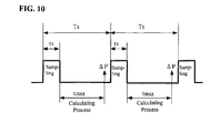
FIG. 10 illustrates the relationship between the sampling period Ts, the sampling interval ts, and the maximum calculating time Tmax. The differential pressure measured value ΔP is obtained for each sampling period Ts, after the sum of the sampling interval ts plus the maximum calculating time Tmax has elapsed. - In the differential pressure transmitting device set forth above, there is a demerit in the sense that the responsiveness will be poorer if the sampling period Ts and the sampling interval ts are long, and the stability of the measured value and the responsiveness have a trade-off relationship. In reality, in applications that require a differential pressure transmitting device there are various requirements for stability of the measured value and for responsiveness, and while some emphasize stability, others emphasize responsiveness.
- Given this, when a differential pressure transmitting device is used in an application wherein responsiveness is emphasized, it is possible to reduce the damping time constant Dτ that is used in the damping calculation in order to achieve acceleration through completing of the damping calculation quickly. However, conventionally because the sampling period Ts and the sampling interval ts have been set on the long side as constant values, it has not been possible to perform thorough improvements when high-speed responsiveness has been required. Because of this, there has been a problem in that it has not been possible to accommodate applications that require high-speed responsiveness, such as fuel control in gas turbine generators.
- The present invention is to resolve problem areas such as set forth above, and the object thereof is to provide a differential pressure transmitting device capable of responding to the need for high-speed responsiveness.
- In order to achieve the object as set forth above, a differential pressure transmitting device comprises: a differential pressure sensor for sensing a pressure differential in a fluid; sampling means for sampling, over a specific sampling interval at each specific sampling period, an electric signal that is in accordance with a pressure differential in the fluid, sensed by the differential pressure sensor; and differential pressure measurement value calculating means for calculating a measurement value for the differential pressure through performing a calculating process that includes at least a first-order delay calculation on the electric signal sampled by the sampling means; including: sampling condition automatic changing means for changing automatically the sampling conditions, with the sampling conditions being the sampling period and/or the sampling interval, so as to be shorter when the speed of the calculating process is faster, based upon parameters that determine the speed of the calculating process.
- Given this, if, when calculating the measurement value for a differential pressure, the parameters that determine the speed of the calculating process change in the direction that makes the speed of the calculating process faster, the sampling period and/or the sampling interval are/is changed automatically so as to be shorter.
- For example, if the parameter for determining the speed of the calculating process when calculating the measurement value for the differential pressure is defined as the damping time constant Dτ, the threshold value for determining that the speed of the calculating process has changed in the direction of being faster is defined as Dτ = 0, and the damping time constant Dτ has changed so that Dτ = 0, then the sampling period Ts is changed automatically from 100 ms to 50 ms and the sampling interval ts is changed automatically from 60 ms to 30 ms.
- Given the present invention, because the sampling period and/or the sampling interval are/is defined as the sampling conditions, and the sampling conditions are changed automatically so as to be shorter when the speed of the calculating process is faster, it is possible to respond to requirements for increased responsiveness by automatically shortening the sampling period and/or the sampling interval when, for example, responsiveness is emphasized and the damping time constant is reduced.
-
-
FIG. 1 is a block diagram illustrating the critical components in one example of embodiment of a differential pressure transmitting device as set forth in the present invention. -
FIG. 2 is a flowchart illustrating one example of the process operations (in the first example of embodiment) in accordance with the sampling condition automatic changing function possessed by a processing device in this differential pressure transmitting device. -
FIG. 3 is a flowchart illustrating another example of the process operations (in a second example of embodiment) in accordance with the sampling condition automatic changing function possessed by a processing device in this differential pressure transmitting device. -
FIG. 4 is a flowchart illustrating another example of the process operations (in a third example of embodiment) in accordance with the sampling condition automatic changing function possessed by a processing device in this differential pressure transmitting device. -
FIG. 5 is a timing chart for explaining the sampling operation when in the standard mode and when in the high-speed mode in the first example of embodiment. -
FIG. 6 is a timing chart for explaining the sampling operation when in the standard mode and when in the high-speed mode in the second example of embodiment. -
FIG. 7 is a timing chart for explaining the sampling operation when in the standard mode and when in the high-speed mode in the third example of embodiment. -
FIG. 8 is a diagram illustrating an example wherein a display portion is provided for displaying, as setting conditions, the damping time constant and the sampling conditions (the sampling period and the sampling interval), used by the processing device. -
FIG. 9 is a block diagram of the functions within the processing device in the differential pressure transmitting device. -
FIG. 10 is a timing chart for explaining the sampling operation in a conventional differential pressure transmitting device. - The present invention will be explained in detail below, based on the drawings.
FIG. 1 is a block diagram illustrating the critical components in one example of embodiment of a differential pressure transmitting device as set forth in the present invention. In thisfigure: 1 is a differential pressure sensor; 2 is an A/D converting device; 3 is a processing device (MPU); 4 is a D/A converting device; and 5 is a damping time constant setting changing unit (damping time constant setting changing means) that enables a change, in accordance with an operation by a user, of the setting for a damping time constant Dτ used in theprocessing device 3. - In this differential
pressure transmitting device 100, thedifferential pressure sensor 1 senses a differential pressure of a fluid, and sends, to the A/D converting device 2, an electric signal (an analog signal) in accordance with this differential pressure. The A/D converting device 2 is in constant operation, receiving the supply of a power supply voltage Vcc, and converts the electric signal that is in accordance with the differential pressure from thedifferential pressure sensor 1 into a digital value. - The
processing device 3 has, as a function that is a feature of the present form of embodiment, a sampling condition automatic changing function, achieved through hardware, comprising a processor, a storage device, and the like, and through a program, which functions cooperatively with the hardware as the processing device to perform a variety of different functions. A specific example of the sampling condition automatic changing function possessed by theprocessing device 3 will be explained below in accordance with the flow charts inFIG. 2, FIG. 3 , andFIG. 4 . - The
processing device 3 periodically checks the damping time constant Dτ that is currently set (FIG. 2 : Step S101). If the damping time constant Dτ is Dτ ≠ 0 (Step S101: NO), then the sampling mode is set to the standard mode (Step S102), and the sampling period Ts is set to Ts = 100 ms (Step S103). - In contrast, if the damping time constant Dτ is Dτ= 0 (Step S101: YES), then the sampling mode is set to the high-speed mode (Step S104), and the sampling period Ts is set to Ts = 50 ms (Step S105).
- Note that in the first example of embodiment, the sampling interval ts is always a constant value (for example, at ts = 30 ms) regardless of the damping time constant Dτ. That is, even if the damping time constant Dτ is changed, the sampling interval ts is maintained at ts = 30 ms.
- If the damping time constant Dτ is Dτ ≠ 0, so that the standard mode is set, then the
processing device 3 samples, for a sampling interval ts = 30 ms for each sampling period Ts = 100 ms, the electric signal that has been converted into a digital value by the A/D converting device 2, and performs a variety of calculating processes, such as a smoothing calculation, a square root calculation, or the like, on the sampled electric signal to calculate a measured value ΔP for the differential pressure, and then outputs this calculated measured value ΔP for the differential pressure through the D/A converting device 4. (SeeFIG. 5 (a) .) In this calculating process, theprocessing device 3 performs the damping operation using the damping time constant Dτ. - If the damping time constant Dτ is changed to Dτ= 0 through an operation by a user from the damping time constant setting changing
unit 5, then theprocessing device 3 changes the sampling mode from standard mode to high-speed mode. In this case, theprocessing device 3 samples, for a sampling interval ts = 30 ms for each sampling period Ts = 50 ms, the electric signal that has been converted into a digital value by the A/D converting device 2, and performs a variety of calculating processes, such as a smoothing calculation, a square root calculation, or the like, on the sampled electric signal to calculate a measured value ΔP for the differential pressure, and then outputs this calculated measured value ΔP for the differential pressure through the D/A converting device 4. (SeeFIG. 5 (b) .) In this calculating process, theprocessing device 3 does not perform the damping calculations. -
FIG. 5 (c) illustrates a timing chart for the case wherein, when the damping time constant Dτ changes so that Dτ = 0, the sampling period Ts is maintained at Ts = 100 ms, and only the damping calculation is not performed. - As can be understood from a comparison of
FIG. 5 (b) and FIG. 5 (c) , when the sampling period Ts is changed from 100 ms to 50 ms (FIG. 5 (b) ), then the calculated value ΔP for the differential pressure can be obtained in a short time period, making it possible to respond to demands for high-speed responsiveness. - The
processing device 3 periodically checks the damping time constant D τ that is currently set (FIG. 3 : Step S201). If the damping time constant D τ is D τ ≠ 0 (Step S201: NO), then the sampling mode is set to the standard mode (Step S202), and the sampling interval ts is set to ts = 60 ms (Step S203). - In contrast, if the damping time constant Dτ is Dτ= 0 (Step S201: YES), then the sampling mode is set to the high-speed mode (Step S204), and the sampling interval ts is set to ts = 30 ms (Step S205).
- Note that in the second example of embodiment, the sampling period Ts is always a constant value (for example, and Ts = 100 ms) regardless of the damping time constant Dτ. That is, even if the damping time constant Dτ is changed, the sampling period Ts is maintained at Ts = 100 ms.
- If the damping time constant D τ is D τ ≠ 0, so that the standard mode is set, then the
processing device 3 samples, for a sampling interval ts = 60 ms for each sampling period Ts = 100 ms, the electric signal that has been converted into a digital value by the A/D converting device 2, and performs a variety of calculating processes, such as a smoothing calculation, a square root calculation, or the like, on the sampled electric signal to calculate a measured value ΔP for the differential pressure, and then outputs this calculated measured value ΔP for the differential pressure through the D/A converting device 4. (SeeFIG. 6 (a) .) In this calculating process, theprocessing device 3 performs the damping operation using the damping time constant Dτ. - If the damping time constant D τ is changed to D τ = 0 through an operation by a user from the damping time constant
setting changing unit 5, then theprocessing device 3 changes the sampling mode from standard mode to high-speed mode. In this case, theprocessing device 3 samples, for a sampling interval ts = 30 ms for each sampling period Ts = 100 ms, the electric signal that has been converted into a digital value by the A/D converting device 2, and performs a variety of calculating processes, such as a smoothing calculation, a square root calculation, or the like, on the sampled electric signal to calculate a measured value ΔP for the differential pressure, and then outputs this calculated measured value ΔP for the differential pressure through the D/A converting device 4. (SeeFIG. 6 (b) .) In this calculating process, theprocessing device 3 does not perform the damping calculations. -
FIG. 6 (c) illustrates a timing chart for the case wherein, when the damping time constant Dτ changes so that Dτ = 0, the sampling interval ts is maintained at ts = 60 ms, and only the damping calculation is not performed. - As can be understood from a comparison of
FIG. 6 (b) and FIG. 6 (c) , when the sampling interval ts is changed from 60 ms to 30 ms (FIG. 6 (b) ), and after the beginning of the sampling period Ts, then the calculated value ΔP for the differential pressure can be obtained in a short time period, making it possible to respond to demands for high-speed responsiveness. - The
processing device 3 periodically checks the damping time constant D τ that is currently set (FIG. 4 : Step S301). If the damping time constant D τ is D τ ≠ 0 (Step S301: NO), then the sampling mode is set to the standard mode (Step S302), the sampling period Ts is set to Ts = 100 ms (Step S303), and the sampling interval ts is set to ts = 60 ms (Step S304). - In contrast if the damping time constant Dτ is Dτ= 0 (Step S301: YES), then the sampling mode is set to the high-speed mode (Step S305), the sampling period Ts is set to Ts = 50 ms (Step S306), and the sampling interval ts is set to ts = 30 ms (Step S307).
- If the damping time constant D τ is D τ ≠ 0, so that the standard mode is set, then the
processing device 3 samples, for a sampling interval ts = 60 ms for each sampling period Ts = 100 ms, the electric signal that has been converted into a digital value by the A/D converting device 2, and performs a variety of calculating processes, such as a smoothing calculation, a square root calculation, or the like, on the sampled electric signal to calculate a measured value ΔP for the differential pressure, and then outputs this calculated measured value ΔP for the differential pressure through the D/A converting device 4. (SeeFIG. 7 (a) .) In this calculating process, theprocessing device 3 performs the damping operation using the damping time constant Dτ. - If the damping time constant D τ is changed to D τ = 0 through an operation by a user from the damping time constant
setting changing unit 5, then theprocessing device 3 changes the sampling mode from standard mode to high-speed mode. In this case, theprocessing device 3 samples, for a sampling interval ts = 30 ms for each sampling period Ts = 50 ms, the electric signal that has been converted into a digital value by the A/D converting device 2, and performs a variety of calculating processes, such as a smoothing calculation, a square root calculation, or the like, on the sampled electric signal to calculate a measured value ΔP for the differential pressure, and then outputs this calculated measured value ΔP for the differential pressure through the D/A converting device 4. (SeeFIG. 7 (b) .) In this calculating process, theprocessing device 3 does not perform the damping calculations. -
FIG. 7 (c) illustrates a timing chart for the case wherein, when the damping time constant Dτ changes so that Dτ = 0, the sampling period Ts is maintained at Ts = 100 ms, the sampling interval ts is set to ts = 60 ms, and only the damping calculation is not performed. - As can be understood from a comparison of
FIG. 7 (b) and FIG. 7 (c) , when the sampling period Ts is changed from 100 ms to 50 ms and the sampling interval ts is changed from 60 ms to 30 ms (FIG. 7 (b) ), then the calculated value ΔP for the differential pressure can be obtained in a short time period, making it possible to obtain the measurement value ΔP in a short time after the start of the sampling period Ts, making it possible to respond to demands for high-speed responsiveness. - In the third example of embodiment, both the sampling interval ts and the sampling period Ts are shortened, accelerating the timing with which the measured value ΔP of the differential pressure is calculated, making it possible to achieve a greater acceleration when compared to the standard mode.
- Furthermore, it is possible to achieve the high speed responsiveness without the user being aware of the sampling period in the sampling interval, through changing the sampling period Ts and the sampling interval ts automatically based on the damping time constant Dτ, as in the first through third examples of embodiment set forth above. In addition, because a variety of applications can be handled using a single differential pressure transmitting device, this can contribute greatly to reducing the spare parts inventories of the customers.
- Note that while in the first through third examples of embodiment, set forth above, if the damping time constant Dτ was set to Dτ = 0 then the high-speed mode was set, and the sampling period Ts was changed automatically from 100 ms to 50 ms, and/or the sampling interval ts was changed automatically from 60 ms to 30 ms; however, the threshold value for evaluating the change to the high-speed mode is not limited to Dτ = 0. For example, the threshold value may be set at Dτ = Is, where the damping calculation is performed using the damping time constant Dτ if Dτ ≤ 1s, and the sampling period Ts may be changed automatically from 100 ms to 50 ms and/or the sampling interval ts may be changed automatically from 60 ms to 30 ms in order to handle the requirements for high speed responsiveness.
- Moreover, while in the first through third examples of embodiment set forth above, in the standard mode the sampling period Ts was set to 100 ms and in the high-speed mode the sampling period Ts was set to 50 ms, or in the standard mode the sampling interval ts was set to ts = 60 ms and in the high-speed mode the sampling time Ts was set to 30 ms, there is no limitation, of course, to these particular values for the sampling period Ts and for the sampling interval ts in the standard mode and the high-speed mode.
- Additionally, in the first through third examples of embodiment set forth above, the sampling period Ts and/or the sampling interval ts may be changed by dividing into several regions according to the damping time constant Dτ, so as to increase the number of sampling modes. For example, three different modes may be provided: (1) a high-speed mode (for those applications that particularly emphasize high speed responsiveness of the differential pressure transmitting device), (2) the standard mode (for those applications that wish to eliminate external noises (for example, the noise in commercial power) while maintaining some degree of responsiveness), and (3) the high-stability mode (the low-speed mode: for those applications that emphasize stability in the output of the differential pressure transmitting device, and which suppress instability in the process input in addition to suppressing the external noise of the standard mode), where, if Dτ = 0, then the high-speed mode is set (where the sampling period Ts = 50 ms and the sampling interval ts = 30 ms), if Dτ ≤ 1 second, then the standard mode is set (where the sampling period Ts = 100 ms and the sampling interval ts = 60 ms), and where if Dτ > 1 second, the high stability mode is set (where the sampling period Ts = 200 ms and the sampling interval ts = 120 ms), wherein it is possible to switch the mode depending on the value of the damping time constant Dτ.
- While the circuits will be more complex, adding a function for switching the A/D filter constants (the resistance and capacitance) when inputting the electric signal into the A/
D converting device 2 and switching the D/A filter constants (the resistance and capacitance) when outputting the electric signal from the D/A converting device 4, depending on the value of the damping time constant Dτ enables even greater accelerations and greater increases in stability to be achieved. For example, when Dτ = 0, the sampling period Ts is set to 50 ms, the sampling interval ts is set to 30 ms, and the A/D filter constants and D/A filter constants are reduced. When Dτ >1s, the sampling period Ts is set to 100 ms, the sampling interval ts is set to 60 ms, and the A/D filter constants and D/A filter constants are increased. The addition of such a function makes it possible to achieve further increases in speed and further increases instability. - Additionally, in the first through third examples of embodiment, set forth above, a display unit (setting condition displaying means) 6 may be provided as illustrated in
FIG. 8 , and the damping time constant Dτ used by theprocessing device 3 may be displayed on the display unit 6 as a setting condition for the sampling conditions (the sampling period Ts and the sampling interval ts). Doing so enables the current setting conditions to be known, to be referenced when changing the settings for the damping time constant Dτ and the sampling conditions. - Additionally, while in the first through third examples of embodiment set forth above the damping time constant Dτ was used as a parameter for setting the speed of the calculating process when calculating the measured value for the differential pressure and the sampling period Ts and/or the sampling interval ts were/was changed based on this damping time constant Dτ, instead the parameter for determining the speed for the targeting process when calculating the measured value for the differential pressure is not limited to the damping time constant Dτ. For example, instead the exponents in a polynomial equation for a compensating calculation used in the calculating process when calculating the measured value for the differential pressure may be used as the parameters, and the sampling period Ts and the sampling interval ts may be changed automatically based on the polynomial exponents.
-
FIG. 9 illustrates a block diagram of the functions within theprocessing device 3 of the differentialpressure transmitting device 100 set forth above. In the differentialpressure transmitting device 100, theprocessing device 3 is provided with a sampling unit (sampling means) 3A, a differential pressure measured value calculating unit (differential pressure measured value calculating means) 3B, and a sampling condition automatic changing unit (sampling condition automatic changing means) 3C. Thesampling unit 3A samples, over a sampling interval ts within each sampling period Ts, the electric signal that is in accordance with the pressure differential in the fluid, sensed by thedifferential pressure sensor 1. The differential pressure measuredvalue calculating unit 3B calculates the measured value ΔP for the differential pressure by performing a variety of processes including, at least, a damping calculation, on the electric signal sampled by thesampling unit 3A. The sampling condition automatic changingunit 3C changes, automatically, the sampling period Ts and/or the sampling interval ts in thesampling unit 3A so as to be shorter when the damping time constant Dτ is Dτ = 0, based on the damping time constant Dτ. - The differential pressure transmitting device according to the present invention can be used in a variety of fields as a device for sensing and transmitting the differential pressure of a fluid in, for example, fuel control in a gas turbine generator.
Claims (3)
- A differential pressure transmitting device comprising:a differential pressure sensor sensing a differential pressure in a fluid;a sampling device sampling, over a specific sampling interval at each specific sampling period, an electric signal that is in accordance with the differential pressure of the fluid, sensed by the differential pressure sensor;a differential pressure measured value calculator calculating a measured value for the differential pressure by performing a calculating process including, at least, a first-order delay calculation, on an electric signal sampled by the sampling means; anda sampling condition automatic changer changing automatically a sampling condition,so as to be shorter, when a calculating process speed is to be made faster, based on a parameter that determines the calculating processing speed, with the sampling period and/or the sampling interval as the sampling conditions.
- The differential pressure transmitting device as set forth in Claim 1, wherein:the parameter for determining the speed of the calculating process is defined as a damping time constant used in the first-order delay calculation; further comprising:a damping time constant setting changer configured to change the setting of the damping time constant.
- The differential pressure transmitting device as set forth in Claim 2, further comprising:a setting condition display displaying at least one of the damping time constant and the sampling condition.
Applications Claiming Priority (2)
| Application Number | Priority Date | Filing Date | Title |
|---|---|---|---|
| JP2008020718A JP5330703B2 (en) | 2008-01-31 | 2008-01-31 | Differential pressure transmitter |
| PCT/JP2009/050367 WO2009096224A1 (en) | 2008-01-31 | 2009-01-14 | Differential pressure transmitter |
Publications (3)
| Publication Number | Publication Date |
|---|---|
| EP2239716A1 true EP2239716A1 (en) | 2010-10-13 |
| EP2239716A4 EP2239716A4 (en) | 2014-06-18 |
| EP2239716B1 EP2239716B1 (en) | 2017-11-15 |
Family
ID=40912577
Family Applications (1)
| Application Number | Title | Priority Date | Filing Date |
|---|---|---|---|
| EP09706698.9A Active EP2239716B1 (en) | 2008-01-31 | 2009-01-14 | Differential pressure transmitter |
Country Status (6)
| Country | Link |
|---|---|
| US (1) | US8326550B2 (en) |
| EP (1) | EP2239716B1 (en) |
| JP (1) | JP5330703B2 (en) |
| KR (1) | KR101066509B1 (en) |
| CN (1) | CN101925937B (en) |
| WO (1) | WO2009096224A1 (en) |
Families Citing this family (5)
| Publication number | Priority date | Publication date | Assignee | Title |
|---|---|---|---|---|
| WO2012105423A1 (en) * | 2011-02-04 | 2012-08-09 | 富士電機株式会社 | Battery-powered gas alarm and control device thereof |
| CN102331351B (en) * | 2011-06-14 | 2013-01-02 | 山东电力研究院 | Connection method for differential pressure transmitter special for test |
| US9136886B2 (en) | 2013-03-11 | 2015-09-15 | Rosemount Inc. | Digitally compensated process transmitter with minimal dead time |
| JP6197726B2 (en) * | 2014-03-28 | 2017-09-20 | 横河電機株式会社 | Field device adjustment method, field device adjustment device, and field device |
| JP6507761B2 (en) * | 2015-03-23 | 2019-05-08 | 横河電機株式会社 | Differential pressure measuring device |
Family Cites Families (17)
| Publication number | Priority date | Publication date | Assignee | Title |
|---|---|---|---|---|
| JPS6255705A (en) * | 1985-09-03 | 1987-03-11 | Shimadzu Corp | programmable control device |
| JPS6266705A (en) | 1985-09-18 | 1987-03-26 | Sharp Corp | Converter |
| US4866435A (en) * | 1987-10-16 | 1989-09-12 | Rosemount Inc. | Digital transmitter with variable resolution as a function of speed |
| JPH0288921A (en) | 1988-09-27 | 1990-03-29 | Yamatake Honeywell Co Ltd | Pressure correcting type differential pressure transmitter |
| JP2506772Y2 (en) * | 1990-06-15 | 1996-08-14 | 横河電機株式会社 | Signal transmitter |
| JP2924166B2 (en) * | 1990-11-09 | 1999-07-26 | 横河電機株式会社 | Signal transmitter |
| JPH04195610A (en) * | 1990-11-28 | 1992-07-15 | Shimadzu Corp | process control equipment |
| JPH05113379A (en) * | 1991-10-22 | 1993-05-07 | Shimadzu Corp | Pressure / differential pressure transmitter |
| JPH0619530A (en) * | 1992-07-02 | 1994-01-28 | Hitachi Ltd | Digital controller |
| JP3223501B2 (en) * | 1996-06-17 | 2001-10-29 | 横河電機株式会社 | Differential pressure measuring device |
| US5909188A (en) * | 1997-02-24 | 1999-06-01 | Rosemont Inc. | Process control transmitter with adaptive analog-to-digital converter |
| DE10021644C2 (en) * | 2000-05-04 | 2002-08-01 | Bosch Gmbh Robert | Operating state-dependent switching of a scanning method of a pressure sensor |
| JP3808294B2 (en) * | 2000-08-07 | 2006-08-09 | セイコーインスツル株式会社 | Portable pressure measuring device |
| JP2003083830A (en) * | 2001-09-14 | 2003-03-19 | Yokogawa Electric Corp | Time constant calculation method of differential pressure transmitter and differential pressure transmitter |
| JP2003162790A (en) * | 2001-11-28 | 2003-06-06 | Yamatake Corp | Correction calculation method in two-wire transmitter and two-wire transmitter |
| JP4366652B2 (en) * | 2004-04-23 | 2009-11-18 | 横河電機株式会社 | Transmitter and duplexing method thereof |
| US7770459B2 (en) * | 2007-07-20 | 2010-08-10 | Rosemount Inc. | Differential pressure diagnostic for process fluid pulsations |
-
2008
- 2008-01-31 JP JP2008020718A patent/JP5330703B2/en active Active
-
2009
- 2009-01-14 CN CN2009801033372A patent/CN101925937B/en active Active
- 2009-01-14 US US12/865,450 patent/US8326550B2/en active Active
- 2009-01-14 EP EP09706698.9A patent/EP2239716B1/en active Active
- 2009-01-14 KR KR1020107014587A patent/KR101066509B1/en active Active
- 2009-01-14 WO PCT/JP2009/050367 patent/WO2009096224A1/en not_active Ceased
Also Published As
| Publication number | Publication date |
|---|---|
| KR101066509B1 (en) | 2011-09-21 |
| JP5330703B2 (en) | 2013-10-30 |
| US20110004424A1 (en) | 2011-01-06 |
| CN101925937A (en) | 2010-12-22 |
| EP2239716B1 (en) | 2017-11-15 |
| WO2009096224A1 (en) | 2009-08-06 |
| US8326550B2 (en) | 2012-12-04 |
| KR20100094549A (en) | 2010-08-26 |
| JP2009180643A (en) | 2009-08-13 |
| CN101925937B (en) | 2012-11-21 |
| EP2239716A4 (en) | 2014-06-18 |
Similar Documents
| Publication | Publication Date | Title |
|---|---|---|
| EP2239716B1 (en) | Differential pressure transmitter | |
| CA2535163A1 (en) | A method and apparatus for correcting output information of flow measurement apparatus | |
| JP2007256231A (en) | Pressure guiding tube clogging detection apparatus and pressure guiding tube clogging detection method | |
| US9823149B2 (en) | Slew rate detection circuit | |
| JP5332306B2 (en) | Method and apparatus for detecting load inflection point in press process | |
| CN101925936B (en) | Testing Equipment | |
| JP2009017681A (en) | Frequency change rate protection relay device | |
| CN106662463B (en) | Detection method and device of sensor background noise | |
| US12196597B2 (en) | Method for operating a flowmeter and flowmeter | |
| JP6484131B2 (en) | Flow measuring device | |
| EP3057344B1 (en) | Sound field measurement device, sound field measurement method, and sound field measurement program | |
| US9898193B2 (en) | Application-specific integrated circuit and measurement transmitter having such a circuit | |
| JP7190639B2 (en) | Arithmetic device, indicator, temperature controller, and method | |
| US11536742B2 (en) | Method for operating a micromechanical inertial sensor | |
| CN105987787A (en) | Correction device, correction method, program, and electrostatic capacitance type pressure sensor | |
| KR20040020353A (en) | Vacumm Ion Pump Controller based on Software and Microprocessor and Measuring Method of Vacumm Using the same | |
| JP2005315789A (en) | Instrumentation system | |
| JPH0288921A (en) | Pressure correcting type differential pressure transmitter | |
| KR100566134B1 (en) | Portable Pressure Measuring Device | |
| JP2009053077A (en) | Load measurement device and error correction method therefor | |
| JP2009103588A (en) | Field device, abnormality diagnosis system and abnormality diagnosis method | |
| JPH11118651A (en) | Digital pressure gauge | |
| TW201408997A (en) | Method for determining altitude and altitude meter using the method | |
| JP2014085164A (en) | Dissolved gas amount measuring apparatus and liquid compressibility ratio measuring apparatus |
Legal Events
| Date | Code | Title | Description |
|---|---|---|---|
| PUAI | Public reference made under article 153(3) epc to a published international application that has entered the european phase |
Free format text: ORIGINAL CODE: 0009012 |
|
| 17P | Request for examination filed |
Effective date: 20100729 |
|
| AK | Designated contracting states |
Kind code of ref document: A1 Designated state(s): AT BE BG CH CY CZ DE DK EE ES FI FR GB GR HR HU IE IS IT LI LT LU LV MC MK MT NL NO PL PT RO SE SI SK TR |
|
| AX | Request for extension of the european patent |
Extension state: AL BA RS |
|
| DAX | Request for extension of the european patent (deleted) | ||
| RAP1 | Party data changed (applicant data changed or rights of an application transferred) |
Owner name: AZBIL CORPORATION |
|
| A4 | Supplementary search report drawn up and despatched |
Effective date: 20140520 |
|
| RIC1 | Information provided on ipc code assigned before grant |
Ipc: G01L 19/00 20060101ALI20140514BHEP Ipc: G08C 13/00 20060101AFI20140514BHEP Ipc: G01L 13/00 20060101ALI20140514BHEP |
|
| GRAP | Despatch of communication of intention to grant a patent |
Free format text: ORIGINAL CODE: EPIDOSNIGR1 |
|
| STAA | Information on the status of an ep patent application or granted ep patent |
Free format text: STATUS: GRANT OF PATENT IS INTENDED |
|
| INTG | Intention to grant announced |
Effective date: 20170607 |
|
| GRAS | Grant fee paid |
Free format text: ORIGINAL CODE: EPIDOSNIGR3 |
|
| GRAA | (expected) grant |
Free format text: ORIGINAL CODE: 0009210 |
|
| STAA | Information on the status of an ep patent application or granted ep patent |
Free format text: STATUS: THE PATENT HAS BEEN GRANTED |
|
| AK | Designated contracting states |
Kind code of ref document: B1 Designated state(s): AT BE BG CH CY CZ DE DK EE ES FI FR GB GR HR HU IE IS IT LI LT LU LV MC MK MT NL NO PL PT RO SE SI SK TR |
|
| REG | Reference to a national code |
Ref country code: CH Ref legal event code: EP Ref country code: GB Ref legal event code: FG4D Ref country code: AT Ref legal event code: REF Ref document number: 946977 Country of ref document: AT Kind code of ref document: T Effective date: 20171115 |
|
| REG | Reference to a national code |
Ref country code: IE Ref legal event code: FG4D |
|
| REG | Reference to a national code |
Ref country code: DE Ref legal event code: R096 Ref document number: 602009049355 Country of ref document: DE |
|
| REG | Reference to a national code |
Ref country code: NL Ref legal event code: MP Effective date: 20171115 |
|
| REG | Reference to a national code |
Ref country code: LT Ref legal event code: MG4D |
|
| REG | Reference to a national code |
Ref country code: AT Ref legal event code: MK05 Ref document number: 946977 Country of ref document: AT Kind code of ref document: T Effective date: 20171115 |
|
| PG25 | Lapsed in a contracting state [announced via postgrant information from national office to epo] |
Ref country code: NL Free format text: LAPSE BECAUSE OF FAILURE TO SUBMIT A TRANSLATION OF THE DESCRIPTION OR TO PAY THE FEE WITHIN THE PRESCRIBED TIME-LIMIT Effective date: 20171115 Ref country code: FI Free format text: LAPSE BECAUSE OF FAILURE TO SUBMIT A TRANSLATION OF THE DESCRIPTION OR TO PAY THE FEE WITHIN THE PRESCRIBED TIME-LIMIT Effective date: 20171115 Ref country code: ES Free format text: LAPSE BECAUSE OF FAILURE TO SUBMIT A TRANSLATION OF THE DESCRIPTION OR TO PAY THE FEE WITHIN THE PRESCRIBED TIME-LIMIT Effective date: 20171115 Ref country code: LT Free format text: LAPSE BECAUSE OF FAILURE TO SUBMIT A TRANSLATION OF THE DESCRIPTION OR TO PAY THE FEE WITHIN THE PRESCRIBED TIME-LIMIT Effective date: 20171115 Ref country code: NO Free format text: LAPSE BECAUSE OF FAILURE TO SUBMIT A TRANSLATION OF THE DESCRIPTION OR TO PAY THE FEE WITHIN THE PRESCRIBED TIME-LIMIT Effective date: 20180215 Ref country code: SE Free format text: LAPSE BECAUSE OF FAILURE TO SUBMIT A TRANSLATION OF THE DESCRIPTION OR TO PAY THE FEE WITHIN THE PRESCRIBED TIME-LIMIT Effective date: 20171115 |
|
| PG25 | Lapsed in a contracting state [announced via postgrant information from national office to epo] |
Ref country code: GR Free format text: LAPSE BECAUSE OF FAILURE TO SUBMIT A TRANSLATION OF THE DESCRIPTION OR TO PAY THE FEE WITHIN THE PRESCRIBED TIME-LIMIT Effective date: 20180216 Ref country code: BG Free format text: LAPSE BECAUSE OF FAILURE TO SUBMIT A TRANSLATION OF THE DESCRIPTION OR TO PAY THE FEE WITHIN THE PRESCRIBED TIME-LIMIT Effective date: 20180215 Ref country code: HR Free format text: LAPSE BECAUSE OF FAILURE TO SUBMIT A TRANSLATION OF THE DESCRIPTION OR TO PAY THE FEE WITHIN THE PRESCRIBED TIME-LIMIT Effective date: 20171115 Ref country code: AT Free format text: LAPSE BECAUSE OF FAILURE TO SUBMIT A TRANSLATION OF THE DESCRIPTION OR TO PAY THE FEE WITHIN THE PRESCRIBED TIME-LIMIT Effective date: 20171115 Ref country code: LV Free format text: LAPSE BECAUSE OF FAILURE TO SUBMIT A TRANSLATION OF THE DESCRIPTION OR TO PAY THE FEE WITHIN THE PRESCRIBED TIME-LIMIT Effective date: 20171115 |
|
| PG25 | Lapsed in a contracting state [announced via postgrant information from national office to epo] |
Ref country code: CZ Free format text: LAPSE BECAUSE OF FAILURE TO SUBMIT A TRANSLATION OF THE DESCRIPTION OR TO PAY THE FEE WITHIN THE PRESCRIBED TIME-LIMIT Effective date: 20171115 Ref country code: SK Free format text: LAPSE BECAUSE OF FAILURE TO SUBMIT A TRANSLATION OF THE DESCRIPTION OR TO PAY THE FEE WITHIN THE PRESCRIBED TIME-LIMIT Effective date: 20171115 Ref country code: CY Free format text: LAPSE BECAUSE OF FAILURE TO SUBMIT A TRANSLATION OF THE DESCRIPTION OR TO PAY THE FEE WITHIN THE PRESCRIBED TIME-LIMIT Effective date: 20171115 Ref country code: DK Free format text: LAPSE BECAUSE OF FAILURE TO SUBMIT A TRANSLATION OF THE DESCRIPTION OR TO PAY THE FEE WITHIN THE PRESCRIBED TIME-LIMIT Effective date: 20171115 Ref country code: EE Free format text: LAPSE BECAUSE OF FAILURE TO SUBMIT A TRANSLATION OF THE DESCRIPTION OR TO PAY THE FEE WITHIN THE PRESCRIBED TIME-LIMIT Effective date: 20171115 |
|
| REG | Reference to a national code |
Ref country code: DE Ref legal event code: R097 Ref document number: 602009049355 Country of ref document: DE |
|
| PG25 | Lapsed in a contracting state [announced via postgrant information from national office to epo] |
Ref country code: IT Free format text: LAPSE BECAUSE OF FAILURE TO SUBMIT A TRANSLATION OF THE DESCRIPTION OR TO PAY THE FEE WITHIN THE PRESCRIBED TIME-LIMIT Effective date: 20171115 Ref country code: RO Free format text: LAPSE BECAUSE OF FAILURE TO SUBMIT A TRANSLATION OF THE DESCRIPTION OR TO PAY THE FEE WITHIN THE PRESCRIBED TIME-LIMIT Effective date: 20171115 Ref country code: PL Free format text: LAPSE BECAUSE OF FAILURE TO SUBMIT A TRANSLATION OF THE DESCRIPTION OR TO PAY THE FEE WITHIN THE PRESCRIBED TIME-LIMIT Effective date: 20171115 |
|
| REG | Reference to a national code |
Ref country code: CH Ref legal event code: PL |
|
| PLBE | No opposition filed within time limit |
Free format text: ORIGINAL CODE: 0009261 |
|
| STAA | Information on the status of an ep patent application or granted ep patent |
Free format text: STATUS: NO OPPOSITION FILED WITHIN TIME LIMIT |
|
| 26N | No opposition filed |
Effective date: 20180817 |
|
| GBPC | Gb: european patent ceased through non-payment of renewal fee |
Effective date: 20180215 |
|
| PG25 | Lapsed in a contracting state [announced via postgrant information from national office to epo] |
Ref country code: FR Free format text: LAPSE BECAUSE OF NON-PAYMENT OF DUE FEES Effective date: 20180131 Ref country code: LU Free format text: LAPSE BECAUSE OF NON-PAYMENT OF DUE FEES Effective date: 20180114 |
|
| REG | Reference to a national code |
Ref country code: IE Ref legal event code: MM4A |
|
| REG | Reference to a national code |
Ref country code: FR Ref legal event code: ST Effective date: 20180928 |
|
| REG | Reference to a national code |
Ref country code: BE Ref legal event code: MM Effective date: 20180131 |
|
| PG25 | Lapsed in a contracting state [announced via postgrant information from national office to epo] |
Ref country code: CH Free format text: LAPSE BECAUSE OF NON-PAYMENT OF DUE FEES Effective date: 20180131 Ref country code: SI Free format text: LAPSE BECAUSE OF FAILURE TO SUBMIT A TRANSLATION OF THE DESCRIPTION OR TO PAY THE FEE WITHIN THE PRESCRIBED TIME-LIMIT Effective date: 20171115 Ref country code: BE Free format text: LAPSE BECAUSE OF NON-PAYMENT OF DUE FEES Effective date: 20180131 Ref country code: LI Free format text: LAPSE BECAUSE OF NON-PAYMENT OF DUE FEES Effective date: 20180131 |
|
| PG25 | Lapsed in a contracting state [announced via postgrant information from national office to epo] |
Ref country code: IE Free format text: LAPSE BECAUSE OF NON-PAYMENT OF DUE FEES Effective date: 20180114 |
|
| PG25 | Lapsed in a contracting state [announced via postgrant information from national office to epo] |
Ref country code: GB Free format text: LAPSE BECAUSE OF NON-PAYMENT OF DUE FEES Effective date: 20180215 |
|
| PG25 | Lapsed in a contracting state [announced via postgrant information from national office to epo] |
Ref country code: MC Free format text: LAPSE BECAUSE OF FAILURE TO SUBMIT A TRANSLATION OF THE DESCRIPTION OR TO PAY THE FEE WITHIN THE PRESCRIBED TIME-LIMIT Effective date: 20171115 |
|
| PG25 | Lapsed in a contracting state [announced via postgrant information from national office to epo] |
Ref country code: MT Free format text: LAPSE BECAUSE OF NON-PAYMENT OF DUE FEES Effective date: 20180114 |
|
| PG25 | Lapsed in a contracting state [announced via postgrant information from national office to epo] |
Ref country code: TR Free format text: LAPSE BECAUSE OF FAILURE TO SUBMIT A TRANSLATION OF THE DESCRIPTION OR TO PAY THE FEE WITHIN THE PRESCRIBED TIME-LIMIT Effective date: 20171115 |
|
| PG25 | Lapsed in a contracting state [announced via postgrant information from national office to epo] |
Ref country code: PT Free format text: LAPSE BECAUSE OF FAILURE TO SUBMIT A TRANSLATION OF THE DESCRIPTION OR TO PAY THE FEE WITHIN THE PRESCRIBED TIME-LIMIT Effective date: 20171115 Ref country code: HU Free format text: LAPSE BECAUSE OF FAILURE TO SUBMIT A TRANSLATION OF THE DESCRIPTION OR TO PAY THE FEE WITHIN THE PRESCRIBED TIME-LIMIT; INVALID AB INITIO Effective date: 20090114 |
|
| PG25 | Lapsed in a contracting state [announced via postgrant information from national office to epo] |
Ref country code: MK Free format text: LAPSE BECAUSE OF NON-PAYMENT OF DUE FEES Effective date: 20171115 |
|
| PG25 | Lapsed in a contracting state [announced via postgrant information from national office to epo] |
Ref country code: IS Free format text: LAPSE BECAUSE OF FAILURE TO SUBMIT A TRANSLATION OF THE DESCRIPTION OR TO PAY THE FEE WITHIN THE PRESCRIBED TIME-LIMIT Effective date: 20180315 |
|
| PGFP | Annual fee paid to national office [announced via postgrant information from national office to epo] |
Ref country code: DE Payment date: 20241203 Year of fee payment: 17 |