EP2239585B1 - Flüssigkeitssammel- und messsystem - Google Patents
Flüssigkeitssammel- und messsystem Download PDFInfo
- Publication number
- EP2239585B1 EP2239585B1 EP08703647.1A EP08703647A EP2239585B1 EP 2239585 B1 EP2239585 B1 EP 2239585B1 EP 08703647 A EP08703647 A EP 08703647A EP 2239585 B1 EP2239585 B1 EP 2239585B1
- Authority
- EP
- European Patent Office
- Prior art keywords
- blood
- liquid
- information
- volume
- radiation
- Prior art date
- Legal status (The legal status is an assumption and is not a legal conclusion. Google has not performed a legal analysis and makes no representation as to the accuracy of the status listed.)
- Not-in-force
Links
Images


Classifications
-
- G—PHYSICS
- G01—MEASURING; TESTING
- G01F—MEASURING VOLUME, VOLUME FLOW, MASS FLOW OR LIQUID LEVEL; METERING BY VOLUME
- G01F3/00—Measuring the volume flow of fluids or fluent solid material wherein the fluid passes through the meter in successive and more or less isolated quantities, the meter being driven by the flow
- G01F3/36—Measuring the volume flow of fluids or fluent solid material wherein the fluid passes through the meter in successive and more or less isolated quantities, the meter being driven by the flow with stationary measuring chambers having constant volume during measurement
- G01F3/38—Measuring the volume flow of fluids or fluent solid material wherein the fluid passes through the meter in successive and more or less isolated quantities, the meter being driven by the flow with stationary measuring chambers having constant volume during measurement having only one measuring chamber
-
- A—HUMAN NECESSITIES
- A61—MEDICAL OR VETERINARY SCIENCE; HYGIENE
- A61B—DIAGNOSIS; SURGERY; IDENTIFICATION
- A61B5/00—Measuring for diagnostic purposes; Identification of persons
- A61B5/145—Measuring characteristics of blood in vivo, e.g. gas concentration, pH value; Measuring characteristics of body fluids or tissues, e.g. interstitial fluid, cerebral tissue
- A61B5/14503—Measuring characteristics of blood in vivo, e.g. gas concentration, pH value; Measuring characteristics of body fluids or tissues, e.g. interstitial fluid, cerebral tissue invasive, e.g. introduced into the body by a catheter or needle or using implanted sensors
-
- A—HUMAN NECESSITIES
- A61—MEDICAL OR VETERINARY SCIENCE; HYGIENE
- A61B—DIAGNOSIS; SURGERY; IDENTIFICATION
- A61B5/00—Measuring for diagnostic purposes; Identification of persons
- A61B5/145—Measuring characteristics of blood in vivo, e.g. gas concentration, pH value; Measuring characteristics of body fluids or tissues, e.g. interstitial fluid, cerebral tissue
- A61B5/14546—Measuring characteristics of blood in vivo, e.g. gas concentration, pH value; Measuring characteristics of body fluids or tissues, e.g. interstitial fluid, cerebral tissue for measuring analytes not otherwise provided for, e.g. ions, cytochromes
-
- A—HUMAN NECESSITIES
- A61—MEDICAL OR VETERINARY SCIENCE; HYGIENE
- A61B—DIAGNOSIS; SURGERY; IDENTIFICATION
- A61B5/00—Measuring for diagnostic purposes; Identification of persons
- A61B5/15—Devices for taking samples of blood
- A61B5/150007—Details
- A61B5/150015—Source of blood
- A61B5/15003—Source of blood for venous or arterial blood
-
- A—HUMAN NECESSITIES
- A61—MEDICAL OR VETERINARY SCIENCE; HYGIENE
- A61B—DIAGNOSIS; SURGERY; IDENTIFICATION
- A61B5/00—Measuring for diagnostic purposes; Identification of persons
- A61B5/15—Devices for taking samples of blood
- A61B5/150007—Details
- A61B5/150206—Construction or design features not otherwise provided for; manufacturing or production; packages; sterilisation of piercing element, piercing device or sampling device
- A61B5/150229—Pumps for assisting the blood sampling
-
- A—HUMAN NECESSITIES
- A61—MEDICAL OR VETERINARY SCIENCE; HYGIENE
- A61B—DIAGNOSIS; SURGERY; IDENTIFICATION
- A61B5/00—Measuring for diagnostic purposes; Identification of persons
- A61B5/15—Devices for taking samples of blood
- A61B5/150007—Details
- A61B5/150755—Blood sample preparation for further analysis, e.g. by separating blood components or by mixing
-
- A—HUMAN NECESSITIES
- A61—MEDICAL OR VETERINARY SCIENCE; HYGIENE
- A61B—DIAGNOSIS; SURGERY; IDENTIFICATION
- A61B5/00—Measuring for diagnostic purposes; Identification of persons
- A61B5/15—Devices for taking samples of blood
- A61B5/150007—Details
- A61B5/150946—Means for varying, regulating, indicating or limiting the speed or time of blood collection
-
- A—HUMAN NECESSITIES
- A61—MEDICAL OR VETERINARY SCIENCE; HYGIENE
- A61B—DIAGNOSIS; SURGERY; IDENTIFICATION
- A61B5/00—Measuring for diagnostic purposes; Identification of persons
- A61B5/15—Devices for taking samples of blood
- A61B5/150992—Blood sampling from a fluid line external to a patient, such as a catheter line, combined with an infusion line; blood sampling from indwelling needle sets, e.g. sealable ports, luer couplings, valves
-
- A—HUMAN NECESSITIES
- A61—MEDICAL OR VETERINARY SCIENCE; HYGIENE
- A61B—DIAGNOSIS; SURGERY; IDENTIFICATION
- A61B5/00—Measuring for diagnostic purposes; Identification of persons
- A61B5/15—Devices for taking samples of blood
- A61B5/153—Devices specially adapted for taking samples of venous or arterial blood, e.g. with syringes
-
- A—HUMAN NECESSITIES
- A61—MEDICAL OR VETERINARY SCIENCE; HYGIENE
- A61B—DIAGNOSIS; SURGERY; IDENTIFICATION
- A61B5/00—Measuring for diagnostic purposes; Identification of persons
- A61B5/15—Devices for taking samples of blood
- A61B5/155—Devices specially adapted for continuous or multiple sampling, e.g. at predetermined intervals
-
- A—HUMAN NECESSITIES
- A61—MEDICAL OR VETERINARY SCIENCE; HYGIENE
- A61B—DIAGNOSIS; SURGERY; IDENTIFICATION
- A61B5/00—Measuring for diagnostic purposes; Identification of persons
- A61B5/15—Devices for taking samples of blood
- A61B5/157—Devices characterised by integrated means for measuring characteristics of blood
-
- G—PHYSICS
- G01—MEASURING; TESTING
- G01F—MEASURING VOLUME, VOLUME FLOW, MASS FLOW OR LIQUID LEVEL; METERING BY VOLUME
- G01F13/00—Apparatus for measuring by volume and delivering fluids or fluent solid materials, not provided for in the preceding groups
-
- G—PHYSICS
- G01—MEASURING; TESTING
- G01F—MEASURING VOLUME, VOLUME FLOW, MASS FLOW OR LIQUID LEVEL; METERING BY VOLUME
- G01F13/00—Apparatus for measuring by volume and delivering fluids or fluent solid materials, not provided for in the preceding groups
- G01F13/006—Apparatus for measuring by volume and delivering fluids or fluent solid materials, not provided for in the preceding groups measuring volume in function of time
-
- A—HUMAN NECESSITIES
- A61—MEDICAL OR VETERINARY SCIENCE; HYGIENE
- A61B—DIAGNOSIS; SURGERY; IDENTIFICATION
- A61B2503/00—Evaluating a particular growth phase or type of persons or animals
- A61B2503/40—Animals
-
- G—PHYSICS
- G01—MEASURING; TESTING
- G01N—INVESTIGATING OR ANALYSING MATERIALS BY DETERMINING THEIR CHEMICAL OR PHYSICAL PROPERTIES
- G01N21/00—Investigating or analysing materials by the use of optical means, i.e. using sub-millimetre waves, infrared, visible or ultraviolet light
- G01N21/01—Arrangements or apparatus for facilitating the optical investigation
- G01N21/03—Cuvette constructions
- G01N21/07—Centrifugal type cuvettes
-
- G—PHYSICS
- G01—MEASURING; TESTING
- G01N—INVESTIGATING OR ANALYSING MATERIALS BY DETERMINING THEIR CHEMICAL OR PHYSICAL PROPERTIES
- G01N21/00—Investigating or analysing materials by the use of optical means, i.e. using sub-millimetre waves, infrared, visible or ultraviolet light
- G01N21/62—Systems in which the material investigated is excited whereby it emits light or causes a change in wavelength of the incident light
- G01N21/63—Systems in which the material investigated is excited whereby it emits light or causes a change in wavelength of the incident light optically excited
- G01N21/64—Fluorescence; Phosphorescence
- G01N21/6428—Measuring fluorescence of fluorescent products of reactions or of fluorochrome labelled reactive substances, e.g. measuring quenching effects, using measuring "optrodes"
-
- G—PHYSICS
- G01—MEASURING; TESTING
- G01N—INVESTIGATING OR ANALYSING MATERIALS BY DETERMINING THEIR CHEMICAL OR PHYSICAL PROPERTIES
- G01N21/00—Investigating or analysing materials by the use of optical means, i.e. using sub-millimetre waves, infrared, visible or ultraviolet light
- G01N21/62—Systems in which the material investigated is excited whereby it emits light or causes a change in wavelength of the incident light
- G01N21/63—Systems in which the material investigated is excited whereby it emits light or causes a change in wavelength of the incident light optically excited
- G01N21/64—Fluorescence; Phosphorescence
- G01N21/645—Specially adapted constructive features of fluorimeters
Definitions
- This invention relates to a liquid collecting and measuring system having a liquid collecting apparatus for collecting a liquid to be measured, as separated in a time series, and a measuring apparatus for measuring light generating from a luminescent or fluorescent substance included in the collected liquid, or radiation included in the liquid.
- the liquid collecting apparatus will be described taking a blood collecting apparatus which collects blood, for example.
- the measuring apparatus will be described taking, for example, an apparatus for counting radiation included in the blood and measuring count information such as a count of the radiation or radioactive concentration.
- These apparatus are used for quantitative analyses In nuclear medicine diagnosis (e.g. PET (Positron Emission Tomography), SPECT (Single Photon Emission CT) and so on), and are used especially for measurement of a radioactive concentration in arterial blood of small animals (e.g. mice, rats and so on).
- nuclear medicine diagnosis e.g. PET (Positron Emission Tomography), SPECT (Single Photon Emission CT) and so on
- small animals e.g. mice, rats and so on.
- the following modes (a) - (c) are employed in the quantitative analysis of the above small animals:
- Blood delivering itself under blood pressure from the other end of a catheter inserted into a mouse artery is received in a suitable receptacle. Then, a fixed volume of the blood in the receptacle is sucked up with a volumetric pipette, and a radioactive concentration in whole blood is measured by calculating (i.e. counting) radiation in the sucked-up blood. Further, plasma is obtained by centrifugal separation of the blood remaining in the receptacle, which is similarly collected with a volumetric pipette to measure a radioactive concentration in plasma.
- a ⁇ + ray detector is installed in an arterial blood channel to measure a radioactive concentration in blood.
- ⁇ + rays are detected with a plastic scintillator or PIN diode.
- a diode has a long and thin shape with a length of 30 [mm], and a detectable area is increased by installing a tube containing blood along the direction of a long side, thereby to secure detection efficiency.
- the microchip MC has, arranged thereon, one main flow path F M , selectable branch flow paths F B , and side flow paths F N for feeding a heparin solution H used for flow path cleaning or blood discharging, and for draining used heparin solution H and blood B.
- a receptacle is placed at the end of each branch flow path F B , and one of the branch flow paths F B is selected by a gas pressure of argon gas Gas supplied to the microchip MC or a mechanism of the microchip MC. With one of the branch flow paths F B selected, blood B is poured in.
- Each of the flow paths F M and F B is formed by grooving the microchip MC in a predetermined size. It is the characteristic of the microchip MC that a minute volume of blood B is specified if a groove length or a groove area of the poured-in blood B is known. With the blood B of a predetermined volume filling the flow paths, based on the specified minute volume, the blood B sent into a predetermined receptacle (not shown) by feeding the heparin solution H under pressure. Subsequently, each of the flow paths F M and F B is cleaned with the heparin solution H to be ready for a next blood collection. The blood B in the receptacle is sucked up along with physiological saline into another receptacle, and the radiation in the blood B is counted with a well counter (see Nonpatent Document 2, for example).
- a liquid collecting and measuring system comprising the features of the preamble of claim 1 is known from US 2008/003668 A1 .
- WO 97/16713 relates to a process and a device for determining rheological and mechanical characteristics of materials, wherein the device operates as an automatic analyzer for simultaneous measurement of various material characfieristics.
- the basic principle consists in using variable accelerated forces and registering the changes effected in the test matrial.
- US 2002/0012117 A1 discloses an apparatus for timing intermittent illumination of a sample tube positioned on a centrifuge platen.
- the apparatus is configured for measuring light generating from a fluorescent substance included in a liquid to be measured and for obtaining information on the light.
- US 3,679,367 relates to an apparatus for determining the pack volume of particulates in liquid mixtures, wherein blood samples are successively and centrifugally loaded into a same capillary chamber defined in a continuously rotating centrifuge head to measure the respective packed cell volumes, and the capillary chamber is open-ended and has a serpentine configuration.
- the modes (a) - (c) above have a problem with the volume of collected blood and frequency of blood collection, and a problem that it is impossible to determine accurately a hematocrit value or a radioactive concentration in blood which is count information per unit volume. Even if a minute volume of blood is specified in the mode (c), radioactivity will attenuate during the transfer to another receptacle. There is a possibility that statistical precision of the hematocrit value and the radioactive concentration in plasma which is count information per unit volume will lower as with the latter problem. The former problem will be described in detail below.
- the body weight of a mouse is assumed to be 30 [g]. Since roughly 7.5% of the weight is blood, the total blood volume assumed is 2250 [ ⁇ L]. With a loss up to about 10% of the total blood volume, the influence on the physiological condition of the mouse can be disregarded, and thus a permissible maximum volume of collected blood is 225 [ ⁇ L].
- the mode (a) above is a mode in which blood is once taken out in an amount corresponding at least to the specified volume, and the specified volume is sucked up therefrom. This results in a loss of a large amount of blood. Therefore, the sampling number (the number of blood samples) obtained within the permissible maximum volume of collected blood is small, and a quantitative analysis cannot be conducted fully.
- the mode (b) above continues pouring blood into the above-noted tube at a fixed flow rate (e.g. at least 8 [ ⁇ L/min] with the condition that no coagulation takes place). Therefore, measurement time is restricted in order to be less than the permissible maximum volume of collected blood, and a prolonged quantitative analysis cannot be conducted.
- the mode (c) above realizes a constant volume by filling up the entire flow paths on the microchip with blood, and inhibits contamination between different times of blood collection by cleaning the entire flow paths with the heparin solution for every blood collection. Therefore, the blood that remains in locations other than constant volume portions of the minute flow rate chip is wasted at every blood collection, which increases the total amount of collected blood. Particularly, blood remaining in unused spaces such as connections to the chip is wasted at every blood collection, which is considered to increase the total amount of collected blood with every blood collection.
- the mode (a) above is a mode in which blood is once taken out in an amount corresponding at least to the specified volume, and the specified volume is sucked up therefrom, as noted hereinbefore. Therefore, high frequency measurement is procedurally difficult.
- a catheter used in withdrawing blood is very thin and considering also the viscosity of blood, a very high speed cannot be expected in dripping blood from the tip end of the catheter toward a syringe for sample holding, either. Based on the above, high frequency blood collection is impossible with the mode (a).
- the mode (c) above once fills the blood flow paths with blood, and washes it out with a heparin solution. Since the entire flow paths on the chip (device) are filled with blood for every blood collection, the entire flow paths need to be cleaned with the heparin solution before moving on to a next blood collection as noted above. Therefore, blood or the heparin solution needs to be filled into the flow paths successively for every blood collection, which may consume time, and this is unsuitable to high-frequency blood collection.
- This invention has been made having regard to the state of the art noted above, and its object is to provide a liquid collecting and measuring system having a liquid collecting apparatus and a measuring apparatus, which can reduce the amount of liquid collected, secure the frequency of collection, and accurately obtain information on light or radiation per unit volume.
- the object is solved by the liquid collecting and measuring system according to claim 1.
- a measuring apparatus for measuring light generating from a luminescent or fluorescent substance included in a liquid to be measured or radiation included in the liquid to be measured, comprising (A) a detecting device for simultaneously detecting the light or the radiation in two dimensions to obtain two-dimensional image information on the light or the radiation, and (B) an information calculating device for obtaining information on the light or the radiation per unit volume based on a volume of the liquid determined from image information on a flat plate storing the liquid and having a plurality of grooves and information on the grooves grooved in the flat plate, and the two-dimensional image information on the light or the radiation obtained by the detecting device.
- the measuring apparatus of the aspect includes (A) a detecting device and (B) an information calculating device. Based on a volume of the liquid determined from image information on the flat plate storing the liquid and having a plurality of grooves and information on the grooves grooved in the flat plate, and two-dimensional image information on light or radiation obtained by the detecting device, the information calculating device obtains information on the light or radiation per unit volume. That is, as for the liquid already transferred to the flat plate, no variation such as a subsequent decrease occurs with the volume of the liquid derived from the image information on the flat plate and the information on the grooves grooved in the flat plate, and based on the volume of the liquid, the information on the light or radiation per unit volume is obtained.
- the detecting device can reduce the influence of photobleaching of light or attenuation of radiation by carrying out simultaneous detection in two dimensions.
- the liquid to be measured is blood
- the detecting device may detect radiation included in the blood.
- the information calculating device can obtain count information on the radiation per unit volume accurately.
- the liquid may be a liquid including a fluorescent agent.
- a fluorescent substance which is a fluorescent agent is included in the liquid.
- the measuring apparatus of this aspect will measure light generating from a luminescent or fluorescent substance, thereby to obtain information on light per unit volume. It is to be noted that "luminescence" as used in this specification includes luminescence and fluorescence.
- the detecting device counts and detects separately, as two-dimensional radiation information, the radiation included in the plasma and blood cell resulting from a plasma separation centrifuging the blood. Based on the volume of each part of the plasma and blood cell and the count information on the radiation of each part obtained by the detecting device, the information calculating device obtains count information on each part per unit volume. It is possible to determine volumes of parts of the plasma and blood cell in parallel, thereby to obtain count information on each part per unit volume in parallel (i.e. to obtain at the same time). This simultaneous calculation can extend detection time (measuring time) by the detecting device, which provides also an advantage that a low-concentration dose of radiation can be measured with high statistical accuracy.
- a liquid collecting and measuring system having a liquid collecting apparatus for collecting a liquid to be measured, and a measuring apparatus for measuring light generating from a luminescent or fluorescent substance included in the liquid collected or radiation included in the liquid, comprising (A) a detecting device for simultaneously detecting the light or the radiation in two dimensions to obtain two-dimensional image information on the light or the radiation, and (B) an information calculating device for obtaining information on the light or the radiation per unit volume based on a volume of the liquid determined from image information on a flat plate storing the liquid and having a plurality of grooves and information on the grooves grooved in the flat plate, and the two-dimensional Image information on the light or the radiation obtained by the detecting device.
- the blood collecting and measuring system of this aspect as with the measuring apparatus of this aspect, as for the liquid already transferred to the flat plate, no variation such as a subsequent decrease occurs with the volume of the liquid derived from the image information on the flat plate and the information on the grooves grooved in the flat plate, and based on the volume of the liquid, the information on light or radiation per unit volume is obtained. Therefore, by using the image information on the flat plate, the information on the light or the radiation per unit volume can be obtained accurately, with no variation in the volume of the liquid.
- the liquid collecting apparatus included in the system is not limited to any construction as long as it collects the liquid to be measured, but preferably includes (a) a flow path and (b) an extracting device. That is, the extracting device inserts a gas or a liquid other than the above-noted liquid to be measured, as separators, at designated predetermined intervals, thereby to take out the liquid to be measured, as separated in a time series.
- the measuring apparatus included in the system measures light generating from a luminescent or fluorescent substance included in the liquid or radiation included in the liquid to be measured.
- the amount of collected liquid can be reduced, and the frequency of collection can be secured.
- the information on light or radiation per unit volume can be obtained accurately.
- the above flow path preferably, is formed of what has been grooved in a predetermined size in a planar substrate. It is also preferred to include (c) an optical measuring device. For application to centrifugal separation of the liquid, (d) a flat plate and (e) a rotating device may be provided.
- the flat plate is the same as the flat plate which stores the liquid (to be measured), and has a plurality of grooves formed in the predetermined size. The plurality of grooves are formed to allow the liquid to be measured to circulate with respect to the flow path, and are formed to extend radially.
- an image pickup device In carrying out such centrifugal separation, (f) an image pickup device, (g) a groove length and groove area calculating device and (h) a volume calculating device may be provided.
- the shade difference of the image corresponds to the image information of the flat plate in the liquid collecting and measuring system.
- the cross-sectional area of the grooves or the depth of the grooves corresponds to the information on the grooves in the liquid collecting and measuring system.
- the detecting device may detect the radiation included In the blood.
- the detecting device counts and detects separately the radiation included in the plasma and blood cell resulting from the plasma separation centrifuging the blood. Based on the volume of each part of the plasma and blood cell and the count information on the radiation of each part obtained by the detecting device, the information calculating device, may obtain the count information on each part per unit volume.
- the liquid collecting and measuring system As for the liquid already transferred to the flat plate, no variation such as a subsequent decrease occurs with the volume of the liquid derived from the image information on the flat plate and the information on the grooves grooved in the flat plate, and based on the volume of the liquid, the information on light or radiation per unit volume is obtained. Therefore, by using the image information on the flat plate, the information on light or radiation per unit volume can be obtained accurately, with no variation in the volume of the liquid.
- Fig. 1 is an outline perspective view of a blood collecting apparatus and a measuring apparatus of a blood collecting and measuring system according to the embodiment.
- Fig. 2 is a block diagram of the blood collecting apparatus and measuring apparatus of the blood collecting and measuring system according to the embodiment. This embodiment will be described, taking blood as an example of liquid to be measured, taking a blood collecting and measuring system as an example of liquid collecting and measuring system, and taking a blood collecting apparatus as an example of liquid collecting apparatus.
- the blood collecting and measuring system includes a blood collecting apparatus 10 for collecting blood to be measured, as separated in a time series, and a measuring apparatus 40 for measuring radiation (e.g. ⁇ -rays ⁇ -rays or the like) included in the collected blood.
- a blood collecting apparatus 10 for collecting blood to be measured, as separated in a time series
- a measuring apparatus 40 for measuring radiation (e.g. ⁇ -rays ⁇ -rays or the like) included in the collected blood.
- radiation e.g. ⁇ -rays ⁇ -rays or the like
- blood is collected after introducing a radioactive drug into the body of a mouse, and radiation included in the blood is measured. Further, a plasma separation is carried out, and each of the radiations included In the plasma and blood cell resulting from the plasma separation is measured.
- the blood collecting apparatus 10 corresponds to the liquid collecting apparatus in this invention.
- the measuring apparatus 40 corresponds to the measuring apparatus in this invention.
- the blood collecting apparatus 10 has a microchip formed of two glass substrates 11 and 12, one superposed on the other.
- the upper glass substrate 11 is grooved in a T-shape of a predetermined size, and grooves resulting from the grooving form a main flow path 13 and a side path 14, respectively.
- the upper glass substrate 11 and glass substrate 12 are bonded together, with the groove-forming face placed inside. That is, the main flow path 13 and side path 14 refer to pipe conduit portions grooved in the predetermined size in the planar glass substrate 11, and provided with the glass substrate 12.
- the glass substrate 11 corresponds to the substrate in this invention.
- the main flow path 13 corresponds to the flow path in this invention.
- the material for the blood collecting apparatus 10 is not limited to glass, but may be any optically transparent material such as acrylic, polycarbonate, COP (cycloolefin polymer) or the like.
- the upper glass substrate 11 and glass substrate 12 may be bonded together, with the groove-forming face placed outside.
- a catheter 15 is disposed at a blood inlet of the main flow path 13, and the main flow path 13 and catheter 15 are connected through a connector 16.
- the microchip formed of the glass substrates 11 and 12 is set very close to the mouse, and the catheter 15 which is used for withdrawing blood is connected by the above connector 16, thereby to prevent a wasteful outflow of blood. In this way, blood is continuously fed into the main flow path 13 through the catheter 15.
- blood piping 17 is disposed at a blood outlet of the main flow path 13, and the main flow path 13 and blood piping 17 are connected through a connector 18.
- bubble piping 19 is disposed at an inlet of the side path 14, and the side path 14 and bubble piping 19 are connected through a connector 20.
- An outlet of the side path 14 is connected for communication with the main flow path 13, whereby bubbles are fed into the main flow path 13 through the side path 14.
- a function may be provided as necessary to clean the flow paths by pouring a heparin solution into the flow passages of the main flow path 13 and side path 14. Further, in order to prevent an occurrence of blood coagulation in the flow passages of the main flow path 13 and side path 14, it is preferable to carry out a process of actually introducing an anticoagulant, or applying an anticoagulant to inner surfaces of the flow paths to coat the latter.
- a light source 21 and photodiodes 22 are opposed to each other across the main flow path 13. Light is emitted from the light source 21 to the blood flowing through the main flow path 13, and the photodiodes 22 detect light-shielding by the blood, thereby to measuring length information on the blood described hereinafter while optically monitoring the blood.
- the light source 21 and photodiodes 22 correspond to the optical measuring device in this invention.
- a dispenser 23 is connected downstream of the above blood piping 17.
- a disk (also called "CD well") 24 is disposed for receiving and storing the blood dripping from this dispenser 23.
- the disk 24 has a plurality of openings 25 arranged centrally and radially thereof for receiving the dripping blood.
- the disk 24 is grooved, as is the above glass substrate 11, and a plurality of U-shaped grooves 26 are formed radially by the grooving.
- Each U-shaped groove 26 is connected in a one-to-one relationship to one outer end of the above opening 25, and each U-shaped groove 26 is formed to extend radially of the disk 24.
- the measuring apparatus 40 has a reading unit 41.
- This reading unit 41 has a cover for inserting an exposed imaging plate IP, and detects ⁇ + rays included in the blood by reading excited light from the imaging plate IP Specifically, as shown in Fig. 1 (b) , the reading unit 41 has a laser light source 42 and a photomultiplier tube 43. ⁇ + rays are simultaneously detected in two dimensions by emitting laser from the laser light source 42 to the imaging plate IP, with the photomultiplier tube 43 converting to and multiplying electrons, the light excited by the laser emission to the imaging plate IP
- the imaging plate IP and reading unit 41 correspond to the detecting device in this invention.
- the blood collecting apparatus 10 includes, besides the components described hereinbefore such as the glass substrate 11, main flow path 13 and disk 24, and as shown in Fig. 2 , a pressure generator 30, a rotating unit 31, an image pickup unit 32, an image processor 33, a groove length and groove area calculating unit 34 and a volume calculating unit 35.
- the measuring apparatus 40 includes an information calculating unit 44 besides the reading unit 41 described above.
- the blood collecting apparatus 10 and measuring apparatus 40 share a controller 50, an input unit 51, an output unit 52 and a memory unit 53.
- the pressure generator 30 corresponds to the extracting device in this invention.
- the rotating unit 31 corresponds to the rotating device in this invention.
- the image pickup unit 32 corresponds to the image pickup device in this invention.
- the groove length and groove area calculating unit 34 corresponds to the groove length and groove area calculating device in this invention.
- the volume calculating unit 35 corresponds to the volume calculating device in this invention.
- the information calculating unit 44 corresponds to the information calculating device in this invention.
- the pressure generator 30 takes out blood to be measured, as separated in a time series, by controlling the pressure of a gas (e.g. air, argon or the like), feeding the gas into the main flow path 13 through the side path 14, and introducing the gas as bubbles at specified predetermined intervals. That is, the bubbles perform a function as the separators in this invention.
- a gas e.g. air, argon or the like
- a liquid other than the liquid to be measured may be used as the separators as long as this liquid has little or no chance of mixing with the liquid to be measured (blood in this embodiment).
- a liquid represented by mineral oil, fluorine-based oil or the like, which does not mix with blood may be used as the separators.
- the rotating unit 31 includes a motor and a turntable not shown. Rotation of the motor rotates the turntable, to rotate the disk 24 placed on the turntable.
- the centrifugal force of the disk 24 by this rotating unit 31 is used to centrifuge the liquid to be measured (blood in this embodiment). Where the liquid to be measured is blood as in this embodiment, the centrifugal force of the disk 24 by the rotating unit 31 is used to carry out a plasma separation to centrifuge the blood into plasma and blood cell.
- the image pickup unit 32 picks up an image of the disk 24.
- a flat bed scanner is employed as the image pickup unit 32, which includes a linear light source (not shown) having a length at least corresponding to the diameter of the disk 24, and a linear photodiode array (i.e. a line sensor) (not shown) opposed to the light source across the disk 24.
- the flat bed scanner scans over the disk 24 to pick up an image of the disk 24, thereby acquiring the image of the disk 24.
- the image processor 33 carries out various processes on the image of the disk 24 obtained by the image pickup unit 32. For example, a lag correction, a dynamic range conversion and so on may be carried out.
- the groove length and groove area calculating unit 34 determines a groove length or a groove area of each part of the centrifuged liquid (blood in this embodiment), based on shade differences of the image picked up by the image pickup unit 32, in the U-shaped grooves 26 (see Fig. 1 ) grooved in the disk 24. Where the liquid to be measured is blood as in this embodiment, the groove length and groove area calculating unit 34 determines a groove length or a groove area of each part of the plasma and blood cell having undergone the plasma separation.
- the volume calculating unit 35 determines a volume of each part based on the groove length of each part of the liquid (blood in this embodiment) determined by the groove length and groove area calculating unit 34 and a cross-sectional area of the grooves 26 (see Fig. 1 ), or based on the groove area of each part of the liquid (blood) determined by the groove length and groove area calculating unit 34 and a depth of the grooves 26 (see Fig. 1 ).
- the volume calculating unit 35 determines a volume of each part based on the groove length of each part of the plasma and blood cell determined by the groove length and groove area calculating unit 34 and the cross-sectional area of the grooves 26, or based on the groove area of each part of the plasma and blood cell determined by the groove length and groove area calculating unit 34 and the depth of the grooves 26.
- the information calculating unit 44 obtains count information on ⁇ + rays per unit volume based on the volume of the liquid (blood in this embodiment) determined by the volume calculating unit 35 and count information on ⁇ + rays obtained by the imaging plate IP and reading unit 41.
- the count information on radiation is a count of ⁇ + rays (the unit being [Bq])
- the count information on radiation per unit volume is a radioactive concentration in blood of ⁇ + rays (the unit being [Bq/ ⁇ L]).
- the controller 50 carries out overall control of the components constituting the blood collecting apparatus 10 and measuring apparatus 40.
- the controller 50 is formed of a central processing unit (CPU) and others.
- the input unit 51 makes inputs to the controller 50.
- the input unit 51 feeds data and commands inputted by the operator to the controller 50.
- the input unit 51 has a pointing device represented by a mouse, keyboard, joystick, trackball and/or touch panel.
- the output unit 52 outputs various data fed thereto through the controller 50.
- the output unit 52 is formed of a display represented by a monitor, and/or a printer.
- the memory unit 53 is for writing and storing various data fed thereto through the controller 50.
- the memory unit 53 is formed of storage media represented by a ROM (Read-only Memory), a RAM (Random-Access Memory) and so on.
- ROM Read-only Memory
- RAM Random-Access Memory
- intervals of the blood detected by the photodiodes 22, various data processed by the image processor 33, the groove length or groove area of each part of plasma and blood cell determined by the groove length and groove area calculating unit 34, the volume of each part determined by the volume calculating unit 35, and the radioactive concentration in blood determined by the information calculating unit 44 are written and stored in the RAM, and are read from the RAM as necessary.
- the ROM stores programs for carrying out various types of quantitative analysis.
- the controller 50 executes the programs to carry out the types of quantitative analysis corresponding to the programs, respectively.
- the image processor 33, groove length and the groove area calculating unit 34, volume calculating unit 35 and information calculating unit 44 are realized by the controller 50 executing, for example, the programs stored in the ROM of the storage medium represented by the above memory unit 53, or commands inputted with the pointing device represented by the input unit 51.
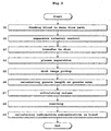
- Fig. 3 is a flow chart showing a sequence of processes relating to a series of quantitative analyses according to the embodiment.
- Fig. 4 is a view schematically showing output of detector signals.
- Fig. 5 is a view schematically showing conditions of plasma and blood cell resulting from a plasma separation.
- Fig. 6 (a) is an outline plan view of a groove in the disk.
- Fig. 6 (b) is an outline sectional view of the groove in the disk.
- Fig. 7 is a graph of a blood radioactive concentration curve.
- Step S1 Feeding blood to main flow path
- Blood is continuously fed into the main flow path 13 by inserting the catheter 15 (see Fig. 1 ) into a mouse artery, and directing arterial blood delivering Itself under mouse blood pressure to the main flow path 13 (seeing Figs. 1 and 2 ) through the catheter 15.
- the detector signal is outputted at Low level from the photodiodes 22.
- the controller 50 controls the volume of the blood to be taken out by the pressure generator 30 (see Fig. 2 ) by controlling intervals of the separators (i.e. bubbles in this embodiment).
- the light source 21 and photodiodes 22 form a linear optical system
- the light source 21 is a linear light source extending along the longitudinal direction of the main flow path 13, and a linear photodiode array formed of the plurality of photodiodes 22 arranged along the same direction
- outputs of the detector signal relative to distance are obtained from detections by the respective photodiodes 22.
- an interval where the detector signal is at Low level is a length where the blood is flowing continuously
- an interval where the detector signal is at High level is a length of a separator between blood and blood.
- a volume of the blood to be taken out is derived from this blood interval (i.e. the separator length). That is, a volume of the blood to be taken out can be determined by multiplying the blood interval by the cross-sectional area of the main flow path 13.
- the controller 30 controls pressure regulation to the pressure generator 30, and the timing of feeding the gas to the main flow path 13 (see Figs. 1 and 2 ) through the side path 14 (see Figs. 1 and 2 ), in order to control the volume of the blood to be taken out by the pressure generator 30 (see Fig. 2 ). And the intervals of the separators (bubbles) are thereby controlled to control the volume of the blood to be taken out.
- an interval between the adjoining separators i.e. an interval of the blood to be taken out
- intervals of the separators may be controlled as above.
- the volume of blood to be taken out may be controlled by controlling directly space intervals (intervals of length) of the blood, or the space intervals (intervals of length) of the separators.
- the volume of blood to be taken out may be controlled by controlling time intervals of the separators (cycle of the separator feeding timing) as above.
- Very small amounts of blood taken out in step S2 are fed into the dispenser 23 (see Figs. 1 and 2 ) through the blood piping 17 (see Figs. 1 and 2 ).
- the dispenser 23 drips each very small amount of the taken-out blood to an opening 25 (see Fig. 1 ) of the disk (CD well) 24 (see Figs. 1 and 2 ).
- the openings 25 and grooves 26 are formed in the disk 24, and are used, in a number at least corresponding to the number of times of blood collection (i.e. the number of collected blood samples).
- the controller 50 controls the rotating unit 31 (see Fig. 2 ) to rotate the disk 24 and carry out plasma separation for dividing into plasma and blood cell.
- the openings 25 are open at one outer end thereof to be connected in a one-to-one relationship to the grooves 26 (see Fig. 1 ), thereby to carry out separation of the blood smoothly at the time of plasma separation.
- Reference BP in Fig. 5 denotes plasma. It is preferable to close the openings 25 for standby in order to prevent blood clotting during a standby time before the plasma separation. As noted in connection with the flow paths, it is preferable to apply an anticoagulant or introduce the anticoagulant to the interiors of the openings 25 and grooves 26 to prevent blood clotting.
- the image pickup unit 32 (see Fig. 2 ) picks up an image of the plasma and blood cell having undergone the plasma separation for each disk 24 (see Figs. 1 and 2 ).
- the image pickup unit 32 With the flat bed scanner acting as the image pickup unit 32, for example, scanning over the disk 24, the photodiode array of the flat bed scanner acquires an optical image of the disk 24 with the plasma and blood cell having undergone the plasma separation, and image pickup is carried out by acquiring the optical image as image of the disk 24.
- the image processor 33 (see Fig. 2 ) carries out various processes on the image of the disk 24.
- the image pickup unit 32 is not limited to the type that picks up images optically, but may pick up images by detecting emitted radiation, for example.
- the groove length and groove area calculating unit 34 obtains a groove length or a groove area of each part of the plasma and blood cell.
- the groove length or groove area of each part of the plasma and blood cell is obtained by converting the number of one-dimensional pixels with the shade difference into the groove length, or by converting the number of two-dimensional pixels into the groove area.
- the volume calculating unit 35 Based on the groove length of each part of the plasma and blood cell obtained by the groove length and groove area calculating unit 34 (see Fig. 2 ) and the cross-sectional area of the grooves 26 (see Fig. 1 ), or based on the groove area of each part of the plasma and blood cell obtained by the groove length and groove area calculating unit 34 and the depth of the grooves 26, the volume calculating unit 35 (see Fig. 2 ) obtained a volume of each part.
- the length in the longitudinal direction of groove 26 (including opening 25), i.e. the groove length, is assumed to be x.
- the depth of groove 26 is assumed to be d.
- the length in the transverse direction of groove 26, i.e. groove width is assumed to be L.
- the volume of plasma is assumed to be Vp, and the volume of blood cell to be V h .
- Each disk 24 with the plasma and blood cell having undergone the plasma separation (refer to Figs. 1 and 2 ) is stored as a sample in an opened cassette not shown, the imaging plate IP (see Fig. 1 ) is stored thereon, and the cassette is closed.
- the disk 24 is taken out of the cassette after a fixed time, and the imaging plate IP is irradiated with light for exposure. Through this exposure, electrons are captured by lattice defects of a fluorescent substance (not shown) of the imaging plate IP due to the ionizing power of ⁇ + rays included in the blood.
- the exposed imaging plate IP is taken out of the cassette, and is inserted in the cover of the reading unit 41 (see Figs. 1 and 2 ) of the measuring apparatus 40 (see Figs. 1 and 2 ).
- Laser is emitted from the laser light source 42 (see Figs. 1 and 2 ) of the reading unit 41 (see Figs. 1 and 2 ) to the imaging plate IP (see Fig. 1 ).
- the captured electrons are excited to be conductors to recombine with holes, and are excited as light from the fluorescent substance.
- the photomultiplier tube 43 (see Figs. 1 and 2 ) converts into electrons and multiplies the light excited by the laser irradiation of this imaging plate IP, thereby simultaneously detecting in two dimensions and counting as electrical pulses.
- the captured electrons are eliminated for reuse by emitting light from a light source for elimination (not shown) to the imaging plate IP.
- the information calculating unit 44 determines a radioactive concentration in the blood which is count information on ⁇ + rays per unit volume.
- the image of the disk 24 picked up by the image pickup unit 32 (see Fig. 2 ) and a distribution image of ⁇ + rays which is the count information obtained by the imaging plate IP and reading unit 41 are superimposed together, to match the plasma in the image of the disk 24 and the plasma in the distribution image of ⁇ + rays, and to match the blood cell in the image of the disk 24 and the blood cell in the distribution image of ⁇ + rays. Then, a radioactive concentration in blood of each part is determined by dividing the count of each part by the volume of each part.
- radioactive concentration in blood A p /V p in the plasma is calculated, and radioactive concentration in blood A h /V h in the blood cell is calculated.
- the output value of the imaging plate IP and reading unit 41 is corrected beforehand with a known dose of radiation.
- a graph of a radioactive concentration curve in blood is obtained finally as shown in Fig. 7 by rearranging results of the radioactive concentration in blood according to extraction time.
- the horizontal axis in Fig. 7 is extraction time, i.e. acquisition time (written "Acquisition time” in Fig. 7 ), while the vertical axis in Fig. 7 is the radioactive concentration in blood (written "PET equivalent counts” in Fig. 7 ).
- the volume of the extracted blood is determined by the cross-sectional area of grooves 26 (see Figs. 1 and 2 ) of the disk 24 (see Figs. 1 and 2 ) and image pickup accuracy of the image pickup unit 32 (see Fig. 2 ).
- the counting accuracy (statistical accuracy) of the radiation is determined by the exposure time to the imaging plate IP. Considering attenuation of the radiation and a required sampling number, a plurality of disks 24 may be made available and exposed successively with the imaging plate IP to pick up images.
- the blood collecting apparatus 10 includes (a) a flow path (main flow path 13 in this embodiment) and (b) an extracting device (pressure generator 30 in this embodiment).
- the extracting device (pressure generator 30) is provided in an intermediate position of the flow path (main flow path 13) to insert, as separators at designated predetermined intervals, a gas (air, argon or the like in this embodiment) or a liquid (mineral oil, fluorine-based oil or the like where the liquid to be measured Is blood) other than the above-noted liquid to be measured (blood in this embodiment), thereby to take out the liquid (blood) to be measured, as separated in a time series.
- the liquid (blood) can be taken out in minute volumes of about 1 [ ⁇ L], for example, by inserting the separators consisting of the gas or liquid while feeding the above liquid (blood) continuously into the flow path (main flow path 13) in this way. And consumption of the liquid (blood) to be measured accompanying a cleaning liquid (heparin solution in the case of blood collection) for every collection as in the prior art can be held down, and the amount of collected liquid (the quantity of collected blood in this embodiment) can be minimized. Since the operation to insert the separators is excellent in speed, repeated collection in a short time, i.e. frequency of collection (blood collection in this embodiment), can be secured. As a result, the amount of collected liquid (the quantity of collected blood) can be reduced, and the frequency of collection (blood collection) can be secured.
- the main flow path 13 preferably, is formed of what has been grooved in a predetermined size in the planar glass substrate 11. That is, with grooving in the predetermined size, if a groove length or a groove area of the liquid (blood in this embodiment) fed into the main flow path 13 is known, a volume of the liquid (blood) fed into the main flow path 13 can be specified based on the cross-sectional area of the groove or the depth of the groove formed by grooving in the predetermined size.
- the blood collecting apparatus 10 preferably, includes (c) an optical measuring device (light source 21 and photodiodes 22 in this embodiment).
- the above optical measuring device measures length information on the liquid (blood) while optically monitoring the liquid to be measured (blood in this embodiment blood) flowing through the flow path (main flow path 13 in this embodiment).
- the volume of the liquid (blood) to be taken out by the above extracting device (pressure generator 30 in this embodiment) is controlled by controlling the intervals of the separators based on a result of measurement by the optical measuring device (light source 21 and photodiodes 22).
- the flow rate of the liquid (blood), and thus the volume of the liquid (blood) can be controlled by the intervals of the separators, and the amount of collected liquid (the amount of collected blood) can be minimized.
- This embodiment is applied to centrifugal separation of the liquid. That is, (d) a flat plate (disk 24 in this embodiment) and (e) a rotating device (rotating unit 31 in this embodiment) are provided, the flat plate (disk 24) has a plurality of grooves formed to allow the liquid to be measured to circulate with respect to the flow path (main flow path 13 in this embodiment) (to allow circulation with the dispenser 23 interposed) and formed radially, and the rotating device (rotating unit 31) rotates the flat plate (disk 24). It is possible to centrifuge the liquid using a centrifugal force of the flat plate (disk 24) by the rotating device (rotating unit 31). Where the liquid is blood as in this embodiment, it is possible to centrifuge the blood by using the centrifugal force of the flat plate (disk 24) by the rotating device (rotating unit 31), to effect plasma separation to divide into plasma and blood cell.
- an image pickup device image pickup unit 32 in this embodiment
- a groove length and the groove area calculating device groove length and groove area calculating 34 in this embodiment
- a volume calculating device volume calculating unit 35 in this embodiment
- the difference in absorbance or radioactive concentration results in the plasma and blood cell appearing as a shade difference on the image picked up, rendering them easily discernible on the image.
- the groove length and groove area calculating device obtains a groove length or a groove area of each part of the centrifuged liquid (each part of the plasma and blood cell in this embodiment).
- the volume calculating device Based on the groove length of each part of the liquid (each part of the plasma and blood cell) obtained by the groove length and groove area calculating device (groove length and groove area calculating unit 34) and the cross-sectional area of the grooves 26, or based on the groove area of each part of the liquid (each part of the plasma and blood cell) obtained by the groove length and groove area calculating device (groove length and groove area calculating unit 34) and the depth of the grooves 26, the volume calculating device (volume calculating unit 35) obtains a volume of each part noted above (each part of the plasma and blood cell).
- each part of the liquid each part of the plasma and blood cell
- the groove length and groove area calculating device groove length and groove area calculating unit 34
- the volume of each part can be obtained based on the cross-sectional area of grooves 26 or the depth of grooves 26.
- a variation such as a decrease in the volume of the liquid (blood) is conceivable in that the liquid (blood in this embodiment) specified in the flow path (main flow path 13 in this embodiment) located upstream of the flat plate (disk 24 in this embodiment) is transferred to the flat plate (disk 24).
- the volume of each part can be determined with increased accuracy since the volume of each part of the liquid (each part of the plasma and blood cell in this embodiment) stored in the flat plate (disk 24) is determined again by using the image information (shade difference of the image) on the flat plate (disk 24) picked up by the image pickup device (image pickup unit 32 in this embodiment).
- the liquid collecting apparatus is an apparatus for collecting blood, i.e. the blood collecting apparatus 10.
- the measuring apparatus 40 includes (A) a detecting device (imaging plate IP and reading unit 41 in this embodiment) and (B) an information calculating device (information calculating unit 44 in this embodiment). Based on a volume of the liquid (blood) determined from image information on the flat plate (disk 24 in this embodiment) storing the liquid (blood in this embodiment) and having a plurality of grooves and information on the grooves 26 grooved in the flat plate (disk 24), and two-dimensional image information on light or radiation (count information on radiation in this embodiment) obtained by the detecting device (imaging plate IP and reading unit 41), the information calculating device (information calculating unit 44) obtains information on light or radiation per unit volume (radioactive concentration in blood in this embodiment).
- the detecting device (imaging plate IP and reading unit 41) can reduce the influence of photobleaching of light or attenuation of radiation by carrying out simultaneous detection in two dimensions.
- the imaging plate IP and reading unit 41 detect and count the radiation included in the blood.
- the information calculating device (information calculating unit 35 in this embodiment) can obtain count information on the radiation per unit volume (radioactive concentration in blood in this embodiment) accurately.
- the imaging plate IP and reading unit 41 count and detect separately, as two-dimensional radiation information, the radiation included in the plasma and blood cell resulting from a plasma separation centrifuging the blood. Based on the volume of each part of the plasma and blood cell and count information on the radiation of each part obtained by the imaging plate IP and reading unit 41, the information calculating device (information calculating unit 35 in this embodiment) obtains the count information on each part per unit volume (radioactive concentration in blood in this embodiment). It is possible to determine volumes of all parts of the plasma and blood cell on the disk 24 in parallel, thereby to obtain count information on each part per unit volume (radioactive concentration in blood in this embodiment) in parallel (i.e. to obtain at the same time). This simultaneous calculation can extend detection time (measuring time) by the imaging plate IP, which provides also an advantage that a low-concentration dose of radiation can be measured with high statistical accuracy.
- the blood collecting and measuring system including the blood collecting apparatus 10 and measuring apparatus 40
- the measuring apparatus 40 as with the measuring apparatus 40 according to this embodiment, as for the liquid (blood in this embodiment) already transferred to the flat plate (disk 24), no variation such as a subsequent decrease occurs with the volume of the liquid (blood) derived from the image information on the flat plate (disk 24 in this embodiment) and the information on the grooves 26 grooved in the flat plate (disk 24), and based on the volume of the liquid (blood), the information on light or radiation per unit volume (radioactive concentration in blood in this embodiment) is obtained. Therefore, by using the image information on the flat plate (disk 24), the information on the light or the radiation per unit volume (radioactive concentration in blood) can be obtained accurately, with no variation in the volume of the liquid (blood).
- the blood collecting and measuring system includes (a) a flow path (main flow path 13 in this embodiment) and (b) an extracting device (pressure generator 30 in this embodiment).
- the extracting device (pressure generator 30) inserts, as separators at designated predetermined intervals, a gas (air, argon or the like in this embodiment) or a liquid (mineral oil, fluorine-based oil or the like where the liquid to be measured is blood) other than the above-noted liquid to be measured (blood in this embodiment), thereby to take out, as separated in a time series, the liquid (blood) to be measured.
- the measuring apparatus 40 included in the system measures light generating from a luminescent or fluorescent substance included in the liquid (blood) or radiation included in the liquid (blood) to be measured (only radiation in this embodiment).
- the amount of collected liquid can be reduced, and the frequency of collection (blood collection) can be secured.
- the information on light or radiation per unit volume can be obtained accurately.
- the above main flow path 13 preferably, is formed of what has been grooved in a predetermined size in the planar glass substrate 11. It is also preferred to include (c) an optical measuring device (light source 21 and photodiodes 22 in this embodiment). For application to centrifugal separation of the liquid (blood in this embodiment), (d) a flat plate (disk 24 in this embodiment) and (e) a rotating device (rotating unit 31 in this embodiment) are provided.
- the flat plate (disk 24) is the same as the flat plate which stores the liquid (blood) to be measured, and has a plurality of grooves formed in the predetermined size. The plurality of grooves are formed to allow the liquid (blood) to be measured to circulate with respect to the flow path (main flow path 13), and are formed to extend radially.
- an image pickup device image pickup unit 32 in this embodiment
- a groove length and the groove area calculating device groove length and groove area calculating 34 in this embodiment
- a volume calculating device volume calculating unit 35 in this embodiment
- the shade difference of the image described with relation to the blood collecting apparatus 10 corresponds to the image information of the flat plate (disk 24 in this embodiment) in the blood collecting and measuring system.
- the cross-sectional area of grooves 26 or the depth of the grooves described with the blood collecting apparatus 10 corresponds to the information on the grooves in the blood collecting and measuring system.
- the imaging plate IP and reading unit 41 detect and count the radiation included in the blood.
- the imaging plate IP and reading unit 41 count and detect separately the radiation included in the plasma and blood cell resulting from the plasma separation centrifuging the blood.
- the information calculating device obtains the count information on each part per unit volume (radioactive concentration in blood in this embodiment).
Claims (8)
- Flüssigkeitssammel- und Messsystem mit einer Flüssigkeitssammelvorrichtung (10) zum Sammeln einer zu messenden Flüssigkeit, wobei die Flüssigkeitssammelvorrichtung (10) einen flachen Teller (24) mit mehreren Rillen (26) zum Aufbewahren der Flüssigkeit umfasst, und einer Messvorrichtung (40) zum Messen von Licht, das von einer in der gesammelten Flüssigkeit enthaltenen lumineszierenden oder fluoreszierenden Substanz erzeugt wird, oder von in der Flüssigkeit enthaltener Strahlung, die (A) eine Erfassungsvorrichtung (IP, 41) zum gleichzeitigen Erfassen des Lichts oder der Strahlung in zwei Dimensionen zum Erhalten von zweidimensionalen Bildinformationen bezüglich des Lichts oder der Strahlung und (B) eine Informationsberechnungsvorrichtung (44) zum Erhalten von Informationen bezüglich des Lichts oder der Strahlung pro Einheitsvolumen umfasst, dadurch gekennzeichnet, dass
die Informationsberechnungsvorrichtung (44) dazu konfiguriert ist, Informationen bezüglich des Lichts oder der Strahlung pro Einheitsvolumen basierend auf einem Volumen der Flüssigkeit, das anhand von Bildinformationen bezüglich des flachen Tellers (24), der die Flüssigkeit aufbewahrt und mehrere Rillen (26) aufweist, und Informationen bezüglich der Rillen (26), die in dem flachen Teller (24) eingekerbt sind, bestimmt wird, und den zweidimensionalen Bildinformationen bezüglich des Lichts oder der Strahlung, die von der Erfassungsvorrichtung (IP, 41) erhalten werden, zu erhalten. - Flüssigkeitssammel- und Messsystem nach Anspruch 1, wobei die Flüssigkeitssammelvorrichtung (10) (a) einen Strömungsweg (13), durch den die zu messende Flüssigkeit strömt, und (b) eine Extrahierungsvorrichtung (30) enthält, die an einer Zwischenposition des Strömungswegs (13) vorgesehen ist, um ein Gas oder eine Flüssigkeit, bei der es sich nicht um die zu messende Flüssigkeit handelt, in bestimmten vorgegebenen Intervallen als Trennelemente einzuführen, um dadurch die zu messende, entlang einer Zeitreihe getrennte Flüssigkeit herauszunehmen, und wobei die Messvorrichtung (40) für jede von der Extrahierungsvorrichtung (30) herausgenommene Flüssigkeit das Licht, das von einer in der Flüssigkeit enthaltenen lumineszierenden oder fluoreszierenden Substanz erzeugt wird, oder die in der zu messenden Flüssigkeit enthaltene Strahlung misst.
- Flüssigkeitssammel- und Messsystem nach Anspruch 2, wobei der Strömungsweg (13) von Einkerbungen einer vorgegebenen Größe in einem planaren Substrat (11) gebildet wird.
- Flüssigkeitssammel- und Messsystem nach Anspruch 2 oder 3, wobei die Flüssigkeitssammelvorrichtung (10) (c) eine optische Messvorrichtung (21, 22) zum Messen von Längeninformationen bezüglich der Flüssigkeit, während die optische Messvorrichtung (21, 22) die durch den Strömungsweg (13) strömende zu messenden Flüssigkeit optisch überwacht, enthält, wobei ein Volumen der von der Extrahierungsvorrichtung (30) herauszunehmenden Flüssigkeit durch die Steuerung der Intervalle der Trennelemente basierend auf einem Messergebnis von der optischen Messvorrichtung (21, 22) gesteuert wird.
- Flüssigkeitssammel- und Messsystem nach einem der Ansprüche 2 bis 4, wobei die
Flüssigkeitssammelvorrichtung (10) (d) den flachen Teller (24) mit den mehreren Rillen (26), die dazu gebildet sind, es der zu messenden Flüssigkeit zu ermöglichen, in Bezug auf den Strömungsweg (13) zu zirkulieren, und die radial gebildet sind, und (e) eine Rotationsvorrichtung (31) zum Drehen des flachen Tellers (24) enthält, wobei die Flüssigkeit unter Verwendung einer Zentrifugalkraft des flachen Tellers (24) durch die Rotationsvorrichtung (31) zentrifugiert wird. - Flüssigkeitssammel- und Messsystem nach Anspruch 5, wobei die Flüssigkeitssammelvorrichtung (10) (f) eine Bildaufnahmevorrichtung (32) zum Aufnehmen eines Bilds von dem flachen Teller, (g) eine Rillenlängen- und Rillenflächenberechnungsvorrichtung (34) zum Bestimmen einer Rillenlänge oder einer Rillenfläche von jedem Teil der zentrifugierten Flüssigkeit basierend auf den Bildinformationen bezüglich des flachen Tellers (24), bei denen es sich um einen Farbtonunterschied des von der Bildaufnahmevorrichtung (32) aufgenommenen Bilds von den Rillen (26), die in den flachen Teller (24) eingekerbt sind, handelt, und (h) eine Volumenberechnungsvorrichtung (35) zum Bestimmen eines Volumens von jedem Teil basierend auf den Informationen bezüglich der Rillen (26), bei denen es sich um die Rillenlänge jedes Teils der Flüssigkeit, die von der Rillenlängen- und Rillenflächenberechnungsvorrichtung (34) bestimmt wird, handelt, und einer Querschnittsfläche der Rillen (26), oder basierend auf den Informationen bezüglich der Rillen (26), bei denen es sich um die Rillenfläche jedes Teils der Flüssigkeit, die von der Rillenlängen- und Rillenflächenberechnungsvorrichtung (34) bestimmt wird, handelt, und einer Tiefe der Rillen (26), enthält, und wobei die Informationsberechnungsvorrichtung (44) Informationen bezüglich des Lichts oder der Strahlung pro Einheitsvolumen basierend auf dem Volumen der Flüssigkeit, das von der Volumenberechnungsvorrichtung (35) bestimmt wird, und auf den zweidimensionalen Bildinformationen bezüglich des Lichts oder der Strahlung, die von der Erfassungsvorrichtung (IP, 41) erhalten werden, erhält.
- Flüssigkeitssammel- und Messsystem nach einem der Ansprüche 1 bis 6, wobei es sich bei der zu messenden Flüssigkeit um Blut handelt und wobei es sich bei der Flüssigkeitssammelvorrichtung (10) um eine Vorrichtung zum Sammeln des Bluts handelt, und wobei die Erfassungsvorrichtung (IP, 41) zählt, indem sie die in dem Blut enthaltene Strahlung erfasst, und die Informationsberechnungsvorrichtung (44) Zählinformationen bezüglich der Strahlung pro Einheitsvolumen basierend auf einem Blutvolumen und Zählinformationen bezüglich der Strahlung, die von der Erfassungsvorrichtung (IP, 41) erhalten werden, erhält.
- Flüssigkeitssammel- und Messsystem nach Anspruch 7, wobei die Erfassungsvorrichtung (IP, 41) zählt, indem sie die in Plasma- und Blutzellen, die aus einer Plasmaseparation resultieren, bei welcher das Blut zentrifugiert wird, enthaltene Strahlung separat erfasst, und die Informationsberechnungsvorrichtung (44) Zählinformationen für jedes Teil pro Einheitsvolumen basierend auf einem Volumen von jedem Teil des Bluts und der Blutzelle und den Zählinformationen bezüglich der Strahlung von jedem Teil, die von der Erfassungseinheit (IP, 41) erhalten werden, erhält.
Applications Claiming Priority (1)
| Application Number | Priority Date | Filing Date | Title |
|---|---|---|---|
| PCT/JP2008/050803 WO2009093306A1 (ja) | 2008-01-22 | 2008-01-22 | 液体採取装置、測定装置並びにそれらを備えた液体採取測定システム |
Publications (3)
| Publication Number | Publication Date |
|---|---|
| EP2239585A1 EP2239585A1 (de) | 2010-10-13 |
| EP2239585A4 EP2239585A4 (de) | 2013-07-10 |
| EP2239585B1 true EP2239585B1 (de) | 2016-11-30 |
Family
ID=40900824
Family Applications (1)
| Application Number | Title | Priority Date | Filing Date |
|---|---|---|---|
| EP08703647.1A Not-in-force EP2239585B1 (de) | 2008-01-22 | 2008-01-22 | Flüssigkeitssammel- und messsystem |
Country Status (5)
| Country | Link |
|---|---|
| US (1) | US8358405B2 (de) |
| EP (1) | EP2239585B1 (de) |
| JP (1) | JP5066583B2 (de) |
| CN (1) | CN101925821B (de) |
| WO (1) | WO2009093306A1 (de) |
Families Citing this family (24)
| Publication number | Priority date | Publication date | Assignee | Title |
|---|---|---|---|---|
| US8088593B2 (en) | 2007-10-02 | 2012-01-03 | Theranos, Inc. | Modular point-of-care devices, systems, and uses thereof |
| JP2011075420A (ja) * | 2009-09-30 | 2011-04-14 | Shimadzu Corp | 遠心分離装置 |
| US8101065B2 (en) * | 2009-12-30 | 2012-01-24 | Lifescan, Inc. | Systems, devices, and methods for improving accuracy of biosensors using fill time |
| WO2011117953A1 (ja) * | 2010-03-24 | 2011-09-29 | 株式会社島津製作所 | 測定システム |
| US9498154B2 (en) | 2010-03-24 | 2016-11-22 | Shimadzu Corporation | Measuring system capable of separating liquid and determining boundary of separated liquid |
| CN111982829A (zh) | 2011-01-21 | 2020-11-24 | 拉布拉多诊断有限责任公司 | 样品使用最大化的系统和方法 |
| JP2014211308A (ja) * | 2011-08-31 | 2014-11-13 | 株式会社島津製作所 | 液体滴下補助装置 |
| US20140170735A1 (en) | 2011-09-25 | 2014-06-19 | Elizabeth A. Holmes | Systems and methods for multi-analysis |
| US9664702B2 (en) | 2011-09-25 | 2017-05-30 | Theranos, Inc. | Fluid handling apparatus and configurations |
| US9632102B2 (en) | 2011-09-25 | 2017-04-25 | Theranos, Inc. | Systems and methods for multi-purpose analysis |
| US8475739B2 (en) | 2011-09-25 | 2013-07-02 | Theranos, Inc. | Systems and methods for fluid handling |
| JP5724780B2 (ja) * | 2011-09-14 | 2015-05-27 | 株式会社島津製作所 | 測定システムに用いられる表示装置 |
| US10012664B2 (en) | 2011-09-25 | 2018-07-03 | Theranos Ip Company, Llc | Systems and methods for fluid and component handling |
| EP3865875A1 (de) * | 2011-09-25 | 2021-08-18 | Labrador Diagnostics LLC | Systeme und verfahren für mehrfachanalyse |
| US9810704B2 (en) | 2013-02-18 | 2017-11-07 | Theranos, Inc. | Systems and methods for multi-analysis |
| US20140253594A1 (en) * | 2011-10-19 | 2014-09-11 | Shimadzu Corporation | Display apparatus, a display method and a display program for use in a measuring system |
| JP5899829B2 (ja) * | 2011-11-08 | 2016-04-06 | 株式会社島津製作所 | 測定システムに用いられる表示装置、表示方法並びに表示プログラム |
| JP2014032097A (ja) * | 2012-08-03 | 2014-02-20 | Hitachi High-Technologies Corp | 分析システム及び分析方法 |
| WO2014033797A1 (ja) * | 2012-09-03 | 2014-03-06 | 株式会社島津製作所 | 液体滴下方法 |
| US9726658B2 (en) | 2014-04-25 | 2017-08-08 | Shimadzu Corporation | Display device, display method, and display program used in measurement system |
| PL3094252T3 (pl) * | 2014-10-14 | 2022-02-21 | Becton, Dickinson And Company | Zarządzanie próbką krwi z zastosowaniem pianki otwartokomórkowej |
| US9460562B2 (en) | 2015-01-09 | 2016-10-04 | International Business Machines Corporation | Providing volume indicators based on received images of containers |
| JP7024461B2 (ja) * | 2018-02-01 | 2022-02-24 | 株式会社島津製作所 | マイクロ流路内に保持された検体の前処理方法、その前処理方法を実行するための前処理装置及びその前処理装置を備えた分析システム |
| US11852587B2 (en) * | 2018-07-23 | 2023-12-26 | Shimadzu Corporation | Microfluidic device observation apparatus |
Family Cites Families (11)
| Publication number | Priority date | Publication date | Assignee | Title |
|---|---|---|---|---|
| US3679367A (en) * | 1970-09-14 | 1972-07-25 | Technicon Instr | Apparatus for determining the pack volume of particulates in liquid mixtures |
| JPS56147013A (en) * | 1980-04-17 | 1981-11-14 | Kyoto Denshi Kogyo Kk | Detecting method for flow rate of liquid |
| JPH01307608A (ja) * | 1988-06-06 | 1989-12-12 | Hitachi Ltd | 流体量計測装置 |
| DE19542225B4 (de) * | 1995-11-01 | 2011-05-26 | L.U.M. Gmbh | Verfahren und Vorrichtung zur Bestimmung von rheologischen und mechanischen Stoffkenngrößen |
| US6388740B1 (en) * | 1999-06-22 | 2002-05-14 | Robert A. Levine | Method and apparatus for timing intermittent illumination of a sample tube positioned on a centrifuge platen and for calibrating a sample tube imaging system |
| JP3803078B2 (ja) * | 2002-09-20 | 2006-08-02 | 独立行政法人科学技術振興機構 | 血液分析装置及び血漿分離方法 |
| JP2004294366A (ja) * | 2003-03-28 | 2004-10-21 | Seitai Kagaku Kenkyusho:Kk | ラジオ液体クロマトグラフ |
| KR100552706B1 (ko) | 2004-03-12 | 2006-02-20 | 삼성전자주식회사 | 핵산 증폭 방법 및 장치 |
| JP4170947B2 (ja) | 2004-04-09 | 2008-10-22 | 株式会社日立ハイテクノロジーズ | 生体試料成分検出法及びその装置 |
| WO2006005371A1 (en) * | 2004-07-13 | 2006-01-19 | Commissariat A L'energie Atomique | Microfluidic device for performing a plurality of reactions and uses thereof |
| WO2006106962A1 (ja) * | 2005-03-31 | 2006-10-12 | Kabushiki Kaisha Toshiba | 蛍光測定装置、蛍光測定方法、蛍光測定用収納容器および蛍光測定用収納容器の製造方法 |
-
2008
- 2008-01-22 WO PCT/JP2008/050803 patent/WO2009093306A1/ja active Application Filing
- 2008-01-22 US US12/863,968 patent/US8358405B2/en not_active Expired - Fee Related
- 2008-01-22 EP EP08703647.1A patent/EP2239585B1/de not_active Not-in-force
- 2008-01-22 CN CN200880125368.3A patent/CN101925821B/zh not_active Expired - Fee Related
- 2008-01-22 JP JP2009550391A patent/JP5066583B2/ja not_active Expired - Fee Related
Also Published As
| Publication number | Publication date |
|---|---|
| CN101925821B (zh) | 2014-09-24 |
| EP2239585A1 (de) | 2010-10-13 |
| JPWO2009093306A1 (ja) | 2011-05-26 |
| CN101925821A (zh) | 2010-12-22 |
| WO2009093306A1 (ja) | 2009-07-30 |
| US20100294950A1 (en) | 2010-11-25 |
| EP2239585A4 (de) | 2013-07-10 |
| US8358405B2 (en) | 2013-01-22 |
| JP5066583B2 (ja) | 2012-11-07 |
Similar Documents
| Publication | Publication Date | Title |
|---|---|---|
| EP2239585B1 (de) | Flüssigkeitssammel- und messsystem | |
| US8783121B2 (en) | Liquid collecting system and a method therefor | |
| US9498154B2 (en) | Measuring system capable of separating liquid and determining boundary of separated liquid | |
| EP1701150B1 (de) | Leukozytenzählung | |
| JP4336834B2 (ja) | チップの使用方法及び検査チップ | |
| US5827746A (en) | Method to determine the sedimentation of blood and relative device | |
| US20170328924A1 (en) | Automated microscopic cell analysis | |
| CN109613293A (zh) | 流体样品分析系统 | |
| WO2009094761A1 (en) | Apparatus and method for urinalysis | |
| CN103109184A (zh) | 细胞分析装置 | |
| JP5298237B2 (ja) | 測定システム | |
| JP2011075420A (ja) | 遠心分離装置 | |
| JP2007333716A (ja) | 分離・秤量チップならびにその使用方法 | |
| KR20210138640A (ko) | 현장 진단 농도 분석기 | |
| WO2018091922A1 (en) | Sample detection device | |
| US20130035223A1 (en) | System and Method for the Continuous Extraction of a Liquid Phase of Microsamples, and Automated Installation for Taking Them, For Carrying Out the Extraction and Taking Measurements | |
| CN108362615B (zh) | 一种分析检测用装置及细胞或颗粒检测方法 | |
| US20140253594A1 (en) | Display apparatus, a display method and a display program for use in a measuring system | |
| KR20220018000A (ko) | 라인 부피 캘리브레이션 시스템 및 방법 | |
| JP6098315B2 (ja) | 光または放射線測定用容器並びに測定システム | |
| CN219201334U (zh) | 一种流式荧光检测液路系统 | |
| JP6218352B2 (ja) | 測定システムに用いられる表示装置、表示方法並びに表示プログラム | |
| WO2013031240A1 (ja) | 液体滴下補助装置 | |
| JPH02213744A (ja) | サンプル検査方法及び装置 |
Legal Events
| Date | Code | Title | Description |
|---|---|---|---|
| PUAI | Public reference made under article 153(3) epc to a published international application that has entered the european phase |
Free format text: ORIGINAL CODE: 0009012 |
|
| 17P | Request for examination filed |
Effective date: 20100812 |
|
| AK | Designated contracting states |
Kind code of ref document: A1 Designated state(s): AT BE BG CH CY CZ DE DK EE ES FI FR GB GR HR HU IE IS IT LI LT LU LV MC MT NL NO PL PT RO SE SI SK TR |
|
| AX | Request for extension of the european patent |
Extension state: AL BA MK RS |
|
| DAX | Request for extension of the european patent (deleted) | ||
| A4 | Supplementary search report drawn up and despatched |
Effective date: 20130612 |
|
| RIC1 | Information provided on ipc code assigned before grant |
Ipc: G01N 35/08 20060101AFI20130606BHEP Ipc: G01N 1/00 20060101ALI20130606BHEP Ipc: G01T 1/161 20060101ALI20130606BHEP Ipc: G01N 21/78 20060101ALI20130606BHEP |
|
| 17Q | First examination report despatched |
Effective date: 20140428 |
|
| GRAP | Despatch of communication of intention to grant a patent |
Free format text: ORIGINAL CODE: EPIDOSNIGR1 |
|
| INTG | Intention to grant announced |
Effective date: 20160330 |
|
| GRAP | Despatch of communication of intention to grant a patent |
Free format text: ORIGINAL CODE: EPIDOSNIGR1 |
|
| INTG | Intention to grant announced |
Effective date: 20160608 |
|
| RAP1 | Party data changed (applicant data changed or rights of an application transferred) |
Owner name: SHIMADZU CORPORATION Owner name: NATIONAL INSTITUTES FOR QUANTUM AND RADIOLOGICAL S |
|
| GRAS | Grant fee paid |
Free format text: ORIGINAL CODE: EPIDOSNIGR3 |
|
| GRAA | (expected) grant |
Free format text: ORIGINAL CODE: 0009210 |
|
| RIN1 | Information on inventor provided before grant (corrected) |
Inventor name: NISHIMOTO, TAKAHIRO Inventor name: KANNO, IWAO Inventor name: KITAMURA, KEISHI Inventor name: SEKI, CHIE Inventor name: KIMURA, YUICHI |
|
| AK | Designated contracting states |
Kind code of ref document: B1 Designated state(s): AT BE BG CH CY CZ DE DK EE ES FI FR GB GR HR HU IE IS IT LI LT LU LV MC MT NL NO PL PT RO SE SI SK TR |
|
| REG | Reference to a national code |
Ref country code: CH Ref legal event code: EP Ref country code: GB Ref legal event code: FG4D |
|
| RIN1 | Information on inventor provided before grant (corrected) |
Inventor name: KITAMURA, KEISHI Inventor name: NISHIMOTO, TAKAHIRO Inventor name: KIMURA, YUICHI Inventor name: KANNO, IWAO Inventor name: SEKI, CHIE |
|
| RIN2 | Information on inventor provided after grant (corrected) |
Inventor name: KANNO, IWAO Inventor name: KIMURA, YUICHI Inventor name: SEKI, CHIE Inventor name: NISHIMOTO, TAKAHIRO Inventor name: KITAMURA, KEISHI |
|
| REG | Reference to a national code |
Ref country code: AT Ref legal event code: REF Ref document number: 850297 Country of ref document: AT Kind code of ref document: T Effective date: 20161215 |
|
| REG | Reference to a national code |
Ref country code: IE Ref legal event code: FG4D |
|
| REG | Reference to a national code |
Ref country code: DE Ref legal event code: R096 Ref document number: 602008047616 Country of ref document: DE |
|
| REG | Reference to a national code |
Ref country code: FR Ref legal event code: PLFP Year of fee payment: 10 |
|
| PG25 | Lapsed in a contracting state [announced via postgrant information from national office to epo] |
Ref country code: LV Free format text: LAPSE BECAUSE OF FAILURE TO SUBMIT A TRANSLATION OF THE DESCRIPTION OR TO PAY THE FEE WITHIN THE PRESCRIBED TIME-LIMIT Effective date: 20161130 |
|
| REG | Reference to a national code |
Ref country code: LT Ref legal event code: MG4D |
|
| REG | Reference to a national code |
Ref country code: NL Ref legal event code: MP Effective date: 20161130 |
|
| REG | Reference to a national code |
Ref country code: AT Ref legal event code: MK05 Ref document number: 850297 Country of ref document: AT Kind code of ref document: T Effective date: 20161130 |
|
| PG25 | Lapsed in a contracting state [announced via postgrant information from national office to epo] |
Ref country code: NO Free format text: LAPSE BECAUSE OF FAILURE TO SUBMIT A TRANSLATION OF THE DESCRIPTION OR TO PAY THE FEE WITHIN THE PRESCRIBED TIME-LIMIT Effective date: 20170228 Ref country code: LT Free format text: LAPSE BECAUSE OF FAILURE TO SUBMIT A TRANSLATION OF THE DESCRIPTION OR TO PAY THE FEE WITHIN THE PRESCRIBED TIME-LIMIT Effective date: 20161130 Ref country code: GR Free format text: LAPSE BECAUSE OF FAILURE TO SUBMIT A TRANSLATION OF THE DESCRIPTION OR TO PAY THE FEE WITHIN THE PRESCRIBED TIME-LIMIT Effective date: 20170301 Ref country code: SE Free format text: LAPSE BECAUSE OF FAILURE TO SUBMIT A TRANSLATION OF THE DESCRIPTION OR TO PAY THE FEE WITHIN THE PRESCRIBED TIME-LIMIT Effective date: 20161130 |
|
| PGFP | Annual fee paid to national office [announced via postgrant information from national office to epo] |
Ref country code: FR Payment date: 20170130 Year of fee payment: 10 Ref country code: DE Payment date: 20170130 Year of fee payment: 10 |
|
| PG25 | Lapsed in a contracting state [announced via postgrant information from national office to epo] |
Ref country code: BE Free format text: LAPSE BECAUSE OF NON-PAYMENT OF DUE FEES Effective date: 20170131 Ref country code: PL Free format text: LAPSE BECAUSE OF FAILURE TO SUBMIT A TRANSLATION OF THE DESCRIPTION OR TO PAY THE FEE WITHIN THE PRESCRIBED TIME-LIMIT Effective date: 20161130 Ref country code: PT Free format text: LAPSE BECAUSE OF FAILURE TO SUBMIT A TRANSLATION OF THE DESCRIPTION OR TO PAY THE FEE WITHIN THE PRESCRIBED TIME-LIMIT Effective date: 20170330 Ref country code: FI Free format text: LAPSE BECAUSE OF FAILURE TO SUBMIT A TRANSLATION OF THE DESCRIPTION OR TO PAY THE FEE WITHIN THE PRESCRIBED TIME-LIMIT Effective date: 20161130 Ref country code: ES Free format text: LAPSE BECAUSE OF FAILURE TO SUBMIT A TRANSLATION OF THE DESCRIPTION OR TO PAY THE FEE WITHIN THE PRESCRIBED TIME-LIMIT Effective date: 20161130 Ref country code: AT Free format text: LAPSE BECAUSE OF FAILURE TO SUBMIT A TRANSLATION OF THE DESCRIPTION OR TO PAY THE FEE WITHIN THE PRESCRIBED TIME-LIMIT Effective date: 20161130 Ref country code: HR Free format text: LAPSE BECAUSE OF FAILURE TO SUBMIT A TRANSLATION OF THE DESCRIPTION OR TO PAY THE FEE WITHIN THE PRESCRIBED TIME-LIMIT Effective date: 20161130 |
|
| PGFP | Annual fee paid to national office [announced via postgrant information from national office to epo] |
Ref country code: GB Payment date: 20170130 Year of fee payment: 10 |
|
| PG25 | Lapsed in a contracting state [announced via postgrant information from national office to epo] |
Ref country code: NL Free format text: LAPSE BECAUSE OF FAILURE TO SUBMIT A TRANSLATION OF THE DESCRIPTION OR TO PAY THE FEE WITHIN THE PRESCRIBED TIME-LIMIT Effective date: 20161130 |
|
| PG25 | Lapsed in a contracting state [announced via postgrant information from national office to epo] |
Ref country code: SK Free format text: LAPSE BECAUSE OF FAILURE TO SUBMIT A TRANSLATION OF THE DESCRIPTION OR TO PAY THE FEE WITHIN THE PRESCRIBED TIME-LIMIT Effective date: 20161130 Ref country code: RO Free format text: LAPSE BECAUSE OF FAILURE TO SUBMIT A TRANSLATION OF THE DESCRIPTION OR TO PAY THE FEE WITHIN THE PRESCRIBED TIME-LIMIT Effective date: 20161130 Ref country code: EE Free format text: LAPSE BECAUSE OF FAILURE TO SUBMIT A TRANSLATION OF THE DESCRIPTION OR TO PAY THE FEE WITHIN THE PRESCRIBED TIME-LIMIT Effective date: 20161130 Ref country code: CZ Free format text: LAPSE BECAUSE OF FAILURE TO SUBMIT A TRANSLATION OF THE DESCRIPTION OR TO PAY THE FEE WITHIN THE PRESCRIBED TIME-LIMIT Effective date: 20161130 Ref country code: DK Free format text: LAPSE BECAUSE OF FAILURE TO SUBMIT A TRANSLATION OF THE DESCRIPTION OR TO PAY THE FEE WITHIN THE PRESCRIBED TIME-LIMIT Effective date: 20161130 |
|
| PG25 | Lapsed in a contracting state [announced via postgrant information from national office to epo] |
Ref country code: IT Free format text: LAPSE BECAUSE OF FAILURE TO SUBMIT A TRANSLATION OF THE DESCRIPTION OR TO PAY THE FEE WITHIN THE PRESCRIBED TIME-LIMIT Effective date: 20161130 Ref country code: BG Free format text: LAPSE BECAUSE OF FAILURE TO SUBMIT A TRANSLATION OF THE DESCRIPTION OR TO PAY THE FEE WITHIN THE PRESCRIBED TIME-LIMIT Effective date: 20170228 Ref country code: BE Free format text: LAPSE BECAUSE OF FAILURE TO SUBMIT A TRANSLATION OF THE DESCRIPTION OR TO PAY THE FEE WITHIN THE PRESCRIBED TIME-LIMIT Effective date: 20161130 |
|
| REG | Reference to a national code |
Ref country code: CH Ref legal event code: PL Ref country code: DE Ref legal event code: R097 Ref document number: 602008047616 Country of ref document: DE |
|
| PG25 | Lapsed in a contracting state [announced via postgrant information from national office to epo] |
Ref country code: MC Free format text: LAPSE BECAUSE OF FAILURE TO SUBMIT A TRANSLATION OF THE DESCRIPTION OR TO PAY THE FEE WITHIN THE PRESCRIBED TIME-LIMIT Effective date: 20161130 |
|
| PLBE | No opposition filed within time limit |
Free format text: ORIGINAL CODE: 0009261 |
|
| STAA | Information on the status of an ep patent application or granted ep patent |
Free format text: STATUS: NO OPPOSITION FILED WITHIN TIME LIMIT |
|
| PG25 | Lapsed in a contracting state [announced via postgrant information from national office to epo] |
Ref country code: LI Free format text: LAPSE BECAUSE OF NON-PAYMENT OF DUE FEES Effective date: 20170131 Ref country code: CH Free format text: LAPSE BECAUSE OF NON-PAYMENT OF DUE FEES Effective date: 20170131 |
|
| REG | Reference to a national code |
Ref country code: IE Ref legal event code: MM4A |
|
| 26N | No opposition filed |
Effective date: 20170831 |
|
| PG25 | Lapsed in a contracting state [announced via postgrant information from national office to epo] |
Ref country code: SI Free format text: LAPSE BECAUSE OF FAILURE TO SUBMIT A TRANSLATION OF THE DESCRIPTION OR TO PAY THE FEE WITHIN THE PRESCRIBED TIME-LIMIT Effective date: 20161130 Ref country code: LU Free format text: LAPSE BECAUSE OF NON-PAYMENT OF DUE FEES Effective date: 20170122 |
|
| PG25 | Lapsed in a contracting state [announced via postgrant information from national office to epo] |
Ref country code: IE Free format text: LAPSE BECAUSE OF NON-PAYMENT OF DUE FEES Effective date: 20170122 |
|
| REG | Reference to a national code |
Ref country code: DE Ref legal event code: R119 Ref document number: 602008047616 Country of ref document: DE |
|
| GBPC | Gb: european patent ceased through non-payment of renewal fee |
Effective date: 20180122 |
|
| PG25 | Lapsed in a contracting state [announced via postgrant information from national office to epo] |
Ref country code: MT Free format text: LAPSE BECAUSE OF NON-PAYMENT OF DUE FEES Effective date: 20170122 |
|
| PG25 | Lapsed in a contracting state [announced via postgrant information from national office to epo] |
Ref country code: FR Free format text: LAPSE BECAUSE OF NON-PAYMENT OF DUE FEES Effective date: 20180131 Ref country code: DE Free format text: LAPSE BECAUSE OF NON-PAYMENT OF DUE FEES Effective date: 20180801 |
|
| REG | Reference to a national code |
Ref country code: FR Ref legal event code: ST Effective date: 20180928 |
|
| PG25 | Lapsed in a contracting state [announced via postgrant information from national office to epo] |
Ref country code: GB Free format text: LAPSE BECAUSE OF NON-PAYMENT OF DUE FEES Effective date: 20180122 |
|
| PG25 | Lapsed in a contracting state [announced via postgrant information from national office to epo] |
Ref country code: HU Free format text: LAPSE BECAUSE OF FAILURE TO SUBMIT A TRANSLATION OF THE DESCRIPTION OR TO PAY THE FEE WITHIN THE PRESCRIBED TIME-LIMIT; INVALID AB INITIO Effective date: 20080122 |
|
| PG25 | Lapsed in a contracting state [announced via postgrant information from national office to epo] |
Ref country code: CY Free format text: LAPSE BECAUSE OF NON-PAYMENT OF DUE FEES Effective date: 20161130 |
|
| PG25 | Lapsed in a contracting state [announced via postgrant information from national office to epo] |
Ref country code: TR Free format text: LAPSE BECAUSE OF FAILURE TO SUBMIT A TRANSLATION OF THE DESCRIPTION OR TO PAY THE FEE WITHIN THE PRESCRIBED TIME-LIMIT Effective date: 20161130 |
|
| PG25 | Lapsed in a contracting state [announced via postgrant information from national office to epo] |
Ref country code: IS Free format text: LAPSE BECAUSE OF FAILURE TO SUBMIT A TRANSLATION OF THE DESCRIPTION OR TO PAY THE FEE WITHIN THE PRESCRIBED TIME-LIMIT Effective date: 20170330 |