EP2239126A1 - Mould for vacuum moulding a corrugated pipe, manufatured pipe and method - Google Patents
Mould for vacuum moulding a corrugated pipe, manufatured pipe and method Download PDFInfo
- Publication number
- EP2239126A1 EP2239126A1 EP10158369A EP10158369A EP2239126A1 EP 2239126 A1 EP2239126 A1 EP 2239126A1 EP 10158369 A EP10158369 A EP 10158369A EP 10158369 A EP10158369 A EP 10158369A EP 2239126 A1 EP2239126 A1 EP 2239126A1
- Authority
- EP
- European Patent Office
- Prior art keywords
- shell
- equal
- duct
- corrugated
- vacuum
- Prior art date
- Legal status (The legal status is an assumption and is not a legal conclusion. Google has not performed a legal analysis and makes no representation as to the accuracy of the status listed.)
- Granted
Links
Images


Classifications
-
- B—PERFORMING OPERATIONS; TRANSPORTING
- B29—WORKING OF PLASTICS; WORKING OF SUBSTANCES IN A PLASTIC STATE IN GENERAL
- B29C—SHAPING OR JOINING OF PLASTICS; SHAPING OF MATERIAL IN A PLASTIC STATE, NOT OTHERWISE PROVIDED FOR; AFTER-TREATMENT OF THE SHAPED PRODUCTS, e.g. REPAIRING
- B29C49/00—Blow-moulding, i.e. blowing a preform or parison to a desired shape within a mould; Apparatus therefor
- B29C49/0015—Making articles of indefinite length, e.g. corrugated tubes
- B29C49/0021—Making articles of indefinite length, e.g. corrugated tubes using moulds or mould parts movable in a closed path, e.g. mounted on movable endless supports
-
- B—PERFORMING OPERATIONS; TRANSPORTING
- B29—WORKING OF PLASTICS; WORKING OF SUBSTANCES IN A PLASTIC STATE IN GENERAL
- B29C—SHAPING OR JOINING OF PLASTICS; SHAPING OF MATERIAL IN A PLASTIC STATE, NOT OTHERWISE PROVIDED FOR; AFTER-TREATMENT OF THE SHAPED PRODUCTS, e.g. REPAIRING
- B29C48/00—Extrusion moulding, i.e. expressing the moulding material through a die or nozzle which imparts the desired form; Apparatus therefor
- B29C48/25—Component parts, details or accessories; Auxiliary operations
- B29C48/30—Extrusion nozzles or dies
- B29C48/303—Extrusion nozzles or dies using dies or die parts movable in a closed circuit, e.g. mounted on movable endless support
-
- B—PERFORMING OPERATIONS; TRANSPORTING
- B29—WORKING OF PLASTICS; WORKING OF SUBSTANCES IN A PLASTIC STATE IN GENERAL
- B29C—SHAPING OR JOINING OF PLASTICS; SHAPING OF MATERIAL IN A PLASTIC STATE, NOT OTHERWISE PROVIDED FOR; AFTER-TREATMENT OF THE SHAPED PRODUCTS, e.g. REPAIRING
- B29C2791/00—Shaping characteristics in general
- B29C2791/004—Shaping under special conditions
- B29C2791/006—Using vacuum
-
- B—PERFORMING OPERATIONS; TRANSPORTING
- B29—WORKING OF PLASTICS; WORKING OF SUBSTANCES IN A PLASTIC STATE IN GENERAL
- B29C—SHAPING OR JOINING OF PLASTICS; SHAPING OF MATERIAL IN A PLASTIC STATE, NOT OTHERWISE PROVIDED FOR; AFTER-TREATMENT OF THE SHAPED PRODUCTS, e.g. REPAIRING
- B29C48/00—Extrusion moulding, i.e. expressing the moulding material through a die or nozzle which imparts the desired form; Apparatus therefor
- B29C48/001—Combinations of extrusion moulding with other shaping operations
- B29C48/0017—Combinations of extrusion moulding with other shaping operations combined with blow-moulding or thermoforming
-
- B—PERFORMING OPERATIONS; TRANSPORTING
- B29—WORKING OF PLASTICS; WORKING OF SUBSTANCES IN A PLASTIC STATE IN GENERAL
- B29C—SHAPING OR JOINING OF PLASTICS; SHAPING OF MATERIAL IN A PLASTIC STATE, NOT OTHERWISE PROVIDED FOR; AFTER-TREATMENT OF THE SHAPED PRODUCTS, e.g. REPAIRING
- B29C48/00—Extrusion moulding, i.e. expressing the moulding material through a die or nozzle which imparts the desired form; Apparatus therefor
- B29C48/03—Extrusion moulding, i.e. expressing the moulding material through a die or nozzle which imparts the desired form; Apparatus therefor characterised by the shape of the extruded material at extrusion
- B29C48/06—Rod-shaped
-
- B—PERFORMING OPERATIONS; TRANSPORTING
- B29—WORKING OF PLASTICS; WORKING OF SUBSTANCES IN A PLASTIC STATE IN GENERAL
- B29C—SHAPING OR JOINING OF PLASTICS; SHAPING OF MATERIAL IN A PLASTIC STATE, NOT OTHERWISE PROVIDED FOR; AFTER-TREATMENT OF THE SHAPED PRODUCTS, e.g. REPAIRING
- B29C48/00—Extrusion moulding, i.e. expressing the moulding material through a die or nozzle which imparts the desired form; Apparatus therefor
- B29C48/03—Extrusion moulding, i.e. expressing the moulding material through a die or nozzle which imparts the desired form; Apparatus therefor characterised by the shape of the extruded material at extrusion
- B29C48/09—Articles with cross-sections having partially or fully enclosed cavities, e.g. pipes or channels
-
- B—PERFORMING OPERATIONS; TRANSPORTING
- B29—WORKING OF PLASTICS; WORKING OF SUBSTANCES IN A PLASTIC STATE IN GENERAL
- B29C—SHAPING OR JOINING OF PLASTICS; SHAPING OF MATERIAL IN A PLASTIC STATE, NOT OTHERWISE PROVIDED FOR; AFTER-TREATMENT OF THE SHAPED PRODUCTS, e.g. REPAIRING
- B29C48/00—Extrusion moulding, i.e. expressing the moulding material through a die or nozzle which imparts the desired form; Apparatus therefor
- B29C48/03—Extrusion moulding, i.e. expressing the moulding material through a die or nozzle which imparts the desired form; Apparatus therefor characterised by the shape of the extruded material at extrusion
- B29C48/13—Articles with a cross-section varying in the longitudinal direction, e.g. corrugated pipes
-
- B—PERFORMING OPERATIONS; TRANSPORTING
- B29—WORKING OF PLASTICS; WORKING OF SUBSTANCES IN A PLASTIC STATE IN GENERAL
- B29L—INDEXING SCHEME ASSOCIATED WITH SUBCLASS B29C, RELATING TO PARTICULAR ARTICLES
- B29L2023/00—Tubular articles
- B29L2023/18—Pleated or corrugated hoses
Definitions
- the present invention relates to a shell for the vacuum manufacturing of annealed ducts, and corrugated ducts manufactured using such a shell.
- a vacuum forming apparatus comprising, at the outlet of an extruder, two endless chains. of shells in which each shell bears the imprint of half of the duct.
- Vacuum forming is used in particular to form pre-cased or pre-spunbond corrugated sheaths, that is sheaths into which a tube or one or more cables are inserted at the same time as they are formed. .
- sheaths find particular application in the field of electricity ...
- the conduit After forming, the conduit is generally wound into coils.
- the annular conduits of small diameter have relatively narrow annular grooves, that is to say with a width less than or equal to 3 mm, for example with a width of the order of 2.5 mm.
- width of the annulus is meant the width of the top thereof, that is to say the length of the vertex of the trapezium in which is inscribed the annealing.
- the minimum width of the corrugation depends on the specific constraints to the realization of the considered pipe.
- a suction slot connected to the vacuum circuit.
- This asperity is aggressive for the user of the conduit, especially when it unwinds for a long time by sliding it between his hands.
- the object of the present invention is therefore to improve the vacuum forming of small diameter corrugated pipes, by eliminating any roughness likely to irritate the user.
- the invention therefore aims to obtain corrugated conduits of small diameter and / or having small width corrugations (less than 3 mm) on which the trace linked to the suction slot is not sensitive to the user's touch. .
- Another object of the invention is to design a tool to form such conduits that is robust and reliable.
- Another object of the invention is to allow the forming of annealed ducts whatever the desired material.
- a shell for the vacuum production of a corrugated conduit in a forming plant comprising two endless chains of shells and a vacuum circuit, said shell having an impression for forming a half of said duct, said duct having an outside diameter less than or equal to 40 mm and / or corrugations having a width less than or equal to 3 mm, said shell being characterized in that the imprint comprises, by annealing, two slots of suction connected to the vacuum circuit and located below the top of the annulus, that is to say at a distance, relative to the axis of the duct, smaller than the outer diameter of the annular groove.
- the suction slots are disposed on either side of the plane of symmetry of the corrugation passing through the top thereof.
- the two suction slots open into two blind longitudinal grooves located on either side of the cavity, said blind grooves opening into a groove located on a transverse face of the shell. and connected to the vacuum circuit.
- Another object of the invention relates to a corrugated duct formed by a depression having an outside diameter less than or equal to 40 mm and / or corrugations of a width less than or equal to 3 mm, said duct being characterized in that the outer surface each annulus has two traces each corresponding to a suction slot and located below the top of the annulus.
- the traces are located on either side of the top of the annulus.
- said annealed conduit is made of PVC.
- the annular conduit has a simple corrugated wall, and it can contain at least one tube or cable (pre-tubed or pre-spun conduit).
- the invention furthermore relates to a vacuum manufacturing method of a corrugated duct having an outside diameter less than or equal to 40 mm and / or corrugations with a width of less than or equal to 3 mm, said method being characterized in that, in an installation comprising two endless chains of shells and a vacuum circuit, shells as described above are used.
- said corrugated conduit is inserted into it at least one tube or cable.
- the annealed duct vacuum forming plant is known and will therefore not be described in detail.
- the installation comprises two endless chains of generally prismatic shells hinged together and facing each other in pairs. It also comprises a vacuum circuit for generating a vacuum inside the shells.
- This installation is disposed at the outlet of an extruder which extrudes a parison made of synthetic material, typically a thermoplastic.
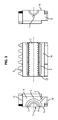
- each shell 1 has on one of its longitudinal faces, called “front face” 1a an impression 2 in which are formed the corrugations 20.
- the face 1b opposite the front face 1a is called “dorsal face”.
- the other two longitudinal faces 1c and 1d (that is to say parallel to the direction of movement of the parison and shells) of the shell are designated by the terms “upper face” and “lower face”.
- the front face 1a of at least one of the shells of each pair has two longitudinal grooves 3 and 4 located on either side of the cavity 2.
- each of these grooves 3 and 4 is blind, that is to say that it is closed at one of its ends 30, 40 and that it opens, at its other end 31, 41, on a transverse face 1e of the shell.
- the blind grooves 3 and 4 are connected to the vacuum circuit via a groove 5, for example of semicircular shape, formed on the transverse face 1e.
- the groove 5 is connected to the vacuum circuit by a groove 6 (not shown on the Figures 1 and 2 but illustrated at the figure 3 ).
- the vacuum circuit of the shell illustrated here is only one of a number of variants. Indeed, other ways to apply depression and plate shells can be used without departing from the scope of the present invention.
- the longitudinal grooves can be blind on both sides and connected to the vacuum circuit by holes in the shell instead of a groove on a transverse face.
- suction slots 21 and 22 are formed at the bottom of each corrugation and open, at each of their ends, in the blind grooves 3 and 4.
- the width of the slits 21 and 22 is determined by those skilled in the art as a function of the material of the conduit.
- the two suction slots 21 and 22 are, for example, arranged at equal distance on either side of the transverse plane of symmetry of each annulus.
- the profile of the corrugations is substantially square, and the suction slots are located in the corners of the corrugations, that is to say in the radius, or even in the recess of the corrugations.
- the suction slots are placed on either side of the top of the corrugation.
- the corrugated pipe thus formed is visually distinguished from a duct formed by blowing in that it comprises, on each annulure, two traces T1, T2 corresponding to suction slots of the shells.
- Figure 4A illustrates the external profile of a corrugated duct formed by depression using the shells of the prior art: there is a trace T located at the top of the annulus.
- this double slot is necessary because of the large width (typically of the order of 8 mm) of the corrugations. Indeed, a single suction slot would be insufficient to allow a good veneer of the parison in each annealing imprint.
- the solution chosen by the Applicant is to form a single suction slot 22 in the last corrugation and to feed it through a bore 7 located on the transverse face 1f.
- the (or) drilling (s) 7 is supplied with vacuum by the groove 5 located on the transverse face 1e of the adjacent shell.
- the second slot is obtained when the face 1f of the shell is brought into contact with the face 1e of the adjacent shell, the impression thereof being slightly withdrawn with respect to the face 1e.
- This second slot is then supplied with vacuum by the longitudinal blind grooves 3 and 4 of the adjacent cavity.
- the ducts may be made of any synthetic material usually used in the intended applications, and in particular the materials belonging to the families of polyolefins (polyethylene, polypropylene, etc.) and polyamides.
- annealed pipes of large diameters and made in double or triple PVC wall exist and are used especially in the field of sanitation.
- PVC is indeed a very pasty and stiff material, which is difficult to form.
- the invention therefore allows the manufacture of corrugated PVC ducts by depression, which opens the possibility of obtaining annealed ducts pre-cased or pre-spun PVC.
- the invention is not limited to annealed ducts having a wall made of a single material, but that it also applies to the manufacture of corrugated pipes with a single wall whose wall consists of a plurality of layers of different materials.
Abstract
Description
La présente invention concerne une coquille pour la fabrication par dépression de conduits annelés, et les conduits annelés fabriqués au moyen d'une telle coquille.The present invention relates to a shell for the vacuum manufacturing of annealed ducts, and corrugated ducts manufactured using such a shell.
Pour la fabrication de conduits annelés de petits diamètres (c'est-à-dire présentant un diamètre extérieur inférieur ou égal à 40 mm), on utilise une installation de formage par dépression comprenant, en sortie d'une extrudeuse, deux chaînes sans fin de coquilles dans laquelle chaque coquille porte l'empreinte de la moitié du conduit.For the manufacture of corrugated conduits of small diameters (that is to say having an outside diameter of less than or equal to 40 mm), a vacuum forming apparatus is used comprising, at the outlet of an extruder, two endless chains. of shells in which each shell bears the imprint of half of the duct.
Le formage par dépression est notamment utilisé pour former des gaines annelées pré-tubées ou pré-filées, c'est-à-dire des gaines dans lesquelles on insère, en même temps qu'elles sont formées, un tube ou un ou plusieurs câbles. De telles gaines trouvent notamment application dans le domaine de l'électricité...Vacuum forming is used in particular to form pre-cased or pre-spunbond corrugated sheaths, that is sheaths into which a tube or one or more cables are inserted at the same time as they are formed. . Such sheaths find particular application in the field of electricity ...
Après formage, le conduit est généralement enroulé sous forme de bobines.After forming, the conduit is generally wound into coils.
Les conduits annelés de petit diamètre présentent des annelures relativement étroites, c'est-à-dire d'une largeur inférieure ou égale à 3 mm, par exemple d'une largeur de l'ordre de 2,5 mm.The annular conduits of small diameter have relatively narrow annular grooves, that is to say with a width less than or equal to 3 mm, for example with a width of the order of 2.5 mm.
Par largeur de l'annelure, on entend la largeur du sommet de celle-ci, c'est-à-dire la longueur du sommet du trapèze dans laquelle est inscrite l'annelure.By width of the annulus, is meant the width of the top thereof, that is to say the length of the vertex of the trapezium in which is inscribed the annealing.
La largeur minimale de l'annelure dépend des contraintes spécifiques à la réalisation du conduit considéré.The minimum width of the corrugation depends on the specific constraints to the realization of the considered pipe.
Pour favoriser le placage de la paraison dans l'empreinte, et notamment au fond de la partie annelée, on ménage, au fond de chaque empreinte d'annelure, une fente d'aspiration reliée au circuit de vide.To promote the veneer of the parison in the cavity, and in particular at the bottom of the corrugated portion, at the bottom of each annealing cavity, there is provided a suction slot connected to the vacuum circuit.
On garantit ainsi que les annelures du conduit obtenu présentent le profil souhaité.It is thus ensured that the corrugations of the duct obtained have the desired profile.
Toutefois, il a été constaté qu'au niveau de la fente, c'est-à-dire au sommet des annelures, il se forme une légère aspérité dont la grosseur est fonction de la fluidité de la matière extrudée. En effet, plus la matière est fluide, plus elle peut s'infiltrer dans la fente et former une aspérité.However, it has been found that at the slot, that is to say at the top of the corrugations, there is a slight asperity whose size is a function of the fluidity of the extruded material. In fact, the more fluid the material, the more it can infiltrate the slot and form an asperity.
Cette aspérité est agressive pour l'utilisateur du conduit, notamment lorsqu'il le débobine de manière prolongée en le faisant glisser entre ses mains.This asperity is aggressive for the user of the conduit, especially when it unwinds for a long time by sliding it between his hands.
Une solution envisageable pour atténuer le relief de l'aspérité serait de travailler avec des matières de viscosité plus élevée, de sorte que la matière ne soit pas susceptible de s'infiltrer dans la fente d'aspiration.A possible solution to reduce the relief of the roughness would be to work with higher viscosity materials, so that the material is not likely to seep into the suction slot.
Toutefois, cette solution s'opérerait au détriment du respect du profil des annelures, puisque la matière se prêterait plus difficilement au formage des annelures.However, this solution would operate to the detriment of the respect of the profile of the corrugations, since the material would lend itself more difficult to the formation of annellations.
On pourrait également envisager d'influer sur la valeur de la dépression, puisqu'une aspiration moins forte permettrait de réduire la quantité de matière s'infiltrant dans la fente.One could also consider influencing the value of depression, since a lower suction would reduce the amount of material seeping into the slot.
Toutefois, il est nécessaire de maintenir une certaine dépression pour former correctement les annelures.However, it is necessary to maintain some depression to properly form the rings.
Il est donc difficile d'ajuster la valeur de la dépression pour répondre à ces deux contraintes.It is therefore difficult to adjust the value of depression to meet these two constraints.
La présente invention a donc pour but d'améliorer le formage par dépression des conduits annelés de petit diamètre, en supprimant toute aspérité susceptible d'irriter l'utilisateur. L'invention vise donc à obtenir des conduits annelés de petit diamètre et/ou présentant des annelures de faible largeur (moins de 3 mm) sur lesquels la trace liée à la fente d'aspiration n'est pas sensible au toucher par l'utilisateur.The object of the present invention is therefore to improve the vacuum forming of small diameter corrugated pipes, by eliminating any roughness likely to irritate the user. The invention therefore aims to obtain corrugated conduits of small diameter and / or having small width corrugations (less than 3 mm) on which the trace linked to the suction slot is not sensitive to the user's touch. .
Un autre but de l'invention est de concevoir un outillage pour former de tels conduits qui soit robuste et fiable.Another object of the invention is to design a tool to form such conduits that is robust and reliable.
Un autre objectif de l'invention est encore de permettre le formage de conduits annelés quel que soit le matériau souhaité.Another object of the invention is to allow the forming of annealed ducts whatever the desired material.
Conformément à l'invention, il est proposé une coquille pour la fabrication par dépression d'un conduit annelé dans une installation de formage comprenant deux chaînes sans fin de coquilles et un circuit de vide, ladite coquille présentant une empreinte pour le formage d'une moitié dudit conduit, ledit conduit présentant un diamètre extérieur inférieur ou égal à 40 mm et/ou les annelures présentant une largeur inférieure ou égale à 3 mm, ladite coquille étant caractérisée en ce que l'empreinte comporte, par annelure, deux fentes d'aspiration reliées au circuit de vide et situées en-deçà du sommet de l'annelure, c'est-à-dire à une distance, par rapport à l'axe du conduit, inférieure au diamètre extérieur de l'annelure.According to the invention, there is provided a shell for the vacuum production of a corrugated conduit in a forming plant comprising two endless chains of shells and a vacuum circuit, said shell having an impression for forming a half of said duct, said duct having an outside diameter less than or equal to 40 mm and / or corrugations having a width less than or equal to 3 mm, said shell being characterized in that the imprint comprises, by annealing, two slots of suction connected to the vacuum circuit and located below the top of the annulus, that is to say at a distance, relative to the axis of the duct, smaller than the outer diameter of the annular groove.
De préférence, les fentes d'aspiration sont disposées de part et d'autre du plan de symétrie de l'annelure passant par le sommet de celle-ci.Preferably, the suction slots are disposed on either side of the plane of symmetry of the corrugation passing through the top thereof.
Selon un mode préféré de réalisation de l'invention, les deux fentes d'aspiration débouchent dans deux rainures longitudinales borgnes situées de part et d'autre de l'empreinte, lesdites rainures borgnes débouchant dans une gorge située sur une face transversale de la coquille et reliée au circuit de vide.According to a preferred embodiment of the invention, the two suction slots open into two blind longitudinal grooves located on either side of the cavity, said blind grooves opening into a groove located on a transverse face of the shell. and connected to the vacuum circuit.
Un autre objet de l'invention concerne un conduit annelé formé par dépression présentant un diamètre extérieur inférieur ou égal à 40 mm et/ou des annelures d'une largeur inférieure ou égale à 3 mm, ledit conduit étant caractérisé en ce que la surface extérieure de chaque annelure présente deux traces correspondant chacune à une fente d'aspiration et situées en-deçà du sommet de l'annelure.Another object of the invention relates to a corrugated duct formed by a depression having an outside diameter less than or equal to 40 mm and / or corrugations of a width less than or equal to 3 mm, said duct being characterized in that the outer surface each annulus has two traces each corresponding to a suction slot and located below the top of the annulus.
De préférence, les traces sont situées de part et d'autre du sommet de l'annelure.Preferably, the traces are located on either side of the top of the annulus.
De manière particulièrement avantageuse, ledit conduit annelé est en PVC.Particularly advantageously, said annealed conduit is made of PVC.
Selon un mode préféré de réalisation, le conduit annelé présente une simple paroi annelée, et il peut renfermer au moins un tube ou un câble (conduit pré-tubé ou pré-filé).According to a preferred embodiment, the annular conduit has a simple corrugated wall, and it can contain at least one tube or cable (pre-tubed or pre-spun conduit).
L'invention concerne en outre un procédé de fabrication par dépression d'un conduit annelé présentant un diamètre extérieur inférieur ou égal à 40 mm et/ou des annelures d'une largeur inférieure ou égale à 3 mm, ledit procédé étant caractérisé en ce que l'on utilise, dans une installation comportant deux chaînes sans fin de coquilles et un circuit de vide, des coquilles telles que décrites plus haut.The invention furthermore relates to a vacuum manufacturing method of a corrugated duct having an outside diameter less than or equal to 40 mm and / or corrugations with a width of less than or equal to 3 mm, said method being characterized in that, in an installation comprising two endless chains of shells and a vacuum circuit, shells as described above are used.
De manière particulièrement avantageuse, lors de la fabrication dudit conduit annelé, on insère dans celui-ci au moins un tube ou un câble.Particularly advantageously, during the manufacture of said corrugated conduit is inserted into it at least one tube or cable.
D'autres caractéristiques et avantages de l'invention ressortiront de la description détaillée qui va suivre, en référence aux dessins annexés sur lesquels :
- les
figures 1 et 2 sont des vues en perspective d'une coquille conforme à l'invention ; - la
figure 3 présente des vues de face et de côté de ladite coquille ; - les
figures 4A et 4B illustrent respectivement, de manière grossie, le profil extérieur d'un conduit annelé formé par dépression conformément à l'art antérieur et le profil extérieur d'un conduit annelé formé par dépression conformément à l'invention.
- the
Figures 1 and 2 are perspective views of a shell according to the invention; - the
figure 3 has front and side views of said shell; - the
Figures 4A and 4B respectively illustrate, magnified, the outer profile of a corrugated duct formed by depression in accordance with the prior art and the outer profile of a corrugated duct formed by depression according to the invention.
L'installation de formage par dépression de conduits annelés est connue et ne sera donc pas décrite en détail.The annealed duct vacuum forming plant is known and will therefore not be described in detail.
Une telle installation est par exemple décrite dans le brevet
L'installation comporte deux chaînes sans fin de coquilles généralement prismatiques, articulées entre elles et se faisant face par paires. Elle comporte par ailleurs un circuit de vide permettant de générer une dépression à l'intérieur des coquilles.The installation comprises two endless chains of generally prismatic shells hinged together and facing each other in pairs. It also comprises a vacuum circuit for generating a vacuum inside the shells.
Cette installation est disposée à la sortie d'une extrudeuse qui extrude une paraison en matériau synthétique, typiquement un thermoplastique.This installation is disposed at the outlet of an extruder which extrudes a parison made of synthetic material, typically a thermoplastic.
En référence à la
Les deux autres faces longitudinales 1c et 1d (c'est-à-dire parallèles à la direction de déplacement de la paraison et des coquilles) de la coquille sont désignées par les termes de « face supérieure » et « face inférieure ».The other two
La face avant 1a d'au moins une des coquilles de chaque paire comporte deux rainures longitudinales 3 et 4 situées de part et d'autre de l'empreinte 2.The
De préférence, chacune de ces rainures 3 et 4 est borgne c'est-à-dire qu'elle est fermée à l'une de ses extrémités 30, 40 et qu'elle débouche, à son autre extrémité 31, 41, sur une face transversale 1e de la coquille.Preferably, each of these
Les rainures borgnes 3 et 4 sont reliées au circuit de vide par l'intermédiaire d'une gorge 5, par exemple de forme semi-circulaire, ménagée sur la face transversale 1e. La gorge 5 est reliée au circuit de vide par une rainure 6 (non représentée sur les
Comme expliqué dans le brevet
Toutefois, il va de soi que le circuit de vide de la coquille illustré ici n'est qu'un exemple préféré parmi de nombreuses variantes. En effet, d'autres moyens pour appliquer la dépression et plaquer les coquilles peuvent être employés sans pour autant sortir du cadre de la présente invention. Ainsi, par exemple, les rainures longitudinales peuvent être borgnes des deux côtés et reliées au circuit de vide par des perçages à l'intérieur de la coquille au lieu d'une rainure sur une face transversale.However, it goes without saying that the vacuum circuit of the shell illustrated here is only one of a number of variants. Indeed, other ways to apply depression and plate shells can be used without departing from the scope of the present invention. Thus, for example, the longitudinal grooves can be blind on both sides and connected to the vacuum circuit by holes in the shell instead of a groove on a transverse face.
Dans l'empreinte 2, deux fentes d'aspiration 21 et 22 sont formées au fond de chaque annelure et débouchent, à chacune de leurs extrémités, dans les rainures borgnes 3 et 4.In the
La largeur des fentes 21 et 22 est déterminée par l'homme du métier en fonction du matériau du conduit.The width of the
Les deux fentes d'aspiration 21 et 22 sont, par exemple, disposées à égale distance de part et d'autre du plan de symétrie transversal de chaque annelure.The two
Sur les figures présentées ici, le profil des annelures est sensiblement carré, et les fentes d'aspiration sont situées dans les coins des annelures, c'est-à-dire dans le rayon, voire dans la dépouille des annelures.In the figures presented here, the profile of the corrugations is substantially square, and the suction slots are located in the corners of the corrugations, that is to say in the radius, or even in the recess of the corrugations.
Dans le cas d'annelures au profil plus arrondi, on place les fentes d'aspiration de part et d'autre du sommet de l'annelure.In the case of corrugations with a more rounded profile, the suction slots are placed on either side of the top of the corrugation.
Ainsi, dans tous les cas, même si de légères aspérités se forment au niveau de ces fentes, elles se trouvent en retrait par rapport au sommet de l'annelure et ne risquent pas de blesser l'opérateur lors de la manipulation du conduit.Thus, in all cases, even if slight asperities are formed at these slots, they are set back from the top of the corrugation and do not risk to injure the operator during the handling of the conduit.
On peut ainsi utiliser une matière fluide et/ou une dépression élevée sans que cela ne se traduise par des aspérités inconfortables pour l'utilisateur.It is thus possible to use a fluid material and / or a high vacuum without this resulting in uncomfortable asperities for the user.
En référence à la
Au contraire, un conduit formé par soufflage ne comporte pas de trace au niveau des annelures.On the contrary, a duct formed by blowing does not have any trace at the level of the corrugations.
A titre de comparaison, la
On précise que pour la fabrication de conduits annelés de type double paroi et de gros diamètres (c'est-à-dire présentant typiquement un diamètre extérieur supérieur à 40 mm), il est connu de placer deux fentes d'aspiration de part et d'autre du sommet de chaque annelure.It is specified that for the manufacture of annealed ducts of double wall type and large diameters (that is to say typically having an outside diameter greater than 40 mm), it is known to place two suction slots on both sides. other from the top of each annelure.
Toutefois, sur ces conduits particuliers, cette double fente est nécessaire en raison de la largeur importante (typiquement, de l'ordre de 8 mm) des annelures. En effet, une fente d'aspiration unique serait insuffisante pour permettre un bon placage de la paraison dans chaque empreinte d'annelure.However, on these particular ducts, this double slot is necessary because of the large width (typically of the order of 8 mm) of the corrugations. Indeed, a single suction slot would be insufficient to allow a good veneer of the parison in each annealing imprint.
Un problème particulier se pose pour l'alimentation en vide de la dernière annelure, c'est-à-dire celle située à l'extrémité de la coquille opposée à la face transversale 1e dans laquelle débouchent les rainures longitudinales borgnes 3 et 4.A particular problem arises for the vacuum supply of the last corrugation, that is to say that located at the end of the shell opposite to the
En effet, dans la mesure où les rainures longitudinales 3 et 4 sont borgnes, il n'y a pas de rainure longitudinale en face de la dernière annelure.Indeed, insofar as the
Pour relier la fente d'aspiration de cette empreinte au circuit de vide, il serait donc nécessaire de créer deux rainures longitudinales borgnes, alignées avec les rainures borgnes 3 et 4, de part et d'autre de la dernière annelure. Ces rainures borgnes supplémentaires présenteraient une extrémité borgne située à proximité de l'extrémité borgne 30, 40 des rainures 3 et 4 et déboucheraient, à leur extrémité opposée, sur la face transversale 1f opposée à la face 1e de la coquille. De la sorte, ces rainures seraient reliées au circuit de vide par l'intermédiaire de la gorge 5 de la face transversale 1e de la coquille adjacente.To connect the suction slot of this cavity to the vacuum circuit, it would therefore be necessary to create two blind longitudinal grooves, aligned with the
Or, il serait très délicat d'usiner ces rainures borgnes sur une longueur aussi courte, en veillant à ce qu'elles ne débouchent pas dans les rainures borgnes 3 et 4.However, it would be very difficult to machine these blind grooves on such a short length, ensuring that they do not open into the
La solution retenue par la Demanderesse consiste à former une unique fente d'aspiration 22 dans la dernière annelure et à l'alimenter par un perçage 7 situé sur la face transversale 1f.The solution chosen by the Applicant is to form a
On précise que, sur la
Le (ou les) perçage(s) 7 est alimenté en vide par la gorge 5 située sur la face transversale 1e de la coquille adjacente.The (or) drilling (s) 7 is supplied with vacuum by the
Pour cette dernière annelure, la deuxième fente est obtenue lors de la mise en contact de la face 1f de la coquille avec la face 1e de la coquille adjacente, l'empreinte de celle-ci étant en léger retrait par rapport à la face 1e. Cette deuxième fente est alors alimentée en vide par les rainures longitudinales borgnes 3 et 4 de l'empreinte adjacente.For this last annealing, the second slot is obtained when the
Les conduits peuvent être réalisés en tout matériau synthétique habituellement utilisé dans les applications visées, et notamment les matériaux appartenant aux familles des polyoléfines (polyéthylène, polypropylène...) et des polyamides.The ducts may be made of any synthetic material usually used in the intended applications, and in particular the materials belonging to the families of polyolefins (polyethylene, polypropylene, etc.) and polyamides.
La Demanderesse a par ailleurs constaté que, de manière inattendue, les coquilles qui viennent d'être décrites permettent de former par dépression des conduits annelés en PVC de petit diamètre.The Applicant has moreover found that, unexpectedly, the shells which have just been described make it possible to form annular conduits of small diameter PVC by depression.
En effet, les conduits annelés de gros diamètres et réalisés en double ou triple paroi PVC, existent et sont employés notamment dans le domaine de l'assainissement.Indeed, annealed pipes of large diameters and made in double or triple PVC wall, exist and are used especially in the field of sanitation.
En revanche, pour former des conduits annelés de petit diamètre en PVC, il n'était possible que de procéder par soufflage et les tentatives de former de tels conduits par dépression au moyen des coquilles connues présentant une fente d'aspiration au sommet de l'annelure avaient échoué.On the other hand, in order to form annular conduits of small diameter in PVC, it was only possible to proceed by blowing and the attempts to form such ducts by depression by means of known shells having a suction slot at the top of the tube. annealing had failed.
Le PVC est en effet une matière très pâteuse et raide, qui se prête difficilement au formage.PVC is indeed a very pasty and stiff material, which is difficult to form.
L'invention permet donc la fabrication de conduits annelés en PVC par dépression, ce qui ouvre la possibilité d'obtenir des gaines annelées pré-tubées ou pré-filées en PVC.The invention therefore allows the manufacture of corrugated PVC ducts by depression, which opens the possibility of obtaining annealed ducts pre-cased or pre-spun PVC.
On précise enfin que l'invention n'est pas limitée à des conduits annelés présentant une paroi constituée d'un matériau unique, mais qu'elle s'applique également à la fabrication de conduits annelés à simple paroi dont la paroi se compose d'une pluralité de couches de matériaux différents.Finally, it is specified that the invention is not limited to annealed ducts having a wall made of a single material, but that it also applies to the manufacture of corrugated pipes with a single wall whose wall consists of a plurality of layers of different materials.
Claims (10)
Applications Claiming Priority (1)
| Application Number | Priority Date | Filing Date | Title |
|---|---|---|---|
| FR0952259A FR2943940B1 (en) | 2009-04-07 | 2009-04-07 | SHELL FOR MANUFACTURING BY LOW PRESSURE DRAWINGS. |
Publications (2)
| Publication Number | Publication Date |
|---|---|
| EP2239126A1 true EP2239126A1 (en) | 2010-10-13 |
| EP2239126B1 EP2239126B1 (en) | 2011-10-26 |
Family
ID=41665162
Family Applications (1)
| Application Number | Title | Priority Date | Filing Date |
|---|---|---|---|
| EP10158369A Not-in-force EP2239126B1 (en) | 2009-04-07 | 2010-03-30 | Mould for vacuum moulding a corrugated pipe, manufactured pipe and method |
Country Status (4)
| Country | Link |
|---|---|
| EP (1) | EP2239126B1 (en) |
| AT (1) | ATE530324T1 (en) |
| ES (1) | ES2372919T3 (en) |
| FR (1) | FR2943940B1 (en) |
Cited By (2)
| Publication number | Priority date | Publication date | Assignee | Title |
|---|---|---|---|---|
| CN103072226A (en) * | 2013-02-07 | 2013-05-01 | 詹春生 | Forming module for double-wall corrugated pipeline |
| CN104118081A (en) * | 2014-01-24 | 2014-10-29 | 苏州杰威尔精密机械有限公司 | Corrugated pipe forming module |
Citations (7)
| Publication number | Priority date | Publication date | Assignee | Title |
|---|---|---|---|---|
| US4248459A (en) * | 1978-02-06 | 1981-02-03 | Indian Head Inc. | Flexible conduit system |
| EP0435446A2 (en) * | 1989-12-26 | 1991-07-03 | CULLOM MACHINE TOOL & DIE, INC. | Corrugated mold block |
| EP0563575A2 (en) * | 1992-03-31 | 1993-10-06 | Wilhelm Hegler | Method and apparatus for continuous production of a composite pipe with sleeve |
| FR2748417A1 (en) | 1996-05-09 | 1997-11-14 | Corelco | Vacuum application in continuous vacuum forming of tubular synthetic parts |
| US6142188A (en) * | 1999-10-29 | 2000-11-07 | Dayco Products, Inc. | Corrugated flexible hose |
| DE20116058U1 (en) * | 2001-09-29 | 2003-02-13 | Unicor Rohrsysteme Gmbh | Half shell tool for production of transverse corrugated pipes has inserts mounted in recesses in a base surface of a half shell and fastened by a screw between recesses on both half shell and insert |
| US20040007278A1 (en) * | 2002-06-06 | 2004-01-15 | Williams Robert M. | Flexible conduit and method for forming the same |
-
2009
- 2009-04-07 FR FR0952259A patent/FR2943940B1/en not_active Expired - Fee Related
-
2010
- 2010-03-30 AT AT10158369T patent/ATE530324T1/en not_active IP Right Cessation
- 2010-03-30 EP EP10158369A patent/EP2239126B1/en not_active Not-in-force
- 2010-03-30 ES ES10158369T patent/ES2372919T3/en active Active
Patent Citations (7)
| Publication number | Priority date | Publication date | Assignee | Title |
|---|---|---|---|---|
| US4248459A (en) * | 1978-02-06 | 1981-02-03 | Indian Head Inc. | Flexible conduit system |
| EP0435446A2 (en) * | 1989-12-26 | 1991-07-03 | CULLOM MACHINE TOOL & DIE, INC. | Corrugated mold block |
| EP0563575A2 (en) * | 1992-03-31 | 1993-10-06 | Wilhelm Hegler | Method and apparatus for continuous production of a composite pipe with sleeve |
| FR2748417A1 (en) | 1996-05-09 | 1997-11-14 | Corelco | Vacuum application in continuous vacuum forming of tubular synthetic parts |
| US6142188A (en) * | 1999-10-29 | 2000-11-07 | Dayco Products, Inc. | Corrugated flexible hose |
| DE20116058U1 (en) * | 2001-09-29 | 2003-02-13 | Unicor Rohrsysteme Gmbh | Half shell tool for production of transverse corrugated pipes has inserts mounted in recesses in a base surface of a half shell and fastened by a screw between recesses on both half shell and insert |
| US20040007278A1 (en) * | 2002-06-06 | 2004-01-15 | Williams Robert M. | Flexible conduit and method for forming the same |
Cited By (3)
| Publication number | Priority date | Publication date | Assignee | Title |
|---|---|---|---|---|
| CN103072226A (en) * | 2013-02-07 | 2013-05-01 | 詹春生 | Forming module for double-wall corrugated pipeline |
| CN103072226B (en) * | 2013-02-07 | 2016-01-13 | 詹春生 | A kind of double-wall corrugated pipeline forming module |
| CN104118081A (en) * | 2014-01-24 | 2014-10-29 | 苏州杰威尔精密机械有限公司 | Corrugated pipe forming module |
Also Published As
| Publication number | Publication date |
|---|---|
| FR2943940A1 (en) | 2010-10-08 |
| ES2372919T3 (en) | 2012-01-27 |
| ATE530324T1 (en) | 2011-11-15 |
| FR2943940B1 (en) | 2011-04-22 |
| EP2239126B1 (en) | 2011-10-26 |
Similar Documents
| Publication | Publication Date | Title |
|---|---|---|
| EP0027252B1 (en) | Apparatus for manufacturing ceramic honeycomb structures by extrusion and method of manufacturing this apparatus | |
| CA2675732C (en) | Method for producing a multi-layered object | |
| EP2239126B1 (en) | Mould for vacuum moulding a corrugated pipe, manufactured pipe and method | |
| EP0637504A2 (en) | Tyre mould and process for moulding tyres | |
| EP2072287B1 (en) | Tyre, mould for vulcanisation of said tyre, method for manufacturing said mould and mould plate | |
| EP1089411B1 (en) | Device intended to be pierced by a cylindrical object in a sealed condition, box for electrical apparatus and a process using these | |
| FR3017178A1 (en) | ANNELED TUBULAR SHEATH WITH INTERNAL CLAMPING MEANS | |
| EP0707934B1 (en) | Venting moulds | |
| EP1630829B1 (en) | Apparatus for manufacture of an alveolar sheath around a conductor | |
| EP3168029A1 (en) | Extrusion tool; process of manufacturing and method of using the tool | |
| FR2991519A1 (en) | ELECTRICAL BOX COMPRISING A SHEATH INLET DEVICE | |
| EP2222450A1 (en) | Device and method for producing a tread | |
| EP2026401B1 (en) | Method of manufacturing a manifold for a fuel cell system, manifold and system obtained through said process | |
| EP3558624B1 (en) | Extrusion equipment comprising an improved extrusion head | |
| EP1891491B1 (en) | Method of producing a part by decomposition into layers, said part having fluid transfer channels extending through the interlayers thereof | |
| EP1144901B1 (en) | Device for connecting a branch pipe on a fluid-transporting piping system | |
| WO2020021369A1 (en) | Method for producing a molding element having an air discharge slot | |
| FR2877259A1 (en) | Moulding device for manufacturing envelope of heicoidal bellows comprises a mould and core having complementary threading to delimit moulding space and the envelope and core are unscrewed for stripping of the envelope | |
| FR2881982A1 (en) | Connecting device e.g. bent bundle duct/cable grommet, for passage and protection of electric cables, has inserts situated at ends of flexible body that has part presenting spiral shape in accordion, where body and inserts form single block | |
| EP4330583A1 (en) | Connection device bent at multiple angles | |
| WO2006048433A1 (en) | Device for producing, by molding, a casing with bellows having means for holding an unscrewable core, and corresponding method | |
| FR3102338A1 (en) | Cheese mold, in particular for cheese of the county type, and method of making such a mold | |
| FR2954012A1 (en) | Ringed sheath for passage of cable i.e. electric wire, in building field, has oblong section in which height of rings varies between minimal height in zone having smaller dimension and maximum height in zone having larger dimension | |
| FR2881679A1 (en) | Envelope molding device comprises printing mold, truncated core to carry out the unmolding of the envelope and maintenance for allowing a relative unscrewing of the envelope | |
| WO2011076676A1 (en) | Tyre tread having cavities and incisions |
Legal Events
| Date | Code | Title | Description |
|---|---|---|---|
| PUAI | Public reference made under article 153(3) epc to a published international application that has entered the european phase |
Free format text: ORIGINAL CODE: 0009012 |
|
| AK | Designated contracting states |
Kind code of ref document: A1 Designated state(s): AT BE BG CH CY CZ DE DK EE ES FI FR GB GR HR HU IE IS IT LI LT LU LV MC MK MT NL NO PL PT RO SE SI SK SM TR |
|
| AX | Request for extension of the european patent |
Extension state: AL BA ME RS |
|
| 17P | Request for examination filed |
Effective date: 20110302 |
|
| RIC1 | Information provided on ipc code assigned before grant |
Ipc: B29C 49/00 20060101ALI20110318BHEP Ipc: F16L 11/11 20060101ALI20110318BHEP Ipc: B29C 47/12 20060101AFI20110318BHEP |
|
| GRAP | Despatch of communication of intention to grant a patent |
Free format text: ORIGINAL CODE: EPIDOSNIGR1 |
|
| RTI1 | Title (correction) |
Free format text: MOULD FOR VACUUM MOULDING A CORRUGATED PIPE, MANUFACTURED PIPE AND METHOD |
|
| GRAS | Grant fee paid |
Free format text: ORIGINAL CODE: EPIDOSNIGR3 |
|
| GRAA | (expected) grant |
Free format text: ORIGINAL CODE: 0009210 |
|
| AK | Designated contracting states |
Kind code of ref document: B1 Designated state(s): AT BE BG CH CY CZ DE DK EE ES FI FR GB GR HR HU IE IS IT LI LT LU LV MC MK MT NL NO PL PT RO SE SI SK SM TR |
|
| REG | Reference to a national code |
Ref country code: GB Ref legal event code: FG4D Free format text: NOT ENGLISH |
|
| REG | Reference to a national code |
Ref country code: CH Ref legal event code: EP |
|
| REG | Reference to a national code |
Ref country code: IE Ref legal event code: FG4D |
|
| REG | Reference to a national code |
Ref country code: DE Ref legal event code: R096 Ref document number: 602010000304 Country of ref document: DE Effective date: 20120105 |
|
| REG | Reference to a national code |
Ref country code: ES Ref legal event code: FG2A Ref document number: 2372919 Country of ref document: ES Kind code of ref document: T3 Effective date: 20120127 |
|
| REG | Reference to a national code |
Ref country code: NL Ref legal event code: VDEP Effective date: 20111026 |
|
| LTIE | Lt: invalidation of european patent or patent extension |
Effective date: 20111026 |
|
| REG | Reference to a national code |
Ref country code: AT Ref legal event code: MK05 Ref document number: 530324 Country of ref document: AT Kind code of ref document: T Effective date: 20111026 |
|
| PG25 | Lapsed in a contracting state [announced via postgrant information from national office to epo] |
Ref country code: NO Free format text: LAPSE BECAUSE OF FAILURE TO SUBMIT A TRANSLATION OF THE DESCRIPTION OR TO PAY THE FEE WITHIN THE PRESCRIBED TIME-LIMIT Effective date: 20120126 Ref country code: LT Free format text: LAPSE BECAUSE OF FAILURE TO SUBMIT A TRANSLATION OF THE DESCRIPTION OR TO PAY THE FEE WITHIN THE PRESCRIBED TIME-LIMIT Effective date: 20111026 Ref country code: IS Free format text: LAPSE BECAUSE OF FAILURE TO SUBMIT A TRANSLATION OF THE DESCRIPTION OR TO PAY THE FEE WITHIN THE PRESCRIBED TIME-LIMIT Effective date: 20120226 |
|
| PG25 | Lapsed in a contracting state [announced via postgrant information from national office to epo] |
Ref country code: GR Free format text: LAPSE BECAUSE OF FAILURE TO SUBMIT A TRANSLATION OF THE DESCRIPTION OR TO PAY THE FEE WITHIN THE PRESCRIBED TIME-LIMIT Effective date: 20120127 Ref country code: SE Free format text: LAPSE BECAUSE OF FAILURE TO SUBMIT A TRANSLATION OF THE DESCRIPTION OR TO PAY THE FEE WITHIN THE PRESCRIBED TIME-LIMIT Effective date: 20111026 Ref country code: SI Free format text: LAPSE BECAUSE OF FAILURE TO SUBMIT A TRANSLATION OF THE DESCRIPTION OR TO PAY THE FEE WITHIN THE PRESCRIBED TIME-LIMIT Effective date: 20111026 Ref country code: HR Free format text: LAPSE BECAUSE OF FAILURE TO SUBMIT A TRANSLATION OF THE DESCRIPTION OR TO PAY THE FEE WITHIN THE PRESCRIBED TIME-LIMIT Effective date: 20111026 Ref country code: NL Free format text: LAPSE BECAUSE OF FAILURE TO SUBMIT A TRANSLATION OF THE DESCRIPTION OR TO PAY THE FEE WITHIN THE PRESCRIBED TIME-LIMIT Effective date: 20111026 Ref country code: PL Free format text: LAPSE BECAUSE OF FAILURE TO SUBMIT A TRANSLATION OF THE DESCRIPTION OR TO PAY THE FEE WITHIN THE PRESCRIBED TIME-LIMIT Effective date: 20111026 Ref country code: PT Free format text: LAPSE BECAUSE OF FAILURE TO SUBMIT A TRANSLATION OF THE DESCRIPTION OR TO PAY THE FEE WITHIN THE PRESCRIBED TIME-LIMIT Effective date: 20120227 Ref country code: LV Free format text: LAPSE BECAUSE OF FAILURE TO SUBMIT A TRANSLATION OF THE DESCRIPTION OR TO PAY THE FEE WITHIN THE PRESCRIBED TIME-LIMIT Effective date: 20111026 |
|
| REG | Reference to a national code |
Ref country code: IE Ref legal event code: FD4D |
|
| PG25 | Lapsed in a contracting state [announced via postgrant information from national office to epo] |
Ref country code: CY Free format text: LAPSE BECAUSE OF FAILURE TO SUBMIT A TRANSLATION OF THE DESCRIPTION OR TO PAY THE FEE WITHIN THE PRESCRIBED TIME-LIMIT Effective date: 20111026 |
|
| PG25 | Lapsed in a contracting state [announced via postgrant information from national office to epo] |
Ref country code: CZ Free format text: LAPSE BECAUSE OF FAILURE TO SUBMIT A TRANSLATION OF THE DESCRIPTION OR TO PAY THE FEE WITHIN THE PRESCRIBED TIME-LIMIT Effective date: 20111026 Ref country code: IE Free format text: LAPSE BECAUSE OF FAILURE TO SUBMIT A TRANSLATION OF THE DESCRIPTION OR TO PAY THE FEE WITHIN THE PRESCRIBED TIME-LIMIT Effective date: 20111026 Ref country code: BG Free format text: LAPSE BECAUSE OF FAILURE TO SUBMIT A TRANSLATION OF THE DESCRIPTION OR TO PAY THE FEE WITHIN THE PRESCRIBED TIME-LIMIT Effective date: 20120126 Ref country code: SK Free format text: LAPSE BECAUSE OF FAILURE TO SUBMIT A TRANSLATION OF THE DESCRIPTION OR TO PAY THE FEE WITHIN THE PRESCRIBED TIME-LIMIT Effective date: 20111026 Ref country code: EE Free format text: LAPSE BECAUSE OF FAILURE TO SUBMIT A TRANSLATION OF THE DESCRIPTION OR TO PAY THE FEE WITHIN THE PRESCRIBED TIME-LIMIT Effective date: 20111026 Ref country code: DK Free format text: LAPSE BECAUSE OF FAILURE TO SUBMIT A TRANSLATION OF THE DESCRIPTION OR TO PAY THE FEE WITHIN THE PRESCRIBED TIME-LIMIT Effective date: 20111026 |
|
| PG25 | Lapsed in a contracting state [announced via postgrant information from national office to epo] |
Ref country code: RO Free format text: LAPSE BECAUSE OF FAILURE TO SUBMIT A TRANSLATION OF THE DESCRIPTION OR TO PAY THE FEE WITHIN THE PRESCRIBED TIME-LIMIT Effective date: 20111026 |
|
| PLBE | No opposition filed within time limit |
Free format text: ORIGINAL CODE: 0009261 |
|
| STAA | Information on the status of an ep patent application or granted ep patent |
Free format text: STATUS: NO OPPOSITION FILED WITHIN TIME LIMIT |
|
| 26N | No opposition filed |
Effective date: 20120727 |
|
| PG25 | Lapsed in a contracting state [announced via postgrant information from national office to epo] |
Ref country code: MC Free format text: LAPSE BECAUSE OF NON-PAYMENT OF DUE FEES Effective date: 20120331 |
|
| REG | Reference to a national code |
Ref country code: DE Ref legal event code: R097 Ref document number: 602010000304 Country of ref document: DE Effective date: 20120727 |
|
| REG | Reference to a national code |
Ref country code: DE Ref legal event code: R082 Ref document number: 602010000304 Country of ref document: DE Representative=s name: KILIAN KILIAN & PARTNER, DE Ref country code: DE Ref legal event code: R082 Ref document number: 602010000304 Country of ref document: DE Representative=s name: KILIAN KILIAN & PARTNER MBB PATENTANWAELTE, DE |
|
| PG25 | Lapsed in a contracting state [announced via postgrant information from national office to epo] |
Ref country code: AT Free format text: LAPSE BECAUSE OF FAILURE TO SUBMIT A TRANSLATION OF THE DESCRIPTION OR TO PAY THE FEE WITHIN THE PRESCRIBED TIME-LIMIT Effective date: 20111026 |
|
| PG25 | Lapsed in a contracting state [announced via postgrant information from national office to epo] |
Ref country code: MK Free format text: LAPSE BECAUSE OF FAILURE TO SUBMIT A TRANSLATION OF THE DESCRIPTION OR TO PAY THE FEE WITHIN THE PRESCRIBED TIME-LIMIT Effective date: 20111026 |
|
| PG25 | Lapsed in a contracting state [announced via postgrant information from national office to epo] |
Ref country code: FI Free format text: LAPSE BECAUSE OF FAILURE TO SUBMIT A TRANSLATION OF THE DESCRIPTION OR TO PAY THE FEE WITHIN THE PRESCRIBED TIME-LIMIT Effective date: 20111026 |
|
| PG25 | Lapsed in a contracting state [announced via postgrant information from national office to epo] |
Ref country code: MT Free format text: LAPSE BECAUSE OF FAILURE TO SUBMIT A TRANSLATION OF THE DESCRIPTION OR TO PAY THE FEE WITHIN THE PRESCRIBED TIME-LIMIT Effective date: 20111026 |
|
| PG25 | Lapsed in a contracting state [announced via postgrant information from national office to epo] |
Ref country code: TR Free format text: LAPSE BECAUSE OF FAILURE TO SUBMIT A TRANSLATION OF THE DESCRIPTION OR TO PAY THE FEE WITHIN THE PRESCRIBED TIME-LIMIT Effective date: 20111026 |
|
| PG25 | Lapsed in a contracting state [announced via postgrant information from national office to epo] |
Ref country code: LU Free format text: LAPSE BECAUSE OF NON-PAYMENT OF DUE FEES Effective date: 20120330 Ref country code: SM Free format text: LAPSE BECAUSE OF FAILURE TO SUBMIT A TRANSLATION OF THE DESCRIPTION OR TO PAY THE FEE WITHIN THE PRESCRIBED TIME-LIMIT Effective date: 20111026 |
|
| PG25 | Lapsed in a contracting state [announced via postgrant information from national office to epo] |
Ref country code: HU Free format text: LAPSE BECAUSE OF FAILURE TO SUBMIT A TRANSLATION OF THE DESCRIPTION OR TO PAY THE FEE WITHIN THE PRESCRIBED TIME-LIMIT Effective date: 20100330 |
|
| REG | Reference to a national code |
Ref country code: CH Ref legal event code: PL |
|
| GBPC | Gb: european patent ceased through non-payment of renewal fee |
Effective date: 20140330 |
|
| PG25 | Lapsed in a contracting state [announced via postgrant information from national office to epo] |
Ref country code: CH Free format text: LAPSE BECAUSE OF NON-PAYMENT OF DUE FEES Effective date: 20140331 Ref country code: GB Free format text: LAPSE BECAUSE OF NON-PAYMENT OF DUE FEES Effective date: 20140330 Ref country code: LI Free format text: LAPSE BECAUSE OF NON-PAYMENT OF DUE FEES Effective date: 20140331 |
|
| REG | Reference to a national code |
Ref country code: FR Ref legal event code: PLFP Year of fee payment: 7 |
|
| REG | Reference to a national code |
Ref country code: FR Ref legal event code: PLFP Year of fee payment: 8 |
|
| REG | Reference to a national code |
Ref country code: FR Ref legal event code: PLFP Year of fee payment: 9 |
|
| REG | Reference to a national code |
Ref country code: DE Ref legal event code: R079 Ref document number: 602010000304 Country of ref document: DE Free format text: PREVIOUS MAIN CLASS: B29C0047120000 Ipc: B29C0048300000 |
|
| PGFP | Annual fee paid to national office [announced via postgrant information from national office to epo] |
Ref country code: FR Payment date: 20190312 Year of fee payment: 10 Ref country code: IT Payment date: 20190314 Year of fee payment: 10 |
|
| PGFP | Annual fee paid to national office [announced via postgrant information from national office to epo] |
Ref country code: DE Payment date: 20190415 Year of fee payment: 10 Ref country code: ES Payment date: 20190517 Year of fee payment: 10 |
|
| PGFP | Annual fee paid to national office [announced via postgrant information from national office to epo] |
Ref country code: BE Payment date: 20190329 Year of fee payment: 10 |
|
| REG | Reference to a national code |
Ref country code: DE Ref legal event code: R119 Ref document number: 602010000304 Country of ref document: DE |
|
| REG | Reference to a national code |
Ref country code: BE Ref legal event code: MM Effective date: 20200331 |
|
| PG25 | Lapsed in a contracting state [announced via postgrant information from national office to epo] |
Ref country code: DE Free format text: LAPSE BECAUSE OF NON-PAYMENT OF DUE FEES Effective date: 20201001 Ref country code: FR Free format text: LAPSE BECAUSE OF NON-PAYMENT OF DUE FEES Effective date: 20200331 |
|
| PG25 | Lapsed in a contracting state [announced via postgrant information from national office to epo] |
Ref country code: BE Free format text: LAPSE BECAUSE OF NON-PAYMENT OF DUE FEES Effective date: 20200331 |
|
| REG | Reference to a national code |
Ref country code: ES Ref legal event code: FD2A Effective date: 20210811 |
|
| PG25 | Lapsed in a contracting state [announced via postgrant information from national office to epo] |
Ref country code: IT Free format text: LAPSE BECAUSE OF NON-PAYMENT OF DUE FEES Effective date: 20200330 |
|
| PG25 | Lapsed in a contracting state [announced via postgrant information from national office to epo] |
Ref country code: ES Free format text: LAPSE BECAUSE OF NON-PAYMENT OF DUE FEES Effective date: 20200331 |