EP2238810B1 - Thermal management of leds integrated to compact fluorescent lamps - Google Patents
Thermal management of leds integrated to compact fluorescent lamps Download PDFInfo
- Publication number
- EP2238810B1 EP2238810B1 EP08871677A EP08871677A EP2238810B1 EP 2238810 B1 EP2238810 B1 EP 2238810B1 EP 08871677 A EP08871677 A EP 08871677A EP 08871677 A EP08871677 A EP 08871677A EP 2238810 B1 EP2238810 B1 EP 2238810B1
- Authority
- EP
- European Patent Office
- Prior art keywords
- light
- led
- base
- light guide
- discharge tube
- Prior art date
- Legal status (The legal status is an assumption and is not a legal conclusion. Google has not performed a legal analysis and makes no representation as to the accuracy of the status listed.)
- Not-in-force
Links
- 239000002184 metal Substances 0.000 claims description 8
- 239000000203 mixture Substances 0.000 abstract description 2
- 239000004033 plastic Substances 0.000 description 9
- 238000009877 rendering Methods 0.000 description 7
- 230000005540 biological transmission Effects 0.000 description 4
- 239000004020 conductor Substances 0.000 description 4
- 230000007423 decrease Effects 0.000 description 4
- 239000011521 glass Substances 0.000 description 4
- 239000011248 coating agent Substances 0.000 description 3
- 238000000576 coating method Methods 0.000 description 3
- 230000008878 coupling Effects 0.000 description 3
- 238000010168 coupling process Methods 0.000 description 3
- 238000005859 coupling reaction Methods 0.000 description 3
- 230000001965 increasing effect Effects 0.000 description 3
- 238000012423 maintenance Methods 0.000 description 3
- 239000000463 material Substances 0.000 description 3
- 229910001369 Brass Inorganic materials 0.000 description 2
- OAICVXFJPJFONN-UHFFFAOYSA-N Phosphorus Chemical compound [P] OAICVXFJPJFONN-UHFFFAOYSA-N 0.000 description 2
- 239000010951 brass Substances 0.000 description 2
- 239000003086 colorant Substances 0.000 description 2
- 230000003287 optical effect Effects 0.000 description 2
- 229920001296 polysiloxane Polymers 0.000 description 2
- 230000015556 catabolic process Effects 0.000 description 1
- 238000005253 cladding Methods 0.000 description 1
- 238000004891 communication Methods 0.000 description 1
- 238000006731 degradation reaction Methods 0.000 description 1
- 230000002708 enhancing effect Effects 0.000 description 1
- 239000012212 insulator Substances 0.000 description 1
- 230000007774 longterm Effects 0.000 description 1
- 238000012986 modification Methods 0.000 description 1
- 230000004048 modification Effects 0.000 description 1
- 230000005855 radiation Effects 0.000 description 1
- 229920002379 silicone rubber Polymers 0.000 description 1
- 239000004945 silicone rubber Substances 0.000 description 1
- 238000001228 spectrum Methods 0.000 description 1
- 238000010792 warming Methods 0.000 description 1
Images




Classifications
-
- G—PHYSICS
- G02—OPTICS
- G02B—OPTICAL ELEMENTS, SYSTEMS OR APPARATUS
- G02B6/00—Light guides; Structural details of arrangements comprising light guides and other optical elements, e.g. couplings
- G02B6/0001—Light guides; Structural details of arrangements comprising light guides and other optical elements, e.g. couplings specially adapted for lighting devices or systems
- G02B6/0005—Light guides; Structural details of arrangements comprising light guides and other optical elements, e.g. couplings specially adapted for lighting devices or systems the light guides being of the fibre type
- G02B6/001—Light guides; Structural details of arrangements comprising light guides and other optical elements, e.g. couplings specially adapted for lighting devices or systems the light guides being of the fibre type the light being emitted along at least a portion of the lateral surface of the fibre
-
- F—MECHANICAL ENGINEERING; LIGHTING; HEATING; WEAPONS; BLASTING
- F21—LIGHTING
- F21K—NON-ELECTRIC LIGHT SOURCES USING LUMINESCENCE; LIGHT SOURCES USING ELECTROCHEMILUMINESCENCE; LIGHT SOURCES USING CHARGES OF COMBUSTIBLE MATERIAL; LIGHT SOURCES USING SEMICONDUCTOR DEVICES AS LIGHT-GENERATING ELEMENTS; LIGHT SOURCES NOT OTHERWISE PROVIDED FOR
- F21K9/00—Light sources using semiconductor devices as light-generating elements, e.g. using light-emitting diodes [LED] or lasers
- F21K9/20—Light sources comprising attachment means
- F21K9/23—Retrofit light sources for lighting devices with a single fitting for each light source, e.g. for substitution of incandescent lamps with bayonet or threaded fittings
- F21K9/232—Retrofit light sources for lighting devices with a single fitting for each light source, e.g. for substitution of incandescent lamps with bayonet or threaded fittings specially adapted for generating an essentially omnidirectional light distribution, e.g. with a glass bulb
-
- F—MECHANICAL ENGINEERING; LIGHTING; HEATING; WEAPONS; BLASTING
- F21—LIGHTING
- F21K—NON-ELECTRIC LIGHT SOURCES USING LUMINESCENCE; LIGHT SOURCES USING ELECTROCHEMILUMINESCENCE; LIGHT SOURCES USING CHARGES OF COMBUSTIBLE MATERIAL; LIGHT SOURCES USING SEMICONDUCTOR DEVICES AS LIGHT-GENERATING ELEMENTS; LIGHT SOURCES NOT OTHERWISE PROVIDED FOR
- F21K9/00—Light sources using semiconductor devices as light-generating elements, e.g. using light-emitting diodes [LED] or lasers
- F21K9/60—Optical arrangements integrated in the light source, e.g. for improving the colour rendering index or the light extraction
- F21K9/61—Optical arrangements integrated in the light source, e.g. for improving the colour rendering index or the light extraction using light guides
-
- F—MECHANICAL ENGINEERING; LIGHTING; HEATING; WEAPONS; BLASTING
- F21—LIGHTING
- F21V—FUNCTIONAL FEATURES OR DETAILS OF LIGHTING DEVICES OR SYSTEMS THEREOF; STRUCTURAL COMBINATIONS OF LIGHTING DEVICES WITH OTHER ARTICLES, NOT OTHERWISE PROVIDED FOR
- F21V3/00—Globes; Bowls; Cover glasses
-
- H—ELECTRICITY
- H01—ELECTRIC ELEMENTS
- H01J—ELECTRIC DISCHARGE TUBES OR DISCHARGE LAMPS
- H01J61/00—Gas-discharge or vapour-discharge lamps
- H01J61/02—Details
- H01J61/30—Vessels; Containers
- H01J61/32—Special longitudinal shape, e.g. for advertising purposes
- H01J61/327—"Compact"-lamps, i.e. lamps having a folded discharge path
-
- H—ELECTRICITY
- H05—ELECTRIC TECHNIQUES NOT OTHERWISE PROVIDED FOR
- H05B—ELECTRIC HEATING; ELECTRIC LIGHT SOURCES NOT OTHERWISE PROVIDED FOR; CIRCUIT ARRANGEMENTS FOR ELECTRIC LIGHT SOURCES, IN GENERAL
- H05B35/00—Electric light sources using a combination of different types of light generation
-
- F—MECHANICAL ENGINEERING; LIGHTING; HEATING; WEAPONS; BLASTING
- F21—LIGHTING
- F21Y—INDEXING SCHEME ASSOCIATED WITH SUBCLASSES F21K, F21L, F21S and F21V, RELATING TO THE FORM OR THE KIND OF THE LIGHT SOURCES OR OF THE COLOUR OF THE LIGHT EMITTED
- F21Y2103/00—Elongate light sources, e.g. fluorescent tubes
- F21Y2103/30—Elongate light sources, e.g. fluorescent tubes curved
-
- F—MECHANICAL ENGINEERING; LIGHTING; HEATING; WEAPONS; BLASTING
- F21—LIGHTING
- F21Y—INDEXING SCHEME ASSOCIATED WITH SUBCLASSES F21K, F21L, F21S and F21V, RELATING TO THE FORM OR THE KIND OF THE LIGHT SOURCES OR OF THE COLOUR OF THE LIGHT EMITTED
- F21Y2113/00—Combination of light sources
- F21Y2113/20—Combination of light sources of different form
-
- F—MECHANICAL ENGINEERING; LIGHTING; HEATING; WEAPONS; BLASTING
- F21—LIGHTING
- F21Y—INDEXING SCHEME ASSOCIATED WITH SUBCLASSES F21K, F21L, F21S and F21V, RELATING TO THE FORM OR THE KIND OF THE LIGHT SOURCES OR OF THE COLOUR OF THE LIGHT EMITTED
- F21Y2115/00—Light-generating elements of semiconductor light sources
- F21Y2115/10—Light-emitting diodes [LED]
-
- Y—GENERAL TAGGING OF NEW TECHNOLOGICAL DEVELOPMENTS; GENERAL TAGGING OF CROSS-SECTIONAL TECHNOLOGIES SPANNING OVER SEVERAL SECTIONS OF THE IPC; TECHNICAL SUBJECTS COVERED BY FORMER USPC CROSS-REFERENCE ART COLLECTIONS [XRACs] AND DIGESTS
- Y02—TECHNOLOGIES OR APPLICATIONS FOR MITIGATION OR ADAPTATION AGAINST CLIMATE CHANGE
- Y02B—CLIMATE CHANGE MITIGATION TECHNOLOGIES RELATED TO BUILDINGS, e.g. HOUSING, HOUSE APPLIANCES OR RELATED END-USER APPLICATIONS
- Y02B20/00—Energy efficient lighting technologies, e.g. halogen lamps or gas discharge lamps
- Y02B20/30—Semiconductor lamps, e.g. solid state lamps [SSL] light emitting diodes [LED] or organic LED [OLED]
Definitions
- the present invention relates to a compact fluorescent lamp assembly, and more particularly, to an LED integrated compact fluorescent lamp assembly.
- the phosphor solution for enhancing color quality is inadequate because the discharge deteriorates the phosphor and the lumen maintenance and color stability of these lamps do not meet customer requirements.
- Adding a small portion (approximately 5-10% of the white light produced by the CFL) of red light produced by a light-emitting diode (“LED”) based light source to the white light provided by the CFL is another solution to enhance the red color rendering.
- LED light-emitting diode
- the lumen output of the LED decreases significantly upon increasing ambient temperature. For example, warming to 80C, the efficiency and lumen output of the LED decreases to approximately half of the values measured at 25C.
- the working temperature of a low-pressure fluorescent discharge tube or CFL is approximately 80-110C, and the surrounding components (e.g., outer bulb and ballast) are heated to approximately 60-70C by heat conduction and convection.
- the LED has to be thermally insulated from the CFL, and the heat produced by the LED (approximately 1-3W) has to be dissipated in order maximize the efficiency and lumen output of the LED.
- FIGURE 1 is a schematic view of an LED integrated fluorescent lamp assembly according to one aspect of the present disclosure.
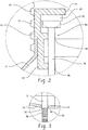
- FIGURE 2 is a partial enlarged view of FIGURE 1 .
- FIGURE 3 is a partial enlarged view of FIGURE 1 .
- FIGURE 4 is a perspective view of an LED integrated fluorescent lamp assembly with selected portions cut away for ease of illustration.
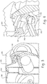
- FIGURE 5 is an enlarged view of the LED located in a base portion of the fluorescent lamp.
- FIGURE 6 is a further enlarged view of the LED located in the base portion.
- FIGURE 7 is an elevational view of another embodiment of an LED integrated fluorescent lamp assembly with selected portions cut away.
- FIGURE 8 is a schematic view of an LED integrated fluorescent lamp assembly according to another aspect of the present disclosure.
- FIGURE 9 is a partial enlarged view of FIGURE 8 .
- FIGURES 1-3 illustrate an LED integrated compact fluorescent lamp (“CFL") assembly 10 according to one aspect of the present disclosure.
- the assembly generally comprises a low-pressure fluorescent discharge lamp arrangement 12 including at least one low-pressure discharge tube 14 attached to a housing or shell 16, typically formed from plastic.
- the CFL assembly includes two generally U-shaped low-pressure discharge tubes 14, each discharge tube radiating white light (3000K-4000K, 480-1200lm).
- white light 3000K-4000K, 480-1200lm
- other fluorescent lamp arrangements could be used such as a helical discharge tube having an elongated path and in a manner that is generally well known in the art as will be evident in other embodiments described herein.
- the discharge tube arrangement 12 and shell 16 can be assembled together as a single element.
- the outer envelope is preferably made of a light-conducting material, such as glass or a light-transmissive plastic material.
- the outer envelope 20 envelops a physical volume 22, which can be, for example, evacuated or provided with a gas fill.
- the outer envelope is fixed to the shell 16 by a plastic collar 30 although alternate manners for attaching the outer envelope to the shell are contemplated.
- the collar is in turn attached to a first end section 32 of the shell 16 and extends outwardly from the shell to define an annular space 34 for receiving therein an open end portion 36 of the outer envelope.
- the outer envelope is fixedly secured to the plastic shell and collar.
- a second open end section 40 of the shell 16 is attached to a conductive metal base 42, which is shown in the form of a conventional Edison-type screw base.
- the base serves the purpose of mechanically holding, and acting as an electrical connection to, an associated lamp fitting or lamp holder (not shown).
- Lamp electronics such as an electronic ballast 50 are preferably located within the shell 16 of the embodiment of FIGURES 1-3 .
- the ballast 50 supplies the necessary power electronics, power supply, and circuit conditions (voltage, current and wave form) to drive or power the fluorescent discharge tubes 14.
- a heat reflector/insulator (not shown) may be positioned between the ballast 50 and the shell. The heat reflector shields the heat-sensitive electronic components of the ballast from the heat generated by the low pressure discharge lamp, and thereby extends the useful life of the lamp.
- At least one light-emitting diode (“LED”) light source 60 is mounted to the base 42 by a support 62 which is in contact with a wall of the base.
- the support 62 is preferably a heat conductive material such as metal in order to efficiently and effectively transfer heat away from the LED light source to the surrounding environment.
- the LED 60 is preferably a red light emitting LED (620-650nm, 25-60lm).
- An elongated light guide 70 is mounted in optical communication with a light emitting surface of the LED.
- the support 62 includes a first portion or arm 64 for housing the LED and a second portion or pair of spaced arms 66 for supporting the at least one light guide 70.
- the support is located in the base and engages an inner surface 72 of the base and the second end section 40 of the shell 16 to axially locate the support in the lamp assembly.
- the second portion 66 of the support extends axially outward from the threaded base and into the shell.
- the light guide 70 is supported at axially spaced locations to advantageously provide plural support points along one end of the light guide as it extends into the envelope.
- the red light radiated by the LED 60 is conducted toward the discharge tube arrangement in the outer bulb 20 by the elongated light guide 70.
- the light guide extends longitudinally from the LED into the volume 22 of the outer bulb 20, an axis of the light guide being generally parallel to an axis of the assembly 10.
- the light guide is generally cylindrical, although alternative shapes are contemplated.
- a light coupling material such as silicone gel, is located between the LED and light guide to effectively couple light emitted from the LED to the light guide for transmission into the volume 22.
- a first section 80 of the light guide which is disposed within the shell 16 and base 42, includes a cup-like member 82 dimensioned to at least partially surround the LED 60.
- the first section 80 is attached to the support 62 and extends through openings 84, 86 located on the first and second portions 64, 66, respectively.
- the first section 80 includes a coating to preclude transmission of the light through the sidewall of the light guide or is impermeable to prevent radiation of the red light from the LED through the sidewall of the light guide. This ensures that few irradiation losses occur in the first section 80 so as to provide maximum LED light to the second section 90.
- a second section 90 of the light guide extends through an opening 92 located on a wall 94 of the plastic shell 16.
- the second section 90 is light-permeable and at least partially includes a scattering pattern 96 for mixing the white light emitted by the discharge tubes 14 and the red light emitted by the LED.
- the outer bulb 20 is in the form of a diffuser which also has the function of mixing the light.
- This mixture of light radiated by the discharge tube arrangement 12 and the red light radiated by the LED 60 provides a substantially homogenous luminance distribution of the assembly 10. Light is desirably distributed along the longitudinal extent of the discharge tube arrangement thus leading to good color mixing along the longitudinal extent.
- the LED is preferably designed to be located at the coldest spot of the entire lamp assembly. Preferably, this location is also colder than the cold spot of the discharge tube. Again, currently available high efficiency red LEDs are temperature sensitive. Because the lumen output of the LED decreases significantly upon increasing ambient temperature, positioning the LED at the coldest spot of the lamp assembly contributes to the desired thermal management solution of the present disclosure.
- FIGURES 4-6 an LED integrated CFL assembly 200 according to another aspect of the present disclosure is shown in FIGURES 4-6 .
- the assembly 200 includes a helical low-pressure fluorescent lamp or discharge tube arrangement 202 attached to a shell or base 204.
- a glass envelope or outer bulb 206 encompasses the fluorescent lamp.
- the outer envelope is preferably a light-conducting material.
- the outer envelope is fixed to the shell 204 by plastic collar 210 that physically separates the fluorescent discharge tube from the lamp ballast assembly housed in the shell 204.
- An Edison-type threaded metal base 214 is attached to the shell for mechanically and electrically connecting at least the discharge tube arrangement to a lampholder (not shown).
- Lamp electronics such as electronic ballast 220 is preferably located within the shell 204 to control operation of the light sources, namely LED 230 and the compact fluorescent lamp.
- the LED 230 radiates red light and is operatively connected to a heat sink.
- strap 232 cooperates with the metal shell 214 to serve as the heat sink for the LED and advantageously conduct heat away from the LED to the outer shell, and so that the heat generated from the LED can be dissipated by conduction.
- Any suitable conductive material that conducts heat from the LED 230 can serve as a part of the heat sink.
- Light guide 240 in this assembly is used to convey the light output of the red light radiated by the LED to the CFL that emits white light.
- the light guide is supported at axially spaced locations 242, 244 by the ballast assembly 220 and the plastic collar 210.
- the light guide preferably contains the red light by internal reflection as the red light proceeds through a first or lower portion 242 from the LED located in the base and through the shell.
- the light guide extends a predetermined dimension above the collar 210 and adjacent the CFL where the red light exits a second or upper portion 244 of the light guide for mixing with the white light of the CFL.
- the LED receives power via first and second conductive leads or wires 250, 252 that extend from the ballast assembly 220 for connection with the LED located at terminal end of the first portion 242 of the light guide.
- the strap 232 can circumferentially surround at least a portion of the LED to provide effective heat transfer from the LED to the metal base.
- the strap provides a support site for the LED and the end of the light guide in addition to functioning as the means to thermally conduct heat from the LED to the base.
- FIGURE 7 is similar to that of FIGURES 4-6 (and thus like reference numerals identify like components) except where particularly noted otherwise.
- the heat sink includes an additional mass such as brass support ring 270.
- the brass support ring is preferably an annular member that can serve as a primary component of the heat sink assembly or as an intermediate component between the strap and metal shell. In either arrangement, heat is effectively conveyed from the LED.
- the light guide has a height that extends substantially the same height as the height of the CFL.
- the elongated light guide extends through the base from adjacent the LED where the light guide receives red light therefrom, passes through a first or upper end of the base, and extends along a major portion of the discharge lamp for intermixing the LED light with the CFL. It may also be desirable to fix a distal or terminal end 278 of the light guide remote from the LED relative to the CFL.
- a silicone rubber 280 fixes the distal end 278 of the light guide to the CFL 202. In this manner, the lamp is made more robust since it fixes the light guide against possible movement, has better heat conduction, and is more easily assembled.
- FIGURES 8 and 9 an LED integrated CFL assembly 300 according to yet another aspect of the present disclosure is shown in FIGURES 8 and 9 .
- the assembly 300 includes a low-pressure fluorescent lamp or discharge tube arrangement 302 attached to a shell 304.
- a light transmissive glass or plastic outer envelope 306 encompasses the fluorescent lamp.
- the outer envelope is fixed to the shell by a collar 310.
- a plug-in type base 314 is attached to the shell for mechanically and electrically connecting the assembly to a socket or lampholder 316.
- the lampholder is connected to power source (not shown).
- Lamp electronics such as an electronic ballast (not shown) need not be located within the shell in this embodiment but rather are incorporated into the lampholder.
- Contact pins 330 disposed on the base are in operative connection with the discharge tube arrangement.
- Bi-pin connections (not shown) are electrically associated with the ballast to cooperate with the contact pins and supply electric power to the fluorescent lamp 302 as is known in the art.
- the socket defines a cavity 340 dimensioned to receive the base 314 and contact pins 330.
- At least one red light emitting LED 350 is disposed in the socket 316.
- the red light radiated by the LED is conducted to a vicinity of the discharge tube arrangement 302 in the outer bulb 306 by a light guide assembly 352 ( FIGURE 8 ).
- the light guide assembly extends longitudinally through the socket base 314 to receive light from the LED, extends entirely through shell 304, and directs the red light into a volume 354 of the outer envelope.
- the light guide assembly may include a first part 360 disposed in the socket 316, and at least includes a portion 362 extending through the base 314 and shell 304, and a third part 364 extending into the outer envelope, for example, preferably along a substantial height of the CFL (and/or between the discharge tubes in this CFL arrangement).
- the first and second parts are connected via a coupling 370 located on an end of the second part, which is dimensioned to securely receive an end of the first part.
- a light coupling material such as silicone gel, is located between the first and second parts to enhance the light transmission therebetween.
- the first and second parts are configured or include a coating to limit transmission of red light radiating from the LED 350 through the sidewall of the first and second light guide portions. This ensures that minimum irradiation losses occur in the first and second parts so as to provide maximum LED light to the third part.
- the third part 364 is light-permeable and at least partially includes a scattering pattern 370 for mixing the white light emitted by the discharge tube arrangement and the red light emitted by the LED 350.
- FIGURES 1-3 one solution is to place the LED 60 at least partially in the base 42 and connect the LED thermally to the base. The light from the LED is conducted to the discharge tubes 4 by the light guide 70.
- FIGURES 4-7 include variations of this same general arrangement.
- yet another solution segregates the LED 350 from the CFL by locating the LED in the socket 316 of the lamp fixture.
- a light guide assembly 352 having an open end in the base 314 directs the red light radiating from the LED to the fluorescent lamp 302. This is generally a plug-in solution wherein the LED and the fluorescent lamp are driven by an external ballast.
- conventional CFLs with LED enhanced color quality have poor lumen maintenance and color stability.
- the present disclosure provides an innovative solution for producing vivid light and exhibit a very good red color rendering over the entire life span of the lamp.
- the present CFL assembly 10 is easy to differentiate from conventional CFLs. For example, a vivid, very apparent real color is achieved compared to the original CFL light source.
- the LED(s) need not necessarily be located in the socket or connected directly to the light guide as in the embodiment of FIGURES 8 and 9 , but could be placed outside the lamp, in the socket, in the housing of the supply electronics, coupled thermally with an external heat sink, or a group of LEDs located in a common heat sink with a common power supply and where the light is conducted to the socket, and ultimately adjacent the CFL or into the bulb by a light guide.
- a cladding or coating may not be necessary to limit the amount of light that escapes from the light guide since the air medium surrounding the light guide may be sufficient to minimize the amount of light that escapes.
Landscapes
- Engineering & Computer Science (AREA)
- Physics & Mathematics (AREA)
- Optics & Photonics (AREA)
- General Engineering & Computer Science (AREA)
- Microelectronics & Electronic Packaging (AREA)
- General Physics & Mathematics (AREA)
- Arrangement Of Elements, Cooling, Sealing, Or The Like Of Lighting Devices (AREA)
- Non-Portable Lighting Devices Or Systems Thereof (AREA)
Abstract
Description
- The present invention relates to a compact fluorescent lamp assembly, and more particularly, to an LED integrated compact fluorescent lamp assembly.
- Prior art solutions to low color rendering of compact fluorescent lamps (CFL) have concentrated on optical properties, phosphors, CRI, etc. Although full spectrum fluorescent lamps exist, these lamps have low lumens per watt (LPW), poor color and lumen maintenance, or low color rendering of the color red. Therefore, the red containing colors seem significantly different when illuminated by a conventional CFL compared to an incandescent lamp or natural sunlight. For example, certain colors lack the vivid, very apparent red color with conventional CFL light sources. There are high color rendering CFLs in the market that use phosphors to address the desired color rendering.
- Unfortunately, the phosphor solution for enhancing color quality is inadequate because the discharge deteriorates the phosphor and the lumen maintenance and color stability of these lamps do not meet customer requirements.
- Adding a small portion (approximately 5-10% of the white light produced by the CFL) of red light produced by a light-emitting diode ("LED") based light source to the white light provided by the CFL is another solution to enhance the red color rendering.
- On the other hand, adding the red color via an LED encounters issues because currently available high efficiency red LEDs are temperature sensitive. The lumen output of the LED decreases significantly upon increasing ambient temperature. For example, warming to 80C, the efficiency and lumen output of the LED decreases to approximately half of the values measured at 25C. Unfortunately, the working temperature of a low-pressure fluorescent discharge tube or CFL is approximately 80-110C, and the surrounding components (e.g., outer bulb and ballast) are heated to approximately 60-70C by heat conduction and convection. Thus, the LED has to be thermally insulated from the CFL, and the heat produced by the LED (approximately 1-3W) has to be dissipated in order maximize the efficiency and lumen output of the LED.
- As a result, a need exists for a lamp assembly that provides light mixing and thermal management solutions of an LED light source that is combined with a CFL light source in order to improve light quality and color rendering with a desired useful life.
US 2005/0195600 A1 shows a lighting assembly according to the preamble of claim 1. - Various aspects and embodiments of the present invention are defined by the appended claims.
-
FIGURE 1 is a schematic view of an LED integrated fluorescent lamp assembly according to one aspect of the present disclosure. -
FIGURE 2 is a partial enlarged view ofFIGURE 1 . -
FIGURE 3 is a partial enlarged view ofFIGURE 1 . -
FIGURE 4 is a perspective view of an LED integrated fluorescent lamp assembly with selected portions cut away for ease of illustration. -
FIGURE 5 is an enlarged view of the LED located in a base portion of the fluorescent lamp. -
FIGURE 6 is a further enlarged view of the LED located in the base portion. -
FIGURE 7 is an elevational view of another embodiment of an LED integrated fluorescent lamp assembly with selected portions cut away. -
FIGURE 8 is a schematic view of an LED integrated fluorescent lamp assembly according to another aspect of the present disclosure. -
FIGURE 9 is a partial enlarged view ofFIGURE 8 . - Referring now to the drawings, wherein like numerals refer to like parts throughout the several views,
FIGURES 1-3 illustrate an LED integrated compact fluorescent lamp ("CFL")assembly 10 according to one aspect of the present disclosure. The assembly generally comprises a low-pressure fluorescentdischarge lamp arrangement 12 including at least one low-pressure discharge tube 14 attached to a housing orshell 16, typically formed from plastic. In the depicted embodiment, the CFL assembly includes two generally U-shaped low-pressure discharge tubes 14, each discharge tube radiating white light (3000K-4000K, 480-1200lm). Of course, it will be appreciated that other fluorescent lamp arrangements could be used such as a helical discharge tube having an elongated path and in a manner that is generally well known in the art as will be evident in other embodiments described herein. Thedischarge tube arrangement 12 andshell 16 can be assembled together as a single element. - An envelope such as glass envelope or
outer bulb 20 encompasses the fluorescentdischarge lamp arrangement 12 in this illustrated embodiment, however, it will be appreciated that the outer envelope is not present in all intended end uses of this disclosure. The outer envelope is preferably made of a light-conducting material, such as glass or a light-transmissive plastic material. Theouter envelope 20 envelops aphysical volume 22, which can be, for example, evacuated or provided with a gas fill. As shown, the outer envelope is fixed to theshell 16 by aplastic collar 30 although alternate manners for attaching the outer envelope to the shell are contemplated. The collar is in turn attached to afirst end section 32 of theshell 16 and extends outwardly from the shell to define anannular space 34 for receiving therein anopen end portion 36 of the outer envelope. The outer envelope is fixedly secured to the plastic shell and collar. A secondopen end section 40 of theshell 16 is attached to aconductive metal base 42, which is shown in the form of a conventional Edison-type screw base. The base serves the purpose of mechanically holding, and acting as an electrical connection to, an associated lamp fitting or lamp holder (not shown). - Lamp electronics such as an
electronic ballast 50 are preferably located within theshell 16 of the embodiment ofFIGURES 1-3 . As is well known, theballast 50 supplies the necessary power electronics, power supply, and circuit conditions (voltage, current and wave form) to drive or power thefluorescent discharge tubes 14. Further, a heat reflector/insulator (not shown) may be positioned between theballast 50 and the shell. The heat reflector shields the heat-sensitive electronic components of the ballast from the heat generated by the low pressure discharge lamp, and thereby extends the useful life of the lamp. - With additional reference to
FIGURE 2 , at least one light-emitting diode ("LED")light source 60 is mounted to thebase 42 by asupport 62 which is in contact with a wall of the base. In this particular instance, thesupport 62 is preferably a heat conductive material such as metal in order to efficiently and effectively transfer heat away from the LED light source to the surrounding environment. TheLED 60 is preferably a red light emitting LED (620-650nm, 25-60lm). Anelongated light guide 70 is mounted in optical communication with a light emitting surface of the LED. In the depicted embodiment, thesupport 62 includes a first portion orarm 64 for housing the LED and a second portion or pair of spaced arms 66 for supporting the at least onelight guide 70. The support is located in the base and engages aninner surface 72 of the base and thesecond end section 40 of theshell 16 to axially locate the support in the lamp assembly. The second portion 66 of the support extends axially outward from the threaded base and into the shell. In this manner, thelight guide 70 is supported at axially spaced locations to advantageously provide plural support points along one end of the light guide as it extends into the envelope. - As indicated previously, high efficiency LEDs which radiate red light are temperature sensitive. Thus, controlling the temperature of the LED is an important aspect of optimum performance of LED systems. In general, the cooler the environment, the higher the light output from an LED. Higher temperatures generally reduce light output. In warmer environments and at higher currents, the temperature of an LED semi-conducting element increases. The light output of an LED for a constant current varies as a function of its junction temperature. Higher ambient temperature leads to higher junction temperatures, which can increase the degradation rate of an LED junction element, possibly causing the light output of an LED to irreversibly decrease over the long term at a faster rate than at lower temperatures. Locating an LED in an insulated and relatively small space, such as the
base 42, will likely result in rapidly increased junction temperature and suboptimal performance. However, by mounting theLED 60 on thesupport 62 which is in physical contact with thebase 42, heat can be advantageously removed from the LED by thermal conduction. - With reference to
FIGURE 3 , the red light radiated by theLED 60 is conducted toward the discharge tube arrangement in theouter bulb 20 by theelongated light guide 70. The light guide extends longitudinally from the LED into thevolume 22 of theouter bulb 20, an axis of the light guide being generally parallel to an axis of theassembly 10. In the depicted embodiment, the light guide is generally cylindrical, although alternative shapes are contemplated. A light coupling material, such as silicone gel, is located between the LED and light guide to effectively couple light emitted from the LED to the light guide for transmission into thevolume 22. Afirst section 80 of the light guide, which is disposed within theshell 16 andbase 42, includes a cup-like member 82 dimensioned to at least partially surround theLED 60. Thefirst section 80 is attached to thesupport 62 and extends throughopenings second portions 64, 66, respectively. Thefirst section 80 includes a coating to preclude transmission of the light through the sidewall of the light guide or is impermeable to prevent radiation of the red light from the LED through the sidewall of the light guide. This ensures that few irradiation losses occur in thefirst section 80 so as to provide maximum LED light to thesecond section 90. - A
second section 90 of the light guide extends through anopening 92 located on awall 94 of theplastic shell 16. Thesecond section 90 is light-permeable and at least partially includes a scattering pattern 96 for mixing the white light emitted by thedischarge tubes 14 and the red light emitted by the LED. It should be appreciated that theouter bulb 20 is in the form of a diffuser which also has the function of mixing the light. This mixture of light radiated by thedischarge tube arrangement 12 and the red light radiated by theLED 60 provides a substantially homogenous luminance distribution of theassembly 10. Light is desirably distributed along the longitudinal extent of the discharge tube arrangement thus leading to good color mixing along the longitudinal extent. - The LED is preferably designed to be located at the coldest spot of the entire lamp assembly. Preferably, this location is also colder than the cold spot of the discharge tube. Again, currently available high efficiency red LEDs are temperature sensitive. Because the lumen output of the LED decreases significantly upon increasing ambient temperature, positioning the LED at the coldest spot of the lamp assembly contributes to the desired thermal management solution of the present disclosure.
- Similar to the aforementioned embodiment, an LED integrated
CFL assembly 200 according to another aspect of the present disclosure is shown inFIGURES 4-6 . Theassembly 200 includes a helical low-pressure fluorescent lamp ordischarge tube arrangement 202 attached to a shell orbase 204. A glass envelope orouter bulb 206 encompasses the fluorescent lamp. Like the embodiment ofFIGURE 1 , the outer envelope is preferably a light-conducting material. The outer envelope is fixed to theshell 204 byplastic collar 210 that physically separates the fluorescent discharge tube from the lamp ballast assembly housed in theshell 204. An Edison-type threadedmetal base 214 is attached to the shell for mechanically and electrically connecting at least the discharge tube arrangement to a lampholder (not shown). Lamp electronics such aselectronic ballast 220 is preferably located within theshell 204 to control operation of the light sources, namely LED 230 and the compact fluorescent lamp. - The
LED 230 radiates red light and is operatively connected to a heat sink. In this embodiment,strap 232 cooperates with themetal shell 214 to serve as the heat sink for the LED and advantageously conduct heat away from the LED to the outer shell, and so that the heat generated from the LED can be dissipated by conduction. Any suitable conductive material that conducts heat from theLED 230 can serve as a part of the heat sink. By locating the heat sink in the lower inside portion of the base the LED is protected from the operating temperature of the compact fluorescent lamp. Theplastic collar 204 and the ballast assembly are interposed between the CFL and the LED to further isolate the LED from the elevated temperatures. -
Light guide 240 in this assembly is used to convey the light output of the red light radiated by the LED to the CFL that emits white light. Here, the light guide is supported at axially spacedlocations ballast assembly 220 and theplastic collar 210. The light guide preferably contains the red light by internal reflection as the red light proceeds through a first orlower portion 242 from the LED located in the base and through the shell. The light guide extends a predetermined dimension above thecollar 210 and adjacent the CFL where the red light exits a second orupper portion 244 of the light guide for mixing with the white light of the CFL. - As seen in
FIGURES 5 and 6 , the LED receives power via first and second conductive leads orwires ballast assembly 220 for connection with the LED located at terminal end of thefirst portion 242 of the light guide. Thestrap 232 can circumferentially surround at least a portion of the LED to provide effective heat transfer from the LED to the metal base. Thus, the strap provides a support site for the LED and the end of the light guide in addition to functioning as the means to thermally conduct heat from the LED to the base. - The embodiment of
FIGURE 7 is similar to that ofFIGURES 4-6 (and thus like reference numerals identify like components) except where particularly noted otherwise. For example, although the LED is again located in the base, the heat sink includes an additional mass such asbrass support ring 270. The brass support ring is preferably an annular member that can serve as a primary component of the heat sink assembly or as an intermediate component between the strap and metal shell. In either arrangement, heat is effectively conveyed from the LED. In addition, the light guide has a height that extends substantially the same height as the height of the CFL. Thus, it will also be appreciated that the elongated light guide extends through the base from adjacent the LED where the light guide receives red light therefrom, passes through a first or upper end of the base, and extends along a major portion of the discharge lamp for intermixing the LED light with the CFL. It may also be desirable to fix a distal orterminal end 278 of the light guide remote from the LED relative to the CFL. In this embodiment, asilicone rubber 280 fixes thedistal end 278 of the light guide to theCFL 202. In this manner, the lamp is made more robust since it fixes the light guide against possible movement, has better heat conduction, and is more easily assembled. - Similar to the aforementioned embodiments, an LED integrated CFL assembly 300 according to yet another aspect of the present disclosure is shown in
FIGURES 8 and 9 . The assembly 300 includes a low-pressure fluorescent lamp ordischarge tube arrangement 302 attached to ashell 304. A light transmissive glass or plasticouter envelope 306 encompasses the fluorescent lamp. The outer envelope is fixed to the shell by acollar 310. A plug-intype base 314 is attached to the shell for mechanically and electrically connecting the assembly to a socket orlampholder 316. The lampholder, in turn, is connected to power source (not shown). Lamp electronics such as an electronic ballast (not shown) need not be located within the shell in this embodiment but rather are incorporated into the lampholder. Contact pins 330 disposed on the base are in operative connection with the discharge tube arrangement. Bi-pin connections (not shown) are electrically associated with the ballast to cooperate with the contact pins and supply electric power to thefluorescent lamp 302 as is known in the art. The socket defines acavity 340 dimensioned to receive thebase 314 and contact pins 330. - At least one red
light emitting LED 350 is disposed in thesocket 316. The red light radiated by the LED is conducted to a vicinity of thedischarge tube arrangement 302 in theouter bulb 306 by a light guide assembly 352 (FIGURE 8 ). The light guide assembly extends longitudinally through thesocket base 314 to receive light from the LED, extends entirely throughshell 304, and directs the red light into avolume 354 of the outer envelope. The light guide assembly may include a first part 360 disposed in thesocket 316, and at least includes aportion 362 extending through thebase 314 andshell 304, and athird part 364 extending into the outer envelope, for example, preferably along a substantial height of the CFL (and/or between the discharge tubes in this CFL arrangement). The first and second parts are connected via acoupling 370 located on an end of the second part, which is dimensioned to securely receive an end of the first part. A light coupling material, such as silicone gel, is located between the first and second parts to enhance the light transmission therebetween. The first and second parts are configured or include a coating to limit transmission of red light radiating from theLED 350 through the sidewall of the first and second light guide portions. This ensures that minimum irradiation losses occur in the first and second parts so as to provide maximum LED light to the third part. Thethird part 364, on the other hand, is light-permeable and at least partially includes ascattering pattern 370 for mixing the white light emitted by the discharge tube arrangement and the red light emitted by theLED 350. - The present disclosure provides various solutions to adjust the thermal requirements of the LED. As shown in
FIGURES 1-3 , one solution is to place theLED 60 at least partially in thebase 42 and connect the LED thermally to the base. The light from the LED is conducted to the discharge tubes 4 by thelight guide 70.FIGURES 4-7 include variations of this same general arrangement. As shown inFIGURES 8 and 9 , yet another solution segregates theLED 350 from the CFL by locating the LED in thesocket 316 of the lamp fixture. Alight guide assembly 352 having an open end in thebase 314 directs the red light radiating from the LED to thefluorescent lamp 302. This is generally a plug-in solution wherein the LED and the fluorescent lamp are driven by an external ballast. - As indicated previously, conventional CFLs with LED enhanced color quality have poor lumen maintenance and color stability. The present disclosure provides an innovative solution for producing vivid light and exhibit a very good red color rendering over the entire life span of the lamp. Thus, when energized, the
present CFL assembly 10 is easy to differentiate from conventional CFLs. For example, a vivid, very apparent real color is achieved compared to the original CFL light source. - It will be appreciated that various of the above-disclosed and other features and functions, or alternatives thereof, may be desirably combined into many other different systems or applications. Also that various presently unforeseen or unanticipated alternatives, modifications, variations or improvements therein may be subsequently made by those skilled in the art which are also intended to be encompassed by the following claims. For example, although the description refers to one LED, it will be recognized that at least one LED (i.e., plural LEDs) may be incorporated into a modified arrangement at a location adjacent the second end of the light guide in order to thermally isolate the LEDs from the discharge lamp. The LED(s) need not necessarily be located in the socket or connected directly to the light guide as in the embodiment of
FIGURES 8 and 9 , but could be placed outside the lamp, in the socket, in the housing of the supply electronics, coupled thermally with an external heat sink, or a group of LEDs located in a common heat sink with a common power supply and where the light is conducted to the socket, and ultimately adjacent the CFL or into the bulb by a light guide. Moreover, a cladding or coating may not be necessary to limit the amount of light that escapes from the light guide since the air medium surrounding the light guide may be sufficient to minimize the amount of light that escapes.
Claims (5)
- A lighting assembly (10) comprising:a low pressure discharge lamp for radiating light (12);at least one light-emitting diode (LED) (60) emitting light;a light guide (70) receiving light from the LED and intermixing the LED light with the discharge lamp light;an operating circuit (50) for supplying power to at least the discharge lamp;a metal base (42) for mechanically and electrically connecting at least the discharge lamp to an associated lampholder; andthe at least one LED in thermal conductive relation with the base,characterised in that
said lighting assembly (10) further comprising a heat sink (62) interposed between the light emitting diode (60) and the base (42). - The lighting assembly (10) of claim 1 wherein the LED (60) abuttingly contacts the heat sink (62), and the heat sink abuttingly contacts the base (42).
- The lighting assembly (10) of claim 1 wherein the heat sink (62) is a metal component.
- The lighting assembly (10) of claim 1 wherein the heat sink (62) supports the light guide (70).
- The lighting assembly (10) of claim 4 wherein the heat sink (62) supports the light guide (70) at first and second spaced locations.
Priority Applications (1)
| Application Number | Priority Date | Filing Date | Title |
|---|---|---|---|
| PL08871677T PL2238810T3 (en) | 2008-01-29 | 2008-12-18 | THERMAL MANAGEMENT OF LED DIODES INTEGRATED WITH COMPACT FLUORESCENT LAMPS |
Applications Claiming Priority (2)
| Application Number | Priority Date | Filing Date | Title |
|---|---|---|---|
| US12/021,880 US7543957B1 (en) | 2008-01-29 | 2008-01-29 | Thermal management of LEDS integrated to compact fluorescent lamps |
| PCT/US2008/087443 WO2009097063A2 (en) | 2008-01-29 | 2008-12-18 | Thermal management of leds integrated to compact fluorescent lamps |
Publications (2)
| Publication Number | Publication Date |
|---|---|
| EP2238810A2 EP2238810A2 (en) | 2010-10-13 |
| EP2238810B1 true EP2238810B1 (en) | 2012-05-16 |
Family
ID=40688630
Family Applications (1)
| Application Number | Title | Priority Date | Filing Date |
|---|---|---|---|
| EP08871677A Not-in-force EP2238810B1 (en) | 2008-01-29 | 2008-12-18 | Thermal management of leds integrated to compact fluorescent lamps |
Country Status (7)
| Country | Link |
|---|---|
| US (1) | US7543957B1 (en) |
| EP (1) | EP2238810B1 (en) |
| JP (1) | JP5276675B2 (en) |
| KR (1) | KR20100102689A (en) |
| CN (1) | CN101933398B (en) |
| PL (1) | PL2238810T3 (en) |
| WO (1) | WO2009097063A2 (en) |
Families Citing this family (18)
| Publication number | Priority date | Publication date | Assignee | Title |
|---|---|---|---|---|
| US8066417B2 (en) * | 2009-08-28 | 2011-11-29 | General Electric Company | Light emitting diode-light guide coupling apparatus |
| KR200452816Y1 (en) * | 2009-09-14 | 2011-03-21 | (주) 코콤 | LED lamp with insulation wall for ballast circuit board protection |
| JP4907726B2 (en) * | 2010-04-19 | 2012-04-04 | シャープ株式会社 | Heat dissipation device and lighting device |
| JP4945657B2 (en) * | 2010-04-19 | 2012-06-06 | 日立アプライアンス株式会社 | LED bulb |
| PH12013500176A1 (en) | 2010-07-27 | 2013-03-18 | Scentsy Inc | Scent warmers having non-incandescent heating and light-emitting devices and related methods |
| EP3653924B1 (en) * | 2010-12-22 | 2024-04-17 | Signify Holding B.V. | Lighting device |
| CN102537871B (en) * | 2010-12-31 | 2015-08-05 | 通用电气公司 | Hybrid compact fluorescent lamp fixing method |
| US8772675B2 (en) | 2011-06-15 | 2014-07-08 | Scentsy, Inc. | Electrical lighting and heating modules, assemblies and scent warmers comprising such modules, and related methods |
| US8878102B2 (en) | 2011-06-15 | 2014-11-04 | Scentsy, Inc. | Base structures, scent warmers including such base structures, and related methods |
| CN103703307B (en) | 2011-10-31 | 2015-08-05 | 皇家飞利浦有限公司 | There is the compact light output arrangement of wavelength convert |
| TWM439153U (en) * | 2011-12-29 | 2012-10-11 | Xu Xiu Yu | Lamp structure with switchable illumination modes |
| KR101365632B1 (en) * | 2012-02-10 | 2014-02-24 | 강성석 | Compact discharge lamp |
| KR101365633B1 (en) * | 2012-02-10 | 2014-02-24 | 강성석 | Discharge lamp |
| EP2936670B1 (en) | 2012-12-21 | 2020-03-25 | ABB Power Grids Switzerland AG | Overmodulation type pulse dropping in pwm for converter cells in a modular multilevel ac/dc converter |
| US9354386B2 (en) * | 2013-10-25 | 2016-05-31 | 3M Innovative Properties Company | Solid state area light and spotlight with light guide and integrated thermal guide |
| CN105987306A (en) * | 2015-02-16 | 2016-10-05 | 上海宏源照明电器有限公司 | Mixed light source combined with semiconductor luminous wafer and gas discharge lamp |
| JP6732203B2 (en) | 2017-02-22 | 2020-07-29 | Smc株式会社 | Waterproof manifold solenoid valve |
| WO2022008339A1 (en) * | 2020-07-07 | 2022-01-13 | Signify Holding B.V. | A light guide coupled luminaire |
Family Cites Families (25)
| Publication number | Priority date | Publication date | Assignee | Title |
|---|---|---|---|---|
| JPH10275600A (en) | 1997-03-28 | 1998-10-13 | Matsushita Electric Ind Co Ltd | Discharge lamps and discharge lamp fixtures |
| DE19829270B4 (en) | 1997-07-02 | 2006-03-16 | Patent-Treuhand-Gesellschaft für elektrische Glühlampen mbH | lamp |
| US6666567B1 (en) | 1999-12-28 | 2003-12-23 | Honeywell International Inc. | Methods and apparatus for a light source with a raised LED structure |
| DE20007134U1 (en) | 2000-04-18 | 2000-08-17 | OSRAM Opto Semiconductors GmbH & Co. oHG, 93049 Regensburg | Luminaire with adjustable color location |
| US6400104B1 (en) | 2000-09-12 | 2002-06-04 | Byung Il Ham | Fluorescent lamp assembly with nightlight |
| CN1457622A (en) | 2001-02-02 | 2003-11-19 | 皇家菲利浦电子有限公司 | Integrated light source |
| CN1640199B (en) * | 2002-01-07 | 2010-09-08 | 奥斯兰姆有限公司 | lamp |
| EP1466505B1 (en) | 2002-01-10 | 2012-08-01 | Osram Ag | Lamp |
| JP2004010344A (en) | 2002-06-12 | 2004-01-15 | Kawasaki Heavy Ind Ltd | Wire material take-up device |
| DE10233768A1 (en) | 2002-07-25 | 2004-02-12 | Philips Intellectual Property & Standards Gmbh | Lamp system with green-blue gas discharge lamp and yellow-red LED |
| CN1706023A (en) | 2002-10-14 | 2005-12-07 | 皇家飞利浦电子股份有限公司 | Luminous body for generating white light |
| JP2004165105A (en) | 2002-11-08 | 2004-06-10 | Hitachi Lighting Ltd | Fluorescent lighting equipment |
| JP4049260B2 (en) * | 2003-03-11 | 2008-02-20 | 株式会社小糸製作所 | Vehicle lighting |
| ES2291909T3 (en) * | 2003-07-02 | 2008-03-01 | S.C. JOHNSON & SON, INC. | LAMP AND BULB FOR LIGHTING AND ENVIRONMENTAL LIGHT. |
| US7604378B2 (en) * | 2003-07-02 | 2009-10-20 | S.C. Johnson & Son, Inc. | Color changing outdoor lights with active ingredient and sound emission |
| WO2005024478A1 (en) | 2003-09-11 | 2005-03-17 | Philips Intellectual Property & Standards Gmbh | Lamp system |
| AU2005219978B2 (en) * | 2004-03-03 | 2010-08-26 | S.C. Johnson & Son, Inc. | LED light bulb with active ingredient emission |
| DE102004020122B4 (en) * | 2004-04-24 | 2007-06-06 | Diehl Aerospace Gmbh | LED tubes hybrid lighting device |
| DE102004045515A1 (en) | 2004-09-20 | 2006-03-30 | Patent-Treuhand-Gesellschaft für elektrische Glühlampen mbH | Illumination system with at least two light sources and method for operating such a lighting system |
| DE102005032314A1 (en) | 2005-07-11 | 2007-01-18 | Patent-Treuhand-Gesellschaft für elektrische Glühlampen mbH | lamp arrangement |
| DE102005032315A1 (en) | 2005-07-11 | 2007-01-18 | Patent-Treuhand-Gesellschaft für elektrische Glühlampen mbH | lamp |
| JP2007227342A (en) * | 2005-08-31 | 2007-09-06 | Toshiba Lighting & Technology Corp | Light bulb type fluorescent lamp device |
| KR101243402B1 (en) * | 2005-12-27 | 2013-03-13 | 엘지디스플레이 주식회사 | Apparatus for driving hybrid backlight of LCD |
| JP4535009B2 (en) * | 2006-03-15 | 2010-09-01 | 東芝ライテック株式会社 | Light bulb type fluorescent lamp device |
| CN101461286A (en) | 2006-04-05 | 2009-06-17 | 皇家飞利浦电子股份有限公司 | Lamp system comprising a primary light source and a secondary light source |
-
2008
- 2008-01-29 US US12/021,880 patent/US7543957B1/en not_active Expired - Fee Related
- 2008-12-18 JP JP2010544979A patent/JP5276675B2/en not_active Expired - Fee Related
- 2008-12-18 CN CN2008801262269A patent/CN101933398B/en not_active Expired - Fee Related
- 2008-12-18 PL PL08871677T patent/PL2238810T3/en unknown
- 2008-12-18 KR KR1020107017029A patent/KR20100102689A/en not_active Ceased
- 2008-12-18 EP EP08871677A patent/EP2238810B1/en not_active Not-in-force
- 2008-12-18 WO PCT/US2008/087443 patent/WO2009097063A2/en not_active Ceased
Also Published As
| Publication number | Publication date |
|---|---|
| WO2009097063A2 (en) | 2009-08-06 |
| CN101933398B (en) | 2012-12-12 |
| CN101933398A (en) | 2010-12-29 |
| JP2011511413A (en) | 2011-04-07 |
| JP5276675B2 (en) | 2013-08-28 |
| WO2009097063A3 (en) | 2010-05-27 |
| EP2238810A2 (en) | 2010-10-13 |
| PL2238810T3 (en) | 2012-10-31 |
| US7543957B1 (en) | 2009-06-09 |
| KR20100102689A (en) | 2010-09-24 |
Similar Documents
| Publication | Publication Date | Title |
|---|---|---|
| US7543957B1 (en) | Thermal management of LEDS integrated to compact fluorescent lamps | |
| KR102025016B1 (en) | Light emitting diode-light guide coupling apparatus | |
| US7461964B1 (en) | Fluorescent lighting fixture assemblies | |
| US8853921B2 (en) | Heat removal design for LED bulbs | |
| US8985815B2 (en) | Light bulb with upward and downward facing LEDs having heat dissipation | |
| US9863628B2 (en) | Semiconductor retrofit lamp having connecting elements arranged on two sides | |
| KR101075339B1 (en) | Re-entrant cavity fluorescent lamp system | |
| US20100026157A1 (en) | Lamp and lighting equipment | |
| US20150308630A1 (en) | Led lamp | |
| US20070076426A1 (en) | Lamp with two light sources | |
| US6024465A (en) | Lighting fixture | |
| US7390106B2 (en) | Lighting apparatus | |
| CN209991278U (en) | LED (light-emitting diode) barrel spotlight | |
| US7748871B2 (en) | Lighting apparatus | |
| US20180299080A1 (en) | Led lamp with coated substrate | |
| WO2008084416A1 (en) | Illuminating device | |
| JP5551562B2 (en) | lamp | |
| US20110304255A1 (en) | Extended-life Lamp With Integral Cooling | |
| KR101160842B1 (en) | High Power LED Package Module | |
| CN101382272A (en) | LED bar lamp with heat radiation function | |
| CN101794693A (en) | Adapter for at least one compact fluorescent lamp |
Legal Events
| Date | Code | Title | Description |
|---|---|---|---|
| PUAI | Public reference made under article 153(3) epc to a published international application that has entered the european phase |
Free format text: ORIGINAL CODE: 0009012 |
|
| AK | Designated contracting states |
Kind code of ref document: A2 Designated state(s): AT BE BG CH CY CZ DE DK EE ES FI FR GB GR HR HU IE IS IT LI LT LU LV MC MT NL NO PL PT RO SE SI SK TR |
|
| AX | Request for extension of the european patent |
Extension state: AL BA MK RS |
|
| 17P | Request for examination filed |
Effective date: 20101129 |
|
| RBV | Designated contracting states (corrected) |
Designated state(s): AT BE BG CH CY CZ DE DK EE ES FI FR GB GR HR HU IE IS IT LI LT LU LV MC MT NL NO PL PT RO SE SI SK TR |
|
| DAX | Request for extension of the european patent (deleted) | ||
| 17Q | First examination report despatched |
Effective date: 20110411 |
|
| GRAP | Despatch of communication of intention to grant a patent |
Free format text: ORIGINAL CODE: EPIDOSNIGR1 |
|
| GRAS | Grant fee paid |
Free format text: ORIGINAL CODE: EPIDOSNIGR3 |
|
| GRAA | (expected) grant |
Free format text: ORIGINAL CODE: 0009210 |
|
| AK | Designated contracting states |
Kind code of ref document: B1 Designated state(s): AT BE BG CH CY CZ DE DK EE ES FI FR GB GR HR HU IE IS IT LI LT LU LV MC MT NL NO PL PT RO SE SI SK TR |
|
| REG | Reference to a national code |
Ref country code: GB Ref legal event code: FG4D |
|
| REG | Reference to a national code |
Ref country code: CH Ref legal event code: EP |
|
| REG | Reference to a national code |
Ref country code: AT Ref legal event code: REF Ref document number: 558591 Country of ref document: AT Kind code of ref document: T Effective date: 20120615 |
|
| REG | Reference to a national code |
Ref country code: IE Ref legal event code: FG4D |
|
| REG | Reference to a national code |
Ref country code: DE Ref legal event code: R096 Ref document number: 602008015766 Country of ref document: DE Effective date: 20120712 |
|
| REG | Reference to a national code |
Ref country code: NL Ref legal event code: T3 |
|
| REG | Reference to a national code |
Ref country code: LT Ref legal event code: MG4D Effective date: 20120516 |
|
| PG25 | Lapsed in a contracting state [announced via postgrant information from national office to epo] |
Ref country code: SE Free format text: LAPSE BECAUSE OF FAILURE TO SUBMIT A TRANSLATION OF THE DESCRIPTION OR TO PAY THE FEE WITHIN THE PRESCRIBED TIME-LIMIT Effective date: 20120516 Ref country code: NO Free format text: LAPSE BECAUSE OF FAILURE TO SUBMIT A TRANSLATION OF THE DESCRIPTION OR TO PAY THE FEE WITHIN THE PRESCRIBED TIME-LIMIT Effective date: 20120816 Ref country code: IS Free format text: LAPSE BECAUSE OF FAILURE TO SUBMIT A TRANSLATION OF THE DESCRIPTION OR TO PAY THE FEE WITHIN THE PRESCRIBED TIME-LIMIT Effective date: 20120916 Ref country code: FI Free format text: LAPSE BECAUSE OF FAILURE TO SUBMIT A TRANSLATION OF THE DESCRIPTION OR TO PAY THE FEE WITHIN THE PRESCRIBED TIME-LIMIT Effective date: 20120516 Ref country code: CY Free format text: LAPSE BECAUSE OF FAILURE TO SUBMIT A TRANSLATION OF THE DESCRIPTION OR TO PAY THE FEE WITHIN THE PRESCRIBED TIME-LIMIT Effective date: 20120516 Ref country code: LT Free format text: LAPSE BECAUSE OF FAILURE TO SUBMIT A TRANSLATION OF THE DESCRIPTION OR TO PAY THE FEE WITHIN THE PRESCRIBED TIME-LIMIT Effective date: 20120516 |
|
| REG | Reference to a national code |
Ref country code: PL Ref legal event code: T3 |
|
| REG | Reference to a national code |
Ref country code: AT Ref legal event code: MK05 Ref document number: 558591 Country of ref document: AT Kind code of ref document: T Effective date: 20120516 |
|
| PG25 | Lapsed in a contracting state [announced via postgrant information from national office to epo] |
Ref country code: SI Free format text: LAPSE BECAUSE OF FAILURE TO SUBMIT A TRANSLATION OF THE DESCRIPTION OR TO PAY THE FEE WITHIN THE PRESCRIBED TIME-LIMIT Effective date: 20120516 Ref country code: GR Free format text: LAPSE BECAUSE OF FAILURE TO SUBMIT A TRANSLATION OF THE DESCRIPTION OR TO PAY THE FEE WITHIN THE PRESCRIBED TIME-LIMIT Effective date: 20120817 Ref country code: HR Free format text: LAPSE BECAUSE OF FAILURE TO SUBMIT A TRANSLATION OF THE DESCRIPTION OR TO PAY THE FEE WITHIN THE PRESCRIBED TIME-LIMIT Effective date: 20120516 Ref country code: LV Free format text: LAPSE BECAUSE OF FAILURE TO SUBMIT A TRANSLATION OF THE DESCRIPTION OR TO PAY THE FEE WITHIN THE PRESCRIBED TIME-LIMIT Effective date: 20120516 Ref country code: PT Free format text: LAPSE BECAUSE OF FAILURE TO SUBMIT A TRANSLATION OF THE DESCRIPTION OR TO PAY THE FEE WITHIN THE PRESCRIBED TIME-LIMIT Effective date: 20120917 |
|
| PG25 | Lapsed in a contracting state [announced via postgrant information from national office to epo] |
Ref country code: BE Free format text: LAPSE BECAUSE OF FAILURE TO SUBMIT A TRANSLATION OF THE DESCRIPTION OR TO PAY THE FEE WITHIN THE PRESCRIBED TIME-LIMIT Effective date: 20120516 |
|
| PG25 | Lapsed in a contracting state [announced via postgrant information from national office to epo] |
Ref country code: AT Free format text: LAPSE BECAUSE OF FAILURE TO SUBMIT A TRANSLATION OF THE DESCRIPTION OR TO PAY THE FEE WITHIN THE PRESCRIBED TIME-LIMIT Effective date: 20120516 Ref country code: RO Free format text: LAPSE BECAUSE OF FAILURE TO SUBMIT A TRANSLATION OF THE DESCRIPTION OR TO PAY THE FEE WITHIN THE PRESCRIBED TIME-LIMIT Effective date: 20120516 Ref country code: EE Free format text: LAPSE BECAUSE OF FAILURE TO SUBMIT A TRANSLATION OF THE DESCRIPTION OR TO PAY THE FEE WITHIN THE PRESCRIBED TIME-LIMIT Effective date: 20120516 Ref country code: DK Free format text: LAPSE BECAUSE OF FAILURE TO SUBMIT A TRANSLATION OF THE DESCRIPTION OR TO PAY THE FEE WITHIN THE PRESCRIBED TIME-LIMIT Effective date: 20120516 Ref country code: SK Free format text: LAPSE BECAUSE OF FAILURE TO SUBMIT A TRANSLATION OF THE DESCRIPTION OR TO PAY THE FEE WITHIN THE PRESCRIBED TIME-LIMIT Effective date: 20120516 Ref country code: CZ Free format text: LAPSE BECAUSE OF FAILURE TO SUBMIT A TRANSLATION OF THE DESCRIPTION OR TO PAY THE FEE WITHIN THE PRESCRIBED TIME-LIMIT Effective date: 20120516 |
|
| PG25 | Lapsed in a contracting state [announced via postgrant information from national office to epo] |
Ref country code: IT Free format text: LAPSE BECAUSE OF FAILURE TO SUBMIT A TRANSLATION OF THE DESCRIPTION OR TO PAY THE FEE WITHIN THE PRESCRIBED TIME-LIMIT Effective date: 20120516 |
|
| PLBE | No opposition filed within time limit |
Free format text: ORIGINAL CODE: 0009261 |
|
| STAA | Information on the status of an ep patent application or granted ep patent |
Free format text: STATUS: NO OPPOSITION FILED WITHIN TIME LIMIT |
|
| 26N | No opposition filed |
Effective date: 20130219 |
|
| PG25 | Lapsed in a contracting state [announced via postgrant information from national office to epo] |
Ref country code: ES Free format text: LAPSE BECAUSE OF FAILURE TO SUBMIT A TRANSLATION OF THE DESCRIPTION OR TO PAY THE FEE WITHIN THE PRESCRIBED TIME-LIMIT Effective date: 20120827 |
|
| REG | Reference to a national code |
Ref country code: DE Ref legal event code: R097 Ref document number: 602008015766 Country of ref document: DE Effective date: 20130219 |
|
| PG25 | Lapsed in a contracting state [announced via postgrant information from national office to epo] |
Ref country code: MC Free format text: LAPSE BECAUSE OF NON-PAYMENT OF DUE FEES Effective date: 20121231 Ref country code: BG Free format text: LAPSE BECAUSE OF FAILURE TO SUBMIT A TRANSLATION OF THE DESCRIPTION OR TO PAY THE FEE WITHIN THE PRESCRIBED TIME-LIMIT Effective date: 20120816 |
|
| REG | Reference to a national code |
Ref country code: CH Ref legal event code: PL |
|
| REG | Reference to a national code |
Ref country code: IE Ref legal event code: MM4A |
|
| REG | Reference to a national code |
Ref country code: FR Ref legal event code: ST Effective date: 20130830 |
|
| PG25 | Lapsed in a contracting state [announced via postgrant information from national office to epo] |
Ref country code: LI Free format text: LAPSE BECAUSE OF NON-PAYMENT OF DUE FEES Effective date: 20121231 Ref country code: IE Free format text: LAPSE BECAUSE OF NON-PAYMENT OF DUE FEES Effective date: 20121218 Ref country code: CH Free format text: LAPSE BECAUSE OF NON-PAYMENT OF DUE FEES Effective date: 20121231 |
|
| PG25 | Lapsed in a contracting state [announced via postgrant information from national office to epo] |
Ref country code: FR Free format text: LAPSE BECAUSE OF NON-PAYMENT OF DUE FEES Effective date: 20130102 Ref country code: MT Free format text: LAPSE BECAUSE OF FAILURE TO SUBMIT A TRANSLATION OF THE DESCRIPTION OR TO PAY THE FEE WITHIN THE PRESCRIBED TIME-LIMIT Effective date: 20120516 |
|
| PGFP | Annual fee paid to national office [announced via postgrant information from national office to epo] |
Ref country code: GB Payment date: 20131227 Year of fee payment: 6 Ref country code: DE Payment date: 20131230 Year of fee payment: 6 |
|
| PGFP | Annual fee paid to national office [announced via postgrant information from national office to epo] |
Ref country code: PL Payment date: 20131204 Year of fee payment: 6 Ref country code: NL Payment date: 20131226 Year of fee payment: 6 |
|
| PG25 | Lapsed in a contracting state [announced via postgrant information from national office to epo] |
Ref country code: TR Free format text: LAPSE BECAUSE OF FAILURE TO SUBMIT A TRANSLATION OF THE DESCRIPTION OR TO PAY THE FEE WITHIN THE PRESCRIBED TIME-LIMIT Effective date: 20120516 |
|
| PG25 | Lapsed in a contracting state [announced via postgrant information from national office to epo] |
Ref country code: LU Free format text: LAPSE BECAUSE OF NON-PAYMENT OF DUE FEES Effective date: 20121218 |
|
| PG25 | Lapsed in a contracting state [announced via postgrant information from national office to epo] |
Ref country code: HU Free format text: LAPSE BECAUSE OF FAILURE TO SUBMIT A TRANSLATION OF THE DESCRIPTION OR TO PAY THE FEE WITHIN THE PRESCRIBED TIME-LIMIT Effective date: 20081218 |
|
| REG | Reference to a national code |
Ref country code: DE Ref legal event code: R119 Ref document number: 602008015766 Country of ref document: DE |
|
| REG | Reference to a national code |
Ref country code: NL Ref legal event code: V1 Effective date: 20150701 |
|
| REG | Reference to a national code |
Ref country code: NL Ref legal event code: V1 Effective date: 20150701 |
|
| GBPC | Gb: european patent ceased through non-payment of renewal fee |
Effective date: 20141218 |
|
| PG25 | Lapsed in a contracting state [announced via postgrant information from national office to epo] |
Ref country code: NL Free format text: LAPSE BECAUSE OF NON-PAYMENT OF DUE FEES Effective date: 20150701 |
|
| PG25 | Lapsed in a contracting state [announced via postgrant information from national office to epo] |
Ref country code: GB Free format text: LAPSE BECAUSE OF NON-PAYMENT OF DUE FEES Effective date: 20141218 Ref country code: DE Free format text: LAPSE BECAUSE OF NON-PAYMENT OF DUE FEES Effective date: 20150701 |
|
| PG25 | Lapsed in a contracting state [announced via postgrant information from national office to epo] |
Ref country code: PL Free format text: LAPSE BECAUSE OF NON-PAYMENT OF DUE FEES Effective date: 20141218 |