JP6732203B2 - Waterproof manifold solenoid valve - Google Patents
Waterproof manifold solenoid valve Download PDFInfo
- Publication number
- JP6732203B2 JP6732203B2 JP2017031324A JP2017031324A JP6732203B2 JP 6732203 B2 JP6732203 B2 JP 6732203B2 JP 2017031324 A JP2017031324 A JP 2017031324A JP 2017031324 A JP2017031324 A JP 2017031324A JP 6732203 B2 JP6732203 B2 JP 6732203B2
- Authority
- JP
- Japan
- Prior art keywords
- valve
- manifold
- solenoid
- solenoid valves
- mounting
- Prior art date
- Legal status (The legal status is an assumption and is not a legal conclusion. Google has not performed a legal analysis and makes no representation as to the accuracy of the status listed.)
- Active
Links
Images


Classifications
-
- F—MECHANICAL ENGINEERING; LIGHTING; HEATING; WEAPONS; BLASTING
- F15—FLUID-PRESSURE ACTUATORS; HYDRAULICS OR PNEUMATICS IN GENERAL
- F15B—SYSTEMS ACTING BY MEANS OF FLUIDS IN GENERAL; FLUID-PRESSURE ACTUATORS, e.g. SERVOMOTORS; DETAILS OF FLUID-PRESSURE SYSTEMS, NOT OTHERWISE PROVIDED FOR
- F15B13/00—Details of servomotor systems ; Valves for servomotor systems
- F15B13/02—Fluid distribution or supply devices characterised by their adaptation to the control of servomotors
- F15B13/06—Fluid distribution or supply devices characterised by their adaptation to the control of servomotors for use with two or more servomotors
- F15B13/08—Assemblies of units, each for the control of a single servomotor only
- F15B13/0803—Modular units
- F15B13/0828—Modular units characterised by sealing means of the modular units
-
- F—MECHANICAL ENGINEERING; LIGHTING; HEATING; WEAPONS; BLASTING
- F16—ENGINEERING ELEMENTS AND UNITS; GENERAL MEASURES FOR PRODUCING AND MAINTAINING EFFECTIVE FUNCTIONING OF MACHINES OR INSTALLATIONS; THERMAL INSULATION IN GENERAL
- F16K—VALVES; TAPS; COCKS; ACTUATING-FLOATS; DEVICES FOR VENTING OR AERATING
- F16K27/00—Construction of housing; Use of materials therefor
- F16K27/003—Housing formed from a plurality of the same valve elements
-
- F—MECHANICAL ENGINEERING; LIGHTING; HEATING; WEAPONS; BLASTING
- F16—ENGINEERING ELEMENTS AND UNITS; GENERAL MEASURES FOR PRODUCING AND MAINTAINING EFFECTIVE FUNCTIONING OF MACHINES OR INSTALLATIONS; THERMAL INSULATION IN GENERAL
- F16K—VALVES; TAPS; COCKS; ACTUATING-FLOATS; DEVICES FOR VENTING OR AERATING
- F16K27/00—Construction of housing; Use of materials therefor
- F16K27/12—Covers for housings
-
- F—MECHANICAL ENGINEERING; LIGHTING; HEATING; WEAPONS; BLASTING
- F15—FLUID-PRESSURE ACTUATORS; HYDRAULICS OR PNEUMATICS IN GENERAL
- F15B—SYSTEMS ACTING BY MEANS OF FLUIDS IN GENERAL; FLUID-PRESSURE ACTUATORS, e.g. SERVOMOTORS; DETAILS OF FLUID-PRESSURE SYSTEMS, NOT OTHERWISE PROVIDED FOR
- F15B13/00—Details of servomotor systems ; Valves for servomotor systems
- F15B13/02—Fluid distribution or supply devices characterised by their adaptation to the control of servomotors
- F15B13/06—Fluid distribution or supply devices characterised by their adaptation to the control of servomotors for use with two or more servomotors
- F15B13/08—Assemblies of units, each for the control of a single servomotor only
- F15B13/0803—Modular units
- F15B13/0807—Manifolds
- F15B13/081—Laminated constructions
-
- F—MECHANICAL ENGINEERING; LIGHTING; HEATING; WEAPONS; BLASTING
- F15—FLUID-PRESSURE ACTUATORS; HYDRAULICS OR PNEUMATICS IN GENERAL
- F15B—SYSTEMS ACTING BY MEANS OF FLUIDS IN GENERAL; FLUID-PRESSURE ACTUATORS, e.g. SERVOMOTORS; DETAILS OF FLUID-PRESSURE SYSTEMS, NOT OTHERWISE PROVIDED FOR
- F15B13/00—Details of servomotor systems ; Valves for servomotor systems
- F15B13/02—Fluid distribution or supply devices characterised by their adaptation to the control of servomotors
- F15B13/06—Fluid distribution or supply devices characterised by their adaptation to the control of servomotors for use with two or more servomotors
- F15B13/08—Assemblies of units, each for the control of a single servomotor only
- F15B13/0803—Modular units
- F15B13/0807—Manifolds
- F15B13/0814—Monoblock manifolds
-
- F—MECHANICAL ENGINEERING; LIGHTING; HEATING; WEAPONS; BLASTING
- F15—FLUID-PRESSURE ACTUATORS; HYDRAULICS OR PNEUMATICS IN GENERAL
- F15B—SYSTEMS ACTING BY MEANS OF FLUIDS IN GENERAL; FLUID-PRESSURE ACTUATORS, e.g. SERVOMOTORS; DETAILS OF FLUID-PRESSURE SYSTEMS, NOT OTHERWISE PROVIDED FOR
- F15B13/00—Details of servomotor systems ; Valves for servomotor systems
- F15B13/02—Fluid distribution or supply devices characterised by their adaptation to the control of servomotors
- F15B13/06—Fluid distribution or supply devices characterised by their adaptation to the control of servomotors for use with two or more servomotors
- F15B13/08—Assemblies of units, each for the control of a single servomotor only
- F15B13/0803—Modular units
- F15B13/0821—Attachment or sealing of modular units to each other
- F15B13/0825—Attachment or sealing of modular units to each other the modular elements being mounted on a common member, e.g. on a rail
-
- F—MECHANICAL ENGINEERING; LIGHTING; HEATING; WEAPONS; BLASTING
- F15—FLUID-PRESSURE ACTUATORS; HYDRAULICS OR PNEUMATICS IN GENERAL
- F15B—SYSTEMS ACTING BY MEANS OF FLUIDS IN GENERAL; FLUID-PRESSURE ACTUATORS, e.g. SERVOMOTORS; DETAILS OF FLUID-PRESSURE SYSTEMS, NOT OTHERWISE PROVIDED FOR
- F15B13/00—Details of servomotor systems ; Valves for servomotor systems
- F15B13/02—Fluid distribution or supply devices characterised by their adaptation to the control of servomotors
- F15B13/06—Fluid distribution or supply devices characterised by their adaptation to the control of servomotors for use with two or more servomotors
- F15B13/08—Assemblies of units, each for the control of a single servomotor only
- F15B13/0803—Modular units
- F15B13/0832—Modular valves
- F15B13/0839—Stacked plate type valves
-
- F—MECHANICAL ENGINEERING; LIGHTING; HEATING; WEAPONS; BLASTING
- F15—FLUID-PRESSURE ACTUATORS; HYDRAULICS OR PNEUMATICS IN GENERAL
- F15B—SYSTEMS ACTING BY MEANS OF FLUIDS IN GENERAL; FLUID-PRESSURE ACTUATORS, e.g. SERVOMOTORS; DETAILS OF FLUID-PRESSURE SYSTEMS, NOT OTHERWISE PROVIDED FOR
- F15B20/00—Safety arrangements for fluid actuator systems; Applications of safety devices in fluid actuator systems; Emergency measures for fluid actuator systems
- F15B20/002—Electrical failure
-
- F—MECHANICAL ENGINEERING; LIGHTING; HEATING; WEAPONS; BLASTING
- F16—ENGINEERING ELEMENTS AND UNITS; GENERAL MEASURES FOR PRODUCING AND MAINTAINING EFFECTIVE FUNCTIONING OF MACHINES OR INSTALLATIONS; THERMAL INSULATION IN GENERAL
- F16K—VALVES; TAPS; COCKS; ACTUATING-FLOATS; DEVICES FOR VENTING OR AERATING
- F16K27/00—Construction of housing; Use of materials therefor
- F16K27/04—Construction of housing; Use of materials therefor of sliding valves
- F16K27/041—Construction of housing; Use of materials therefor of sliding valves cylindrical slide valves
-
- F—MECHANICAL ENGINEERING; LIGHTING; HEATING; WEAPONS; BLASTING
- F16—ENGINEERING ELEMENTS AND UNITS; GENERAL MEASURES FOR PRODUCING AND MAINTAINING EFFECTIVE FUNCTIONING OF MACHINES OR INSTALLATIONS; THERMAL INSULATION IN GENERAL
- F16K—VALVES; TAPS; COCKS; ACTUATING-FLOATS; DEVICES FOR VENTING OR AERATING
- F16K27/00—Construction of housing; Use of materials therefor
- F16K27/04—Construction of housing; Use of materials therefor of sliding valves
- F16K27/048—Electromagnetically actuated valves
-
- F—MECHANICAL ENGINEERING; LIGHTING; HEATING; WEAPONS; BLASTING
- F16—ENGINEERING ELEMENTS AND UNITS; GENERAL MEASURES FOR PRODUCING AND MAINTAINING EFFECTIVE FUNCTIONING OF MACHINES OR INSTALLATIONS; THERMAL INSULATION IN GENERAL
- F16K—VALVES; TAPS; COCKS; ACTUATING-FLOATS; DEVICES FOR VENTING OR AERATING
- F16K31/00—Actuating devices; Operating means; Releasing devices
- F16K31/02—Actuating devices; Operating means; Releasing devices electric; magnetic
- F16K31/06—Actuating devices; Operating means; Releasing devices electric; magnetic using a magnet, e.g. diaphragm valves, cutting off by means of a liquid
Description
本発明は、マニホールド上に複数の電磁弁を搭載して防水カバーで覆った防水型マニホールド電磁弁に関するものであり、更に詳しくは、4個以上の電磁弁を有するマニホールド電磁弁に関するものである。 The present invention relates to a waterproof manifold solenoid valve in which a plurality of solenoid valves are mounted on a manifold and covered with a waterproof cover, and more specifically to a manifold solenoid valve having four or more solenoid valves.
マニホールド上に複数の電磁弁を搭載して防水カバーで覆った防水型マニホールド電磁弁は、例えば特許文献1−3に開示されているように、各種構造のものが知られている。この種のマニホールド電磁弁は、食品加工機に取り付けられて該食品加工機の制御に使用されることが多く、このような場合には、該食品加工機の運転終了後に、高温高圧の洗浄水やスチームジェットを吹き付けられて洗浄される。このため、マニホールド電磁弁の防水カバーは、通常、高温高圧の洗浄水やスチームジェット等の噴射に耐え得るように構成されている筈である。 As a waterproof type manifold solenoid valve in which a plurality of solenoid valves are mounted on a manifold and covered with a waterproof cover, various types of structures are known, as disclosed in, for example, Patent Documents 1-3. This type of manifold solenoid valve is often attached to a food processing machine and used to control the food processing machine. In such a case, after the operation of the food processing machine is finished, high temperature and high pressure cleaning water is used. And it is washed by being sprayed with a steam jet. For this reason, the waterproof cover of the manifold solenoid valve should normally be constructed so as to be able to withstand the injection of high-temperature and high-pressure cleaning water, steam jet, and the like.
しかしながら、従来のマニホールド電磁弁は、マニホールド上に搭載された複数の電磁弁を1つの防水カバーでまとめて覆うように構成されているため、電磁弁の数によっては防水カバーの強度を維持するのが難しいという問題がある。即ち、電磁弁の数が2個あるいは3個のように少ない場合には、小形の防水カバーを使用するため、該防水カバーの強度低下という問題は殆ど生じないが、電磁弁の数がそれ以上多くなると、防水カバーの大きさもそれに応じて大きくなるため、防水カバーの強度が低下したり歪みが発生するなどの問題が生じる。このため、特許文献1や特許文献3に開示されているマニホールド電磁弁のように、防水カバーに補強用のリブを形成し、このリブを電磁弁に当接させて該防水カバーの変形による破損を防止するといったような、防水カバーの強度を保持するための特別な対策を講じる必要があった。
However, since the conventional manifold solenoid valve is configured to collectively cover a plurality of solenoid valves mounted on the manifold with one waterproof cover, the strength of the waterproof cover may be maintained depending on the number of solenoid valves. There is a problem that it is difficult. That is, when the number of solenoid valves is small, such as two or three, since a small waterproof cover is used, there is almost no problem that the strength of the waterproof cover deteriorates, but the number of solenoid valves is greater than When the number of the waterproof covers increases, the size of the waterproof cover also increases accordingly, which causes problems such as reduction in strength of the waterproof cover and distortion. Therefore, as in the manifold solenoid valve disclosed in
本発明の技術的課題は、マニホールドに搭載する電磁弁の数が多い場合でも、小形の防水カバーを複数個使用して全ての電磁弁を覆うことができるように構成することにより、大形の防水カバーを使用する必要を無くし、それにより、大形の防水カバーを使用する場合の問題点を解消することにある。 A technical problem of the present invention is that even if a large number of solenoid valves are mounted on a manifold, it is possible to cover all solenoid valves by using a plurality of small waterproof covers. It is to eliminate the need to use a waterproof cover, thereby eliminating the problem of using a large waterproof cover.
課題を解決するため、本発明の防水型マニホールド電磁弁は、3個の電磁弁が一定の弁間距離を保って並列に搭載されている第1の弁搭載部、及び、2個の電磁弁が前記弁間距離を保って並列に搭載されている第2の弁搭載部のうち、何れか一方の弁搭載部を複数有するか、又は、両方の弁搭載部をそれぞれ1つ以上有し、隣接する弁搭載部の端部に位置する電磁弁同士が、弁間距離より大きい搭載部間距離で隔てられているマニホールドと、マニホールドの各々の弁搭載部に、当該弁搭載部に搭載されている3個又は2個の電磁弁を覆うようにそれぞれ取り付けられた防水カバーとを有することを特徴とする。 In order to solve the problem, the waterproof manifold solenoid valve of the present invention includes a first valve mounting portion in which three solenoid valves are mounted in parallel with a constant intervalve distance, and two solenoid valves. Has a plurality of any one valve mounting part among the second valve mounting parts mounted in parallel while maintaining the intervalve distance, or has one or more of both valve mounting parts, The solenoid valves located at the ends of the adjacent valve mounting portions are separated from each other by a distance between the mounting portions that is larger than the valve distance, and each valve mounting portion of the manifold is mounted on the valve mounting portion. And a waterproof cover attached so as to cover the three or two electromagnetic valves, respectively.
本発明において、隣接する防水カバーの間には、弁間距離より大きく且つマニホールドの表面が外部に露出する大きさの隙間が形成されている。
本発明において好ましくは、防水カバーが、電磁弁の長さ方向に細長い形状をなしていて、防水カバーの上面は、防水カバーの長さ方向にのみ外に凸の形に湾曲していることであり、また、防水カバーが、長さ方向の一端部及び他端部であり且つ幅方向の中央部でもある2つの位置でマニホールドに螺子止めされていることであり、更には、3個の電磁弁を覆う第1の防水カバー同士、又は2個の電磁弁を覆う第2の防水カバー同士が、それぞれ同一形状及び同一大きさを有することである。
In the present invention, a gap having a size larger than the intervalve distance and exposing the surface of the manifold to the outside is formed between the adjacent waterproof covers.
In the present invention, preferably, the waterproof cover has an elongated shape in the lengthwise direction of the solenoid valve, and the upper surface of the waterproof cover is curved outwardly convex only in the lengthwise direction of the waterproof cover. In addition, the waterproof cover is screwed to the manifold at two positions, which are one end and the other end in the length direction and is also the center part in the width direction. That is, the first waterproof covers that cover the valves or the second waterproof covers that cover the two solenoid valves have the same shape and the same size.
また、本発明においては、電磁弁が、防水カバーで覆われた上面に、手動操作のためのマニュアルボタンを有し、防水カバーは、マニュアルボタンに対応する位置に、マニュアルボタンを操作するための操作孔を有し、操作孔には孔カバーが取り付けられていても良い。 Further, in the present invention, the solenoid valve has a manual button for manual operation on the upper surface covered with the waterproof cover, and the waterproof cover has a manual button for operating the manual button at a position corresponding to the manual button. An operation hole may be provided, and a hole cover may be attached to the operation hole.
更に、本発明においては、マニホールドが単体型のマニホールドであって、このマニホールドに全ての弁搭載部が形成されていても良く、あるいは、マニホールドが、複数のマニホールドブロックを相互に連結することにより形成されていて、各マニホールドブロックに、1つ以上の第1の弁搭載部及び/又は1つ以上の第2の弁搭載部が形成されていても良い。 Further, in the present invention, the manifold may be a single type manifold and all valve mounting portions may be formed in this manifold, or the manifold may be formed by connecting a plurality of manifold blocks to each other. However, each manifold block may be formed with one or more first valve mounts and/or one or more second valve mounts.
また、本発明の防水型マニホールド電磁弁は、次の手順によって得ることができる。その手順は、マニホールドに搭載する全ての電磁弁を、3個の電磁弁からなる第1の弁グループ及び/又は2個の電磁弁からなる第2の弁グループに分けることにより、第1の弁グループの数及び/又は第2の弁グループの数を決める工程、マニホールドに、3個の電磁弁を搭載するための第1の搭載エリア及び/又は2個の電磁弁を搭載するための第2の搭載エリアを、第1の弁グループの数及び/又は第2の弁グループの数とそれぞれ同数形成する工程、マニホールドの各々の搭載エリアに3個又は2個の電磁弁を搭載することにより、3個の電磁弁が搭載された第1の弁搭載部及び/又は2個の電磁弁が搭載された第2の弁搭載部を形成する工程、マニホールドの各々の弁搭載部に、当該弁搭載部に搭載されている3個又は2個の電磁弁を覆うように防水カバーをそれぞれ取り付ける工程である。 The waterproof manifold solenoid valve of the present invention can be obtained by the following procedure. The procedure is such that all solenoid valves mounted on the manifold are divided into a first valve group consisting of three solenoid valves and/or a second valve group consisting of two solenoid valves, whereby the first valve A step of determining the number of groups and/or the number of second valve groups, a first mounting area for mounting three solenoid valves and/or a second for mounting two solenoid valves on the manifold Forming the mounting area of the same number as the number of the first valve groups and/or the number of the second valve groups respectively, by mounting three or two solenoid valves in each mounting area of the manifold, A step of forming a first valve mounting portion on which three solenoid valves are mounted and/or a second valve mounting portion on which two solenoid valves are mounted, and mounting the valve on each valve mounting portion of the manifold In this step, a waterproof cover is attached so as to cover the three or two electromagnetic valves mounted on the section.
本発明によれば、マニホールド上に搭載される電磁弁の数が4個以上の多数個であっても、2個用又は3個用の小形の防水カバーを複数個使用して全ての電磁弁を覆うことができるので、大形の防水カバーを使用する場合に生じる防水カバーの強度低下という問題を解消することができ、このため、防水カバーに補強用リブを形成するなどの強度保持のための対策を講じる必要もない。 According to the present invention, even if the number of solenoid valves mounted on the manifold is four or more, all solenoid valves can be provided by using a plurality of small waterproof covers for two or three. Since it is possible to cover the surface of the waterproof cover, it is possible to solve the problem of strength reduction of the waterproof cover that occurs when using a large-sized waterproof cover. There is no need to take measures for.
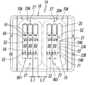
図1−図6には、本発明に係る防水型マニホールド電磁弁の第1実施形態が示されている。このマニホールド電磁弁1Aは、マニホールド10と、マニホールド10上に搭載された6個の電磁弁50と、電磁弁50を覆う2個の防水カバー70A,70Aとを有している。6個の電磁弁50は、2つの弁グループBG1,BG1に分けてマニホールド10上に搭載され、一方の弁グループBG1に属する3個の電磁弁50が、一方の防水カバー70Aでまとめて覆われ、他方の弁グループBG1に属する3個の電磁弁50が、他方の防水カバー70Aでまとめて覆われている。
1 to 6 show a first embodiment of a waterproof manifold solenoid valve according to the present invention. The
マニホールド10は、金属又は合成樹脂からなる単体型のマニホールドであって、一つの部材からなるマニホールド本体11と、このマニホールド本体11の一端及び他端にそれぞれガスケット13を介して取り付けられたエンドプレート12とにより構成されている。なお、以下の説明において、マニホールド10の縦方向とは、2つのエンドプレート12,12を結ぶ方向のことであって、長さ方向と同じであり、マニホールド10の横方向とは、縦方向に直交する方向のことであって、横幅方向と同じであり、マニホールド10の上下方向とは、高さ方向のことである。
マニホールド10の縦方向の両端面10a,10a及び横方向の両側面10b,10bは、マニホールド10の底面側に行くに従ってマニホールド10の長さ及び横幅が次第に拡大する方向(下広がり状)に傾斜している。
The
The longitudinal end faces 10a, 10a and the lateral side faces 10b, 10b of the
マニホールド本体11の内部には、中央の供給流路14と、供給流路14の両側に位置する2つの排出流路15A,15Bと、電気配線が収容されたダクト16とが、マニホールド本体11を縦方向に貫通するように形成され、これら供給流路14と排出流路15A,15B及びダクト16の両端は、ガスケット13とエンドプレート12とによって塞がれている。図中の符号28が付された部品は、エンドプレート12をマニホールド本体11の端面に固定するためのプレート固定螺子である。
Inside the manifold
供給流路14及び排出流路15A,15Bは、マニホールド本体11の縦方向一端寄りの位置で、マニホールド本体11の底面に開口する供給ポートP及び排出ポートEA,EBにそれぞれ連通し、ダクト16の内部には、マニホールド本体11の底面に接続された電気ケーブル17から延びる信号線及び給電線が収容され、電気ケーブル17は不図示の制御装置に接続されるようになっている。なお、この第1実施形態は、マニホールド電磁弁1Aの各電磁弁50と制御装置とを個別の信号線及び給電線で接続して、信号をパラレル伝送する例である。
The
マニホールド本体11の上面には、3個の電磁弁50を集合状態で搭載するための搭載エリア18Aが、マニホールド本体11の縦方向の2箇所に間隔をおいて形成され、各搭載エリア18Aに、それぞれ3つの弁搭載面19が、互いに近接した状態で並列に形成されている。そして、各弁搭載面19にそれぞれ1つの電磁弁50を、ガスケット51を介して搭載することにより、3個の電磁弁50が相互間に微小な弁間距離L1を保って平行に搭載された弁搭載部20Aが、2つ形成されている。図中の符号52は、電磁弁50をマニホールド本体11に固定するための電磁弁固定螺子を示し、同符号21は、電磁弁固定螺子52を螺着するためマニホールド本体11に形成された螺子孔を示している。
なお、弁搭載面19は、マニホールド本体11の横方向(幅方向)に細長く延在しているため、電磁弁50は、長さの方向をマニホールド本体11の幅方向に向けた姿勢で配設されていることになる。
また、2つの搭載エリア18A,18Aは、間隔をおいて互いに隔てられているため、2つの弁搭載部20A,20Aの互いに隣接する端部に位置する2つの電磁弁50,50は、弁間距離L1より大きい搭載部間距離L2で隔てられていることになる。
Since the
Further, since the two
3つの弁搭載面19は、互いに同じ構成を有するもので、各弁搭載面19には、1つの供給孔22と、供給孔22の両側に位置する2つの出力孔23A,23Bと、2つの出力孔23A,23Bの両外側に位置する2つの排出孔24A,24Bとが形成され、供給孔22は、供給流路14に連通すると共に、電磁弁50の下面の供給口53に連通し、2つの排出孔24A,24Bは、2つの排出流路15A,15Bに個別に連通すると共に、電磁弁50の下面の2つの排出口54A,54Bに個別に連通し、2つの出力孔23A,23Bは、マニホールド本体11の下面に形成された2つの出力ポートA,Bに個別に連通すると共に、電磁弁50の下面の2つの出力口55A,55Bに個別に連通している。
The three
また、6個の電磁弁50は、互いに同じ構成を有するダブルパイロット式の5ポート電磁弁であって、主弁部50aとパイロット弁部50bとを有している。
主弁部50aは、弁ボディ56と、弁ボディ56の内部に形成された弁孔57と、弁孔57内に摺動自在に収容されたスプール58と、弁ボディ56の一端及び他端に取り付けられたエンドブロック59及びマニュアルブロック60とを有し、エンドブロック59及びマニュアルブロック60の内部に、不図示のパイロットピストンがそれぞれ収容されている。
Further, the six
The
パイロット弁部50bには、電磁操作式の3ポート弁からなるパイロット弁62a,62bが上下に2つ設けられていて、パイロット弁部50bの下端部は、マニホールド本体11に形成された開口25を通じてダクト16内に進入し、ダクト16内の信号線及び給電線にパラレル接続されている。その接続は、電磁弁50をマニホールド10の弁搭載面19に搭載すると、不図示の電気接続具を介して自動的に行われるようになっている。
The
そして、一方のパイロット弁62aをオンにすると、パイロット流体の作用によりマニュアルブロック60の内部のパイロットピストンが駆動されてスプール58が図3の左方向に移動し、他方のパイロット弁62bをオンにすると、パイロット流体の作用によりエンドブロック59の内部のパイロットピストンが駆動されてスプール58が図3の右方向に移動し、このようなスプール58の往復動により、供給孔22と2つの出力孔23A,23Bとを結ぶ流路の接続状態、及び、2つの出力孔23A,23Bと2つの排出孔24A,24Bとを結ぶ流路の接続状態が、それぞれ切り換えられるようになっている。
Then, when one
また、マニュアルブロック60の上面には、パイロット弁による流路の切換状態を手動で実現させるための2つのマニュアルボタン61,61が、マニュアルブロック60の幅方向に並べて配設されている。
Further, on the upper surface of the
防水カバー70Aは、電磁弁50の長さ方向に細長い略長方形の平面視形状を有する部品であって、逆U字形の断面形状を有すると共に、長さ方向一端側及び他端側に位置する端壁71,71と、幅方向の一端側及び他端側に位置する側壁72,72と、上面壁73とを有している。2つの端壁71,71は、防水カバー70Aの長さ方向外側に向けて凸形の曲面をなし、また、2つの側壁72,72は、防水カバー70Aの長さ方向に真っ直ぐ延びる平坦面をなしていて、これら端壁71,71及び側壁72,72は、上面壁73側から防水カバー70Aの下端側に向けて次第に下広がり状をなす方向、換言すれば、防水カバー70Aの長さ方向の径及び幅方向の径が次第に拡大する方向に、それぞれ傾斜している。また、上面壁73は、防水カバー70Aの長さ方向にのみ外(上)に向けて凸の形に緩やかに湾曲している。2つの防水カバー70A,70Aは、互いに同一形状及び同一大きさを有している。
The
また、防水カバー70Aは、その長さ方向の一端部及び他端部であり且つ短手方向の中央部でもある2つの位置で、2つのカバー取付螺子74,74により、マニホールド10にガスケット75を介して固定されている。このためマニホールド10には、カバー取付螺子74,74を螺着するための螺子孔27が設けられている。
Further, the
更に、防水カバー70Aには、電磁弁50のマニュアルボタン61に対応する位置に矩形の操作孔76が形成され、この操作孔76に、矩形の孔カバー77が液密状態に取り付けられている。防水カバー70Aは3つの電磁弁50を覆っているため、操作孔76は3つ形成され、各操作孔76にそれぞれ孔カバー77が取り付けられている。
Furthermore, a
孔カバー77は、合成樹脂やゴムのような柔軟な素材で形成されていて、孔カバー77の外周に形成した係止溝77aに、操作孔76の孔縁76aを嵌合させて係止させることにより、操作孔76に着脱可能に取り付けられている。また、孔カバー77には、2つの柔軟な押圧部77bが上方に突出するように形成されると共に、各押圧部77bから下方に延出する2つの押し棒77cが、この押圧部77bと一体に形成されるか、又は別体に形成されて接続され、各押し棒77cの下端はそれぞれマニュアルボタン61に当接又は近接している。そして、押圧部77bを上から押すことにより、押し棒77bを介してマニュアルボタン61を操作することができるようになっている。この場合、2つの押圧部77bは、押圧時に別々に変形することができる程度に柔軟であることが必要である。
The
しかし、孔カバー77は、それを操作孔76から取り外してマニュアルボタン61を操作するように構成されていても良い。
However, the
防水カバー70Aは、透光性のある合成樹脂により、高温高圧の洗浄水やスチームジェット等の噴射に耐え得るような厚みに形成されている。しかし、防水カバー70Aは完全に透明である必要はなく、一部又は全部が着色されていても構わない。例えば、電磁弁50にインジケータランプが設けられている場合には、防水カバー70Aの少なくともインジケータランプに対応する部分を透明にすれば良い。
The
また、防水カバー70Aの表面は、食品滓やゴミ等の異物が付着しにくいようにして洗浄性を高めるため、全体として平滑で、カバー取付螺子74及び操作孔76以外の部分に凹凸が形成されていないような面にすることが望ましい。
同様の観点から、防水カバー70Aの大きさ、特に横幅Waは、隣接する防水カバー70A,70A間に、弁間距離L1より大きく且つマニホールド10の表面が外部に露出する大きさの隙間Sが形成されるような大きさであることが望ましい。
The surface of the
From the same viewpoint, the size of the
本実施形態においては、このように、合計6個の電磁弁50を、3個ずつ2つの弁グループBG1,BG1に分けてマニホールド10に搭載することにより、マニホールド10上の互いに離れた位置に、それぞれ3個の電磁弁が搭載された2つの弁搭載部20A,20Aを形成し、各弁搭載部20Aに、3個の電磁弁50を覆う小形の防水カバー70Aをそれぞれ取り付けているので、6個の電磁弁50全体を1つの大形の防水カバーでまとめて覆う場合に比べ、防水カバーの大形化に伴う強度低下や歪みの発生等の問題を解消することができると共に、防水カバーに補強用リブを形成するなどの強度保持のための対策を講じる必要もなくすことができる。
In the present embodiment, as described above, the six
図7には、本発明に係る防水型マニホールド電磁弁の第2実施形態が示されている。この第2実施形態のマニホールド電磁弁1Bは、全部で4個の電磁弁50を、それぞれ2個の電磁弁を有する2つの弁グループBG2,BG2に分けてマニホールド10上に搭載することにより、2個の電磁弁50が搭載された弁搭載部20Bを2つ形成し、各々の弁搭載部20Bに、2個の電磁弁50を覆う防水カバー70Bをそれぞれ取り付けたものである。従って、防水カバー70Bの数は、弁搭載部20Bの数と同じ2個であり、また、防水カバー70Bに形成された操作孔76の数も、防水カバー70Bが覆う電磁弁50の数と同じ2個である。更に、防水カバー70Bの横幅Wbは、第1実施形態で使用されている防水カバー70Aの横幅Waより小さい。
FIG. 7 shows a second embodiment of the waterproof manifold solenoid valve according to the present invention. In the
この第2実施形態のマニホールド電磁弁1Bは、電磁弁50の総数や、弁搭載部20Bの数、各弁搭載部20Bの電磁弁50の数、防水カバー70Bの横幅Wb等が、第1実施形態のマニホールド電磁弁1Aの場合と相違するが、それ以外の構成及び作用は、第1実施形態のマニホールド電磁弁1Aの場合と実質的に同じであるから、両者の主要な同一構成部分に第1実施形態に付した符号と同一の符号を付してこれ以上の説明は省略する。
In the
なお、第1実施形態のマニホールド電磁弁1Aにおいても、第2実施形態のマニホールド電磁弁1Bのように、6個の電磁弁50を、それぞれ2個の電磁弁50からなる3つの弁グループBG2に分けても良く、その場合には、3個の防水カバー70Bを使用することになる。しかし、部品数を減らしてコストを下げるという観点からは、好ましくは第1実施形態のように、6個の電磁弁50を3個ずつ2つの弁グループBG1に分け、2個の防水カバー70Aを使用するように構成することである。
Also in the
図8−図10には、本発明に係る防水型マニホールド電磁弁の第3実施形態が示されている。この第3実施形態のマニホールド電磁弁1Cは、第1実施形態と第2実施形態との折衷型であって、全部で7個の電磁弁50を、3個の電磁弁からなる1つの弁グループ(第1の弁グループ)BG1と、2個の電磁弁からなる2つの弁グループ(第2の弁グループ)BG2とに分け、マニホールド本体11には、3個の電磁弁50を搭載するための1つの搭載エリア(第1の搭載エリア)18Aと、2個の電磁弁50を搭載するための2つの搭載エリア(第2の搭載エリア)18Bとを形成し、各搭載エリア18A,18Bに3個又は2個の電磁弁50を搭載することにより、3個の電磁弁50が搭載された1つの弁搭載部(第1の弁搭載部)20Aと、2個の電磁弁50が搭載された2つの弁搭載部(第2の弁搭載部)20Bとを形成し、第1の弁搭載部20Aには、3個の電磁弁50を覆う防水カバー(第1の防水カバー)70Aを取り付け、第2の弁搭載部20Bには、2個の電磁弁50を覆う防水カバー(第2の防水カバー)70Bを取り付けたものである。
8 to 10 show a third embodiment of the waterproof manifold solenoid valve according to the present invention. The
また、マニホールド本体11の一端には、制御ブロック30が取り付けられ、制御ブロック30の内部には、シリアル・パラレル変換器80が収容され、制御ブロック30の上面には、各電磁弁50のアドレスを設定するためのアドレス設定器81が設置されると共に、このアドレス設定器81を覆う第3の防水カバー78が2つの螺子79で取り付けられ、制御ブロック30の下面には、制御装置からの信号線、給電線、及び接地線を接続するためのコネクタ82a,82b,82cが設けられている。制御ブロック30は、マニホールド本体11と一体であっても良い。
Further, the
そして、制御装置から送られるシリアル信号が、シリアル・パラレル変換器80でパラレル信号に変換され、このパラレル信号が、アドレス設定器81で指定されたアドレスに該当する電磁弁50に入力されることにより、この電磁弁50が作動するように構成されている。従って、この第3実施形態は、マニホールド電磁弁1Cと制御装置との間で信号をシリアル伝送する例である。
Then, the serial signal sent from the control device is converted into a parallel signal by the serial/
第3の防水カバー78の上面中央部には、アドレス設定器81を切換操作するための操作孔83が、防水カバー78の長さ方向に細長く延在するように形成され、この操作孔83に孔蓋84が、2つの蓋取付螺子85で着脱自在なるように取り付けられている。
なお、第3の防水カバー78は、第1の防水カバー70A及び第2の防水カバー70Bと比較して、横幅は若干相違しているが、長さ及び高さを含む外観形状は実質的に同一である。
The upper central portion of the third
The third
第3実施形態のマニホールド電磁弁1Cのその他の構成及び作用は、第1実施形態のマニホールド電磁弁1A及び第2実施形態のマニホールド電磁弁1Bと実質的に同じであるから、互いの主要な同一構成部分に第1及び第2実施形態に付した符号と同一の符号を付してその説明は省略する。
Other configurations and operations of the
なお、第3実施形態のマニホールド電磁弁1Cは、第1実施形態のマニホールド電磁弁1Aと同様に、信号をパラレル伝送する方式に変更することもでき、この場合には、制御ブロック30が不要になる。
その逆に、第1及び第2実施形態のマニホールド電磁弁1A,1Bを、シリアル伝送方式に変更することもでき、この場合には、マニホールド本体11に制御ブロック30が取り付けられる。
Note that the
On the contrary, the
第1−第3実施形態に示すマニホールド電磁弁1A,1B,1Cは、以下のような手順によってそれを得ることができる。
The
先ず、マニホールド10に搭載すべき電磁弁50の総数を決定する。その総数は4個以上である。
電磁弁50の総数が決まったら、この電磁弁50を、第1実施形態のように、3個の電磁弁からなる複数の弁グループ(第1の弁グループ)BG1に分けるか、又は、第2実施形態のように、2個の電磁弁からなる複数の弁グループ(第2の弁グループ)BG2に分けるか、あるいは、第3実施形態にょうに、第1の弁グループBG1及び第2の弁グループBG1がそれぞれ1つ以上混在するように分け、それにより、各弁グループの数を決定する。
First, the total number of
When the total number of the
次に、グループ分けした電磁弁50を搭載するため、マニホールド10に、第1実施形態のように、3個の電磁弁50を搭載するための第1の搭載エリア18Aを第1の弁グループBG1と同数形成するか、又は、第2実施形態のように、2個の電磁弁50を搭載するための第2の搭載エリア18Bを第2の弁グループBG2と同数形成するか、あるいは、第3実施形態のように、第1の搭載エリア18A及び第2の搭載エリア18Bを、第1の弁グループBG1の数及び第2の弁グループBG2の数とそれぞれ同数形成する。
Next, in order to mount the
また、3個の電磁弁50をまとめて覆う大きさを有する第1の防水カバー70A及び/又は2個の電磁弁50をまとめて覆う大きさを有する第2の防水カバー70Bを、第1の搭載エリア18A及び/又は第2の搭載エリア18Bの数と同数個用意する。
The first
続いて、マニホールド10の各々の搭載エリア18A又は18Bに3個又は2個の電磁弁50を搭載することにより、3個の電磁弁50が搭載された第1の弁搭載部20A及び/又は2個の電磁弁50が搭載された第2の弁搭載部20Bを形成する。
Subsequently, by mounting three or two
そして、マニホールド10の各々の弁搭載部20A,20Bに、当該弁搭載部に搭載されている3個又は2個の電磁弁50を覆うように防水カバー70A,70Bをそれぞれ取り付けることにより、所期の防水型マニホールド電磁弁1A,1B,1Cが得られる。
Then, by attaching the
各実施形態では、電磁弁50がダブルパイロット式の5ポート電磁弁であるが、この電磁弁50は、シングルパイロット式であっても良く、4ポート弁あるいは3ポート弁であっても構わない。また、全ての電磁弁50が同一構成である必要もなく、異なる構成の電磁弁が混在していても良い。例えば、シングルパイロット式の電磁弁とダブルパイロット式の電磁弁とが混同していても、5ポート弁と3ポート弁とが混在していても良い。要するに、第1の防水カバー70A及び第2の防水カバー70Bの一方又は両方を使用して全ての電磁弁を覆うことができれば良いのである。
In each embodiment, the
また、各実施形態のマニホールド電磁弁1A,1B,1Cは、何れも単体型のマニホールドであって、1つのマニホールド本体11に全ての搭載エリア18A,18Bが形成されているが、このマニホールド本体11を、複数のマニホールドブロックを連結することにより形成しても良い。この場合には、各マニホールドブロックに、それぞれ1つ以上の第1の搭載エリア18A及び/又は1つ以上の第2の搭載エリア18Bが形成されていることになる。
Further, the
1A,1B,1C 防水型マニホールド電磁弁
18A 第1の搭載エリア
18B 第2の搭載エリア
20A 第1の弁搭載部
20B 第2の弁搭載部
50 電磁弁
61 マニホールドボタン
70A 第1の防水カバー
70B 第2の防水カバー
76 操作孔
77 孔カバー
BG1 第1の弁グループ
BG2 第2の弁グループ
L1 弁間距離
L2 搭載部間距離
S 隙間
1A, 1B, 1C Waterproof
Claims (9)
マニホールドの各々の弁搭載部に、当該弁搭載部に搭載されている3個又は2個の電磁弁を覆うようにそれぞれ取り付けられた防水カバー、
を有することを特徴とする防水型マニホールド電磁弁。 A first valve mounting portion in which three solenoid valves are mounted in parallel while maintaining a constant valve distance, and a second valve mounting portion in which two solenoid valves are mounted in parallel while maintaining the valve distance. Among the valve mounting parts of, a plurality of any one of the valve mounting parts, or having one or more of both valve mounting parts, the solenoid valves located at the ends of the adjacent valve mounting parts, A manifold separated by a mounting distance that is greater than the valve distance,
A waterproof cover attached to each valve mounting portion of the manifold so as to cover the three or two electromagnetic valves mounted on the valve mounting portion,
A waterproof type manifold solenoid valve having:
防水カバーは、マニュアルボタンに対応する位置に、マニュアルボタンを操作するための操作孔を有し、操作孔には孔カバーが取り付けられている、
ことを特徴とする請求項1から5の何れかに記載のマニホールド電磁弁。 The solenoid valve has a manual button for manual operation on the upper surface covered with a waterproof cover,
The waterproof cover has an operation hole for operating the manual button at a position corresponding to the manual button, and the hole cover is attached to the operation hole.
The manifold solenoid valve according to any one of claims 1 to 5, wherein:
マニホールドに搭載する全ての電磁弁を、3個の電磁弁からなる第1の弁グループ及び/又は2個の電磁弁からなる第2の弁グループに分けることにより、第1の弁グループの数及び/又は第2の弁グループの数を決める工程、
マニホールドに、3個の電磁弁を搭載するための第1の搭載エリア及び/又は2個の電磁弁を搭載するための第2の搭載エリアを、第1の弁グループの数及び/又は第2の弁グループの数とそれぞれ同数形成する工程、
マニホールドの各々の搭載エリアに3個又は2個の電磁弁を搭載することにより、3個の電磁弁が搭載された第1の弁搭載部及び/又は2個の電磁弁が搭載された第2の弁搭載部を形成する工程、
マニホールドの各々の弁搭載部に、当該弁搭載部に搭載されている3個又は2個の電磁弁を覆うように防水カバーをそれぞれ取り付ける工程、
を有することを特徴とする防水型マニホールド電磁弁の製造方法。 A method for obtaining a waterproof type manifold solenoid valve in which four or more solenoid valves and two or more waterproof covers for covering the solenoid valves are mounted on a manifold,
By dividing all solenoid valves mounted in the manifold into a first valve group consisting of three solenoid valves and/or a second valve group consisting of two solenoid valves, the number of first valve groups and And/or determining the number of second valve groups,
The manifold has a first mounting area for mounting three solenoid valves and/or a second mounting area for mounting two solenoid valves, the number of first valve groups and/or the second mounting area. Forming the same number of valve groups as
By mounting three or two solenoid valves in each mounting area of the manifold, a first valve mounting portion in which three solenoid valves are mounted and/or a second valve in which two solenoid valves are mounted The step of forming the valve mounting part of
Attaching a waterproof cover to each valve mounting portion of the manifold so as to cover the three or two electromagnetic valves mounted on the valve mounting portion,
A method for manufacturing a waterproof manifold solenoid valve, comprising:
Priority Applications (10)
| Application Number | Priority Date | Filing Date | Title |
|---|---|---|---|
| JP2017031324A JP6732203B2 (en) | 2017-02-22 | 2017-02-22 | Waterproof manifold solenoid valve |
| BR112019017491-5A BR112019017491A2 (en) | 2017-02-22 | 2018-02-06 | ELECTROMAGNETIC VALVE OF WATER PROOF COLLECTOR |
| KR1020197024778A KR102507998B1 (en) | 2017-02-22 | 2018-02-06 | Watertight type manifold solenoid valve |
| MX2019009855A MX2019009855A (en) | 2017-02-22 | 2018-02-06 | Waterproof manifold electromagnetic valves. |
| RU2019129610A RU2019129610A (en) | 2017-02-22 | 2018-02-06 | WATERPROOF SOLENOID VALVE |
| US16/485,951 US11434939B2 (en) | 2017-02-22 | 2018-02-06 | Waterproof manifold electromagnetic valve |
| CN201880012993.0A CN110392801A (en) | 2017-02-22 | 2018-02-06 | Water proof type manifold solenoid valve |
| PCT/JP2018/003890 WO2018155153A1 (en) | 2017-02-22 | 2018-02-06 | Waterproof manifold electromagnetic valves |
| EP18757667.3A EP3587879B1 (en) | 2017-02-22 | 2018-02-06 | Waterproof manifold electromagnetic valves |
| TW107104253A TWI756360B (en) | 2017-02-22 | 2018-02-07 | Water-proof type manifold electromagnetic valve |
Applications Claiming Priority (1)
| Application Number | Priority Date | Filing Date | Title |
|---|---|---|---|
| JP2017031324A JP6732203B2 (en) | 2017-02-22 | 2017-02-22 | Waterproof manifold solenoid valve |
Publications (3)
| Publication Number | Publication Date |
|---|---|
| JP2018135963A JP2018135963A (en) | 2018-08-30 |
| JP2018135963A5 JP2018135963A5 (en) | 2019-09-26 |
| JP6732203B2 true JP6732203B2 (en) | 2020-07-29 |
Family
ID=63253162
Family Applications (1)
| Application Number | Title | Priority Date | Filing Date |
|---|---|---|---|
| JP2017031324A Active JP6732203B2 (en) | 2017-02-22 | 2017-02-22 | Waterproof manifold solenoid valve |
Country Status (10)
| Country | Link |
|---|---|
| US (1) | US11434939B2 (en) |
| EP (1) | EP3587879B1 (en) |
| JP (1) | JP6732203B2 (en) |
| KR (1) | KR102507998B1 (en) |
| CN (1) | CN110392801A (en) |
| BR (1) | BR112019017491A2 (en) |
| MX (1) | MX2019009855A (en) |
| RU (1) | RU2019129610A (en) |
| TW (1) | TWI756360B (en) |
| WO (1) | WO2018155153A1 (en) |
Families Citing this family (1)
| Publication number | Priority date | Publication date | Assignee | Title |
|---|---|---|---|---|
| JP2022139091A (en) | 2021-03-11 | 2022-09-26 | Smc株式会社 | Waterproof type electromagnetic valve |
Family Cites Families (12)
| Publication number | Priority date | Publication date | Assignee | Title |
|---|---|---|---|---|
| US3504704A (en) | 1968-04-29 | 1970-04-07 | Beckett Harcum Co | Valve and control assembly |
| US4757943A (en) | 1984-12-24 | 1988-07-19 | Naiad Company Usa | Method and apparatus for controlling the temperature of a liquid |
| DE9411684U1 (en) | 1994-07-19 | 1994-09-15 | Elco Kloeckner Heiztech Gmbh | Control device for a heating or cooling circuit |
| DE19535235A1 (en) | 1995-09-22 | 1997-03-27 | Bosch Gmbh Robert | Hydraulic unit |
| DE50010393D1 (en) | 2000-01-25 | 2005-06-30 | Festo Ag & Co | valve assembly |
| US6715510B2 (en) | 2002-06-10 | 2004-04-06 | Eaton Corporation | Electro-hydraulic controller for automatic transmissions |
| JP4058531B2 (en) | 2002-06-11 | 2008-03-12 | Smc株式会社 | Unit manifold valve |
| JP4224862B2 (en) * | 2006-10-12 | 2009-02-18 | Smc株式会社 | Valve device |
| US7543957B1 (en) | 2008-01-29 | 2009-06-09 | General Electric Company | Thermal management of LEDS integrated to compact fluorescent lamps |
| JP5418818B2 (en) | 2009-05-11 | 2014-02-19 | Smc株式会社 | Manifold made of amorphous resin |
| JP5467194B2 (en) * | 2010-07-30 | 2014-04-09 | Smc株式会社 | Integrated manifold valve for mounting multiple valves |
| CN204922152U (en) | 2014-03-18 | 2015-12-30 | 卡特彼勒公司 | Valve gap body and main valve casing |
-
2017
- 2017-02-22 JP JP2017031324A patent/JP6732203B2/en active Active
-
2018
- 2018-02-06 MX MX2019009855A patent/MX2019009855A/en unknown
- 2018-02-06 BR BR112019017491-5A patent/BR112019017491A2/en not_active IP Right Cessation
- 2018-02-06 KR KR1020197024778A patent/KR102507998B1/en active IP Right Grant
- 2018-02-06 US US16/485,951 patent/US11434939B2/en active Active
- 2018-02-06 CN CN201880012993.0A patent/CN110392801A/en active Pending
- 2018-02-06 EP EP18757667.3A patent/EP3587879B1/en active Active
- 2018-02-06 WO PCT/JP2018/003890 patent/WO2018155153A1/en unknown
- 2018-02-06 RU RU2019129610A patent/RU2019129610A/en not_active Application Discontinuation
- 2018-02-07 TW TW107104253A patent/TWI756360B/en active
Also Published As
| Publication number | Publication date |
|---|---|
| TW201840946A (en) | 2018-11-16 |
| KR20190120213A (en) | 2019-10-23 |
| EP3587879A4 (en) | 2020-11-25 |
| KR102507998B1 (en) | 2023-03-09 |
| RU2019129610A (en) | 2021-03-23 |
| EP3587879A1 (en) | 2020-01-01 |
| BR112019017491A2 (en) | 2020-03-31 |
| TWI756360B (en) | 2022-03-01 |
| US20200049169A1 (en) | 2020-02-13 |
| WO2018155153A1 (en) | 2018-08-30 |
| JP2018135963A (en) | 2018-08-30 |
| US11434939B2 (en) | 2022-09-06 |
| RU2019129610A3 (en) | 2021-06-22 |
| EP3587879B1 (en) | 2024-01-24 |
| MX2019009855A (en) | 2019-10-15 |
| CN110392801A (en) | 2019-10-29 |
Similar Documents
| Publication | Publication Date | Title |
|---|---|---|
| JP5467194B2 (en) | Integrated manifold valve for mounting multiple valves | |
| JP4697672B2 (en) | Manifold type solenoid valve device with stop valve | |
| JP4058531B2 (en) | Unit manifold valve | |
| JP2007032831A (en) | Manifold type solenoid valve assembly | |
| KR100912475B1 (en) | Valve apparatus | |
| JP6732203B2 (en) | Waterproof manifold solenoid valve | |
| EP0957300A2 (en) | Manifold for change-over valve | |
| JP5464440B2 (en) | Multiple solenoid valve | |
| US5996610A (en) | Solenoid-operated valve assembly | |
| US10900581B2 (en) | Manifold base for electromagnetic valve and manifold-type electromagnetic valve | |
| CN109764161A (en) | Combined-type sheet-type slide valve system and combined method | |
| KR20110003694U (en) | Solenoide-operated valve assembly for manifold | |
| PL60295B1 (en) | ||
| JP2021162029A (en) | Distribution valve and method for manufacturing distribution valve | |
| JP2002122260A (en) | Solenoid valve manifold | |
| WO2013150933A1 (en) | Valve structure |
Legal Events
| Date | Code | Title | Description |
|---|---|---|---|
| A521 | Request for written amendment filed |
Free format text: JAPANESE INTERMEDIATE CODE: A523 Effective date: 20190815 |
|
| A621 | Written request for application examination |
Free format text: JAPANESE INTERMEDIATE CODE: A621 Effective date: 20190815 |
|
| TRDD | Decision of grant or rejection written | ||
| A01 | Written decision to grant a patent or to grant a registration (utility model) |
Free format text: JAPANESE INTERMEDIATE CODE: A01 Effective date: 20200526 |
|
| A61 | First payment of annual fees (during grant procedure) |
Free format text: JAPANESE INTERMEDIATE CODE: A61 Effective date: 20200618 |
|
| R150 | Certificate of patent or registration of utility model |
Ref document number: 6732203 Country of ref document: JP Free format text: JAPANESE INTERMEDIATE CODE: R150 |
|
| R255 | Notification that request for automated payment was rejected |
Free format text: JAPANESE INTERMEDIATE CODE: R2525 |
|
| R250 | Receipt of annual fees |
Free format text: JAPANESE INTERMEDIATE CODE: R250 |