EP2237972B1 - Laufstift für eine rolle - Google Patents
Laufstift für eine rolle Download PDFInfo
- Publication number
- EP2237972B1 EP2237972B1 EP08871836A EP08871836A EP2237972B1 EP 2237972 B1 EP2237972 B1 EP 2237972B1 EP 08871836 A EP08871836 A EP 08871836A EP 08871836 A EP08871836 A EP 08871836A EP 2237972 B1 EP2237972 B1 EP 2237972B1
- Authority
- EP
- European Patent Office
- Prior art keywords
- housing
- pin
- caster
- ring
- roller
- Prior art date
- Legal status (The legal status is an assumption and is not a legal conclusion. Google has not performed a legal analysis and makes no representation as to the accuracy of the status listed.)
- Active
Links
Images
Classifications
-
- B—PERFORMING OPERATIONS; TRANSPORTING
- B60—VEHICLES IN GENERAL
- B60B—VEHICLE WHEELS; CASTORS; AXLES FOR WHEELS OR CASTORS; INCREASING WHEEL ADHESION
- B60B33/00—Castors in general ; Anti-clogging castors
- B60B33/0002—Castors in general ; Anti-clogging castors assembling to the object, e.g. furniture
-
- B—PERFORMING OPERATIONS; TRANSPORTING
- B60—VEHICLES IN GENERAL
- B60B—VEHICLE WHEELS; CASTORS; AXLES FOR WHEELS OR CASTORS; INCREASING WHEEL ADHESION
- B60B33/00—Castors in general ; Anti-clogging castors
- B60B33/0002—Castors in general ; Anti-clogging castors assembling to the object, e.g. furniture
- B60B33/0005—Castors in general ; Anti-clogging castors assembling to the object, e.g. furniture characterised by mounting method
- B60B33/001—Castors in general ; Anti-clogging castors assembling to the object, e.g. furniture characterised by mounting method by snapping, clicking or latching in
-
- B—PERFORMING OPERATIONS; TRANSPORTING
- B60—VEHICLES IN GENERAL
- B60B—VEHICLE WHEELS; CASTORS; AXLES FOR WHEELS OR CASTORS; INCREASING WHEEL ADHESION
- B60B33/00—Castors in general ; Anti-clogging castors
- B60B33/0002—Castors in general ; Anti-clogging castors assembling to the object, e.g. furniture
- B60B33/0015—Castors in general ; Anti-clogging castors assembling to the object, e.g. furniture characterised by adaptations made to castor
- B60B33/0021—Castors in general ; Anti-clogging castors assembling to the object, e.g. furniture characterised by adaptations made to castor in the form of a mounting pin
Definitions
- the invention relates to a role, in particular furniture role, with a housing which is rotatably mounted by means of a vertically disposed in an opening of the housing raceway pin on an object to be supported by the roller, wherein the running pin a first, arranged in the opening of the housing lot and a second, the housing has superior game.
- Rolls of the type mentioned are attached to the housing projecting over the raceway in a blind hole of the object to be worn, for example, a chair cross of an office chair.
- the housing of the raceway projecting beyond the housing has an annular groove in which a resilient retaining ring is arranged with a slightly larger diameter than the blind hole.
- the race of the raceway projecting beyond the housing is inserted into the blind hole, wherein the retaining ring is radially compressed and the roller is frictionally held on the object.
- the retaining ring has a certain axial and radial clearance relative to the annular groove of the running pin.
- the present invention seeks to provide a roller with a rolling pin, which can be easily manufactured and permanently inserted without play in a blind hole of an object to be worn.
- the invention is based above all on the recognition that a ring-in-groove solution is the most cost-effective option for a practical, releasable connection between the roller and the object to be supported.
- a ring-in-groove solution is the most cost-effective option for a practical, releasable connection between the roller and the object to be supported.
- at least two ring grooves arranged at a distance from each other are provided in the housing of the running pin projecting beyond the housing, in each of which an elastic retaining ring is arranged without play.
- one groove in the upper third and the at least one further groove in the lower third of the housing projecting portion of the runner pin is arranged.
- these are advantageously arranged at approximately equal distances from each other and the ends of the lot.
- the elastic retaining ring can be an open spring snap ring made of steel or plastic or an O-ring made of rubber or another elastomer. Since it would be comparatively complicated to match the width of the groove, ie the axial distance of the groove flanks from each other, and the wire diameter of a flat spring steel snap ring so precisely that would achieve backlash, the groove in a preferred embodiment of the invention has a greater width as the wire diameter of the open Federsprengrings and this is formed both axially and radially as a spring and is supported with end portions of the opposite flanks of the annular groove.
- the spring snap ring In order to enable a radial mounting of the spring snap ring, it expediently has a circumferential extent of 250 ° to 300 °, preferably about 270 °. It can then be easily snapped laterally into the groove. If the retaining ring is a self-contained rubber O-ring or other suitable elastomer, it is pushed axially over the end of the raceway pin into the corresponding groove.
- the two retaining rings expediently a lower clamping force, preferably about half, of the previously used retaining rings.
- This can be achieved for example by a reduced wire thickness, so for example, a wire thickness of 1.2 mm instead of the previous 1.5 mm.
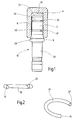
- the in Fig. 1 illustrated running pin 10 a not-shown role of a well-known type is arranged with a lot 12 in a blind hole 14 of a roller-to-carry object 16, for example, the base of an office chair.
- the portion 12 of the race pin 10 extends to a collar 18 approximately in the center of the pin and is the lot that projects beyond the housing of the roller, while the further portion 20 of the pin is so inserted into a vertically oriented opening of the roller housing, that the housing can rotate around the lot 20.
- the lot 12 has immediately after the collar 18 on a support cone 20 which serves as a stop for the edge of the blind hole 14 and limits the axial immersion of the lot 12 in the blind hole 14, so that between the end 24 of the lot 12 and the Floor 26 of the blind hole 14 remains a distance of a few millimeters.
- the lot 12 has two grooves 28, 28 ', in each of which a designed as an open spring snap ring retaining ring 30, 30' ( Fig. 2 ) is arranged.
- the axial extent of the relaxed retaining rings 30, 30 ' is greater than the distances of the flanks of the grooves 28, 28' from each other, so that the rings after insertion into the grooves with their open ends 32, 32 'in the grooves brace.
- rings 30, 30 ' can also be used appropriately designed plastic rings or O-rings made of rubber or other elastomer, either in pairs or with each other, ie, for example, a retaining ring 30 in a groove 28, 28' with an O-ring in the other groove are combined.
- the invention relates to a role, in particular furniture role, with a housing which is rotatably mounted by means of a vertically disposed in an opening of the housing raceway pin 10 to be supported by the roller article 16, wherein the running pin 10 is a first, in the portion of the housing disposed portion 20 and a second, the housing projecting portion 12 has.
Landscapes
- Engineering & Computer Science (AREA)
- Mechanical Engineering (AREA)
- Rolls And Other Rotary Bodies (AREA)
- Pivots And Pivotal Connections (AREA)
- Springs (AREA)
- Pinball Game Machines (AREA)
- Rolling Contact Bearings (AREA)
- Snaps, Bayonet Connections, Set Pins, And Snap Rings (AREA)
- Legs For Furniture In General (AREA)
Description
- Die Erfindung betrifft eine Rolle, insbesondere Möbelrolle, mit einem Gehäuse das mittels eines senkrecht in einer Öffnung des Gehäuses angeordneten Laufstifts an einem von der Rolle zu tragenden Gegenstand drehbar befestigt ist, wobei der Laufstift eine erste, in der Öffnung des Gehäuses angeordnete Partie und eine zweite, das Gehäuse überragende Partie aufweist.
- Rollen der genannten Art werden mit der das Gehäuse überragenden Partie des Laufstifts in einem Sackloch des zu tragenden Gegenstands, beispielsweise einem Stuhlkreuz eines Bürostuhls, befestigt. Hierzu weist die das Gehäuse überragende Partie des Laufstifts eine Ringnut auf, in der ein federnder Haltering mit einem geringfügig größeren Durchmesser als das Sackloch angeordnet ist. Die das Gehäuse überragende Partie des Laufstifts wird in das Sackloch eingesteckt, wobei der Haltering radial komprimiert und die Rolle kraftschlüssig an dem Gegenstand gehalten wird. Der Haltering weist gegenüber der Ringnut des Laufstifts jedoch ein gewisses axiales und radiales Spiel auf. Wird nun beispielsweise ein Bürostuhl über einen Boden mit Unebenheiten, wie einen Fliesenboden, gerollt, so kann sich der Laufstift im Rahmen des vorhandenen Spiels innerhalb des Sacklochs auf und ab bewegen sowie eine Taumelbewegung ausführe Dies führt zu einer störenden, klingelartigen Geräuschentwicklung. Aus der gattungsgmässen
EP-A-1 527 905 ist eine Rolle bekannt, deren Laufstift aus diesem Grund einen Haltering spielfrei in einer Nut einklemmt, die durch einen Absatz im Stift und eine gegenüber dem Absatz auf das Stiftende aufgesetzte Buchse aus Kunststoff gebildet ist. Sowohl der spielfreie Haltering als auch die Kunststoffbuchse sollen die unerwünschte Geräuschbildung unterdrücken. Zum einen ist die Herstellung eines derartigen Laufstifts jedoch recht aufwändig und zum anderen unterliegt die Kunststoffbuchse nach einiger Zeit einem gewissen Verschleiß, so dass der Haltering nicht mehr spielfrei in der Nut sitzt und der Laufstift wieder Spiel in dem Sackloch aufweist. - Ausgehend hiervon liegt der vorliegenden Erfindung die Aufgabe zugrunde, eine Rolle mit einem Laufstift bereitzustellen, der auf einfache Weise hergestellt und dauerhaft spielfrei in ein Sackloch eines zu tragenden Gegenstands eingesetzt werden kann.
- Zur Lösung dieser Aufgabe wird die im Patentanspruch 1 angegebene Merkmalskombination vorgeschlagen. Vorteilhafte Ausgestaltungen und Weiterbildungen der Erfindung ergeben sich aus den abhängigen Ansprüchen.
- Die Erfindung geht vor allem von der Erkenntnis aus, dass eine Ring-in-Nut Lösung die kostengünstigste Möglichkeit für eine praxisgerechte, lösbare Verbindung zwischen der Rolle und dem zu tragenden Gegenstand ist. Um axiale und radiale Bewegungen des Laufstifts in dem Sackloch dauerhaft zu unterbinden, wird gemäß der Erfindung daher vorgeschlagen, dass in der das Gehäuse überragenden Partie des Laufstifts mindestens zwei im Abstand voneinander angeordnete Ringnuten vorgesehen sind, in denen jeweils ein elastischer Haltering spielfrei angeordnet ist. Durch die Verwendung von zwei im Abstand voneinander angeordneten Halteringen wird eine Taumelbewegung des Laufstifts im Sackloch verhindert, durch die spielfreie Anordnung der Halteringe eine axiale Bewegung. Um eine wirksame Abstützung zu erreichen, ist die eine Nut im oberen Drittel und die mindestens eine weitere Nut im unteren Drittel der das Gehäuse überragenden Partie des Laufstifts angeordnet. Bei mehr als zwei Nuten werden diese vorteilhaft in etwa gleichen Abständen zueinander und den Enden der Partie angeordnet.
- Um die Spielfreiheit des Halterings in seiner Nut zu erreichen, kann der elastische Haltering ein offener Federsprengring aus Stahl oder Kunststoff oder ein O-Ring aus Gummi oder einem anderen Elastomer sein. Da es vergleichsweise aufwändig wäre, die Breite der Nut, also den axialen Abstand der Nutflanken voneinander, und den Drahtdurchmesser eines ebenen Federsprengrings aus Stahl so exakt aufeinander abzustimmen, dass eine Spielfreiheit erreichen würde, weist die Nut in bevorzugter Ausgestaltung der Erfindung eine größere Breite auf als der Drahtdurchmesser des offenen Federsprengrings und dieser ist sowohl axial als auch radial als Feder ausgebildet und stützt sich mit Endpartien an den gegenüberliegenden Flankender Ringnut ab.
- Um eine radiale Montage des Federsprengrings zu ermöglichen, weist er zweckmäßig eine Umfangserstreckung von 250° bis 300°, bevorzugt etwa 270° auf. Er kann dann auf einfache Weise seitlich in die Nut geschnappt werden. Ist der Haltering ein in sich geschlossener O-Ring aus Gummi oder einem anderen geeigneten Elastomer, so wird er axial über das Ende des Laufstifts in die entsprechende Nut geschoben.
- Um die Montage- und Demontagekraft im bisherigen Rahmen zu halten, weisen die zwei Halteringe zweckmäßig eine geringere Spannkraft, vorzugsweise etwa die Hälfte, der bisher verwendeten Halteringe auf. Dies kann zum Beispiel durch eine reduzierte Drahtstärke erreicht werden, also beispielsweise eine Drahtstärke von 1,2 mm anstatt der bisherigen 1,5 mm.
- Im Folgenden wird die Erfindung anhand der in der Zeichnung in schematischer Weise dargestellten Ausführungsbeispiele näher erläutert. Es zeigen
- Fig. 1
- einen Laufstift für eine Rolle mit zwei Halteringen; und
- Fig. 2
- zwei perspektivische Ansichten der Halteringe gemäß
Fig. 1 . - Der in
Fig. 1 dargestellte Laufstift 10 einer nicht näher dargestellten Rolle allgemein bekannter Art ist mit einer Partie 12 in einem Sackloch 14 eines von der Rolle zu tragenden Gegenstands 16, beispielsweise dem Fußkreuz eines Bürostuhls, angeordnet. Die Partie 12 des Laufstifts 10 erstreckt sich bis zu einem Bund 18 etwa in der Mitte des Stifts und ist die Partie, die über das Gehäuse der Rolle übersteht, während die weitere Partie 20 des Stifts derart in eine vertikal ausgerichtete Öffnung des Rollengehäuses eingesteckt ist, dass sich das Gehäuse um die Partie 20 drehen kann. Die Partie 12 weist unmittelbar im Anschluss an den Bund 18 einen Stützkonus 20 auf, der als Anschlag für den Rand des Sacklochs 14 dient und das axiale Eintauchen der Partie 12 in das Sackloch 14 begrenzt, so dass zwischen dem Ende 24 der Partie 12 und dem Boden 26 des Sacklochs 14 ein Abstand von einigen Millimetern verbleibt. - Die Partie 12 weist zwei Nuten 28, 28' auf, in denen jeweils ein als offener Federsprengring ausgebildeter Haltering 30, 30' (
Fig. 2 ) angeordnet ist. Die Nuten 28, 28' sind im Abstand voneinander etwa im oberen und im unteren Drittel der Partie 12 angeordnet. Die Halteringe 30, 30' sind derart aus einem Federdraht gebogen, dass sie sowohl als axiale als auch als radiale Federn wirken. Die axiale Ausdehnung der entspannten Halteringe 30, 30' ist größer als die Abstände der Flanken der Nuten 28, 28' voneinander, so dass sich die Ringe nach dem Einsetzen in die Nuten mit ihren offenen Enden 32, 32' in den Nuten verspannen. Auf diese Weise wird ein mögliches Axialspiel der Halteringe 30, 30' in den Nuten 28, 28' eliminiert. Die radiale Federkraft der Halteringe 30, 30' kommt beim Einstecken des Laufstifts 10 in das Sackloch 14 zum Tragen und sorgt für einen radial spielfreien Kraftschluss zwischen den Halteringen 30, 30' und der Innenwand des Sacklochs 14. Im Ergebnis weist der Laufstift 10 in dem Sackloch 14 weder axiales noch radiales Spiel auf. Störende Geräusche beim Überfahren unebener Böden können daher nicht entstehen. - Anstelle der in
Fig. 2 dargestellten Halteringe 30, 30' können auch entsprechend gestaltete Kunststoffringe oder O-Ringe aus Gummi oder einem anderen Elastomer verwendet werden, entweder paarweise oder untereinander kombiniert, d.h. es kann beispielsweise ein Haltering 30 in einer Nut 28, 28' mit einem O-Ring in der anderen Nut kombiniert werden. - Zusammenfassend ist folgendes festzuhalten: Die Erfindung betrifft eine Rolle, insbesondere Möbelrolle, mit einem Gehäuse das mittels eines senkrecht in einer Öffnung des Gehäuses angeordneten Laufstifts 10 an einem von der Rolle zu tragenden Gegenstand 16 drehbar befestigt ist, wobei der Laufstift 10 eine erste, in der Öffnung des Gehäuses angeordnete Partie 20 und eine zweite, das Gehäuse überragende Partie 12 aufweist. Um auf einfache und kostengünstige Weise einen Laufstift zu schaffen, der dauerhaft eine störende Geräuschentwicklung durch Relativbewegungen zwischen dem Laufstift und dem zu tragenden Gegenstand unterbindet, wird gemäß der Erfindung vorgeschlagen, dass in der das Gehäuse überragenden Partie 12 des Laufstifts 10 mindestens zwei im Abstand voneinander angeordnete Ringnuten 28, 28' vorgesehen sind, in denen jeweils ein elastischer Haltering 30, 30' spielfrei angeordnet ist.
Claims (4)
- Rolle, insbesondere Möbelrolle, mit einem Gehäuse das mittels eines senkrecht in einer Öffnung des Gehäuses angeordneten Laufstifts (10) an einem von der Rolle zu tragenden Gegenstand (16) drehbar befestigt ist, wobei der Laufstift (10) eine erste, in der Öffnung des Gehäuses angeordnete Partie (20) und eine zweite, das Gehäuse überragende Partie (12) aufweist, dadurch gekennzeichnet, dass in der das Gehäuse überragenden Partie (12) des Laufstifts (10) mindestens zwei im Abstand voneinander angeordnete Ringnuten (28, 28') vorgesehen sind, in denen jeweils ein elastischer Haltering (30, 30') spielfrei angeordnet ist.
- Rolle nach Anspruch 1, dadurch gekennzeichnet, dass der elastische Haltering (30, 30') ein offener Federsprengring aus Stahl oder Kunststoff oder ein O-Ring aus Gummi oder einem anderen Elastomer ist.
- Rolle nach Anspruch 2, dadurch gekennzeichnet, dass sich der als offener Federsprengring aus Stahl ausgebildete Haltering (30, 30') mit Endpartien (32, 32') an gegenüberliegenden Flanken der Ringnut (28, 28') abstützt.
- Rolle nach Anspruch 2 oder 3, dadurch gekennzeichnet, dass der Federsprengring (30, 30') eine Umfangserstreckung von 250° bis 300°, bevorzugt 270° aufweist.
Priority Applications (1)
| Application Number | Priority Date | Filing Date | Title |
|---|---|---|---|
| PL08871836T PL2237972T3 (pl) | 2008-02-01 | 2008-11-25 | Trzpień toczny dla rolki |
Applications Claiming Priority (2)
| Application Number | Priority Date | Filing Date | Title |
|---|---|---|---|
| DE102008007445A DE102008007445A1 (de) | 2008-02-01 | 2008-02-01 | Laufstift für eine Rolle |
| PCT/EP2008/066116 WO2009095123A1 (de) | 2008-02-01 | 2008-11-25 | Laufstift für eine rolle |
Publications (2)
| Publication Number | Publication Date |
|---|---|
| EP2237972A1 EP2237972A1 (de) | 2010-10-13 |
| EP2237972B1 true EP2237972B1 (de) | 2013-03-20 |
Family
ID=40343455
Family Applications (1)
| Application Number | Title | Priority Date | Filing Date |
|---|---|---|---|
| EP08871836A Active EP2237972B1 (de) | 2008-02-01 | 2008-11-25 | Laufstift für eine rolle |
Country Status (9)
| Country | Link |
|---|---|
| US (3) | US20100287730A1 (de) |
| EP (1) | EP2237972B1 (de) |
| CN (1) | CN101925475B (de) |
| DE (1) | DE102008007445A1 (de) |
| DK (1) | DK2237972T3 (de) |
| ES (1) | ES2404181T3 (de) |
| PL (1) | PL2237972T3 (de) |
| PT (1) | PT2237972E (de) |
| WO (1) | WO2009095123A1 (de) |
Cited By (1)
| Publication number | Priority date | Publication date | Assignee | Title |
|---|---|---|---|---|
| EP2857223A1 (de) * | 2013-08-19 | 2015-04-08 | Tente Roulettes Polymeres - Bruandet | Rolle für ein Möbelstück sowie ein Möbelstück mit entsprechender Rolle. |
Families Citing this family (8)
| Publication number | Priority date | Publication date | Assignee | Title |
|---|---|---|---|---|
| DE102008007445A1 (de) * | 2008-02-01 | 2009-08-06 | Gross + Froelich Gmbh & Co. Kg | Laufstift für eine Rolle |
| CN103790977A (zh) * | 2014-02-13 | 2014-05-14 | 杭叉集团股份有限公司 | 托盘车辅助轮回转支撑机构 |
| CN107062569A (zh) * | 2017-05-23 | 2017-08-18 | 珠海格力电器股份有限公司 | 脚轮安装结构、移动空调和除湿机 |
| CN107031286A (zh) * | 2017-05-23 | 2017-08-11 | 珠海格力电器股份有限公司 | 脚轮安装结构和移动空调 |
| US12030341B2 (en) | 2017-11-27 | 2024-07-09 | Omco Sumo, Inc. | Caster braking system technology |
| US11498360B2 (en) | 2019-05-21 | 2022-11-15 | Ngs Capital Management, Llc | Hybrid bearing arrangement caster technology |
| USD1035424S1 (en) * | 2022-06-16 | 2024-07-16 | Benyu Casters & Wheels Co., Ltd | Caster with brake |
| US12447773B1 (en) * | 2025-03-10 | 2025-10-21 | Haiyan Wang | Wheel assembly |
Family Cites Families (34)
| Publication number | Priority date | Publication date | Assignee | Title |
|---|---|---|---|---|
| US134350A (en) * | 1872-12-31 | Improvement in furniture-casters | ||
| US972871A (en) * | 1910-01-15 | 1910-10-18 | Diamond Steel Truck Company | Furniture-caster. |
| US973514A (en) * | 1910-01-15 | 1910-10-25 | Diamond Steel Truck Company | Caster-socket. |
| US1442223A (en) * | 1919-12-22 | 1923-01-16 | Cleveland Steel Tool Company | Rivet set |
| US2963732A (en) * | 1958-09-09 | 1960-12-13 | Bassick Co | Caster having a compensator clip |
| US3249960A (en) * | 1965-01-06 | 1966-05-10 | Nagel Chase Mfg Company | Caster pintle |
| US3326580A (en) * | 1965-01-07 | 1967-06-20 | Worthington Corp | Locking assembly having means to prevent axial and torsional movement |
| US3687241A (en) * | 1971-04-15 | 1972-08-29 | Stewart Warner Corp | Caster brake |
| US4120071A (en) * | 1976-05-17 | 1978-10-17 | Stewart-Warner Corporation | Dual wheel caster |
| US4129921A (en) * | 1978-01-05 | 1978-12-19 | Shepherd Products U.S. Inc. | Plastic grip ring |
| US4361930A (en) * | 1979-11-16 | 1982-12-07 | Tiffany Industries, Inc. | Caster socket assembly |
| EP0060839A4 (de) * | 1980-09-22 | 1982-12-20 | Stewart Warner Corp | Schwenkbares rad mit einer das kippen verhindernden vorrichtung. |
| US4377883A (en) * | 1981-10-13 | 1983-03-29 | Plastiglide Manufacturing Corporation | Twin caster assembly |
| GB2182554B (en) * | 1985-09-20 | 1989-09-06 | Guy Raymond Eng Co Ltd | Spindle assembly |
| US4749204A (en) * | 1987-05-05 | 1988-06-07 | Luxor Corporation | Cart wheel structure |
| USD349043S (en) * | 1993-01-28 | 1994-07-26 | Metro Industries, Inc. | Caster |
| US5390394A (en) * | 1993-09-30 | 1995-02-21 | Huang; Ming T. | Detachable front wheel assembly for a stroller |
| US5568671A (en) * | 1994-12-01 | 1996-10-29 | Fki, Industries, Inc. | Caster assembly with integral plastic stem and horn and with removable axle lock cap |
| USD448278S1 (en) * | 2001-01-31 | 2001-09-25 | Ching-Hui Chi | Wheel assembly for an office chair |
| CN2468771Y (zh) * | 2001-02-15 | 2002-01-02 | 纪清辉 | 改良的办公椅轮组 |
| US7150070B2 (en) * | 2001-06-04 | 2006-12-19 | Donakowski William J | Hubless caster |
| USD457421S1 (en) * | 2001-06-15 | 2002-05-21 | Hon Technology Inc. | Castor |
| US20030150080A1 (en) * | 2002-02-14 | 2003-08-14 | Yao-Wei Yang | Caster with a structural improvement |
| USD470748S1 (en) * | 2002-09-16 | 2003-02-25 | Po-Chuan Tsai | Chair caster |
| US6748623B1 (en) * | 2002-11-27 | 2004-06-15 | Po-Chuan Tsai | Chair caster |
| ITBO20030112U1 (it) * | 2003-10-28 | 2005-04-29 | Emilsider Meccanica | Ruota auto-orientabile per lo scorrimento di mobili e simili |
| USD547639S1 (en) * | 2005-02-17 | 2007-07-31 | Bruandet Sa | Castor |
| USD561014S1 (en) * | 2005-12-12 | 2008-02-05 | Gross + Froelich Bmbh & Co. Kg | Castor |
| DE102008007445A1 (de) * | 2008-02-01 | 2009-08-06 | Gross + Froelich Gmbh & Co. Kg | Laufstift für eine Rolle |
| USD592490S1 (en) * | 2008-05-05 | 2009-05-19 | Jäcob Holtz Company | Caster |
| USD731878S1 (en) * | 2013-08-20 | 2015-06-16 | Sistema Plastics Limited | Wheel |
| USD735022S1 (en) * | 2014-03-19 | 2015-07-28 | Der Sheng Co. Ltd. | Caster |
| USD911828S1 (en) * | 2018-10-01 | 2021-03-02 | Reliable Production Machining & Welding | Flex fork wheel support assembly |
| USD901283S1 (en) * | 2020-07-06 | 2020-11-10 | Dongping Chen | Chair caster wheel |
-
2008
- 2008-02-01 DE DE102008007445A patent/DE102008007445A1/de not_active Withdrawn
- 2008-11-25 CN CN2008801256624A patent/CN101925475B/zh active Active
- 2008-11-25 ES ES08871836T patent/ES2404181T3/es active Active
- 2008-11-25 EP EP08871836A patent/EP2237972B1/de active Active
- 2008-11-25 PT PT88718366T patent/PT2237972E/pt unknown
- 2008-11-25 DK DK08871836.6T patent/DK2237972T3/da active
- 2008-11-25 US US12/735,480 patent/US20100287730A1/en not_active Abandoned
- 2008-11-25 PL PL08871836T patent/PL2237972T3/pl unknown
- 2008-11-25 WO PCT/EP2008/066116 patent/WO2009095123A1/de not_active Ceased
-
2018
- 2018-11-08 US US29/669,508 patent/USD955862S1/en active Active
- 2018-12-14 US US16/220,844 patent/US20190118578A1/en not_active Abandoned
Cited By (1)
| Publication number | Priority date | Publication date | Assignee | Title |
|---|---|---|---|---|
| EP2857223A1 (de) * | 2013-08-19 | 2015-04-08 | Tente Roulettes Polymeres - Bruandet | Rolle für ein Möbelstück sowie ein Möbelstück mit entsprechender Rolle. |
Also Published As
| Publication number | Publication date |
|---|---|
| CN101925475B (zh) | 2012-12-19 |
| US20190118578A1 (en) | 2019-04-25 |
| PL2237972T3 (pl) | 2013-08-30 |
| US20100287730A1 (en) | 2010-11-18 |
| DK2237972T3 (da) | 2013-04-15 |
| EP2237972A1 (de) | 2010-10-13 |
| DE102008007445A1 (de) | 2009-08-06 |
| ES2404181T3 (es) | 2013-05-24 |
| PT2237972E (pt) | 2013-04-26 |
| WO2009095123A1 (de) | 2009-08-06 |
| USD955862S1 (en) | 2022-06-28 |
| CN101925475A (zh) | 2010-12-22 |
Similar Documents
| Publication | Publication Date | Title |
|---|---|---|
| EP2237972A1 (de) | Laufstift für eine rolle | |
| EP2057383B1 (de) | Wälzlagereinheit | |
| WO2012110345A1 (de) | Wälzlager | |
| EP3403529B1 (de) | Ausziehführung | |
| WO2013017156A1 (de) | Lenksäule mit lenkungslager und lenkungslager einer lenksäule | |
| DE102013218434B4 (de) | Lagerung | |
| EP2863774B1 (de) | Auszugs-führungsvorrichtung für relativ zueinander bewegliche möbelteile mit einer wälzkörperlagereinrichtung | |
| DE102014219705A1 (de) | Lagerring | |
| WO2018133897A1 (de) | Vorrichtung zur drehmomententkopplung und axialen kopplung | |
| DE102005018244A1 (de) | Wälzlageranordnung | |
| DE102009013038B4 (de) | Tripodegelenkrolle und Tripodegelenk | |
| EP2406526B1 (de) | Planetenträger aus blech und planetenradeinheit mit mindestens einem planetenträger aus blech | |
| DE10226058B4 (de) | Teleskopführung | |
| EP2894048A1 (de) | Laufrolle insbesondere für Schiebetüren | |
| DE102005053622B4 (de) | Axial-Radial-Lager, insbesondere für einen Rundtisch einer Werkzeugmaschine | |
| EP3129666A1 (de) | Segmentlageranordnung mit reibschlussverbindung | |
| WO2009049956A1 (de) | Lageranordnung zur aufnahme radialer und axialer belastungen | |
| DE102009058569B4 (de) | Rollenanordnung | |
| DE1139066B (de) | Tragrollensatz fuer Foerderbaender | |
| DE2745826A1 (de) | Spielfreies waelzlager | |
| DE1956655A1 (de) | Lagervorrichtung | |
| AT404573B (de) | Rolle zur anbringung an möbeln od.dgl. | |
| DE1123442B (de) | Rollender Aufhaenger fuer Vorhaenge, Gardinen od. dgl. | |
| WO2017202404A1 (de) | Wälzlager für anwendungen mit wechselnden hohen und niedrigen lasten | |
| DE102015210940A1 (de) | Vorrichtung zur Lagerung von mindestens zwei Wellenelementen |
Legal Events
| Date | Code | Title | Description |
|---|---|---|---|
| PUAI | Public reference made under article 153(3) epc to a published international application that has entered the european phase |
Free format text: ORIGINAL CODE: 0009012 |
|
| 17P | Request for examination filed |
Effective date: 20100621 |
|
| AK | Designated contracting states |
Kind code of ref document: A1 Designated state(s): AT BE BG CH CY CZ DE DK EE ES FI FR GB GR HR HU IE IS IT LI LT LU LV MC MT NL NO PL PT RO SE SI SK TR |
|
| AX | Request for extension of the european patent |
Extension state: AL BA MK RS |
|
| DAX | Request for extension of the european patent (deleted) | ||
| GRAP | Despatch of communication of intention to grant a patent |
Free format text: ORIGINAL CODE: EPIDOSNIGR1 |
|
| GRAS | Grant fee paid |
Free format text: ORIGINAL CODE: EPIDOSNIGR3 |
|
| GRAA | (expected) grant |
Free format text: ORIGINAL CODE: 0009210 |
|
| AK | Designated contracting states |
Kind code of ref document: B1 Designated state(s): AT BE BG CH CY CZ DE DK EE ES FI FR GB GR HR HU IE IS IT LI LT LU LV MC MT NL NO PL PT RO SE SI SK TR |
|
| REG | Reference to a national code |
Ref country code: GB Ref legal event code: FG4D Free format text: NOT ENGLISH |
|
| REG | Reference to a national code |
Ref country code: CH Ref legal event code: EP |
|
| REG | Reference to a national code |
Ref country code: IE Ref legal event code: FG4D Free format text: LANGUAGE OF EP DOCUMENT: GERMAN |
|
| REG | Reference to a national code |
Ref country code: DK Ref legal event code: T3 Ref country code: AT Ref legal event code: REF Ref document number: 601825 Country of ref document: AT Kind code of ref document: T Effective date: 20130415 Ref country code: RO Ref legal event code: EPE |
|
| REG | Reference to a national code |
Ref country code: PT Ref legal event code: SC4A Free format text: AVAILABILITY OF NATIONAL TRANSLATION Effective date: 20130418 |
|
| REG | Reference to a national code |
Ref country code: SE Ref legal event code: TRGR |
|
| REG | Reference to a national code |
Ref country code: DE Ref legal event code: R096 Ref document number: 502008009554 Country of ref document: DE Effective date: 20130508 |
|
| REG | Reference to a national code |
Ref country code: ES Ref legal event code: FG2A Ref document number: 2404181 Country of ref document: ES Kind code of ref document: T3 Effective date: 20130524 |
|
| REG | Reference to a national code |
Ref country code: NL Ref legal event code: T3 |
|
| REG | Reference to a national code |
Ref country code: NO Ref legal event code: T2 Effective date: 20130320 |
|
| PG25 | Lapsed in a contracting state [announced via postgrant information from national office to epo] |
Ref country code: BG Free format text: LAPSE BECAUSE OF FAILURE TO SUBMIT A TRANSLATION OF THE DESCRIPTION OR TO PAY THE FEE WITHIN THE PRESCRIBED TIME-LIMIT Effective date: 20130620 Ref country code: LT Free format text: LAPSE BECAUSE OF FAILURE TO SUBMIT A TRANSLATION OF THE DESCRIPTION OR TO PAY THE FEE WITHIN THE PRESCRIBED TIME-LIMIT Effective date: 20130320 |
|
| REG | Reference to a national code |
Ref country code: LT Ref legal event code: MG4D |
|
| PG25 | Lapsed in a contracting state [announced via postgrant information from national office to epo] |
Ref country code: GR Free format text: LAPSE BECAUSE OF FAILURE TO SUBMIT A TRANSLATION OF THE DESCRIPTION OR TO PAY THE FEE WITHIN THE PRESCRIBED TIME-LIMIT Effective date: 20130621 Ref country code: LV Free format text: LAPSE BECAUSE OF FAILURE TO SUBMIT A TRANSLATION OF THE DESCRIPTION OR TO PAY THE FEE WITHIN THE PRESCRIBED TIME-LIMIT Effective date: 20130320 Ref country code: SI Free format text: LAPSE BECAUSE OF FAILURE TO SUBMIT A TRANSLATION OF THE DESCRIPTION OR TO PAY THE FEE WITHIN THE PRESCRIBED TIME-LIMIT Effective date: 20130320 |
|
| REG | Reference to a national code |
Ref country code: PL Ref legal event code: T3 |
|
| PG25 | Lapsed in a contracting state [announced via postgrant information from national office to epo] |
Ref country code: HR Free format text: LAPSE BECAUSE OF FAILURE TO SUBMIT A TRANSLATION OF THE DESCRIPTION OR TO PAY THE FEE WITHIN THE PRESCRIBED TIME-LIMIT Effective date: 20130320 |
|
| REG | Reference to a national code |
Ref country code: SK Ref legal event code: T3 Ref document number: E 14476 Country of ref document: SK |
|
| PG25 | Lapsed in a contracting state [announced via postgrant information from national office to epo] |
Ref country code: IS Free format text: LAPSE BECAUSE OF FAILURE TO SUBMIT A TRANSLATION OF THE DESCRIPTION OR TO PAY THE FEE WITHIN THE PRESCRIBED TIME-LIMIT Effective date: 20130720 Ref country code: EE Free format text: LAPSE BECAUSE OF FAILURE TO SUBMIT A TRANSLATION OF THE DESCRIPTION OR TO PAY THE FEE WITHIN THE PRESCRIBED TIME-LIMIT Effective date: 20130320 |
|
| PG25 | Lapsed in a contracting state [announced via postgrant information from national office to epo] |
Ref country code: CY Free format text: LAPSE BECAUSE OF FAILURE TO SUBMIT A TRANSLATION OF THE DESCRIPTION OR TO PAY THE FEE WITHIN THE PRESCRIBED TIME-LIMIT Effective date: 20130320 |
|
| PLBE | No opposition filed within time limit |
Free format text: ORIGINAL CODE: 0009261 |
|
| STAA | Information on the status of an ep patent application or granted ep patent |
Free format text: STATUS: NO OPPOSITION FILED WITHIN TIME LIMIT |
|
| 26N | No opposition filed |
Effective date: 20140102 |
|
| REG | Reference to a national code |
Ref country code: HU Ref legal event code: AG4A Ref document number: E018189 Country of ref document: HU |
|
| REG | Reference to a national code |
Ref country code: DE Ref legal event code: R097 Ref document number: 502008009554 Country of ref document: DE Effective date: 20140102 |
|
| PG25 | Lapsed in a contracting state [announced via postgrant information from national office to epo] |
Ref country code: MC Free format text: LAPSE BECAUSE OF FAILURE TO SUBMIT A TRANSLATION OF THE DESCRIPTION OR TO PAY THE FEE WITHIN THE PRESCRIBED TIME-LIMIT Effective date: 20130320 |
|
| PG25 | Lapsed in a contracting state [announced via postgrant information from national office to epo] |
Ref country code: HU Free format text: LAPSE BECAUSE OF NON-PAYMENT OF DUE FEES Effective date: 20131126 |
|
| PG25 | Lapsed in a contracting state [announced via postgrant information from national office to epo] |
Ref country code: LU Free format text: LAPSE BECAUSE OF NON-PAYMENT OF DUE FEES Effective date: 20131125 |
|
| PG25 | Lapsed in a contracting state [announced via postgrant information from national office to epo] |
Ref country code: MT Free format text: LAPSE BECAUSE OF FAILURE TO SUBMIT A TRANSLATION OF THE DESCRIPTION OR TO PAY THE FEE WITHIN THE PRESCRIBED TIME-LIMIT Effective date: 20130320 |
|
| REG | Reference to a national code |
Ref country code: FR Ref legal event code: PLFP Year of fee payment: 8 |
|
| REG | Reference to a national code |
Ref country code: FR Ref legal event code: PLFP Year of fee payment: 9 |
|
| REG | Reference to a national code |
Ref country code: FR Ref legal event code: PLFP Year of fee payment: 10 |
|
| PGFP | Annual fee paid to national office [announced via postgrant information from national office to epo] |
Ref country code: NO Payment date: 20191126 Year of fee payment: 12 Ref country code: RO Payment date: 20191025 Year of fee payment: 12 Ref country code: IE Payment date: 20191121 Year of fee payment: 12 Ref country code: SK Payment date: 20191024 Year of fee payment: 12 Ref country code: FI Payment date: 20191121 Year of fee payment: 12 |
|
| PGFP | Annual fee paid to national office [announced via postgrant information from national office to epo] |
Ref country code: BE Payment date: 20191120 Year of fee payment: 12 |
|
| REG | Reference to a national code |
Ref country code: FI Ref legal event code: MAE |
|
| REG | Reference to a national code |
Ref country code: NO Ref legal event code: MMEP |
|
| REG | Reference to a national code |
Ref country code: SK Ref legal event code: MM4A Ref document number: E 14476 Country of ref document: SK Effective date: 20201125 |
|
| PG25 | Lapsed in a contracting state [announced via postgrant information from national office to epo] |
Ref country code: FI Free format text: LAPSE BECAUSE OF NON-PAYMENT OF DUE FEES Effective date: 20201125 Ref country code: NO Free format text: LAPSE BECAUSE OF NON-PAYMENT OF DUE FEES Effective date: 20201130 Ref country code: RO Free format text: LAPSE BECAUSE OF NON-PAYMENT OF DUE FEES Effective date: 20201125 Ref country code: SK Free format text: LAPSE BECAUSE OF NON-PAYMENT OF DUE FEES Effective date: 20201125 |
|
| REG | Reference to a national code |
Ref country code: BE Ref legal event code: MM Effective date: 20201130 |
|
| PG25 | Lapsed in a contracting state [announced via postgrant information from national office to epo] |
Ref country code: IE Free format text: LAPSE BECAUSE OF NON-PAYMENT OF DUE FEES Effective date: 20201125 |
|
| PG25 | Lapsed in a contracting state [announced via postgrant information from national office to epo] |
Ref country code: BE Free format text: LAPSE BECAUSE OF NON-PAYMENT OF DUE FEES Effective date: 20201130 |
|
| REG | Reference to a national code |
Ref country code: CH Ref legal event code: U11 Free format text: ST27 STATUS EVENT CODE: U-0-0-U10-U11 (AS PROVIDED BY THE NATIONAL OFFICE) Effective date: 20251201 |
|
| PGFP | Annual fee paid to national office [announced via postgrant information from national office to epo] |
Ref country code: PT Payment date: 20251113 Year of fee payment: 18 |
|
| PGFP | Annual fee paid to national office [announced via postgrant information from national office to epo] |
Ref country code: NL Payment date: 20251119 Year of fee payment: 18 |
|
| PGFP | Annual fee paid to national office [announced via postgrant information from national office to epo] |
Ref country code: DE Payment date: 20251119 Year of fee payment: 18 |
|
| PGFP | Annual fee paid to national office [announced via postgrant information from national office to epo] |
Ref country code: GB Payment date: 20251121 Year of fee payment: 18 |
|
| PGFP | Annual fee paid to national office [announced via postgrant information from national office to epo] |
Ref country code: AT Payment date: 20251120 Year of fee payment: 18 |
|
| PGFP | Annual fee paid to national office [announced via postgrant information from national office to epo] |
Ref country code: IT Payment date: 20251121 Year of fee payment: 18 Ref country code: DK Payment date: 20251125 Year of fee payment: 18 |
|
| PGFP | Annual fee paid to national office [announced via postgrant information from national office to epo] |
Ref country code: FR Payment date: 20251121 Year of fee payment: 18 |
|
| PGFP | Annual fee paid to national office [announced via postgrant information from national office to epo] |
Ref country code: TR Payment date: 20251118 Year of fee payment: 18 |
|
| PGFP | Annual fee paid to national office [announced via postgrant information from national office to epo] |
Ref country code: SE Payment date: 20251119 Year of fee payment: 18 Ref country code: CH Payment date: 20251201 Year of fee payment: 18 |
|
| PGFP | Annual fee paid to national office [announced via postgrant information from national office to epo] |
Ref country code: CZ Payment date: 20251119 Year of fee payment: 18 |
|
| PGFP | Annual fee paid to national office [announced via postgrant information from national office to epo] |
Ref country code: PL Payment date: 20251114 Year of fee payment: 18 |
|
| PGFP | Annual fee paid to national office [announced via postgrant information from national office to epo] |
Ref country code: ES Payment date: 20251229 Year of fee payment: 18 |