EP2237830B1 - Valve connector for medical lines - Google Patents
Valve connector for medical lines Download PDFInfo
- Publication number
- EP2237830B1 EP2237830B1 EP09706949A EP09706949A EP2237830B1 EP 2237830 B1 EP2237830 B1 EP 2237830B1 EP 09706949 A EP09706949 A EP 09706949A EP 09706949 A EP09706949 A EP 09706949A EP 2237830 B1 EP2237830 B1 EP 2237830B1
- Authority
- EP
- European Patent Office
- Prior art keywords
- tubular element
- fitting
- internal
- external
- female fitting
- Prior art date
- Legal status (The legal status is an assumption and is not a legal conclusion. Google has not performed a legal analysis and makes no representation as to the accuracy of the status listed.)
- Active
Links
Images


Classifications
-
- A—HUMAN NECESSITIES
- A61—MEDICAL OR VETERINARY SCIENCE; HYGIENE
- A61M—DEVICES FOR INTRODUCING MEDIA INTO, OR ONTO, THE BODY; DEVICES FOR TRANSDUCING BODY MEDIA OR FOR TAKING MEDIA FROM THE BODY; DEVICES FOR PRODUCING OR ENDING SLEEP OR STUPOR
- A61M39/00—Tubes, tube connectors, tube couplings, valves, access sites or the like, specially adapted for medical use
- A61M39/10—Tube connectors; Tube couplings
-
- A—HUMAN NECESSITIES
- A61—MEDICAL OR VETERINARY SCIENCE; HYGIENE
- A61M—DEVICES FOR INTRODUCING MEDIA INTO, OR ONTO, THE BODY; DEVICES FOR TRANSDUCING BODY MEDIA OR FOR TAKING MEDIA FROM THE BODY; DEVICES FOR PRODUCING OR ENDING SLEEP OR STUPOR
- A61M39/00—Tubes, tube connectors, tube couplings, valves, access sites or the like, specially adapted for medical use
- A61M39/22—Valves or arrangement of valves
- A61M39/26—Valves closing automatically on disconnecting the line and opening on reconnection thereof
-
- A—HUMAN NECESSITIES
- A61—MEDICAL OR VETERINARY SCIENCE; HYGIENE
- A61M—DEVICES FOR INTRODUCING MEDIA INTO, OR ONTO, THE BODY; DEVICES FOR TRANSDUCING BODY MEDIA OR FOR TAKING MEDIA FROM THE BODY; DEVICES FOR PRODUCING OR ENDING SLEEP OR STUPOR
- A61M39/00—Tubes, tube connectors, tube couplings, valves, access sites or the like, specially adapted for medical use
- A61M39/10—Tube connectors; Tube couplings
- A61M2039/1033—Swivel nut connectors, e.g. threaded connectors, bayonet-connectors
-
- A—HUMAN NECESSITIES
- A61—MEDICAL OR VETERINARY SCIENCE; HYGIENE
- A61M—DEVICES FOR INTRODUCING MEDIA INTO, OR ONTO, THE BODY; DEVICES FOR TRANSDUCING BODY MEDIA OR FOR TAKING MEDIA FROM THE BODY; DEVICES FOR PRODUCING OR ENDING SLEEP OR STUPOR
- A61M39/00—Tubes, tube connectors, tube couplings, valves, access sites or the like, specially adapted for medical use
- A61M39/10—Tube connectors; Tube couplings
- A61M2039/1072—Tube connectors; Tube couplings with a septum present in the connector
Definitions
- the present invention relates in general to connectors for medical lines, for example for haemodialysis.
- valve connector of the type comprising a tubular body having a male inlet fitting with external luer cone, which can be coupled axially by friction within a female fitting with internal luer cone that is to be connected to a first section of the line (for example, a tubing connected to a patient undergoing dialysis).
- the tubular body has an outlet fitting designed to be connected to a second section of the line (for example, the tubing of a dialyser), and valve means for controlling the passage of flow between the inlet and outlet fittings.
- the male inlet fitting of the tubular body comprises an internally threaded external tubular element to be engaged by screwing to the female fitting, and an internal tubular element that can be displaced axially with respect to the tubular body.
- the valve means are constituted by a transverse diaphragm of a hollow body made of elastic material, equipped with a pre-cut that can be opened elastically by said internal tubular element when this is moved, via the female fitting, from a retracted position of closing to an advanced position of opening of the passage of flow through the tubular body in such a way as to open the communication between the two sections of the medical line.
- Set between the tubular body and the internal tubular element of the inlet fitting are slidable sealing means, and elastic means are moreover provided that tend to keep the internal tubular element in the retracted closing position, in which the communication between the two sections of the line is interrupted.
- the externally threaded tubular element of the male inlet fitting is fixed with respect to the tubular body and is in fact formed integrally therewith. Opening of the passage of flow through the valve connector is obtained following upon axial engagement of the female fitting with internal luer cone on the male inlet fitting with external luer cone as a result of screwing of the female fitting with respect to the internally threaded external tubular element of the male inlet fitting. Screwing causes axial displacement of the internal tubular element of the male inlet fitting in the direction of the outlet fitting, through the pre-cut diaphragm of the elastic body of the valve means, and consequent opening of the passage of flow.
- the section of the medical line connected to said female fitting (which, as has been said, in the case of a haemodialysis line, is the section connected to the patient) is subject to the risk of uncontrolled opening.
- the present invention represents an improvement of the one according to the document No. EP-1747796A1 and has the object of overcoming the drawbacks described above in the case of accidental unscrewing of the female fitting from the male inlet fitting of the tubular body.
- the above object is achieved thanks to the fact that the internally threaded external tubular element of the male inlet fitting of the tubular body is free to turn with respect to the internal tubular element, and to the fact that the rotatable external tubular element and the internal tubular element are configured in such a way that, when the external luer cone is axially coupled within the internal luer cone of the female fitting, screwed engagement between the rotatable external tubular element and the female fitting is obtained only following upon an initial axial displacement of the female fitting, which produces a consequent axial displacement of the internal tubular element of the male inlet fitting from the position of closing to the advanced position of opening of the passage of flow against the action of the aforesaid elastic means.
- the configuration is such that, when the rotatable external tubular element of the male inlet fitting is screwed off the female fitting and the elastic means bring the internal tubular element back from the advanced position of opening into the retracted position of closing of the passage of flow, the aforesaid external luer cone remains axially coupled by friction within the internal luer cone of the female fitting.
- a further functional advantage lies in the fact that, when the female fitting is engaged by screwing within the rotatable external tubular element of the male inlet fitting of the tubular body, following upon initial axial displacement of the female fitting, the passage of flow through the valve connector is already open. Subsequent screwing between the rotatable external tubular element of the male inlet fitting and the female fitting produces a further displacement of overtravel of the internal tubular element beyond the aforesaid advanced position of opening of the passage of flow so that the flowrate of the fluid that flows through the connector is the same during the entire step of connection between the male fitting of the tubular body and the female fitting.
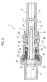
- valve connector With initial reference to Figure 1 , designated as a whole by 1 is a valve connector according to the invention, basically comprising a tubular body 2 provided coaxially at its opposite ends with an inlet fitting 3 and an outlet fitting 4, and a tubular fitting 5.
- the components listed above of the medical connector 1 can all be made of moulded plastic material.
- the tubular fitting 5 has a portion 6 designed to be connected to a first section of a medical line (for example, the tubing connected to a patient undergoing haemodialysis), and a second portion designated by 7, which can be coupled, in the way clarified in what follows, to the inlet fitting 3 of the tubular body 2.
- a medical line for example, the tubing connected to a patient undergoing haemodialysis
- a second portion designated by 7 which can be coupled, in the way clarified in what follows, to the inlet fitting 3 of the tubular body 2.
- the outlet fitting 4 of the tubular body 2 can in turn be connected to a second section of the medical line (for example, to the tubing of a dialyser).
- the portion 7 of the tubular fitting 5 is shaped like a female luer-lock: it has, in a generally conventional way, an internal luer cone 8 and an external end thread 9.
- the inlet fitting 3 of the tubular body 2 is of the male luer-lock type, comprising an external tubular element 10 formed with an internal thread 11 complementary to the thread 9 of the female tubular fitting 5, and an internal tubular element 12.
- Said internal tubular element 12 is mounted axially slidable, with respect to the tubular body 2, between a retracted position, represented in Figure 1 , and an advanced position in the direction of the outlet fitting 4, represented in Figure 2 , passing through the partially advanced position illustrated in Figure 3 .
- the internal tubular element 12 has a portion 13 projecting on the outside of the tubular body 2, through, and for a substantial stretch beyond, the internally threaded element 10 shaped like an external luer cone 14, complementary to the internal luer cone 8 of the female tubular fitting 5.
- Said internal tubular element 12 moreover has an axially internal portion 15 radiused to the axially external portion 13 through an annular flange 16, for example with a polygonal or star shape, coupled in a slidable but non-rotatable way to corresponding internal longitudinal grooves of the body 2 (not visible in the drawings).
- the flange 16 in the retracted position illustrated in Figure 1 rests against an internal annular arrest collar 17 of the tubular body 2, and said position is maintained thanks to the action of a hollow element made of elastic material 18 that is interposed substantially in a fluid-tight way within the tubular body 2, between the inlet fitting 3 and the outlet fitting 4 thereof.
- This element made of elastic material 18 performs substantially three functions: a first function, as has been said, of elastic thrust of the internal tubular element 12 towards the retracted position; a second function of slidable seal of the portion 15 of the tubular element 12; and a third function consisting in defining a valved passage of flow between the inlet fitting 3 and the outlet fitting 4 of the tubular body 2.
- the hollow element made of elastic material 18 has, at one end, an enlarged part 19 blocked between the tubular body and the outlet fitting 4 and formed internally with one or more integral seal rings (not visible) in sliding contact with the external surface of the portion 15 of the internal tubular element 12, and an opposite end 20 resting against the annular flange 16 of the internal tubular element 12.
- An intermediate part 21 of the element 18 has a wall elastically more compliant in an axial direction, conveniently shaped with alternating helical ribbings and grooves, for example, in the way described in detail in the already cited document No. EP-1747796A1 .
- the elastic tubular body 18 has, in a position corresponding to its end facing the outlet fitting 4, a transverse diaphragm 22 formed with a central cut 23 that is normally kept hermetically closed as a result of an appropriate radial pre-loading between the enlarged part 19 and the tubular body 2.
- the free end of the portion 15 of the internal tubular element 12, designated by 24, has a chamfered configuration provided for co-operating, in the way clarified in what follows, with the transverse diaphragm 22 and the corresponding cut 23 of the hollow elastic element 18.
- the external tubular element 10 with the internal thread 11 of the inlet fitting 3 is constituted by a ring nut that is free to turn on the tubular body 2.
- Said rotatable ring nut 10 has a rotatably engaged attachment part 25, for example, following upon an axial snap-action coupling, on an axial appendage 26 of the tubular body 2.
- said rotatable ring nut 10 with the corresponding internal thread 11 and the projecting portion 13 of the internal tubular element 12 formed with the external luer cone 14 are configured in such a way that, when said external luer cone 14 is axially coupled within the internal luer cone 8 of the female fitting 5, screwed engagement between the internal thread 11 of the rotatable ring nut 10 and the external thread 9 of the female fitting 5 is obtained only after engagement by friction between the cones 14 and 8, and following upon an initial axial displacement of the female fitting 5 that produces a consequent axial displacement of the internal tubular element 12 in the direction of the outlet fitting 4, i.e., from the position of closing to the advanced position of opening of the passage of flow through the valve connector 1, compressing the axially more compliant portion 21 of the elastic element 18.
- the arrangement is moreover such that, when the rotatable ring nut 10 is screwed off the female fitting 5 and consequently the internal tubular element 12 returns into the retracted position for closing the passage through the connector 1 as a result of the elastic return of the portion 21 of the body 18, the cones 14 and 8 remain axially coupled to one another by friction and can be separated from one another only following upon a positive action tending to move them away from one another.
- the internal tubular element 12 In the absence of coupling between the female fitting 5 and the tubular body 2, the internal tubular element 12 is kept by the hollow elastic element 18 in the retracted position represented in Figure 1 . In said condition, the end 24 of the internal tubular element 12 is axially retracted with respect to the transverse diaphragm 22 of the hollow elastic element 18 so that the cut 23 remains hermetically closed and the passage of flow between the inlet fitting 3 and the outlet fitting 4 is interrupted.
- the connector 1 sets itself, following upon accidental or in any case undesired unscrewing of the rotatable ring nut 10, in the condition represented in Figure 1 , where retraction of the internal tubular element 12 obtained by the thrust of the hollow elastic element 18 following upon disengagement of the threads 9 and 11 produces closing of the passage of flow as a result of hermetic re-closing of the cut 23 of the diaphragm 22, thus isolating the inlet fitting 3 from the outlet fitting 4.
- the cone 8 of the female fitting 5 remains, however, axially coupled by friction on the cone 14 of the internal tubular element 12 so that the section of the medical line connected to the female fitting 5 is kept closed, in a controlled way, by the valve system of the tubular body 2.
Landscapes
- Health & Medical Sciences (AREA)
- Heart & Thoracic Surgery (AREA)
- Pulmonology (AREA)
- Engineering & Computer Science (AREA)
- Anesthesiology (AREA)
- Biomedical Technology (AREA)
- Hematology (AREA)
- Life Sciences & Earth Sciences (AREA)
- Animal Behavior & Ethology (AREA)
- General Health & Medical Sciences (AREA)
- Public Health (AREA)
- Veterinary Medicine (AREA)
- Infusion, Injection, And Reservoir Apparatuses (AREA)
- External Artificial Organs (AREA)
Applications Claiming Priority (2)
| Application Number | Priority Date | Filing Date | Title |
|---|---|---|---|
| IT000059A ITTO20080059A1 (it) | 2008-01-29 | 2008-01-29 | Connettore valvolare per linee medicali |
| PCT/IB2009/000126 WO2009095760A1 (en) | 2008-01-29 | 2009-01-23 | Valve connector for medical lines |
Publications (2)
| Publication Number | Publication Date |
|---|---|
| EP2237830A1 EP2237830A1 (en) | 2010-10-13 |
| EP2237830B1 true EP2237830B1 (en) | 2012-01-18 |
Family
ID=40290412
Family Applications (1)
| Application Number | Title | Priority Date | Filing Date |
|---|---|---|---|
| EP09706949A Active EP2237830B1 (en) | 2008-01-29 | 2009-01-23 | Valve connector for medical lines |
Country Status (13)
| Country | Link |
|---|---|
| US (1) | US9889287B2 (it) |
| EP (1) | EP2237830B1 (it) |
| JP (1) | JP5481392B2 (it) |
| CN (1) | CN101980746B (it) |
| AT (1) | ATE541610T1 (it) |
| AU (1) | AU2009208763B2 (it) |
| CA (1) | CA2713410C (it) |
| ES (1) | ES2381070T3 (it) |
| IT (1) | ITTO20080059A1 (it) |
| NZ (1) | NZ587047A (it) |
| PT (1) | PT2237830E (it) |
| WO (1) | WO2009095760A1 (it) |
| ZA (1) | ZA201005542B (it) |
Families Citing this family (40)
| Publication number | Priority date | Publication date | Assignee | Title |
|---|---|---|---|---|
| US6695817B1 (en) | 2000-07-11 | 2004-02-24 | Icu Medical, Inc. | Medical valve with positive flow characteristics |
| HK1077154A2 (en) | 2003-12-30 | 2006-02-03 | Icu Medical, Inc. | Valve assembly |
| US20060161115A1 (en) | 2004-11-05 | 2006-07-20 | Fangrow Thomas F | Soft-grip medical connector |
| US20070088292A1 (en) | 2005-07-06 | 2007-04-19 | Fangrow Thomas F Jr | Medical connector with closeable male luer |
| US9168366B2 (en) | 2008-12-19 | 2015-10-27 | Icu Medical, Inc. | Medical connector with closeable luer connector |
| US8454579B2 (en) | 2009-03-25 | 2013-06-04 | Icu Medical, Inc. | Medical connector with automatic valves and volume regulator |
| USD644731S1 (en) | 2010-03-23 | 2011-09-06 | Icu Medical, Inc. | Medical connector |
| US8758306B2 (en) | 2010-05-17 | 2014-06-24 | Icu Medical, Inc. | Medical connectors and methods of use |
| JP5893286B2 (ja) * | 2011-08-05 | 2016-03-23 | 日機装株式会社 | ロック式接続具 |
| US8777931B2 (en) | 2011-08-19 | 2014-07-15 | Alcon Research, Ltd. | Retractable luer lock fittings |
| AU2012304344B2 (en) | 2011-09-09 | 2016-02-04 | Icu Medical, Inc. | Medical connectors with fluid-resistant mating interfaces |
| DE102012005187B4 (de) * | 2012-03-16 | 2023-03-30 | Fresenius Medical Care Deutschland Gmbh | Medizinische Vorrichtung mit einer Buchsen-Einheit zum Anschluss einer Vorrichtung zur Bereitstellung von medizinischen Flüssigkeiten |
| EP2756863B1 (en) * | 2013-01-22 | 2020-05-13 | Micrel Medical Devices S.A. | Lock connection device for medical fluid lines |
| JP2014210067A (ja) * | 2013-04-19 | 2014-11-13 | 東レ・メディカル株式会社 | 分岐ポート |
| EP3079739B1 (en) | 2013-12-11 | 2023-02-22 | ICU Medical, Inc. | Check valve |
| WO2016057981A1 (en) | 2014-10-10 | 2016-04-14 | Nxstage Medical, Inc. | Pinch clamp devices, methods, and systems |
| USD793551S1 (en) | 2014-12-03 | 2017-08-01 | Icu Medical, Inc. | Fluid manifold |
| USD786427S1 (en) | 2014-12-03 | 2017-05-09 | Icu Medical, Inc. | Fluid manifold |
| MX368388B (es) * | 2015-01-21 | 2019-10-01 | Borla Ind | Conectador de luer macho con valvula. |
| ITUA20163611A1 (it) * | 2016-05-19 | 2017-11-19 | Borla Ind | Connettore valvolare per linee medicali |
| IT201600075597A1 (it) * | 2016-07-19 | 2018-01-19 | Borla Ind | Componente di flusso particolarmente per linee medicali per emodialisi |
| JP6962923B2 (ja) * | 2016-09-26 | 2021-11-05 | テルモ株式会社 | オスコネクタ、医療器具及び接続方法 |
| JP6995837B2 (ja) * | 2017-03-24 | 2022-01-17 | テルモ株式会社 | 医療器具 |
| US11344715B2 (en) | 2018-01-26 | 2022-05-31 | Becton, Dickinson And Company | Flush syringe with disinfecting feature |
| US11083847B2 (en) | 2018-01-26 | 2021-08-10 | Becton, Dickinson And Company | Flush syringe with flip cap |
| US10871246B2 (en) | 2018-01-30 | 2020-12-22 | Becton, Dickinson And Company | Universal connector or cap for male and female threaded fittings |
| US11273298B2 (en) * | 2018-04-10 | 2022-03-15 | Becton, Dickinson And Company | Universal single-use cap for male and female connectors |
| EP3866905A1 (en) * | 2018-10-19 | 2021-08-25 | Fresenius Kabi Deutschland GmbH | Connector assembly for connecting medical lines |
| US11511100B2 (en) | 2019-01-30 | 2022-11-29 | Becton, Dickinson And Company | Universal cap for male and female connectors |
| CN114269422B (zh) | 2019-08-08 | 2024-12-27 | 贝克顿·迪金森公司 | 具有压力密封件的通用帽 |
| US12544550B2 (en) | 2019-08-09 | 2026-02-10 | Becton, Dickinson And Company | Disinfecting cap with pressure seal capability |
| US11975168B2 (en) | 2019-11-18 | 2024-05-07 | Becton, Dickinson And Company | Disinfectant cap |
| US11890445B2 (en) | 2019-12-23 | 2024-02-06 | Becton, Dickinson And Company | Universal disinfection cap |
| US12029828B2 (en) | 2020-03-05 | 2024-07-09 | Becton, Dickinson And Company | Disinfection cap |
| US12005223B2 (en) | 2020-04-17 | 2024-06-11 | Becton, Dickinson And Company | Disinfection cap |
| US11890446B2 (en) | 2020-04-17 | 2024-02-06 | Becton, Dickinson And Company | Cap for male and female threaded fittings |
| US11969572B2 (en) | 2020-04-17 | 2024-04-30 | Becton, Dickinson And Company | Disinfection cap |
| US12383719B2 (en) | 2020-04-17 | 2025-08-12 | Becton, Dickinson And Company | Disinfecting cap with re-use prevention |
| US11389637B2 (en) * | 2021-06-30 | 2022-07-19 | Human Hydrology Devices | Systems and methods for directing fluid flow |
| USD1105422S1 (en) | 2024-02-09 | 2025-12-09 | Icu Medical, Inc. | Medical connector cover |
Family Cites Families (26)
| Publication number | Priority date | Publication date | Assignee | Title |
|---|---|---|---|---|
| DE2817102C2 (de) | 1978-04-19 | 1985-01-24 | Dr. Eduard Fresenius, Chemisch-pharmazeutische Industrie KG, 6380 Bad Homburg | Anschlußstück für Kunststoffkanülen oder Venenkatheter |
| DK0988871T3 (da) | 1991-12-18 | 2004-05-24 | Icu Medical Inc | Fremgangsmåde til overføring af fluid |
| US5699821A (en) | 1993-10-13 | 1997-12-23 | Paradis; Joseph R. | Control of fluid flow |
| JP3456241B2 (ja) | 1993-11-26 | 2003-10-14 | 株式会社ジェイ・エム・エス | ロック型接続具 |
| US5439451A (en) | 1994-03-22 | 1995-08-08 | B. Braun Medical, Inc. | Capless medical backcheck valve |
| US6183448B1 (en) | 1994-06-20 | 2001-02-06 | Bruno Franz P. Mayer | Needleless injection site |
| NZ286445A (en) | 1995-05-16 | 1997-12-19 | Ivac Corp | Needleless luer connector: deformable piston occludes bore |
| US5700248A (en) | 1995-12-15 | 1997-12-23 | Icu Medical, Inc. | Medical valve with tire seal |
| US6079432A (en) | 1996-07-02 | 2000-06-27 | Paradis; Joseph R. | Control of fluid flow by oval shaped valve member containing a cam interface |
| US6050978A (en) | 1997-05-09 | 2000-04-18 | Becton Dickinson And Company | Needleless valve connector |
| US6089541A (en) | 1998-09-10 | 2000-07-18 | Halkey-Roberts Corporation | Valve having a valve body and a deformable stem therein |
| US6299132B1 (en) * | 1999-03-31 | 2001-10-09 | Halkey-Roberts Corporation | Reflux valve |
| US6706022B1 (en) | 1999-07-27 | 2004-03-16 | Alaris Medical Systems, Inc. | Needleless medical connector with expandable valve mechanism |
| WO2002034326A2 (en) | 2000-10-23 | 2002-05-02 | Nypro, Inc. | Anti-drawback medical valve |
| US6543745B1 (en) | 2001-10-09 | 2003-04-08 | Halkey-Roberts Corporation | Male luer valve |
| US7914502B2 (en) | 2003-07-31 | 2011-03-29 | Nypro Inc. | Anti-drawback medical valve |
| US7470254B2 (en) | 2003-08-18 | 2008-12-30 | Medical Components, Inc. | Needle with sealing valve |
| US20050090805A1 (en) | 2003-10-28 | 2005-04-28 | Shaw Scott R. | Reconnectable disconnect device for fluid transfer line |
| ITTO20040524A1 (it) | 2004-07-27 | 2004-10-27 | Borla Ind | Connettore valvolareper linee medicali di infusione |
| US7306566B2 (en) | 2004-09-15 | 2007-12-11 | Cardinal Health 303, Inc. | Needle free blood collection device with male connector valve |
| US7296782B2 (en) | 2004-10-01 | 2007-11-20 | Halkey-Roberts Corporation | Dome check valve |
| US7645274B2 (en) * | 2004-12-10 | 2010-01-12 | Cardinal Health 303, Inc. | Self-sealing male luer connector with multiple seats |
| ITTO20050515A1 (it) * | 2005-07-25 | 2007-01-26 | Borla Ind | Connettore valvolare medicale |
| JP4878496B2 (ja) * | 2005-12-28 | 2012-02-15 | 日本コヴィディエン株式会社 | 雄ルアーコネクター |
| ITTO20060206A1 (it) | 2006-03-17 | 2007-09-18 | Borla Ind | Connettore valvolare per linee medicali |
| JP5161457B2 (ja) * | 2006-04-03 | 2013-03-13 | 日本コヴィディエン株式会社 | 雄ルアーコネクター |
-
2008
- 2008-01-29 IT IT000059A patent/ITTO20080059A1/it unknown
-
2009
- 2009-01-23 AU AU2009208763A patent/AU2009208763B2/en active Active
- 2009-01-23 AT AT09706949T patent/ATE541610T1/de active
- 2009-01-23 EP EP09706949A patent/EP2237830B1/en active Active
- 2009-01-23 PT PT09706949T patent/PT2237830E/pt unknown
- 2009-01-23 US US12/865,224 patent/US9889287B2/en active Active
- 2009-01-23 CN CN2009801114651A patent/CN101980746B/zh active Active
- 2009-01-23 JP JP2010544804A patent/JP5481392B2/ja active Active
- 2009-01-23 NZ NZ587047A patent/NZ587047A/en unknown
- 2009-01-23 WO PCT/IB2009/000126 patent/WO2009095760A1/en not_active Ceased
- 2009-01-23 ES ES09706949T patent/ES2381070T3/es active Active
- 2009-01-23 CA CA2713410A patent/CA2713410C/en active Active
-
2010
- 2010-08-03 ZA ZA2010/05542A patent/ZA201005542B/en unknown
Also Published As
| Publication number | Publication date |
|---|---|
| AU2009208763A1 (en) | 2009-08-06 |
| US9889287B2 (en) | 2018-02-13 |
| US20110060293A1 (en) | 2011-03-10 |
| CN101980746B (zh) | 2013-05-22 |
| JP5481392B2 (ja) | 2014-04-23 |
| WO2009095760A1 (en) | 2009-08-06 |
| CN101980746A (zh) | 2011-02-23 |
| CA2713410A1 (en) | 2009-08-06 |
| ES2381070T3 (es) | 2012-05-22 |
| ITTO20080059A1 (it) | 2009-07-30 |
| ZA201005542B (en) | 2011-04-28 |
| ATE541610T1 (de) | 2012-02-15 |
| JP2011510728A (ja) | 2011-04-07 |
| AU2009208763B2 (en) | 2014-01-30 |
| NZ587047A (en) | 2012-03-30 |
| CA2713410C (en) | 2015-11-24 |
| PT2237830E (pt) | 2012-03-05 |
| EP2237830A1 (en) | 2010-10-13 |
Similar Documents
| Publication | Publication Date | Title |
|---|---|---|
| EP2237830B1 (en) | Valve connector for medical lines | |
| US10537726B2 (en) | Tubular fitting for medical fluid lines | |
| EP3099374B1 (en) | Valved connector for medical lines | |
| US7666170B2 (en) | Medical valve connector | |
| EP3047872B1 (en) | Valved male luer connector | |
| EP3458145B1 (en) | Valved connector for medical lines | |
| NZ747353B2 (en) | Valved connector for medical lines | |
| NZ716190B2 (en) | Valved male luer connector |
Legal Events
| Date | Code | Title | Description |
|---|---|---|---|
| PUAI | Public reference made under article 153(3) epc to a published international application that has entered the european phase |
Free format text: ORIGINAL CODE: 0009012 |
|
| 17P | Request for examination filed |
Effective date: 20100729 |
|
| AK | Designated contracting states |
Kind code of ref document: A1 Designated state(s): AT BE BG CH CY CZ DE DK EE ES FI FR GB GR HR HU IE IS IT LI LT LU LV MC MK MT NL NO PL PT RO SE SI SK TR |
|
| AX | Request for extension of the european patent |
Extension state: AL BA RS |
|
| DAX | Request for extension of the european patent (deleted) | ||
| GRAP | Despatch of communication of intention to grant a patent |
Free format text: ORIGINAL CODE: EPIDOSNIGR1 |
|
| GRAC | Information related to communication of intention to grant a patent modified |
Free format text: ORIGINAL CODE: EPIDOSCIGR1 |
|
| GRAS | Grant fee paid |
Free format text: ORIGINAL CODE: EPIDOSNIGR3 |
|
| GRAA | (expected) grant |
Free format text: ORIGINAL CODE: 0009210 |
|
| AK | Designated contracting states |
Kind code of ref document: B1 Designated state(s): AT BE BG CH CY CZ DE DK EE ES FI FR GB GR HR HU IE IS IT LI LT LU LV MC MK MT NL NO PL PT RO SE SI SK TR |
|
| REG | Reference to a national code |
Ref country code: GB Ref legal event code: FG4D |
|
| REG | Reference to a national code |
Ref country code: CH Ref legal event code: EP |
|
| REG | Reference to a national code |
Ref country code: AT Ref legal event code: REF Ref document number: 541610 Country of ref document: AT Kind code of ref document: T Effective date: 20120215 Ref country code: IE Ref legal event code: FG4D |
|
| REG | Reference to a national code |
Ref country code: PT Ref legal event code: SC4A Free format text: AVAILABILITY OF NATIONAL TRANSLATION Effective date: 20120222 |
|
| REG | Reference to a national code |
Ref country code: DE Ref legal event code: R096 Ref document number: 602009004755 Country of ref document: DE Effective date: 20120315 |
|
| REG | Reference to a national code |
Ref country code: SE Ref legal event code: TRGR |
|
| REG | Reference to a national code |
Ref country code: NL Ref legal event code: T3 |
|
| REG | Reference to a national code |
Ref country code: ES Ref legal event code: FG2A Ref document number: 2381070 Country of ref document: ES Kind code of ref document: T3 Effective date: 20120522 |
|
| LTIE | Lt: invalidation of european patent or patent extension |
Effective date: 20120118 |
|
| PG25 | Lapsed in a contracting state [announced via postgrant information from national office to epo] |
Ref country code: LT Free format text: LAPSE BECAUSE OF FAILURE TO SUBMIT A TRANSLATION OF THE DESCRIPTION OR TO PAY THE FEE WITHIN THE PRESCRIBED TIME-LIMIT Effective date: 20120118 Ref country code: NO Free format text: LAPSE BECAUSE OF FAILURE TO SUBMIT A TRANSLATION OF THE DESCRIPTION OR TO PAY THE FEE WITHIN THE PRESCRIBED TIME-LIMIT Effective date: 20120418 Ref country code: IS Free format text: LAPSE BECAUSE OF FAILURE TO SUBMIT A TRANSLATION OF THE DESCRIPTION OR TO PAY THE FEE WITHIN THE PRESCRIBED TIME-LIMIT Effective date: 20120518 Ref country code: BG Free format text: LAPSE BECAUSE OF FAILURE TO SUBMIT A TRANSLATION OF THE DESCRIPTION OR TO PAY THE FEE WITHIN THE PRESCRIBED TIME-LIMIT Effective date: 20120418 Ref country code: HR Free format text: LAPSE BECAUSE OF FAILURE TO SUBMIT A TRANSLATION OF THE DESCRIPTION OR TO PAY THE FEE WITHIN THE PRESCRIBED TIME-LIMIT Effective date: 20120118 |
|
| PG25 | Lapsed in a contracting state [announced via postgrant information from national office to epo] |
Ref country code: GR Free format text: LAPSE BECAUSE OF FAILURE TO SUBMIT A TRANSLATION OF THE DESCRIPTION OR TO PAY THE FEE WITHIN THE PRESCRIBED TIME-LIMIT Effective date: 20120419 Ref country code: LV Free format text: LAPSE BECAUSE OF FAILURE TO SUBMIT A TRANSLATION OF THE DESCRIPTION OR TO PAY THE FEE WITHIN THE PRESCRIBED TIME-LIMIT Effective date: 20120118 Ref country code: FI Free format text: LAPSE BECAUSE OF FAILURE TO SUBMIT A TRANSLATION OF THE DESCRIPTION OR TO PAY THE FEE WITHIN THE PRESCRIBED TIME-LIMIT Effective date: 20120118 Ref country code: PL Free format text: LAPSE BECAUSE OF FAILURE TO SUBMIT A TRANSLATION OF THE DESCRIPTION OR TO PAY THE FEE WITHIN THE PRESCRIBED TIME-LIMIT Effective date: 20120118 |
|
| REG | Reference to a national code |
Ref country code: AT Ref legal event code: MK05 Ref document number: 541610 Country of ref document: AT Kind code of ref document: T Effective date: 20120118 |
|
| PG25 | Lapsed in a contracting state [announced via postgrant information from national office to epo] |
Ref country code: CY Free format text: LAPSE BECAUSE OF FAILURE TO SUBMIT A TRANSLATION OF THE DESCRIPTION OR TO PAY THE FEE WITHIN THE PRESCRIBED TIME-LIMIT Effective date: 20120118 |
|
| PG25 | Lapsed in a contracting state [announced via postgrant information from national office to epo] |
Ref country code: RO Free format text: LAPSE BECAUSE OF FAILURE TO SUBMIT A TRANSLATION OF THE DESCRIPTION OR TO PAY THE FEE WITHIN THE PRESCRIBED TIME-LIMIT Effective date: 20120118 Ref country code: EE Free format text: LAPSE BECAUSE OF FAILURE TO SUBMIT A TRANSLATION OF THE DESCRIPTION OR TO PAY THE FEE WITHIN THE PRESCRIBED TIME-LIMIT Effective date: 20120118 Ref country code: CZ Free format text: LAPSE BECAUSE OF FAILURE TO SUBMIT A TRANSLATION OF THE DESCRIPTION OR TO PAY THE FEE WITHIN THE PRESCRIBED TIME-LIMIT Effective date: 20120118 Ref country code: DK Free format text: LAPSE BECAUSE OF FAILURE TO SUBMIT A TRANSLATION OF THE DESCRIPTION OR TO PAY THE FEE WITHIN THE PRESCRIBED TIME-LIMIT Effective date: 20120118 Ref country code: SI Free format text: LAPSE BECAUSE OF FAILURE TO SUBMIT A TRANSLATION OF THE DESCRIPTION OR TO PAY THE FEE WITHIN THE PRESCRIBED TIME-LIMIT Effective date: 20120118 |
|
| PLBE | No opposition filed within time limit |
Free format text: ORIGINAL CODE: 0009261 |
|
| STAA | Information on the status of an ep patent application or granted ep patent |
Free format text: STATUS: NO OPPOSITION FILED WITHIN TIME LIMIT |
|
| PG25 | Lapsed in a contracting state [announced via postgrant information from national office to epo] |
Ref country code: SK Free format text: LAPSE BECAUSE OF FAILURE TO SUBMIT A TRANSLATION OF THE DESCRIPTION OR TO PAY THE FEE WITHIN THE PRESCRIBED TIME-LIMIT Effective date: 20120118 |
|
| 26N | No opposition filed |
Effective date: 20121019 |
|
| PG25 | Lapsed in a contracting state [announced via postgrant information from national office to epo] |
Ref country code: AT Free format text: LAPSE BECAUSE OF FAILURE TO SUBMIT A TRANSLATION OF THE DESCRIPTION OR TO PAY THE FEE WITHIN THE PRESCRIBED TIME-LIMIT Effective date: 20120118 |
|
| REG | Reference to a national code |
Ref country code: DE Ref legal event code: R097 Ref document number: 602009004755 Country of ref document: DE Effective date: 20121019 |
|
| PG25 | Lapsed in a contracting state [announced via postgrant information from national office to epo] |
Ref country code: MK Free format text: LAPSE BECAUSE OF FAILURE TO SUBMIT A TRANSLATION OF THE DESCRIPTION OR TO PAY THE FEE WITHIN THE PRESCRIBED TIME-LIMIT Effective date: 20120118 |
|
| PG25 | Lapsed in a contracting state [announced via postgrant information from national office to epo] |
Ref country code: MT Free format text: LAPSE BECAUSE OF FAILURE TO SUBMIT A TRANSLATION OF THE DESCRIPTION OR TO PAY THE FEE WITHIN THE PRESCRIBED TIME-LIMIT Effective date: 20120118 |
|
| REG | Reference to a national code |
Ref country code: CH Ref legal event code: PL |
|
| PG25 | Lapsed in a contracting state [announced via postgrant information from national office to epo] |
Ref country code: CH Free format text: LAPSE BECAUSE OF NON-PAYMENT OF DUE FEES Effective date: 20130131 Ref country code: LI Free format text: LAPSE BECAUSE OF NON-PAYMENT OF DUE FEES Effective date: 20130131 |
|
| PG25 | Lapsed in a contracting state [announced via postgrant information from national office to epo] |
Ref country code: TR Free format text: LAPSE BECAUSE OF FAILURE TO SUBMIT A TRANSLATION OF THE DESCRIPTION OR TO PAY THE FEE WITHIN THE PRESCRIBED TIME-LIMIT Effective date: 20120118 |
|
| PG25 | Lapsed in a contracting state [announced via postgrant information from national office to epo] |
Ref country code: LU Free format text: LAPSE BECAUSE OF NON-PAYMENT OF DUE FEES Effective date: 20120123 |
|
| PG25 | Lapsed in a contracting state [announced via postgrant information from national office to epo] |
Ref country code: HU Free format text: LAPSE BECAUSE OF FAILURE TO SUBMIT A TRANSLATION OF THE DESCRIPTION OR TO PAY THE FEE WITHIN THE PRESCRIBED TIME-LIMIT Effective date: 20090123 |
|
| REG | Reference to a national code |
Ref country code: FR Ref legal event code: PLFP Year of fee payment: 8 |
|
| REG | Reference to a national code |
Ref country code: FR Ref legal event code: PLFP Year of fee payment: 9 |
|
| REG | Reference to a national code |
Ref country code: FR Ref legal event code: PLFP Year of fee payment: 10 |
|
| P01 | Opt-out of the competence of the unified patent court (upc) registered |
Effective date: 20230614 |
|
| PGFP | Annual fee paid to national office [announced via postgrant information from national office to epo] |
Ref country code: NL Payment date: 20260122 Year of fee payment: 18 |
|
| PGFP | Annual fee paid to national office [announced via postgrant information from national office to epo] |
Ref country code: SE Payment date: 20260126 Year of fee payment: 18 |
|
| PGFP | Annual fee paid to national office [announced via postgrant information from national office to epo] |
Ref country code: GB Payment date: 20260126 Year of fee payment: 18 |
|
| PGFP | Annual fee paid to national office [announced via postgrant information from national office to epo] |
Ref country code: ES Payment date: 20260210 Year of fee payment: 18 Ref country code: MC Payment date: 20260120 Year of fee payment: 18 |
|
| PGFP | Annual fee paid to national office [announced via postgrant information from national office to epo] |
Ref country code: DE Payment date: 20260127 Year of fee payment: 18 Ref country code: IE Payment date: 20260120 Year of fee payment: 18 |
|
| PGFP | Annual fee paid to national office [announced via postgrant information from national office to epo] |
Ref country code: IT Payment date: 20260115 Year of fee payment: 18 Ref country code: BE Payment date: 20260123 Year of fee payment: 18 |
|
| PGFP | Annual fee paid to national office [announced via postgrant information from national office to epo] |
Ref country code: FR Payment date: 20260126 Year of fee payment: 18 |
|
| PGFP | Annual fee paid to national office [announced via postgrant information from national office to epo] |
Ref country code: PT Payment date: 20260106 Year of fee payment: 18 |