EP2237405B1 - Dispositif de commande pour le changement de la modalité de commande d'une charge électromagnétique - Google Patents
Dispositif de commande pour le changement de la modalité de commande d'une charge électromagnétique Download PDFInfo
- Publication number
- EP2237405B1 EP2237405B1 EP10158288A EP10158288A EP2237405B1 EP 2237405 B1 EP2237405 B1 EP 2237405B1 EP 10158288 A EP10158288 A EP 10158288A EP 10158288 A EP10158288 A EP 10158288A EP 2237405 B1 EP2237405 B1 EP 2237405B1
- Authority
- EP
- European Patent Office
- Prior art keywords
- modality
- signal
- tri
- load
- current
- Prior art date
- Legal status (The legal status is an assumption and is not a legal conclusion. Google has not performed a legal analysis and makes no representation as to the accuracy of the status listed.)
- Active
Links
- 230000008859 change Effects 0.000 title claims description 44
- 238000000034 method Methods 0.000 claims description 6
- 230000004044 response Effects 0.000 claims description 4
- 238000001514 detection method Methods 0.000 claims 2
- 230000007704 transition Effects 0.000 description 14
- 238000010586 diagram Methods 0.000 description 13
- 230000001360 synchronised effect Effects 0.000 description 7
- 230000003134 recirculating effect Effects 0.000 description 5
- 230000008901 benefit Effects 0.000 description 2
- 230000003247 decreasing effect Effects 0.000 description 1
- 230000003111 delayed effect Effects 0.000 description 1
- 230000009467 reduction Effects 0.000 description 1
Images


Classifications
-
- H—ELECTRICITY
- H02—GENERATION; CONVERSION OR DISTRIBUTION OF ELECTRIC POWER
- H02P—CONTROL OR REGULATION OF ELECTRIC MOTORS, ELECTRIC GENERATORS OR DYNAMO-ELECTRIC CONVERTERS; CONTROLLING TRANSFORMERS, REACTORS OR CHOKE COILS
- H02P25/00—Arrangements or methods for the control of AC motors characterised by the kind of AC motor or by structural details
- H02P25/02—Arrangements or methods for the control of AC motors characterised by the kind of AC motor or by structural details characterised by the kind of motor
- H02P25/032—Reciprocating, oscillating or vibrating motors
- H02P25/034—Voice coil motors
-
- G—PHYSICS
- G11—INFORMATION STORAGE
- G11B—INFORMATION STORAGE BASED ON RELATIVE MOVEMENT BETWEEN RECORD CARRIER AND TRANSDUCER
- G11B5/00—Recording by magnetisation or demagnetisation of a record carrier; Reproducing by magnetic means; Record carriers therefor
- G11B5/02—Recording, reproducing, or erasing methods; Read, write or erase circuits therefor
- G11B5/022—H-Bridge head driver circuit, the "H" configuration allowing to inverse the current direction in the head
-
- G—PHYSICS
- G11—INFORMATION STORAGE
- G11B—INFORMATION STORAGE BASED ON RELATIVE MOVEMENT BETWEEN RECORD CARRIER AND TRANSDUCER
- G11B5/00—Recording by magnetisation or demagnetisation of a record carrier; Reproducing by magnetic means; Record carriers therefor
- G11B5/48—Disposition or mounting of heads or head supports relative to record carriers ; arrangements of heads, e.g. for scanning the record carrier to increase the relative speed
- G11B5/54—Disposition or mounting of heads or head supports relative to record carriers ; arrangements of heads, e.g. for scanning the record carrier to increase the relative speed with provision for moving the head into or out of its operative position or across tracks
- G11B5/55—Track change, selection or acquisition by displacement of the head
- G11B5/5521—Track change, selection or acquisition by displacement of the head across disk tracks
- G11B5/5526—Control therefor; circuits, track configurations or relative disposition of servo-information transducers and servo-information tracks for control thereof
- G11B5/553—Details
- G11B5/5547—"Seek" control and circuits therefor
-
- H—ELECTRICITY
- H02—GENERATION; CONVERSION OR DISTRIBUTION OF ELECTRIC POWER
- H02P—CONTROL OR REGULATION OF ELECTRIC MOTORS, ELECTRIC GENERATORS OR DYNAMO-ELECTRIC CONVERTERS; CONTROLLING TRANSFORMERS, REACTORS OR CHOKE COILS
- H02P6/00—Arrangements for controlling synchronous motors or other dynamo-electric motors using electronic commutation dependent on the rotor position; Electronic commutators therefor
- H02P6/08—Arrangements for controlling the speed or torque of a single motor
- H02P6/085—Arrangements for controlling the speed or torque of a single motor in a bridge configuration
-
- H—ELECTRICITY
- H02—GENERATION; CONVERSION OR DISTRIBUTION OF ELECTRIC POWER
- H02P—CONTROL OR REGULATION OF ELECTRIC MOTORS, ELECTRIC GENERATORS OR DYNAMO-ELECTRIC CONVERTERS; CONTROLLING TRANSFORMERS, REACTORS OR CHOKE COILS
- H02P6/00—Arrangements for controlling synchronous motors or other dynamo-electric motors using electronic commutation dependent on the rotor position; Electronic commutators therefor
- H02P6/20—Arrangements for starting
- H02P6/22—Arrangements for starting in a selected direction of rotation
Definitions
- the present invention relates to a control device for the change of the driving modality of an electromagnetic load, particularly a voice coil motor used in applications for computer hard disks.
- the linear modality current control of a voice coil motor in hard disk applications is accomplished by means of a power stage in a bridge configuration operating in class AB for the known properties of good linearity and crossing distortion.
- FIG. 1 shows the diagram of a power stage 1 with driving circuits 2 and voice coil motor 3 as described in the aforementioned patent.
- Power stage 1 comprises two half-bridges of transistors M1-M2 and M3-M4 arranged between voltage VM and mass GND and controlled by driving circuits 2; the voice coil motor is coupled between the shared terminal of said transistor bridges and is therefore driven through the outputs VCM_+ and VCM_-.
- Each driving circuit 2 is adapted to drive the corresponding output VCM_+ and VCM_- by means of a pulse width-modulated signal obtained by means of comparators adapted to compare the two 180° phase-shifted triangular voltages Tri and Tri180, produced by means of appropriate oscillators, for example, with a signal Eout.
- Said signal Eout is produced by an error amplifier 4 having a signal Vref on the non-inverting input terminal and a signal existing on the inverting input terminal and corresponding to the difference between the current Ivcm flowing on the voice coil motor 3, detected by a resistance Rs and an appropriate amplifier Gs, and an external signal Dout.
- the signal Dout corresponds to the desired current value on the outputs VCM_+ and VCM_-.
- the signal Eout corresponds to the difference between the detected current and the signal Dout.
- the peculiarity of this system is that the current in the load is controlled by varying the duty cycle of the two outputs VCM_+ and VCM_-of stage power 1; the null current condition is obtained by driving the two outputs with two signals having the same frequency and 50%.duty cycle.
- the result is that the current will pass through the load with direction and intensity depending on the difference in duty cycle between the two outputs.
- Figure 2 shows the timing diagrams of the signals Tri, Tri180, Eout, VCM_+, VCM_-, Ivcm and the pulse signals Tri-Peak and Tri-Mid which show the (positive and negative) voltage peak Tri and the crossing point between the voltages Tri180 and Tri, respectively; said signals describe the operation of the current control in case of positive current in accordance with the apparatus in figure 1 .
- This method allows to obtain a reduction of the power dissipated by the power stage by means of the change of operation modality of the power stage from linear to PWM which occurs by means of an external signal L/P sent to the driving circuits 2.
- the voice coil motor 3 is controlled so that the reading and writing head moved by the same follows a track and allows to read and/or write data on the disk ("tracking mode"), the current required for this operation is of a low value, and power stage 1 is therefore controlled in linear modality.
- the reading and writing head moved by the voice coil motor 3 should operate a track skip to read new data ("seeking mode"), the current required to rapidly accelerate and brake is of a far higher level than in the case of the tracking mode. Therefore, in order to increase the efficiency of the system and decrease the power dissipated by the output stage, during the track skip or seeking the voice coil motor 3 is controlled in PWM modality to then return to linear modality at the end of the decelerating step, where the heads reach the track to be read and the current to be controlled is of a low value.
- FIG 3 there is depicted a typical profile of the current Ivcm in the voice coil motor 3 during a seeking operation in accordance with the known art: the current to be controlled is of a high value in order to rapidly accelerate and decelerate, and the current control operates in PWM modality in order to decrease the power dissipated by the output stage.
- both the speed of the motor and the current controlled therein are of a low value, whereby the operation modality is changed into linear modality LIN by means of the signal L/P.
- Figure 4 shows the voltages VCM_+, VCM_-, the current Ivcm and the signal Eout during the transition from the current control in pulse width modality (PWM) to the control in linear modality LIN in the control apparatus in Figure 1 .
- PWM pulse width modality
- the current Ivcm in the voice coil motor 3 has a hole or glitch due to the adjustment time needed by the control apparatus during the transition from the modality PWM to the linear modality LIN.
- Figure 5 shows the signals in figure 4 in more detail.
- the mean value of the controlled current is the same.
- the current Ivcm is characterized by a ripple which is a function of the frequency of signal PWM, and by the features of inductance and resistance of the voice coil motor 3.
- the modality change from PWM to LIN takes place asynchronously as compared to the PWM frequency which the power stage 1 is operating at, therefore it may happen at any time during the period of the ripple of the current Icvm in the voice coil motor 3.
- the change of the operation modality takes place exactly at the end of a recirculating step, where the current is at its minimum value.
- This current glitch is a discontinuity existing in the power-assisted control system which places the heads on the disk tracks and which is moved by the voice coil motor 3, and may deteriorate the system performance in terms of accuracy and arrival time on the tracks.
- US 2005/264920 discloses a dual-mode positioning driver for a voice coil motor in a disk drive system; the dual-mode comprising the PWM operation modality and the linear operation modality.
- the system comprising a control signal to change the operation modality of an electromagnetic load; said control signal is synchronized.
- the synchronization signal is determined by comparing, by means of two comparator 56h and 561, the output voltages VCMP and VCMN with a reference signal VM/2.
- the object of the present invention is to provide a control device for the change of the driving modality of an electromagnetic load which minimizes the time required to change said driving modality and, specifically, limits the variation of the mean value of the current in the voice coil motor during the change of the driving modality, if the electromagnetic load is a voice coil motor.
- a control apparatus may be provided as defined in claim 12.
- Figure 6 shows a control device for the change of driving modality of an electromagnetic load in accordance with the first embodiment of the present invention. Particularly Figure 6 shows a device to synchronize the change of driving modality of an electromagnetic load.
- Said device has at the input a control signal L/P to change the operation modality of an electromagnetic load 3 passed through by a current Ivcm from a first operation modality to a second operation modality or vice versa, and a signal Tri_Peak, Tri_Mid representative of the passage of the current Ivcm passing through the load 3 for substantially its mean value IM.
- Said device comprises means 100 adapted to synchronize said control signal L/P for changing from the first operation modality to the second operation modality or vice versa of the electromagnetic load with said signal representative of the passage of the current Ivcm passing through the load 3 for substantially its mean value IM.
- the device is adapted to generate a control signal Slp as a function of said synchronization.
- the first operation modality is the pulse width modulation (PWM) modality.
- PWM pulse width modulation
- the synchronization takes place with the passage of the current Ivcm for the mean value IM of the current passing through the electromagnetic load so that, if the electromagnetic load is the voice coil motor 3 in Figure 1 and the driving apparatus is that in Figure 1 , said passage of the current Ivcm for the mean value IM coincides with the either positive or negative peak, or the mean value of the triangular voltage used to generate the PWM signals VCM_+ and VCM_-; therefore, we have either the signal Tri_Peak or the signal Tri_Mid at the input of the device 100.
- the device in accordance with the invention may thus be specifically applied to the apparatus for controlling a voice coil motor 3 as that in Figure 1 , already described and known from patent EP 760552 , thus obtaining the control apparatus in Figure 7 ; in such a case, the device 100 allows the synchronization to change the operation modality from PWM to linear LIN.
- the device 100 has at the input the control to change the modality L/P and the signal Tri_Peak or the signal Tri_Mid, i.e.
- the Tri_Peak and Tri_Mid signals are detected by suitable means 300 and 301 internal to the driving circuits 2 or external thereto but still belonging to the control apparatus and already known.
- the output of the device 100 is a signal Slp which synchronizes the signal L/P with the peak or the mean value of the triangular waveform Tri or Tri180. Therefore, there is a synchronization with the frequency of the PWM voltage at which the power stage 1 is operating. Even more specifically, means 301 detect the signal Tri_Mid at every crossing of the triangular waveforms Tri and Tri180.
- the current Ivcm presents a ripple overlapping the mean value: the current Ivcm of the voice coil motor 3 crosses the mean value IM halfway through the conducting step, when the two outputs VCM_+ and VCM_- have a different potential, and halfway through the recirculating step, when the two outputs VCM_+ and YCM_-have an equal (low or high) potential.
- the change of modality from PWM to linear LIN may be synchronously synchronized with the PWM frequency at which the power stage 1 is operating.
- the device 100 is implemented with a flip-flop.
- the asynchronous control L/P defining the operation modality is sent to the input D of the flip-flop; the clock Ck of this flip-flop is represented by the output signal from an OR gate 101 having at the input the two signals Tri_Peak and Tri_Mid which are synchronous with the peaks of the triangular and with the crossing thereof or the mean value thereof.
- the flip-flop has two outputs Q and denied Q, with the output Q being coinciding with the output Slp.
- the PWM modality is selected when the signal L/P is at a high-level, whereas the linear modality is selected when it is at a low level or vice versa.
- the output of the flip-flop generates a signal Slp that drives the transition of the operation modality from PWM to linear at the instants where the ripple of the current of the voice coil motor is close to the mean value of the controlled current.
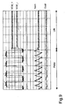
- Figure 8 shows time diagrams of signals involved in the control apparatus of the voice coil motor 3 in figure 7 .
- the asynchronous control L/P exactly takes place when the ripple of the current Ivcm is at its minimum level at the end of a recirculating step with both the two outputs VCM_+ and VCM_- being at a high level.
- Figure 9 shows time diagrams of voltages VM_+, VCM_-, current Ivcm and signal Eout during the transition from the current control in pulse width modality (PWM) to the control in linear modality operated by the control apparatus in figure 7 .
- PWM pulse width modality
- the change of operation modality from PWM to linear LIN takes place exactly halfway of a recirculating step, with VCM_+ and VCM_ being at a low level, where the current Ivcm is close or equal to the mean value IM.
- the device in accordance with the invention and the apparatus in figure 7 are also valid to change the operation modality from linear to PWM.
- Figure 10 shows the control device of the change of the driving modality of an electromagnetic load in accordance with the second embodiment of the present invention.
- Said device 200 comprises a first device or means 201 having an input command signal L/P of the change of the operating modality of an electromagnetic load 3 crossed by a current Ivcm from a first operating modality, i.e. the pulse width modulation operating modality or PWM modality, to a second operating modality, e.g. the linear operating modality, and a signal Tri_Peak, Tri_Mid representative of the flow of current Ivcm circulating within the load 3 at substantially its average value IM.
- a first operating modality i.e. the pulse width modulation operating modality or PWM modality
- Tri_Peak, Tri_Mid representative of the flow of current Ivcm circulating within the load 3 at substantially its average value IM.
- the electromagnetic load 3 is driven by a couple of switching circuits, preferably two half-bridges M1-M2, M3-M4; the central points of the two half-bridges are coupled to the ends of the electromagnetic load 3 and, during the first operating modality, each central point is subject to voltage variations ranging from a reference voltage, preferably the ground GND, to the supply voltage Vm.
- the control device 200 acts on the load by said two half-bridges M1-M2, M3-M4.
- Said device 201 comprises means 100 adapted to synchronize said command signal L/P of the change from the first operating modality to the second operating modality of the electromagnetic load with said signal representative of the flow of current Ivcm circulating within the load 3 at substantially its average value IM.
- the device is adapted to generate a command signal Slp as a function of said synchronization.
- the synchronization occurs with the flow of current Ivcm at the average value IM of the current circulating on the electromagnetic load which, if the electromagnetic load is the voice coil motor 3 in figure 1 and the driving apparatus is that in figure 1 , said flow of current Ivcm at the average value IM coincides with the peak (positive or negative) or the average value of the triangular voltage used for generating the signals PWM VCM_+ and VCM_-; therefore, the Tri_Peak or Tri_Mid signal is at the input of device 100.
- the device in accordance with the invention may be applied to the control apparatus of a voice coil motor 3 such as that in figure 1 , already described and known from patent EP 760552 , thus obtaining the control apparatus in figure 10 ; in such a case, device 100 allows the change of the operating modality from PWM to linear LIN to be synchronized.
- the pulse signal representing the peaks of the triangular waveform Tri or Tri180, the latter being out of phase by 180° with respect to the triangular waveform Tri, or the pulse signal representing the average value of the triangular waveform Tri or Tri180 are at the input of the device 100; the signals Tri_Peak e Tri_Mid are detected by appropriate means 300 and 301 within the driving circuits 2 or outside them but still belonging to the control apparatus and already known.
- the output of device 100 is a signal Slp which synchronizes the signal L/P with the peak or the average value of the triangular waveform Tri or Tri180. There is thus a synchronization with the PWM voltage frequency upon which the power stage 1 is working. More particularly, means 301 detect the signal Tri_Mid at each crossing of the triangular waveforms Tri and Tri180.
- the current Ivcm has a ripple superimposed to the average value: the current Ivcm of the voice coil motor 3 crosses the average value IM at half the conduction step, when the two outputs VCM_+ and VCM_- have a different potential, and at half the recirculation step, when the two outputs VCM_+ and VCM_- have the same potential (low or high).
- Tri_Peak and Tri_Mid Two pulse signals, Tri_Peak and Tri_Mid, are present within the control apparatus and they exactly indicate the passage of the triangular waveforms out of phase by 180° in these two points.
- the change from PWM modality to LIN linear modality may be synchronized by means of the device 201, synchronously to the PWM frequency at which the power stage 1 is working.
- Means 201 are adapted to command the driving of the electromagnetic load 3 with said first PWM operating modality in response to the synchronization still by the signal Slp and other means 203 are adapted to command the change from the first PWM operating modality to the second operating modality, e.g. LIN linear modality, of the electromagnetic load 3 by the signals Cb+ e Cb-, when at least one of the voltages VCM_+ and VCM_- reaches a value which is substantially equal to half the difference between the supply voltage Vm and a reference voltage, preferably the ground GND.
- the value VM/2 of voltages VCM_+ e VCM_- is detected by appropriate means, e.g.
- the outputs C1 and C2 of comparators 204 are at the input of means 203 which generate the signals Cb+ and Cb- with high outputs C1 and C2, i.e. when the voltages VCM_+ and VCM_- have a value which is substantially equal to VM/2.
- the means 203 when one of the outputs C1, C2 is high, the means 203 generate the signal Cb+ or Cb- which acts on one of the two driving circuits 2 which drives one of the two half-bridges M1, M2 and M3, M4 thus imposing the linear operation.
- output C2 is high, for example, the means 203 generate the signal Cb- which, by means of the driving circuit 2, imposes the linear operation to the half-bridge M3, M4; then, after a few nanoseconds, the output C1 will also be high and the means 203 generate the signal Cb+ which, by means of the driving circuit 2, imposes the linear operation to the half-bridge M1, M2.
- the two driving circuits 2 are commanded for changing the operating modality from PWM modality to the linear modality in a non-simultaneous manner, with the advantage of performing the transition for both the half-bridges M1, M2 and M3, M4 only when the output of the half-bridge is dynamic for an half (when the voltage VCM_+ or VCM_- reaches the voltage VM/2), i.e. under the better conditions for the transition, thus avoiding possible "spikes".
- the pulse width modulation operating modality or PWM modality two of the gate terminals of transistors M1-M4 are ground GND-commanded and two are commanded about the supply voltage VM.
- the transistors M1-M4 of the half-bridges are driven by drivers 2, some of these drivers being grounded and some at a voltage close to the threshold voltage Vt.
- the gate terminals of transistors M1 and M3 are commanded at a voltage close to the threshold voltage Vt, whereas the gate terminal of transistors M2 and M4 are ground GND-commanded.
- the voltage VCM+, VCM- on the central points of the half-bridges M1-M2 and M3-M4 takes a value which is equal to VM/2.
- Device 100 may be implemented with a flip-flop.
- the asynchronous command L/P which defines the operating modality is sent to the input D of the flip-flop; the clock Ck of this flip-flop is represented by the output signal from a gate OR 101 having the two input signals Tri_Peak and Tri_Mid being synchronous with the peaks of the triangular waveforms and with the crossing thereof or the average value thereof.
- the flip-flop has two outputs Q and Q-denied, with the output Q coinciding with the output Slp.
- the PWM modality when the signal L/P is at the high level, the PWM modality is selected, whereas when it is at the low level, the linear modality is selected, or vice versa.
- the output of the flip-flop generates a signal Slp which drives the transition of the operating modality from PWM to linear in the instants when the current ripple of the voice coil motor is close to the average value of the controlled current.
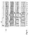
- Figure 11 shows the time diagrams of signals involved in the control apparatus of the voice coil motor 3 in figure 10 .
- Figure 11 shows the time diagrams of signal L/P, voltages VCM_+, VCM_- and current Ivcm.
- the asynchronous command L/P exactly occurs when the ripple of current Ivcm is at its minimum level at the end of a recirculation step with both the two outputs VCM_+ e VCM_- being at the high level.
- the patterns of the signals VM1-VM4 are shown, i.e. the voltages between the gate and source terminals of the respective transistors M1-M4; the PWM modulation is found after the generation of the signal L/P and the change from the PWM to the linear modality, when one of the voltages VCM_+ e VCM_- reaches a value which is substantially equal to VM/2.
- Figure 12 shows the time diagrams of the signal L/P of current Ivcm and current Ivcmold of a known apparatus, such as that in figure 1 . It should be noted that the discontinuity on the value of the controlled current Ivcm is limited and there are no glitches, as for current Ivcmold.
- the means 203 comprise four flip-flops 210-213 having the supply voltage Vdd at the input terminal D and the signals C1, C1n, C2 and C2n, respectively, where C1n and C2n are the signals C1 and C2 denied, at the terminals CK.
- the outputs Q of flip-flops 210 and 211 are at the input of a gate OR 216, whereas the outputs Q of flip-flops 212 and 213 are at the input of a gate OR 215; the output of gate OR 216 is the input CK of another flip-flop 217 having the signal Slp at the input terminal D, whereas the output of gate OR 215 is the input CK of another flip-flop 218 having the signal Slp at the input terminal D.
- the output Q of flip-flop 217 is the signal Cb+ and the output Q of flip-flop 218 is the signal Cb-.
- the flip-flop 210 enables the flip-flop 217 to send the signal Cb+ for changing the driving modality from PWM to linear modality to the driving circuit 2 of the half-bridge M1, M2.
- flip-flops 210-213 and flip-flops 217-218 allows to store the information of occurred flow at the dynamic half, i.e at the voltage VM/2, for each single half-bridge M1, M2 and M3, M4.
- the device 200 according to the second embodiment of the invention allows to further speed up the change of said driving modality of the electromagnetic load with respect to the device in accordance with the first embodiment of the invention.
Landscapes
- Engineering & Computer Science (AREA)
- Power Engineering (AREA)
- Control Of Linear Motors (AREA)
Claims (16)
- Dispositif de commande conçu pour changer le mode d'excitation d'une charge électromagnétique (3), ladite charge électromagnétique étant parcourue par un courant (Ivcm), caractérisé en ce que le dispositif de commande a, à l'entrée, un signal de commande (L/P) pour faire passer le mode d'excitation d'une charge électromagnétique (3) d'un premier mode de fonctionnement (PWM) à un second mode de fonctionnement (LIN) ou inversement et un signal (Tri_Peak, Tri_Mid) représentatif du passage de courant (Icvm) dans la charge (3) sensiblement à sa valeur moyenne (IM), à savoir un signal généré par les croisements ou les points d'intersection entre ledit courant (Ivcm) passant dans la charge (3) et sa valeur moyenne (IM), ledit dispositif comportant des premiers moyens (100, 201) aptes à synchroniser ledit signal de commande (L/P) pour passer du premier mode de fonctionnement au second mode de fonctionnement, ou inversement, de la charge électromagnétique, avec ledit signal (Tri_Peak, Tri_Mid) représentatif du passage de courant (Icvm) dans la charge (3) sensiblement à sa valeur moyenne (IM) et à générer un premier signal d'excitation (SIp) en fonction de ladite synchronisation après la détection dudit signal (Tri_Peak, Tri_Mid) généré par les croisements ou les points d'intersection entre ledit courant (Icvm) passant dans la charge (3) et sa valeur moyenne (IM).
- Dispositif selon la revendication 1, caractérisé en ce qu'il comporte une bascule (100) ayant en entrée ledit signal de commande (L/P) pour passer d'un premier mode de fonctionnement à un second mode de fonctionnement, ou inversement, de ladite charge électromagnétique (3) et un signal d'horloge (Ck) coïncident avec ledit signal (Tri_Peak, Tri_Mid) représentatif du passage de courant (Icvm) dans la charge (3) sensiblement à sa valeur moyenne (IM) et permettant de générer ledit premier signal d'excitation (SIp) en fonction de ladite synchronisation.
- Dispositif selon la revendication 1, caractérisé en ce que le passage du mode d'excitation d'une charge électromagnétique (3) d'un premier mode de fonctionnement à modulation de largeur d'impulsions (PWM) à un second mode de fonctionnement (LIN) est effectué à l'aide d'une paire de circuits de commutation (M1-M2, M3-M4), les bornes (VCM_+, YCM_-) de ladite charge électromagnétique étant couplées aux sorties respectives de ladite paire de circuits de commutation, pendant ledit premier mode de fonctionnement, chacune desdites deux sorties ayant une valeur de tension allant d'une première tension de référence (VM) à une seconde tension de référence (GND), ladite seconde tension de référence étant supérieure à ladite première tension de référence, ledit premier moyen (201) étant apte à synchroniser ledit signal de commande pour passer du premier mode de fonctionnement au second mode de fonctionnement de la charge électromagnétique avec ledit signal représentatif du flux de courant circulant dans la charge sensiblement à sa valeur moyenne et étant apte à générer le premier signal d'excitation (SIp) en réponse à ladite synchronisation, ledit premier moyen (201) étant apte à commander l'excitation de la charge par ledit premier mode de fonctionnement (PWM) en réponse audit premier signal d'excitation (SIp), ledit dispositif comportant des seconds moyens (203, 204) aptes à commander le passage du premier mode de fonctionnement au second mode de fonctionnement de la charge électromagnétique lorsque au moins une tension (VCM_+, VCM_-) à l'une desdites deux sorties des deux circuits de commutation atteint une valeur (VM/2) sensiblement égale à la moitié de la différence entre ladite seconde tension de référence et ladite première tension de référence.
- Dispositif selon la revendication 3, caractérisé en ce que lesdits seconds moyens (203, 204) sont aptes à commander le passage du premier mode de fonctionnement au second mode de fonctionnement à l'aide d'un deuxième signal d'excitation (Cb+) agissant sur le circuit de commutation (M1, M2) dans lequel la tension de la borne de sortie (VCM_+) atteint une valeur (VM/2) sensiblement égale à la moitié de la différence entre ladite seconde tension de référence et ladite première tension de référence, lesdits seconds moyens envoyant un troisième signal d'excitation (Cb-) pour le passage du premier mode de fonctionnement au second mode de fonctionnement et agissant sur l'autre circuit de commutation (M3, M4) une fois que la tension de sa borne de sortie (VCM_-) atteint également une valeur (VM/2) sensiblement égale à la moitié de la différence entre ladite seconde tension de référence et ladite première tension de référence.
- Dispositif selon l'une quelconque des revendications 1 à 3, caractérisé en ce que ledit premier mode de fonctionnement est un mode PWM et ledit signal (Tri_Peak, Tri_Mid) représentatif du passage de courant (Icvm) dans la charge (3) sensiblement à sa valeur moyenne (IM) étant un signal (Tri_Peak) représentatif de la valeur maximale positive ou négative du/des signaux triangulaires (Tri, Tri180) utilisés pour la modulation PWM.
- Dispositif selon l'une quelconque des revendications 1 à 3, caractérisé en ce que le premier mode de fonctionnement est un mode PWM et ledit signal (Tri_Peak, Tri_Mid) représentatif du passage de courant (Icvm) dans la charge (3) sensiblement à sa valeur moyenne (IM) étant un signal (Tri_Mid) représentatif de la valeur moyenne du/des signaux triangulaires (Tri, Tri180) utilisés pour la modulation PWM.
- Dispositif selon l'une quelconque des revendications 1 à 3, caractérisé en ce que le premier mode de fonctionnement est un mode PWM et ledit signal (Tri_Peak, Tri_Mid) représentatif du passage de courant (Icvm) dans la charge (3) sensiblement à sa valeur moyenne (IM) étant un signal (Tri_Mid) représentatif du croisement d'un premier signal triangulaire (Tri) et d'un second signal triangulaire (Tri180), déphasé de 180° par rapport au premier signal triangulaire, utilisé pour la modulation PWM.
- Dispositif selon l'une quelconque des revendications précédentes, caractérisé en ce que ledit second mode de fonctionnement est le mode linéaire (LIN).
- Dispositif selon la revendication 3, caractérisé en ce que lesdits seconds moyens (203, 204) comprennent d'autres moyens (204) conçus pour détecter l'instant où la tension (VCM_+, VCM_-) à l'une desdits deux sorties des deux circuits de commutation (M1-M2, M3-M4) atteint une valeur sensiblement égale à la moitié (VM/2) de la différence entre ladite seconde tension de référence (VM) et ladite première tension de référence (GND).
- Dispositif selon la revendication 9, caractérisé en ce que lesdits seconds moyens (203) sont conçus pour stocker les informations de survenance de flux à la valeur de tension donnée par la moitié (VM/2) de la différence entre ladite seconde tension de référence (VM) et ladite première tension de référence (GND) de chacune desdites deux sorties des deux circuits de commutation (M1-M2, M3-M4).
- Dispositif selon la revendication 9, caractérisé en ce que lesdits autres moyens (204) sont deux comparateurs et lesdits seconds moyens (203) comprennent une paire de première et deuxième bascules (210-211) ayant, à l'entrée, la tension d'alimentation et dans lequel la première bascule (210) a, à l'entrée, la sortie (C1) d'un premier desdits comparateurs et la deuxième bascule (210) a, à l'entrée, la sortie refusée (C1n) dudit premier comparateur, lesdits seconds moyens (203) comprenant une autre paire de troisième et quatrième bascules (212-313) ayant, à l'entrée, la tension d'alimentation et dans lequel la troisième bascule (210) a, à l'entrée, la sortie (C2) de l'autre desdits comparateurs et la quatrième bascule (210) a, à l'entrée, la sortie refusée (C1n) dudit autre comparateur, les sorties de ladite première paire de première et deuxième bascules (210-211) alimentant une première porte OU (216) et les sorties de ladite autre paire de troisième et quatrième bascules (212-213) alimentant une seconde porte OU (215), les sorties des deux portes OU (215, 216) alimentant une autre paire de cinquième et sixième bascules (217, 218) ayant ledit premier signal d'excitation (SIp) à l'entrée et produisant lesdits deuxième et troisième signaux d'excitation de sortie (Cb+, Cb-).
- Dispositif de commande d'une charge électromagnétique (3), ledit dispositif comportant un moyen d'excitation (2) pour exciter la charge électromagnétique parcourue par un courant électrique (Ivcm), ledit moyen d'excitation permettant de faire passer le mode de fonctionnement de la charge électromagnétique d'un premier (PWM) à un second (LIN) mode ou inversement en fonction d'un signal extérieur de commande (L/P) pour changer de mode de fonctionnement de la charge électromagnétique (3), caractérisé en ce qu'il comporte un dispositif de commande pour le changement de mode d'excitation d'une charge électromagnétique (3) selon l'une quelconque des revendications précédentes.
- Dispositif selon la revendication 12, caractérisé en ce que ladite charge électromagnétique est un moteur (3) à bobine mobile, ledit premier mode de fonctionnement est un mode PWM et ledit second mode de fonctionnement est un mode linéaire, ledit moyen d'excitation (2) comprend un moyen (Rs) pour détecter le courant (Ivcm) passant dans le moteur (3) à bobine mobile et permettant de générer au moins un signal PWM (VCM_+, VCM -) en fonction d'un signal triangulaire (Tri, Tri180) et d'un signal d'erreur (Eout) représentatif de la différence entre ledit courant détecté et un signal extérieur (Dout), ledit dispositif comportant des moyens (300, 301) pour détecter la valeur maximale positive ou négative ou la valeur moyenne dudit signal triangulaire.
- Dispositif selon la revendication 13, caractérisé en ce qu'il comporte au moins un étage de puissance (1) excité par le moyen d'excitation (2) et couplé audit moteur (3) à bobine mobile, ledit étage de puissance (1) comprenant un montage en pont formé de deux demi-ponts (M1-M2, M3-M4) à transistors, lesdits demi-ponts ayants deux bornes de sortie respectives auxquelles est couplé ledit moteur à bobine mobile, ledit moyen d'excitation (2) agissant sur lesdits deux demi-ponts de manière à fournir audit moteur à bobine mobile deux signaux PWM obtenus à l'aide d'un premier signal triangulaire (Tri) et d'un second signal triangulaire (Tri80), déphasé de 180° par rapport au premier signal triangulaire, et un signal d'erreur (Eout) représentatif de la différence entre ledit courant détecté et un signal extérieur (Dout).
- Procédé pour commander le changement de mode de fonctionnement d'une charge électromagnétique (3), ladite charge électromagnétique étant parcourue par un courant (Ivcm), ledit procédé comportant la synchronisation du signal de commande (L/P) afin de faire passer une charge électromagnétique (3) d'un premier mode de fonctionnement (PWM) à un second mode de fonctionnement (LIN) ou inversement avec un signal (Tri_Peak, Tri_Mid) représentatif du passage du courant (Ivcm) dans la charge (3) sensiblement à sa valeur moyenne (IM), à savoir un signal généré par les croisements ou les points d'intersection entre ce courant (Icvm) passant dans la charge (3) et sa valeur moyenne (IM), de manière à générer un premier signal d'excitation (SIp) en fonction de ladite synchronisation après la détection du signal (Tri_Peak, Tri_Mid) généré par les croisements ou les points d'intersection entre le courant (Icvm) passant dans la charge (3) et sa valeur moyenne (IM).
- Procédé selon la revendication 15, caractérisé en ce que ledit premier mode de fonctionnement est une modulation de largeur d'impulsion (PWM), ledit changement de mode d'excitation est effectué à l'aide d'une paire de circuits de commutation (M1-M2, M3-M4), les bornes (VCM_+, VCM_-) de ladite charge électromagnétique étant couplées aux sorties respectives de ladite paire de circuits de commutation, pendant ledit premier mode de fonctionnement, chacune desdites deux sorties ayant une valeur de tension allant d'une première tension de référence (VM) à une seconde tension de référence (GND), ladite seconde tension de référence étant supérieure à ladite première tension de référence, ledit procédé comportant la synchronisation dudit premier signal de commande (L/P) de passage du mode de fonctionnement d'une charge électromagnétique (3) du premier mode de fonctionnement (PWM) au second mode de fonctionnement (LIN) et un signal (Tri_Peak, Tri_Mid) représentatif du flux de courant (Ivcm) circulant dans la charge (3) sensiblement à sa valeur moyenne (IM) de façon à générer le premier signal d'excitation (SIp) en fonction de ladite synchronisation, l'excitation de la charge par ledit premier mode de fonctionnement (PWM) en réponse audit premier signal d'excitation (SIp), et la commande du passage du premier mode de fonctionnement au second mode de fonctionnement de la charge électromagnétique lorsque au moins une tension (VCM_+, VCM_-) à l'une ou l'autre des deux sorties des deux circuits de commutation atteint une valeur (VM/2) sensiblement égale à la moitié de la différence entre ladite seconde tension de référence et ladite première tension de référence.
Applications Claiming Priority (2)
| Application Number | Priority Date | Filing Date | Title |
|---|---|---|---|
| ITMI20090507 | 2009-03-31 | ||
| ITMI20091987 | 2009-11-12 |
Publications (2)
| Publication Number | Publication Date |
|---|---|
| EP2237405A1 EP2237405A1 (fr) | 2010-10-06 |
| EP2237405B1 true EP2237405B1 (fr) | 2013-02-20 |
Family
ID=42309706
Family Applications (1)
| Application Number | Title | Priority Date | Filing Date |
|---|---|---|---|
| EP10158288A Active EP2237405B1 (fr) | 2009-03-31 | 2010-03-30 | Dispositif de commande pour le changement de la modalité de commande d'une charge électromagnétique |
Country Status (2)
| Country | Link |
|---|---|
| US (1) | US8471505B2 (fr) |
| EP (1) | EP2237405B1 (fr) |
Families Citing this family (4)
| Publication number | Priority date | Publication date | Assignee | Title |
|---|---|---|---|---|
| EP2438059A1 (fr) | 2009-06-05 | 2012-04-11 | Link Medicine Corporation | Dérivés d'aminopyrrolidinone et utilisations de ceux-ci |
| US8724016B2 (en) * | 2011-04-06 | 2014-05-13 | Apple Inc. | Driver circuit for a camera voice coil motor |
| TWI571025B (zh) * | 2016-01-21 | 2017-02-11 | 旺玖科技股份有限公司 | 負電壓保護系統 |
| TWI799742B (zh) * | 2020-10-12 | 2023-04-21 | 茂達電子股份有限公司 | 降低電磁干擾電路 |
Family Cites Families (14)
| Publication number | Priority date | Publication date | Assignee | Title |
|---|---|---|---|---|
| US4658308A (en) * | 1986-03-05 | 1987-04-14 | Miniscribe Corporation | Method and apparatus for retracting head and braking motor of a disc drive device |
| US4786995A (en) * | 1986-11-06 | 1988-11-22 | Peripheral Technology, Inc | Automatic head retract system for disk drive |
| US5091680A (en) * | 1990-02-06 | 1992-02-25 | Seagate Technology, Inc. | Motor brake circuit for magnetic disk drive system |
| US5406150A (en) * | 1992-08-24 | 1995-04-11 | Silicon Systems Inc | Control system for motors and inductive loads |
| US5731670A (en) * | 1995-03-31 | 1998-03-24 | Sgs-Thomson Microelectronics S.R.L. | Method for driving a brushless DC electric motor |
| US5798623A (en) * | 1996-02-12 | 1998-08-25 | Quantum Corporation | Switch mode sine wave driver for polyphase brushless permanent magnet motor |
| US6084378A (en) * | 1997-05-30 | 2000-07-04 | Stmicroelectronics, Inc. | Variable slew rate pulse width modulation system |
| JP4265877B2 (ja) * | 2001-05-30 | 2009-05-20 | 株式会社ルネサステクノロジ | 磁気ディスク記憶装置 |
| JP3871200B2 (ja) * | 2001-05-30 | 2007-01-24 | 株式会社ルネサステクノロジ | 磁気ディスク記憶装置 |
| JP2005304095A (ja) * | 2004-04-06 | 2005-10-27 | Renesas Technology Corp | モータ駆動用半導体集積回路および磁気ディスク記憶装置 |
| US7092197B2 (en) * | 2004-05-28 | 2006-08-15 | Texas Instruments Incorporated | Rejection of power supply variations for gain error cancellation in pulse-width-modulated motor controllers |
| US6989955B2 (en) | 2004-05-28 | 2006-01-24 | Texas Instruments Incorporated | Efficient transition from class D to linear operation in dual-mode voice coil motor controllers |
| JP4873457B2 (ja) * | 2006-04-20 | 2012-02-08 | ルネサスエレクトロニクス株式会社 | 磁気ディスク制御装置 |
| EP1863164A1 (fr) * | 2006-05-30 | 2007-12-05 | STMicroelectronics S.r.l. | Amélioration du rendement de récupération d'énergie pendant la phase transitoire d'un moteur pour l'entraînement de disque pour stationner la tête de lecture/écriture d'un disque magnétique en cas du défaut d'une source auxiliaire |
-
2010
- 2010-03-30 EP EP10158288A patent/EP2237405B1/fr active Active
- 2010-03-31 US US12/751,807 patent/US8471505B2/en active Active
Also Published As
| Publication number | Publication date |
|---|---|
| US8471505B2 (en) | 2013-06-25 |
| EP2237405A1 (fr) | 2010-10-06 |
| US20100244761A1 (en) | 2010-09-30 |
Similar Documents
| Publication | Publication Date | Title |
|---|---|---|
| EP1339163B1 (fr) | Régulation de modulation de largeur d'impulsion lineaire pour une charge électromagnetique | |
| US6995537B1 (en) | Closed-loop control system to mitigate PWM switching noise | |
| US7863841B2 (en) | Class H drive | |
| US5977737A (en) | Digital motor driver circuit and method | |
| EP1774518B1 (fr) | Transition efficace d'un fonctionnement de classe d a un fonctionnement lineaire dans des controleurs de moteur de bobine mobile a double mode | |
| US8093847B2 (en) | Motor drive circuit, method, and disc device using the same | |
| JP3831020B2 (ja) | ブリッジ回路の駆動方法、ブリッジ回路の駆動回路及びディスク・ドライブ | |
| EP2237405B1 (fr) | Dispositif de commande pour le changement de la modalité de commande d'une charge électromagnétique | |
| JP4963246B2 (ja) | モータ駆動回路、駆動方法ならびにそれらを用いたディスク装置 | |
| WO1997041558A1 (fr) | Circuit de commande lineaire/a modulation d'impulsions en largeur pour actionneur a bobine mobile d'unites de disque | |
| JP4880339B2 (ja) | モータ駆動回路および方法ならびにそれを用いたディスク装置 | |
| JP4265877B2 (ja) | 磁気ディスク記憶装置 | |
| KR0162607B1 (ko) | 보이스코일모터 구동 제어회로 | |
| US7542262B2 (en) | Apparatus for driving an electromagnetic load | |
| US20190356310A1 (en) | Bridge output circuit, motor driver device and semiconductor device | |
| US11037596B2 (en) | Motor driver device and semiconductor device | |
| US20220216839A1 (en) | Stabilizing common mode of differential switching output stage | |
| JP2007295643A (ja) | 磁気ディスク制御装置 | |
| JP2007074835A (ja) | ボイスコイルモータ駆動回路および磁気ディスク記憶装置 | |
| JP2006081396A (ja) | 3相モータ用の回転駆動制御装置 | |
| EP1865505B1 (fr) | Prévention du bruit à cause des signaux concurrents d'un excitation d'un pont-H entraînant un moteur à bobine mobile | |
| US10855213B2 (en) | Motor driver device and semiconductor device | |
| JP5171079B2 (ja) | モータ駆動回路、駆動方法ならびにそれらを用いたディスク装置 | |
| JP2019201478A (ja) | モータドライバ装置及び半導体装置 |
Legal Events
| Date | Code | Title | Description |
|---|---|---|---|
| PUAI | Public reference made under article 153(3) epc to a published international application that has entered the european phase |
Free format text: ORIGINAL CODE: 0009012 |
|
| AK | Designated contracting states |
Kind code of ref document: A1 Designated state(s): AT BE BG CH CY CZ DE DK EE ES FI FR GB GR HR HU IE IS IT LI LT LU LV MC MK MT NL NO PL PT RO SE SI SK SM TR |
|
| AX | Request for extension of the european patent |
Extension state: AL BA ME RS |
|
| 17P | Request for examination filed |
Effective date: 20110331 |
|
| 17Q | First examination report despatched |
Effective date: 20110822 |
|
| RAP1 | Party data changed (applicant data changed or rights of an application transferred) |
Owner name: STMICROELECTRONICS SRL |
|
| RIC1 | Information provided on ipc code assigned before grant |
Ipc: H02P 6/08 20060101AFI20120612BHEP Ipc: H02P 25/02 20060101ALI20120612BHEP Ipc: G11B 5/596 20060101ALI20120612BHEP Ipc: G11B 5/55 20060101ALI20120612BHEP Ipc: H02P 6/22 20060101ALI20120612BHEP |
|
| GRAP | Despatch of communication of intention to grant a patent |
Free format text: ORIGINAL CODE: EPIDOSNIGR1 |
|
| GRAS | Grant fee paid |
Free format text: ORIGINAL CODE: EPIDOSNIGR3 |
|
| GRAA | (expected) grant |
Free format text: ORIGINAL CODE: 0009210 |
|
| AK | Designated contracting states |
Kind code of ref document: B1 Designated state(s): AT BE BG CH CY CZ DE DK EE ES FI FR GB GR HR HU IE IS IT LI LT LU LV MC MK MT NL NO PL PT RO SE SI SK SM TR |
|
| REG | Reference to a national code |
Ref country code: GB Ref legal event code: FG4D |
|
| REG | Reference to a national code |
Ref country code: CH Ref legal event code: EP |
|
| REG | Reference to a national code |
Ref country code: AT Ref legal event code: REF Ref document number: 597898 Country of ref document: AT Kind code of ref document: T Effective date: 20130315 |
|
| REG | Reference to a national code |
Ref country code: IE Ref legal event code: FG4D |
|
| REG | Reference to a national code |
Ref country code: DE Ref legal event code: R096 Ref document number: 602010005063 Country of ref document: DE Effective date: 20130418 |
|
| REG | Reference to a national code |
Ref country code: AT Ref legal event code: MK05 Ref document number: 597898 Country of ref document: AT Kind code of ref document: T Effective date: 20130220 |
|
| REG | Reference to a national code |
Ref country code: NL Ref legal event code: VDEP Effective date: 20130220 |
|
| REG | Reference to a national code |
Ref country code: LT Ref legal event code: MG4D |
|
| PG25 | Lapsed in a contracting state [announced via postgrant information from national office to epo] |
Ref country code: LT Free format text: LAPSE BECAUSE OF FAILURE TO SUBMIT A TRANSLATION OF THE DESCRIPTION OR TO PAY THE FEE WITHIN THE PRESCRIBED TIME-LIMIT Effective date: 20130220 Ref country code: IS Free format text: LAPSE BECAUSE OF FAILURE TO SUBMIT A TRANSLATION OF THE DESCRIPTION OR TO PAY THE FEE WITHIN THE PRESCRIBED TIME-LIMIT Effective date: 20130620 Ref country code: NO Free format text: LAPSE BECAUSE OF FAILURE TO SUBMIT A TRANSLATION OF THE DESCRIPTION OR TO PAY THE FEE WITHIN THE PRESCRIBED TIME-LIMIT Effective date: 20130520 Ref country code: AT Free format text: LAPSE BECAUSE OF FAILURE TO SUBMIT A TRANSLATION OF THE DESCRIPTION OR TO PAY THE FEE WITHIN THE PRESCRIBED TIME-LIMIT Effective date: 20130220 Ref country code: ES Free format text: LAPSE BECAUSE OF FAILURE TO SUBMIT A TRANSLATION OF THE DESCRIPTION OR TO PAY THE FEE WITHIN THE PRESCRIBED TIME-LIMIT Effective date: 20130531 Ref country code: BG Free format text: LAPSE BECAUSE OF FAILURE TO SUBMIT A TRANSLATION OF THE DESCRIPTION OR TO PAY THE FEE WITHIN THE PRESCRIBED TIME-LIMIT Effective date: 20130520 Ref country code: SE Free format text: LAPSE BECAUSE OF FAILURE TO SUBMIT A TRANSLATION OF THE DESCRIPTION OR TO PAY THE FEE WITHIN THE PRESCRIBED TIME-LIMIT Effective date: 20130220 |
|
| PG25 | Lapsed in a contracting state [announced via postgrant information from national office to epo] |
Ref country code: PT Free format text: LAPSE BECAUSE OF FAILURE TO SUBMIT A TRANSLATION OF THE DESCRIPTION OR TO PAY THE FEE WITHIN THE PRESCRIBED TIME-LIMIT Effective date: 20130620 Ref country code: FI Free format text: LAPSE BECAUSE OF FAILURE TO SUBMIT A TRANSLATION OF THE DESCRIPTION OR TO PAY THE FEE WITHIN THE PRESCRIBED TIME-LIMIT Effective date: 20130220 Ref country code: SI Free format text: LAPSE BECAUSE OF FAILURE TO SUBMIT A TRANSLATION OF THE DESCRIPTION OR TO PAY THE FEE WITHIN THE PRESCRIBED TIME-LIMIT Effective date: 20130220 Ref country code: LV Free format text: LAPSE BECAUSE OF FAILURE TO SUBMIT A TRANSLATION OF THE DESCRIPTION OR TO PAY THE FEE WITHIN THE PRESCRIBED TIME-LIMIT Effective date: 20130220 Ref country code: BE Free format text: LAPSE BECAUSE OF FAILURE TO SUBMIT A TRANSLATION OF THE DESCRIPTION OR TO PAY THE FEE WITHIN THE PRESCRIBED TIME-LIMIT Effective date: 20130220 Ref country code: GR Free format text: LAPSE BECAUSE OF FAILURE TO SUBMIT A TRANSLATION OF THE DESCRIPTION OR TO PAY THE FEE WITHIN THE PRESCRIBED TIME-LIMIT Effective date: 20130521 Ref country code: PL Free format text: LAPSE BECAUSE OF FAILURE TO SUBMIT A TRANSLATION OF THE DESCRIPTION OR TO PAY THE FEE WITHIN THE PRESCRIBED TIME-LIMIT Effective date: 20130220 |
|
| PG25 | Lapsed in a contracting state [announced via postgrant information from national office to epo] |
Ref country code: HR Free format text: LAPSE BECAUSE OF FAILURE TO SUBMIT A TRANSLATION OF THE DESCRIPTION OR TO PAY THE FEE WITHIN THE PRESCRIBED TIME-LIMIT Effective date: 20130220 |
|
| PG25 | Lapsed in a contracting state [announced via postgrant information from national office to epo] |
Ref country code: EE Free format text: LAPSE BECAUSE OF FAILURE TO SUBMIT A TRANSLATION OF THE DESCRIPTION OR TO PAY THE FEE WITHIN THE PRESCRIBED TIME-LIMIT Effective date: 20130220 Ref country code: MC Free format text: LAPSE BECAUSE OF NON-PAYMENT OF DUE FEES Effective date: 20130331 Ref country code: SK Free format text: LAPSE BECAUSE OF FAILURE TO SUBMIT A TRANSLATION OF THE DESCRIPTION OR TO PAY THE FEE WITHIN THE PRESCRIBED TIME-LIMIT Effective date: 20130220 Ref country code: DK Free format text: LAPSE BECAUSE OF FAILURE TO SUBMIT A TRANSLATION OF THE DESCRIPTION OR TO PAY THE FEE WITHIN THE PRESCRIBED TIME-LIMIT Effective date: 20130220 Ref country code: CZ Free format text: LAPSE BECAUSE OF FAILURE TO SUBMIT A TRANSLATION OF THE DESCRIPTION OR TO PAY THE FEE WITHIN THE PRESCRIBED TIME-LIMIT Effective date: 20130220 Ref country code: RO Free format text: LAPSE BECAUSE OF FAILURE TO SUBMIT A TRANSLATION OF THE DESCRIPTION OR TO PAY THE FEE WITHIN THE PRESCRIBED TIME-LIMIT Effective date: 20130220 Ref country code: NL Free format text: LAPSE BECAUSE OF FAILURE TO SUBMIT A TRANSLATION OF THE DESCRIPTION OR TO PAY THE FEE WITHIN THE PRESCRIBED TIME-LIMIT Effective date: 20130220 |
|
| PLBE | No opposition filed within time limit |
Free format text: ORIGINAL CODE: 0009261 |
|
| REG | Reference to a national code |
Ref country code: FR Ref legal event code: ST Effective date: 20131129 |
|
| STAA | Information on the status of an ep patent application or granted ep patent |
Free format text: STATUS: NO OPPOSITION FILED WITHIN TIME LIMIT |
|
| REG | Reference to a national code |
Ref country code: IE Ref legal event code: MM4A |
|
| 26N | No opposition filed |
Effective date: 20131121 |
|
| PG25 | Lapsed in a contracting state [announced via postgrant information from national office to epo] |
Ref country code: FR Free format text: LAPSE BECAUSE OF NON-PAYMENT OF DUE FEES Effective date: 20130422 Ref country code: IE Free format text: LAPSE BECAUSE OF NON-PAYMENT OF DUE FEES Effective date: 20130330 |
|
| REG | Reference to a national code |
Ref country code: DE Ref legal event code: R097 Ref document number: 602010005063 Country of ref document: DE Effective date: 20131121 |
|
| PG25 | Lapsed in a contracting state [announced via postgrant information from national office to epo] |
Ref country code: MT Free format text: LAPSE BECAUSE OF FAILURE TO SUBMIT A TRANSLATION OF THE DESCRIPTION OR TO PAY THE FEE WITHIN THE PRESCRIBED TIME-LIMIT Effective date: 20130220 |
|
| REG | Reference to a national code |
Ref country code: CH Ref legal event code: PL |
|
| GBPC | Gb: european patent ceased through non-payment of renewal fee |
Effective date: 20140330 |
|
| PG25 | Lapsed in a contracting state [announced via postgrant information from national office to epo] |
Ref country code: GB Free format text: LAPSE BECAUSE OF NON-PAYMENT OF DUE FEES Effective date: 20140330 Ref country code: LI Free format text: LAPSE BECAUSE OF NON-PAYMENT OF DUE FEES Effective date: 20140331 Ref country code: CH Free format text: LAPSE BECAUSE OF NON-PAYMENT OF DUE FEES Effective date: 20140331 |
|
| PG25 | Lapsed in a contracting state [announced via postgrant information from national office to epo] |
Ref country code: SM Free format text: LAPSE BECAUSE OF FAILURE TO SUBMIT A TRANSLATION OF THE DESCRIPTION OR TO PAY THE FEE WITHIN THE PRESCRIBED TIME-LIMIT Effective date: 20130220 |
|
| PG25 | Lapsed in a contracting state [announced via postgrant information from national office to epo] |
Ref country code: CY Free format text: LAPSE BECAUSE OF FAILURE TO SUBMIT A TRANSLATION OF THE DESCRIPTION OR TO PAY THE FEE WITHIN THE PRESCRIBED TIME-LIMIT Effective date: 20130220 Ref country code: TR Free format text: LAPSE BECAUSE OF FAILURE TO SUBMIT A TRANSLATION OF THE DESCRIPTION OR TO PAY THE FEE WITHIN THE PRESCRIBED TIME-LIMIT Effective date: 20130220 |
|
| PG25 | Lapsed in a contracting state [announced via postgrant information from national office to epo] |
Ref country code: MK Free format text: LAPSE BECAUSE OF FAILURE TO SUBMIT A TRANSLATION OF THE DESCRIPTION OR TO PAY THE FEE WITHIN THE PRESCRIBED TIME-LIMIT Effective date: 20130220 Ref country code: LU Free format text: LAPSE BECAUSE OF NON-PAYMENT OF DUE FEES Effective date: 20130330 Ref country code: HU Free format text: LAPSE BECAUSE OF FAILURE TO SUBMIT A TRANSLATION OF THE DESCRIPTION OR TO PAY THE FEE WITHIN THE PRESCRIBED TIME-LIMIT; INVALID AB INITIO Effective date: 20100330 |
|
| REG | Reference to a national code |
Ref country code: DE Ref legal event code: R082 Ref document number: 602010005063 Country of ref document: DE Representative=s name: SCHMITT-NILSON SCHRAUD WAIBEL WOHLFROM PATENTA, DE |
|
| PGFP | Annual fee paid to national office [announced via postgrant information from national office to epo] |
Ref country code: IT Payment date: 20200218 Year of fee payment: 11 |
|
| PG25 | Lapsed in a contracting state [announced via postgrant information from national office to epo] |
Ref country code: IT Free format text: LAPSE BECAUSE OF NON-PAYMENT OF DUE FEES Effective date: 20210330 |
|
| PGFP | Annual fee paid to national office [announced via postgrant information from national office to epo] |
Ref country code: DE Payment date: 20240220 Year of fee payment: 15 |