EP2237391A1 - Stator and manufacturing method thereof - Google Patents
Stator and manufacturing method thereof Download PDFInfo
- Publication number
- EP2237391A1 EP2237391A1 EP09797875A EP09797875A EP2237391A1 EP 2237391 A1 EP2237391 A1 EP 2237391A1 EP 09797875 A EP09797875 A EP 09797875A EP 09797875 A EP09797875 A EP 09797875A EP 2237391 A1 EP2237391 A1 EP 2237391A1
- Authority
- EP
- European Patent Office
- Prior art keywords
- coil
- disposed
- phase
- stator core
- slot
- Prior art date
- Legal status (The legal status is an assumption and is not a legal conclusion. Google has not performed a legal analysis and makes no representation as to the accuracy of the status listed.)
- Granted
Links
Images


Classifications
-
- H—ELECTRICITY
- H02—GENERATION; CONVERSION OR DISTRIBUTION OF ELECTRIC POWER
- H02K—DYNAMO-ELECTRIC MACHINES
- H02K15/00—Methods or apparatus specially adapted for manufacturing, assembling, maintaining or repairing of dynamo-electric machines
- H02K15/08—Forming windings by laying conductors into or around core parts
- H02K15/085—Forming windings by laying conductors into or around core parts by laying conductors into slotted stators
-
- H—ELECTRICITY
- H02—GENERATION; CONVERSION OR DISTRIBUTION OF ELECTRIC POWER
- H02K—DYNAMO-ELECTRIC MACHINES
- H02K15/00—Methods or apparatus specially adapted for manufacturing, assembling, maintaining or repairing of dynamo-electric machines
- H02K15/0025—Shaping or compacting conductors or winding heads after the installation of the winding in the core or machine ; Applying fastening means on winding heads
- H02K15/0031—Shaping or compacting conductors in slots or around salient poles
-
- H—ELECTRICITY
- H02—GENERATION; CONVERSION OR DISTRIBUTION OF ELECTRIC POWER
- H02K—DYNAMO-ELECTRIC MACHINES
- H02K15/00—Methods or apparatus specially adapted for manufacturing, assembling, maintaining or repairing of dynamo-electric machines
- H02K15/04—Methods or apparatus specially adapted for manufacturing, assembling, maintaining or repairing of dynamo-electric machines of windings, prior to mounting into machines
- H02K15/0414—Windings consisting of separate elements, e.g. bars, hairpins, segments, half coils
- H02K15/0421—Windings consisting of separate elements, e.g. bars, hairpins, segments, half coils consisting of single conductors, e.g. hairpins
-
- H—ELECTRICITY
- H02—GENERATION; CONVERSION OR DISTRIBUTION OF ELECTRIC POWER
- H02K—DYNAMO-ELECTRIC MACHINES
- H02K15/00—Methods or apparatus specially adapted for manufacturing, assembling, maintaining or repairing of dynamo-electric machines
- H02K15/04—Methods or apparatus specially adapted for manufacturing, assembling, maintaining or repairing of dynamo-electric machines of windings, prior to mounting into machines
- H02K15/0435—Wound windings
- H02K15/0478—Wave windings, undulated windings
-
- H—ELECTRICITY
- H02—GENERATION; CONVERSION OR DISTRIBUTION OF ELECTRIC POWER
- H02K—DYNAMO-ELECTRIC MACHINES
- H02K15/00—Methods or apparatus specially adapted for manufacturing, assembling, maintaining or repairing of dynamo-electric machines
- H02K15/06—Embedding prefabricated windings in machines
- H02K15/062—Windings in slots; salient pole windings
- H02K15/064—Windings consisting of separate segments, e.g. hairpin windings
-
- H—ELECTRICITY
- H02—GENERATION; CONVERSION OR DISTRIBUTION OF ELECTRIC POWER
- H02K—DYNAMO-ELECTRIC MACHINES
- H02K15/00—Methods or apparatus specially adapted for manufacturing, assembling, maintaining or repairing of dynamo-electric machines
- H02K15/06—Embedding prefabricated windings in machines
- H02K15/062—Windings in slots; salient pole windings
- H02K15/065—Windings consisting of complete sections, e.g. coils, waves
- H02K15/067—Windings consisting of complete sections, e.g. coils, waves inserted in parallel to the axis of the slots or inter-polar channels
-
- H—ELECTRICITY
- H02—GENERATION; CONVERSION OR DISTRIBUTION OF ELECTRIC POWER
- H02K—DYNAMO-ELECTRIC MACHINES
- H02K3/00—Details of windings
- H02K3/04—Windings characterised by the conductor shape, form or construction, e.g. with bar conductors
- H02K3/12—Windings characterised by the conductor shape, form or construction, e.g. with bar conductors arranged in slots
-
- Y—GENERAL TAGGING OF NEW TECHNOLOGICAL DEVELOPMENTS; GENERAL TAGGING OF CROSS-SECTIONAL TECHNOLOGIES SPANNING OVER SEVERAL SECTIONS OF THE IPC; TECHNICAL SUBJECTS COVERED BY FORMER USPC CROSS-REFERENCE ART COLLECTIONS [XRACs] AND DIGESTS
- Y10—TECHNICAL SUBJECTS COVERED BY FORMER USPC
- Y10T—TECHNICAL SUBJECTS COVERED BY FORMER US CLASSIFICATION
- Y10T29/00—Metal working
- Y10T29/49—Method of mechanical manufacture
- Y10T29/49002—Electrical device making
- Y10T29/49009—Dynamoelectric machine
Definitions
- the present invention relates to a stator and a manufacturing method of the stator in which coil conductors of three phases, namely a U phase, a V phase, and a W phase, are disposed in a distributed winding form in a plurality of slots of a stator core.
- a jig is used to insert the coil conductors of the three phases into an inner peripheral side of the stator core while holding the coil conductors.
- the coil before winding a coil around a stator core, the coil is molded to include a ridged front side coil end portion to be positioned on the inside of an inner diameter of the stator core, a slot coil portion to be disposed in a slot, and a ridged rear side coil end portion. Further, a relay coil portion bent in an inside direction is formed between the front side coil end portion and the slot coil portion. The coil is then inserted into the stator core from an end surface of the stator core, starting with the relay coil portion, and once the coil has been inserted into the stator core, the front side coil end portion is deformed to the outside of the inner diameter of the core.
- the coil can be inserted into the stator core after being molded in advance into a post-core insertion shape, and therefore the coil does not deform when inserted into the stator core, thus preventing, damage to an insulating film of the coil and the stator core.
- Patent Document 1 Japanese Patent Publication No. 2523933
- Patent Document 1 after the coil is inserted into the stator core, the front side coil end portion of the coil is deformed to the outside of the inner diameter of the coil. Therefore, although deformation does not occur in the coil when the coil is inserted into the stator core, the coil is deformed after being inserted into the stator core, and as a result, a conductor portion or an insulating film in the deformed part may deteriorate. Furthermore, if the front side coil end portion is left on the inside of the inner diameter of the stator core without being deformed to the outside of the core inner diameter, the front side coil end portion needs be disposed distant from a rotor to prevent interference between the front side coil end portion and the rotor when the front side coil end portion is deformed due to vibration. As a result, the axial size of the stator increases.
- the present invention has been designed in consideration of these conventional problems, and it is an object of the present invention to provide a stator and a manufacturing method of the stator in which coil conductors of three phases can be disposed in a stator core easily, and the size of the stator can be reduced while maintaining a high level of quality in the coil conductors of the three phases.
- a stator in which coil conductors of three phases, namely a U phase, a V phase, and a W phase, are disposed in a distributed winding form in a plurality of slots extending in an axial direction of a stator core is characterized in that the coil conductors of the three phases each include a slot conductor portion disposed in the slot, and a pair of coil end conductor portions disposed on both axial sides of the stator core to connect the slot conductor portions disposed in the different slots to each other, and a first side transition wire portion of each of the phases, which extends in a circumferential direction in a first side coil end conductor portion serving as the coil end conductor portion positioned on an axial first side, is disposed further toward a radial inner side than an inner peripheral end surface of a tooth provided on each circumferential side of the slot so as to overlap another first side transition wire portion in the axial direction.
- a manufacturing method for a stator in which coil conductors of three phases, namely a U phase, a V phase, and a W phase, are disposed in a distributed winding form in a plurality of slots extending in an axial direction of a stator core, the coil conductors of the three phases each include a slot conductor portion disposed in the slot, and a pair of coil end conductor portions disposed on both axial sides of the stator core to connect the slot conductor portions disposed in the different slots to each other is characterized by including the steps of: molding the coil conductors of the three phases such that a first side transition wire portion of each of the phases, which extends in a circumferential direction in a first side coil end conductor portion serving as the coil end conductor portion positioned on an axial first side, is disposed further toward a radial inner side than an inner peripheral end surface of a tooth provided on each circumferential side of the slot, and molding the coil conductors of the three phases
- the stator according to the present invention by manipulating the shape of the coil end conductor portion, the coil conductors of the three phases are inserted into the stator core easily and the need for further molding of the coil conductors after insertion into the stator core is eliminated.
- the first side coil end conductor portion is shaped such that the first side transition wire portion of each of phases, which extends in the circumferential direction, is disposed further toward the radial inner side than the inner peripheral end surface of the tooth, and all of the first side coil end conductor portions are positioned further toward the radial inner side than an outer peripheral end surface of the slot.
- the coil conductors of the three phases when the coil conductors of the three phases are inserted into the stator core, the coil conductors of the three phases ean be inserted into the stator core from the axial first side on which the first side coil end conductor portions are positioned.
- the coil conductors of the three phases ean be disposed relative to the stator core easily.
- the stator according to the present invention can be manufactured without performing molding processing such as bending molding and compression molding on the first side coil end conductor portion after insertion into the stator core with substantially no further processing after insertion.
- molding processing such as bending molding and compression molding
- an insulating film provided on the surface of the conductor portion constituting the coil conductor suffers substantially no breakage or deterioration. Therefore, the quality of the stator according to the present invention can be improved.
- the coil conductors of the three phases can be assembled in advance prior to insertion into the stator core such that all of the coil conductors of the three phases can be inserted into the stator core at once.
- the coil conductors of the three phases can be inserted into the stator core very easily.
- the coil conductors may be inserted into the stator core in predetermined units (numbers) and then joined by welding or the like when disposed in the stator core.
- first side transition wire portion of each of the phases is disposed to overlap another first side transition wire portion (of the same phase or another phase) in the axial direction.
- first side coil end conductor portion can be prevented from projecting in an inner circumferential (inner radial) direction, thereby preventing deformation of the first side coil end conductor portion due to vibration. Therefore, when a rotor is incorporated into the manufactured stator, the distance between the first side coil end conductor portion and the rotor can be reduced, thereby making the first side coil end conductor portion compact.
- the coil conductors of the three phases can be disposed in the stator core easily, the quality of the coil conductors of the three phases can be maintained at a high level, and the size of the stator can be reduced.
- the coil conductors of the three phases ean be inserted into the stator core very easily. Moreover, the coil conductors of the three phases can be finished as a product with substantially no further processing after insertion in the stator core, and therefore a stator of superior quality can be manufactured. Hence, with the manufacturing method for a stator according to the present invention, the coil conductors of the three phases can be disposed in the stator core easily, the quality of the coil conductors of the three phases ean be maintained at a high level, and a stator having a reduced size can be manufactured easily.
- the stator may be used in a motor, a generator, or a motor/generator, which serve as a rotary electric machine.
- the coil conductors of the three phases may be formed using electric wires such as angular wires having a substantially square cross-section or flat wires having a flattened cross-section.
- the coil conductors may also be constituted by electric wires in which an insulating film made of an insulating resin or the like is formed around the entire circumference of a conductor portion made of copper or the like.
- a first side transition wire portion of each of the phases is preferably disposed to overlap the first side transition wire portion of another of the phases in an axial direction.
- projection of the first side coil end conductor portion in the inner circumferential (inner radial) direction can be further reduced, making the first side coil end conductor portion further compact.
- first side transition wire portions of the coil conductors of the two phases are preferably disposed in offset positions from each other in the axial direction, and the first side transition wire portion of the coil conductor of the remaining phase is preferably bent in the axial direction between circumferential end portions of the coil conductors of the two phases so as to be disposed to overlap the first side transition wire portions of the coil conductors of the two phases in the axial direction.
- the first side transition wire portions of the first side coil end conductor portions of the three phases can be disposed within a two-phase axial width range, enabling reduction in the axial length of the stator.
- first side transition wire portion of each of the phases is preferably disposed to overlap another first side transition wire portion of the same phase in a radial direction further toward a radial inner side than the inner peripheral end surface of the tooth. In this case, the axial length of the stator can be reduced further.
- At least two slot conductor portions of each of the phases are preferably disposed in the slot of each of the phases in the stator core so as to overlap in the radial direction, and the first side coil end conductor portion that is connected to an outermost peripheral side slot conductor portion is farthest distant from an axial end surface of the stator core toward an axial outer side from an axial end surface of the stator core, the outermost peripheral side slot conductor portion being one of the slot conductor portions that is disposed on a radial outermost peripheral side among the slot conductor portions disposed to overlap in the radial direction.
- the first side coil end conductor portion that is connected to an inner peripheral side slot conductor portion which is one of the slot conductor portion that overlaps an inner peripheral side of the outermost peripheral side slot conductor portion, is preferably disposed to overlap the first side coil end conductor portion connected to the outermost peripheral side slot conductor portion on an axial inner side.
- the first side coil end conductor portions of the three phases can be formed more compact.
- a radius of curvature of a coil end connecting portion that connects the inner peripheral side slot conductor portion to the first side transition wire portion is preferably smaller than a radius of curvature of a coil end connecting portion that connects the outermost peripheral side slot conductor portion to the first side transition wire portion.
- a second side transition wire portion of each of the phases which extends in a circumferential direction in a second side coil end conductor portion serving as the coil end conductor portion positioned on an axial second side, is preferably disposed further toward a radial outer side than the inner peripheral end surface of the tooth so as to overlap another second side transition wire portion of the same phase in the radial direction.
- the second side coil end conductor portion is shaped such that the second side transition wire portion of each phase is disposed further toward the radial outer side than the inner peripheral end surface af the tooth.
- the rotor when a rotor is inserted into the stator formed by inserting the coil conductors of the three phases into the stator core, the rotor can be inserted from the axial second side of the stator core in which the second side coil end conductor portion is positioned. As a result, the rotor can be disposed in the stator easily. Furthermore, in this case, the second side transition wire portion of each phase is disposed to overlap another second side transition wire portion of the same phase in the radial direction. As a result, the second side coil end conductor portions can be made compact.
- the second side transition wire portion of each of the phases is preferably disposed to overlap the second side transition wire portion of another of the phases in the radial direction.
- the second side coil end conductor portions can be made even more compact.
- two adjacent ones of the U phase slots, two adjacent ones of the V phase slots, and two adjacent ones of the W phase slots are preferably formed repeatedly in sequence, and the coil conductors of the three phases are preferably constituted such that the plurality of coil conductors of the same phase are respectively disposed in the adjacent slots of the same phase in series in the radial direction of the stator core, and further, in the first side coil end conductor portion, the plurality of coil conductors of the same phase disposed in a first slot of the adjacent slots of the same phase and the plurality of coil conductors of the same phase disposed in a second slot of the adjacent slots of the same phase are disposed in series in the axial direction of the stator core, and in the second side coil end conductor portion, the plurality of coil conductors of the same phase disposed in the first slot of the adjacent slots of the same phase and the plurality of coil conductors of the same phase disposed in the second slot of the adjacent slots of the same phase are disposed in series in the radi
- the coil conductors of the three phases are preferably constituted such that two coil conductors of the same phase are respectively disposed in the adjacent slots of the same phase in series in the radial direction of the stator core, and further, in the first side coil end conductor portion, the two coil conductors of the same phase disposed in a first slot of the adjacent slots of the same phase and the two coil conductors of the same phase disposed in a second slot of the adjacent slots of the same phase are disposed in four rows in the radial direction of the stator core, and in the second side coil end conductor portion, the two coil conductors of the same phase disposed in the first slot of the adjacent slots of the same phase and the two coil conductors of the same phase disposed in the second slot of the adjacent slots of the same phase are disposed in four rows in the axial direction of the stator core or in two rows in the axial direction and two rows in the radial direction.
- the number of the coil conductors disposed in the slots of the same phase is appropriate, and
- the two coil conductors of the same phase disposed in the slot of the same phase in series in the radial direction of the stator core are preferably constituted such that a first coil conductor of the two coil conductors is bent toward a radial inner peripheral side of the stator core in a perpendicular state relative to the axial direction of the stator core, while a second coil conductor of the two coil conductors is bent toward the radial inner peripheral side of the stator core and offset from the axial direction of the stator core so as to be disposed in series with the first coil conductor in the radial direction of the stator core.
- two of the coil conductors constituting the coils of the respective phases form a set so as to be arranged in series in the radial direction of the stator core in the slot, and therefore the coil conductors can be arranged in series in the radial direction of the stator core likewise in the first side coil end conductor portion.
- the coil conductor of each of the phases is preferably formed in a shape that travels around the stator core once or a plurality of times in the circumferential direction and disposed so as to overlap in a plurality of stages in the radial direction of the stator core, and conductor end portions of the coil conductors of the same phase are preferably joined in a state where the conductor end portions overlap in the radial direction in the second side transition wire portion of the second side coil end conductor portion.
- a joint can be eliminated from the first side coil end conductor portion.
- an increase in the amount by which the first side coil end conductor portion projects in the inner circumferential (inner radial) direction can be prevented.
- the coil conductors of the three phases are preferably each constituted by an angular wire conductor, and formed in a wave-wound shape in which the angular wire is positioned alternately in an axial first side coil end conductor portion and an axial second side coil end conductor portion from an interior of the slot and travels around the stator core in the circumferential direction.
- each of the coil conductors of a V phase coil is preferably offset in the axial direction of the stator core in a central part of the stator core in the circumferential direction so as to include an inside part positioned on a circumferential first side and the axial inner side of the stator core, and an outside part positioned on a circumferential second side and the axial outer side of the stator core.
- Each of the coil conductors of a U phase coil is preferably disposed to overlap the inside part of each of the coil conductors of the V phase coil on the axial outer side of the stator core, and each of the coil conductors of a W phase coil is preferably disposed to overlap the outside part of each of the coil conductors of the V phase coil on the axial inner side of the stator core.
- the coil conductors of the three phases can be arranged and disposed more compact in the first side coil end conductor portion (the axial first side coil end conductor portion). As a result, the amount by which the first side coil end conductor portion projects from the axial end surface of the stator core can be reduced even further.
- the manufacturing method for a stator after the molding step described above and before the insertion step described above, all of the coil conductors of the three phases are combined prior to insertion into the slots to form a coil conductor assembly, and in the insertion step, the coil conductor assembly is preferably inserted into the slots along the axial direction.
- the coil conductor assembly is preferably inserted into the slots along the axial direction.
- all of the coil conductors of the three phases ean be inserted into the stator core at once as the coil conductor assembly, and therefore the stator can be assembled easily.
- the first side transition wire portions of the coil conductors of the two phases are preferably molded so as to be offset from each other in the axial direction, and the first side transition wire portion of the coil conductor of the remaining phase is preferably bent in the axial direction between circumferential end portions of the first side transition wire portions of the coil conductors of the two phases so as to be disposed to overlap the first side transition wire portions of the coil conductors of the two phases in the axial direction.
- the first side transition wire portions in the first side coil end conductor portions of the three phases can be disposed within a two-phase axial width range, and therefore the axial length of the stator can be reduced.
- FIGS. 1 to 15 A first embodiment of a stator and a manufacturing method thereof according to the present invention will be described below with reference to FIGS. 1 to 15 .
- a stator 1 is formed by disposing coil conductors 3U, 3V, 3W of three phases, namely a U phase, a V phase, and a W phase, in a distributed winding form in a plurality of slots 21 of a stator core 2.
- the coil conductors 3U, 3V, 3W of the three phases are each constituted by an electric wire 301 in which an insulating film made of insulating resin or the like is formed around the entire circumference of a conductor portion (conductor base material) made of copper or the like, and the electric wire 301 is constituted by a flat wire having a substantially square cross-section.
- the electric wire 301 is bent such that the coil conductors 3U, 3V, 3W of the three phases each include a slot conductor portion 31 that is disposed in the slot 21 parallel to an axial direction L of the stator core 2, and coil end conductor portions 32, 33 that connect the slot conductor portions 31 to each other on the outside of an axial end surface 201 of the stator core 2.
- the coil conductors 3U, 3V, 3 W of the three phases are respectively formed in a wave-wound shape in which the coil end conductor portions 32, 33 are connected alternately to an axial second side L1 and an axial first side L2 of the slot conductor portion 31 a plurality of times so as to travel around the stator core 2 in a circumferential direction C.
- the second side coil end conductor portion 32 positioned on the axial second side L1 of the stator core 2 is constituted by a second side transition wire portion (second side coil end circumferential portion) 323 extending in the circumferential direction C of the stator core 2, and second side coil end connecting portions 321, 322 connecting the second side transition wire portion 323 to the slot conductor portion 31. Further, as shown in FIGS.
- the first side coil end conductor portion 33 positioned on the axial first side L2 of the stator core 2 is constituted by a first side transition wire portion (first side coil end circumferential portion) 333 extending in the circumferential direction C of the stator core 2, and first side coil end connecting portions 331, 332 connecting the first side transition wire portion 333 to the slot conductor portion 31.
- the second side coil end conductor portion 32 serving as the coil end conductor portion positioned on the axial second side L1 is bent toward an outer peripheral side (in an outer diameter direction) of the stator core 2 such that the entirety thereof is positioned further toward a radial outer side R2 than an inner peripheral end surface 221 of a tooth 22 positioned between the slots 21.
- the first side coil end connecting portion 332 of the first side coil end conductor portion 33 serving as the coil end conductor portion positioned on the axial first side L2 is bent toward an inner peripheral side of the stator core 2 such that the first side transition wire portion 333 is positioned further toward a radial inner side R1 than the inner peripheral end surface 221 of the tooth 22.
- the second side transition wire portion 323 of the second side coil end conductor portion 32 in each of the coil conductors 3U, 3V, 3W of each of the three phases is disposed to overlap the second side transition wire portion 323 of the second side coil end conductor portion 32 in a coil conductor 3 of another phase in a radial direction R of the stator core 2.
- the first side transition wire portion 333 of the first side coil end conductor portion 33 in the coil conductors 3U, 3V, 3W of each of the three phases is disposed to overlap the first side transition wire portion 333 of the first side coil end conductor portion 33 in a coil conductor 3 of another phase in the axial direction L of the stator core 2.
- the stator 1 and a manufacturing method thereof according to the first embodiment will now be described in detail with reference to FIGS. 1 to 15 .
- the stator 1 according to the first embodiment is used in a three-phase alternating current motor for a hybrid car, an electric automobile, or the like, and is formed by incorporating the coil conductors 3U, 3V, 3W of the three phases, namely the U phase, the V phase, and the W phase, in the stator core 2.
- the coil conductor 3 is bent into a wave-wound shape.
- the plurality of slots 21 of the stator core 2 are constituted such that a U phase slot 21 U in which a slot conductor portion 31U of the U phase coil conductor 3U is disposed, a V phase slot 21V in which a slot conductor portion 31V of the V phase coil conductor 3V is disposed, and a W phase slot 21W in which a slot conductor portion 31W of the W phase coil conductor 3W is disposed are provided in twos adjacent to each other in the circumferential direction C of the stator core 2.
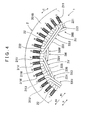
- FIG. 4 is a pattern diagram showing the formation of the first side coil end conductor portion 33 on the outside of an end surface 201B of the stator 1 on the axial first side L2.
- the coil end connecting portions 321, 322 of the second side coil end conductor portion 32 according to the first embodiment are formed from an axial rectilinear portion 321 formed parallel to the slot conductor portion 31 as a continuation of the slot conductor portion 31, and an outwardly bent portion 322 that is bent toward the radial outer side R2 relative to the axial rectilinear portion 321.
- the second side transition wire portion 323 according to the first embodiment is formed from a coil end curved portion 323 that connects the outwardly bent portions 322 to each other in an arc shape extending in the circumferential direction C of the stator core 2.
- the coil conductor 3 of each phase is formed by raising the two slot conductor portions 31 of the same phase disposed in adjacent slots 21 of the same phase from the second side coil end conductor portion 32 disposed on the outside of the end surface 201 A of the axial second side L1 of the stator core 2 to form the axial rectilinear portion 321, then bending the slot conductor portions 31 toward the radial outer side R2 relative to the axial rectilinear portion 321 to form the outwardly bent portion 322, and then connecting the outwardly bent portions 322 to each other in an arc shape extending in the circumferential direction C of the stator core 2 to form the coil end curved portion 323.
- the coil end curved portions 323 of the second side coil end conductor portions 32 of the same phase are disposed in the circumferential direction C in an overlapping state such that two coil end curved portions 323 are aligned in the axial direction L of the stator core 2.
- the coil end connecting portions 331, 332 of the first side coil end conductor portion 33 according to the first embodiment are formed from an axial rectilinear portion 331 formed parallel to the slot conductor portion 31 as a continuation of the slot conductor portion 31, and an inwardly bent portion 332 that is bent toward the radial inner side R1 relative to the axial rectilinear portion 331.
- the first side transition wire portion 333 according to the first embodiment is formed from a coil end rectilinear portion 333 that connects the inwardly bent portions 332 to each other in a rectilinear shape.
- the coil conductor 3 of each phase is formed by raising the two slot conductor portions 31 of the same phase disposed in adjacent slots 21 of the same phase from the first side coil end conductor portion 33 disposed on the outside of the end surface 201B of the axial first side L2 of the stator core 2 to form the axial rectilinear portion 331, then bending the slot conductor portions 31 toward the radial inner side R1 relative to the axial rectilinear portion 331 to form the inwardly bent portion 332, and then connecting the inwardly bent portions 332 to each other in a rectilinear shape in a perpendicular direction to the axial direction L of the stator core 2 to form the coil end rectilinear portion 333.
- the coil end rectilinear portions (first side transition wire portions) 333 of the first side coil end conductor portions 33 are disposed in a perpendicular direction to the axial direction L in an overlapping state such that two coil end rectilinear portions 333 are aligned in the radial direction R of the stator core 2.
- the first side coil end conductor portion 33 may be constituted using a curved (arc-shaped) coil end curved portion 333Z that extends in the circumferential direction C of the stator core 2 instead of the coil end rectilinear portion (transition wire portion) 333.
- a circular inner peripheral side end portion is formed by the coil end curved portions 323 of the three phases in the second side coil end conductor portions 32 of the coil conductors 3U, 3V, 3W of the three phases.
- a polygonal inner peripheral side end portion is formed by the coil end rectilinear portions (first side transition wire portions) 333 of the three phases in the first side coil end conductor portions 33 of the coil conductors 3U, 3V, 3W of the three phases.
- the coil conductors 3 of the respective phases have an identical sectional area in the slot conductor portion 31 and the coil end conductor portion 32.
- the coil conductors 3U. 3V, 3W of the U phase, the V phase and the W phase are disposed in eight turns (eight times around the circumference) when the two adjacent slots 21 of each phase are combined.
- a second side coil end portion 30A is formed on the outside of the end surface 201A of the axial second side L1 of the stator core 2 in the radial direction R of the stator core 2 by disposing two second side coil end conductor portions 32 of the same phase, which are aligned in the axial direction L of the stator core 2, between two second side coil end conductor portions 32 of the same phase aligned in the axial direction L of the stator core 2.
- FIG 3 shows a state in which two V phase second side coil end conductor portions 32V aligned in the axial direction L of the stator core 2 are disposed between two U phase second side coil end conductor portions 32U aligned in the axial direction L of the stator core 2 in the radial direction R of the stator core 2 within the second side coil end portion 30A.
- a first side coil end portion 30B is formed on the outside of the end surface 201B of the axial first side L2 of the stator core 2 in the axial direction L of the stator core 2 by disposing two first side coil end conductor portions 33 of another phase, which are aligned in the radial direction R of the stator core 2, between two first side coil end conductor portions 33 of another phase aligned in the radial direction R of the stator core 2.
- FIG 3 shows a state in which two V phase first side coil end conductor portions 33V aligned in the radial direction R of the stator core 2 are disposed between two U phase first side coil end conductor portions 33U aligned in the radial direction R of the stator core 2 in the axial direction L of the stator core 2 within the first side coil end portion 30B.
- the coil conductors 3 of the respective phases are formed to travel around the stator core 2 twice in the circumferential direction C, and as shown in FIGS. 2 and 6 , the coil conductors 3 of the respective phases are disposed so as to overlap in a plurality of stages in the radial direction R of the stator core 2.
- conductor end portions 302 of the coil conductors 3 of the same phase are joined to each other in the second side transition wire portion 323 of the second side coil end conductor portion 32 to form joint parts 327 that overlap in the radial direction R.
- the wave-wound coil conductors 3 of each phase that travel around the stator core 2 twice in the circumferential direction C are formed by disposing the slot conductor portions 31 in adjacent slots 21 of the same phase. More specifically, the coil conductors 3 of the same phase, in which the slot conductor portions 31 are disposed in adjacent slots 21 of the same phase, are constituted by a single continuous electric wire 301 that travels around the stator core 2 once.
- the coil conductors 3U, 3V, 3W of the three phases are formed by joining the wave-wound coil conductors 3 that travel twice around the stator core 2 continuously in the circumferential direction C in the respective conductor end portions 302 so as to be disposed in the stator core 2 in a number of rounds that is an integral multiple of 2 (8 in this example).
- the wave-wound coil conductors 3 of the respective phases that travel around the stator core 2 twice the number of joint locations on the coil conductors 3U, 3V, 3W of the three phases disposed in the stator core 2 can be approximately halved in comparison with a case in which wave-wound coil conductors that travel around a stator core once are joined by welding or the like.
- the joint parts 327 of the respective conductor end portions 302 of the coil conductors 3 are indicated by two-dot chain lines.
- the V phase coil end curved portion 323V is formed in a bent shape having an inside part 324 disposed perpendicular to the axial direction L of the stator core 2, an outside part 325 disposed perpendicular to the axial direction of the stator core 2 but further toward the axial outer side than the inside part 324, and a connecting part 326 that connects the outside part 325 to the inside part 324.
- the U phase coil end curved portion 323U is disposed to overlap the inside part 324 on the axial outer side
- the W phase coil end curved portion 323W is disposed to overlap the outside part 325 on the axial inner side.
- the coil end curved portions 323 of the second side coil end conductor portions 32 of the three phases are disposed discretely at substantially equal intervals in the circumferential direction C within a two-phase radial width range.
- the second side coil end portion 30A is formed by repeating a condition in which the U phase coil end curved portion 323U and the W phase coil end curved portion 323W overlap the V phase coil end curved portion 323V on the radial outer side R2 and the radial inner side R1, respectively, a plurality of times (four times in the first embodiment).
- the first side transition wire portions (coil end rectilinear portions) 333U, 333W of the U phase and W phase coil conductors 3U, 3W from among the coil conductors 3 of the three phases are provided in offset positions from each other in the axial direction L.
- the first side transition wire portion 333V of the remaining V phase coil conductor 3V is bent in the axial direction L between the end portions in the circumferential direction C of the first side transition wire portions 333U, 333W of the U phase and W phase coil conductors 3U, 3W so as to overlap the first side transition wire portions 333U, 333W of the U phase and W phase coil conductors 3U, 3W in the axial direction L.
- the V phase coil end rectilinear portion 333V is formed in a bent shape having an inside part 334 disposed perpendicular to the axial direction L of the stator core 2, an outside part 335 disposed perpendicular to the axial direction of the stator core 2 but further toward the axial outer side than the inside part 334, and a connecting part 336 that connects the outside part 335 to the inside part 334.
- the U phase coil end rectilinear portion 333U is disposed to overlap the inside part 334 on the axial outer side
- the W phase coil end rectilinear portion 333W is disposed to overlap the outside part 335 on the axial inner side.
- the coil end rectilinear portions 333 of the first side coil end conductor portions 33 of the three phases are disposed discretely at substantially equal intervals in the circumferential direction C within a two-phase axial width range.
- the first side coil end portion 30B is formed by repeating a condition in which the U phase coil end rectilinear portion 333U and the W phase coil end rectilinear portion 333W overlap the V phase coil end rectilinear portion 333V on the axial outer side and the axial inner side, respectively, a plurality of times (four times in the first embodiment).
- the slot conductor portions 31 of each phase are disposed in the slots 21 of each phase so as to overlap in the radial direction R.
- the first side transition wire portion 333 which is connected to an outermost peripheral side slot conductor portion 31 disposed on an outermost peripheral side in the radial direction R, from among the slot conductor portions 31 disposed in the slots 21 of each phase so as to overlap in the radial direction R of the stator core 2, is disposed farthest away from the stator core 2 in the axial direction L.
- first side transition wire portion 333 connected to the slot conductor portion 31 that overlaps an inner peripheral side of the outermost peripheral side slot conductor portion 31 is disposed on the stator core 2 side (the inner side of the axial direction L) so as to overlap the first side transition wire portion 333 connected to the outermost peripheral side slot conductor portion 31 in the axial direction L.
- a radius of curvature of the inwardly bent portion 332 of the first side coil end conductor portion 33 connected to the inner peripheral side slot conductor portion 31 disposed to overlap the inner peripheral side of the outermost peripheral side slot conductor portion 31 is smaller than a radius of curvature of the inwardly bent portion 332 of the first side coil end conductor portion 33 connected to the outermost peripheral side slot conductor portion 31 positioned on the outermost peripheral side of the slots 21 of each phase.
- the coil end rectilinear portion 333 of the first side coil end conductor portion 33 connected to the inner peripheral side slot conductor portion 31 is disposed on the inside of the coil end rectilinear portion 333 of the first side coil end conductor portion 33 connected to the outermost peripheral side slot conductor portion 31 in the axial direction L of the stator core 2.
- a core extension forming portion 23 for disposing the outwardly bent portion 322 of the second side coil end conductor portion 32 is formed as an extension of the end surface 201A of the axial second side L1 of the stator core 2.
- the core extension forming portion 23 may be constructed by forming an inclined surface 231 for disposing the outwardly bent portion 322 on the inner peripheral side.
- an inter-phase insulating paper 42 may be disposed between the coil end rectilinear portions 333 of the first side coil end conductor portions 33 of the three phases.
- the inter-phase insulating paper 42 may be disposed between the coil end rectilinear portions 333 of different phases disposed in series in the axial direction L of the stator core 2 by disposing identically shaped papers (papers having a standardized shape) in series in the axial direction L.
- stator 1 Next, a method of manufacturing the above stator 1 will be described.
- the coil conductor 3 of each phase is formed in a wave-wound shape that travels around the stator core 2 in the circumferential direction C twice using the continuous single electric wire 301.
- the coil conductors 3U, 3V, 3W of the three phases are molded such that the first side transition wire portions 333 of the respective phases, which extend in the circumferential direction C in the first side coil end conductor portion 33, are disposed further toward the radial inner side R1 than the inner peripheral end surface 221 of the tooth 22, and the coil conductors 3U, 3V, 3W of the three phases are molded in different shapes such that the first side transition wire portion 333 of each phase is provided in a different position to the first side transition wire portions 333 of the other phases.
- first side transition wire portions (coil end rectilinear portions) 333U, 333W of the U phase and W phase coil conductors 3U, 3W, from among the coil conductors 3U, 3V, 3W of the three phases, are molded so as to be offset from each other in the axial direction L, and the first side transition wire portion 333V of the remaining V phase coil conductor 3V is bent in the axial direction L between end portions in the circumferential direction C of the first side transition wire portions 333U, 333W of the U phase and W phase coil conductors 3U, 3W so as to overlap the first side transition wire portions 333U, 333W of the U phase and W phase coil conductors 3U, 3W in the axial direction L.
- the coil conductors 3U, 3V, 3W of the three phases are combined to form a coil conductor assembly 35.
- a jig or the like may be used to ensure that the three-dimensional shape of the coil conductor assembly 35 does not collapse.
- the coil conductor assembly 35 is formed by combining all of the coil conductors 3U, 3V, 3W of the three phases to be disposed in the stator core 2.
- a slot insulating paper 41 may be disposed in the respective slot conductor portions 31 of the coil conductor assembly 35 formed by combining the coil conductors 3U, 3V, 3W of the three phases.
- the coil conductor assembly 35 is inserted into the stator core 2 from the first side coil end conductor portion 33 side.
- the entire first side coil end conductor portion 33 is positioned further toward the radial inner side R1 than the outer peripheral end surfaces 21 of all of the slots 21, and therefore the coil conductor assembly 35 can be inserted in the stator core 2 from the first side coil end conductor portion 33 side easily.
- the coil conductor assembly 35 can be inserted into the plurality of slots 21 in the stator core 2 simultaneously from the axial end surface of the stator core 2 in the axial direction L of the stator core 2.
- the stator 1 can be manufactured by inserting the coil conductor assembly 35 described above into the plurality of slots 21 in the stator core 2 simultaneously (at once), starting with the first side coil end conductor portion 33 side, along the axial direction L of the stator core 2 from the end surface 201B on the axial first side L2 of the stator core 2.
- the stator core 2 is held by a holding jig 51 and the coil conductor assembly 35 is held by an insertion jig 52 such that, by inserting the insertion jig 52 into the holding jig 51, the coil conductor assembly 35 can be inserted into the stator core 2.
- the slot insulating paper 41 may be disposed ion each slot 21 of the stator core 2. In this case, as shown in FIG.
- an insulating paper holding jig 53 for ensuring that the slot insulating paper 41 does not fall out of the stator core 2 may be used on the inner peripheral side of the stator core 2 held by the holding jig 51.
- the insulating paper holding jig 53 can be removed gradually from the part of the stator core 2 held by the holding jig 51 into which the insertion jig 52 holding the coil conductor assembly 35 is inserted. Hence, when the coil conductor assembly 35 is inserted into the stator core 2, the slot insulating paper 41 can be prevented from falling out.
- the stator 1 according to the first embodiment by manipulating the shape of the first side coil end conductor portion 33, the coil conductors 3U, 3V, 3W of the three phases can be inserted easily into the stator core 2 and the need for further molding of the coil conductors after insertion into the stator core 2 can be eliminated.
- the second side coil end conductor portion 32 is shaped, similarly to that of the related art, to be bent toward the outer peripheral side of the stator core 2, whereby the entire second side coil end conductor portion 32 is positioned further toward the radial outer side R2 than the inner peripheral end surface 221 of the tooth 22.
- the rotor when a rotor is inserted into the stator 1 formed by inserting the coil conductors 3U, 3V, 3W of the three phases into the stator core 2, the rotor can be inserted from the axial second side L1 of the stator core 2 on which the second side coil end conductor portion 32 is positioned. As a result, the rotor can be disposed relative to the stator 1 easily.
- the first side coil end conductor portion 33 is shaped to be bent toward the inner peripheral side of the stator core 2 such that the entire first side coil end conductor portion 33 is positioned further toward the radial inner side R1 than the outer peripheral end surface 211 of the slot 21.
- the stator 1 according to the first embodiment can be manufactured without performing molding processing such as bending molding and compression molding on the first side coil end portion 30B after insertion into the stator core 2, with substantially no further processing after insertion.
- molding processing such as bending molding and compression molding
- an insulating film provided on the surface of the conductor portion constituting the coil conductor 3 suffers substantially no breakage or deterioration. Therefore, the quality of the stator 1 according to the first embodiment can be improved.
- the coil conductors 3U, 3V, 3W of the three phases can be assembled in advance prior to insertion into the stator core 2 such that all of the coil conductors 3U, 3V, 3W of the three phases can be inserted into the stator core 2 simultaneously.
- the coil conductors 3U, 3V, 3W of the three phases can be inserted into the stator core 2 very easily.
- the coil conductors 3 may be inserted into the stator core 2 in predetermined units (numbers) and then joined by welding or the like in a state where the coil conductors 3 are disposed in the stator core 2.
- the coil end rectilinear portion 333 in the first side coil end conductor portion 33 of the coil conductors 3U, 3V, 3W of the three phases is disposed to overlap the coil end rectilinear portion 333 of the first side coil end conductor portion 33 in a coil conductor 3 of another phase in the axial direction L of the stator core 2.
- the first side coil end conductor portion 33 can be prevented from projecting toward the radial inner side R1, thereby preventing deformation of the first side coil end conductor portion 33 due to vibration.
- the distance between the first side coil end conductor portion 33 and the rotor can be reduced, thereby making the first side coil end conductor portion 33 compact.
- FIG. 15 shows a conventional stator 9 formed by bending coil end conductor portions 92 on both sides toward the outer peripheral side of the stator core 2.
- the coil conductors 3U, 3V, 3W of the three phases can be disposed in the stator core 2 easily, the quality of the coil conductors 3U, 3V, 3W of the three phases can be maintained at a high level, and the size of the stator 1 can be reduced.
- FIGS. 16 to 34 A second embodiment relating to another stator according to the present invention will now be described with reference to FIGS. 16 to 34 .
- the reference numerals of the respective terms (constitutional components) in FIGS. 16 to 34 of the second embodiment are applied separately to those in FIGS. 1 to 15 of the first embodiment. Hence, some of the reference numerals may be the same as those used in the first embodiment but indicate different terms (constitutional components). This applies likewise to a third embodiment to be described below.
- a stator 1 is formed by disposing coils 3U, 3V, 3W of three phases, namely a U phase, a V phase, and a W phase, in a distributed winding form in a plurality of slots 21 formed along an axial direction L of a stator core 2.
- a plurality of coil conductors 4 of the same phase are disposed in series in a radial direction R of the stator core 2 in slots 21 of the same phase.
- the coils 3U, 3V, 3W of the three phases are formed such that in a second side coil end portion 30A projecting from an axial first end surface 201A of the stator core 2, the plurality of coil conductors 4 of the same phase are disposed in series in the radial direction R or the axial direction L of the stator core 2, and in a first side coil end portion 30B projecting from an axial second end surface 201B of the stator core 2, the plurality of coil conductors 4 of the same phase are bent toward a radial inner peripheral side R1 of the stator core 2 and disposed in series in the radial direction R of the stator core 2.
- the stator 1 according to the second embodiment will be described in detail below with reference to FIGS. 16 to 34 .
- the stator 1 according to the second embodiment is used in a three-phase alternating current motor for a hybrid car, an electric automobile, or the like, and is formed by incorporating the coils 3U, 3V, 3W of the three phases, namely the U phase, the V phase, and the W phase, in the stator core 2.
- the coils 3U, 3V, 3W of the three phases are each constituted by an angular wire conductor 301 in which an insulating film made of insulating resin or the like is formed around the entire circumference of a conductor portion (conductor base material) made of copper or the like, and the angular wire conductor 301 has a substantially square eross-section.
- the coils 3U, 3V, 3W of the three phases according to the second embodiment are formed in a wave-wound shape in which the coils 3U, 3V, 3W of the three phases are positioned alternately in a second side coil end portion 30A and a first side coil end portion 30B from the slot 21 and travel around the stator core 2 in a circumferential direction C.
- the coils 3U, 3V, 3W of the three phases according to the second embodiment are formed in a wave-wound shape using two of the coil conductors 4 disposed in the same slot 21 as a set.
- the two coil conductors 4 are molded by causing a single continuous angular wire conductor 301 to travel around the stator core 2 twice in the circumferential direction C.
- the coils 3U, 3V, 3W of the three phases are constituted by a slot conductor portion 31 disposed in the slot 21, and a coil end conductor portion 32 that projects from the axial end surface 201 of the stator core 2 (i.e. that is disposed on the outside of the slot 21).
- the coil end conductor portion 32 positioned in the second side coil end portion 30A is constituted by a bent angular conductor portion 321 that is connected to the slot conductor portion 31 and bent in the circumferential direction C so as to stand upright from the axial first end surface 201A of the stator core 2, and a circumferential conductor portion (transition wire portion) 322 that connects the bent angular conductor portions 321 connected to respective slot conductor portions 31 to each other and is disposed in the circumferential direction C of the stator core 2.
- the coil end conductor portion 32 positioned in the first side coil end portion 30B is constituted by a bent angular conductor portion 321 that is connected to the slot conductor portion 31 and bent toward the radial inner peripheral side R1 so as to stand upright from the axial second end surface 201B of the stator core 2, and a circumferential conductor portion (transition wire portion) 322 that connects the bent angular conductor portions 321 connected to respective slot conductor portions 31 to each other and is disposed in the circumferential direction C of the stator core 2.
- the circumferential conductor portion 322 is molded into an arc shape extending in the circumferential direction C of the stator core 2 in the second side coil end portion 30A and first side coil end portion 30B.
- the circumferential conductor portion 322 may also be molded into a rectilinear shape in the first side coil end portion 30B.
- the circumferential conductor portion 322 of each phase is formed with a portion in which the U phase circumferential conductor portion 322 and the V phase circumferential conductor portion 322 are disposed to overlap in the radial direction R of the stator core 2, a portion in which the U phase circumferential conductor portion 322 and the W phase circumferential conductor portion 322 are disposed to overlap in the radial direction R of the stator core 2, and a portion in which the V phase circumferential conductor portion 322 and the W phase circumferential conductor portion 322 are disposed to overlap in the radial direction R of the stator core 2.
- two adjacent U phase slots 21U, two adjacent V phase slots 21V, and two adjacent W phase slots 21 Ware formed repeatedly in that order in the stator core 2.
- the two adjacent slots 21 of the same phase are formed in eight locations in the circumferential direction C of the stator core 2. Further, sixteen slots 21 of each phase are formed, giving a total of 48 slots 21 of the three phases.
- the coils 3U, 3V, 3W of the three phases according to the second embodiment use pairs of coil conductors 4 disposed within the same slot 21 in series in the radial direction R, and two pairs of coil conductors 4 are disposed in the same slot 21 of the stator core 2 in series in the radial direction R. Hence, four coil conductors 4 of the same phase are disposed in each slot 21 in series in the radial direction R. Further, four coil conductors 4 are disposed similarly in adjacent slots 21 of the same phase in series in the radial direction R.
- the pairs of coil conductors 4 positioned on the inner side of the axial direction L of the stator core 2 in the second side coil end portion 30A are positioned on the radial inner peripheral side R1 of the stator core 2 in the first side coil end portion 30B.
- the pairs of coil conductors 4 positioned on the outer side of the axial direction L of the stator core 2 in the second side coil end portion 30A are positioned on the radial outer peripheral side R2 of the stator core 2 in the first side coil end portion 30B.
- the coils 3U, 3V, 3W of the three phases are formed by disposing pairs of coil conductors 4 of the same phase in adjacent slots 21 of the same phase in series in the radial direction R of the stator core 2. Further, in adjacent slots 21 of the same phase, pairs of coil conductors 4 of a different phase are disposed in series on the radial inner peripheral side R1 of the pairs of coil conductors 4 of the same phase. Further, in the second side coil end portion 30A, the coils 3U, 3V, 3W of the three phases are formed by disposing pairs of coil conductors 4 of the same phase disposed in a slot 21 of the same phase in series in the axial direction L of the stator core 2.
- pairs of coil conductors 4 of the same phase disposed in adjacent slots 21 of the same phase are disposed in four rows in the axial direction L of the stator core 2.
- the pairs of coil conductors 4 of the same phase disposed in adjacent slots 21 of the same phase may be formed by molding a single continuous angular wire conductor 301 integrally so as to travel around the stator core 2 four times in the circumferential direction C.
- the coils 3U, 3V, 3W of the three phases are formed by disposing two coil conductors 4 of the same phase disposed in one of two adjacent slots 21 of the same phase and two coil conductors 4 of the same phase disposed in the other slot 21 of the two adjacent slots 21 of the same phase in four rows in the radial direction R of the stator core 2.
- FIG. 19 in the first side coil end portion 30B, the coils 3U, 3V, 3W of the three phases are formed by disposing two coil conductors 4 of the same phase disposed in one of two adjacent slots 21 of the same phase and two coil conductors 4 of the same phase disposed in the other slot 21 of the two adjacent slots 21 of the same phase in four rows in the radial direction R of the stator core 2.
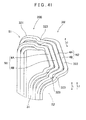
- the two coil conductors 4 of the same phase disposed in series in the slot 21 of the same phase in the radial direction R of the stator core 2 are formed by bending a first coil conductor 4A toward the radial inner peripheral side R1 of the stator core 2 in a perpendicular state relative to the axial direction L of the stator core 2 and bending a second coil conductor 4B toward the radial inner peripheral side R1 of the stator core 2 so as to be offset from the axial direction L of the stator core 2 and disposed in series with the first coil conductor 4A in the radial direction R of the stator core 2.
- the coil conductors 4 are changed from the condition in which the coil conductors 4 are arranged in twos in the axial direction L of the stator core 2 in the bent angular conductor portion 321 to the condition in which the coil conductors 4 are arranged in twos in the radial direction R.
- the coil conductors 4 constituting the coils 3U, 3V, 3W of the three phases are disposed to extend from two adjacent slots 21 of the same phase (a first slot conductor group S1 to be described below) to two slots 21 of the same phase (a second slot conductor group S2 to be described below) adjacent to the two slots 21 of the same phase in the circumferential direction.
- the coil conductors 4 of the V phase coil 3V are offset in the axial direction L of the stator core 2 in a central part of the stator core 2 in the circumferential direction C so as to include an inside pan 325 positioned on a circumferential first side C1 of the stator core 2 and an axial direction inner side L1, and an outside part 326 positioned on a circumferential second side C2 of the stator core 2 and an axial outer side L2.
- the coil conductors 4 of the U phase coil 3U are disposed to overlap the inside part 325 of the coil conductors 4 of the V phase coil 3V on the axial outer side L2 of the stator core 2.
- the coil conductors 4 of the W phase coil 3W are disposed to overlap the outside part 326 of the coil conductors 4 of the V phase coil 3V on the axial inner side L1 of the stator core 2.
- the pairs of coil conductors 4 of the coils 3U, 3V, 3W of each phase disposed in the slots 21 of each phase on the outside of the radial direction R are disposed discretely at substantially equal intervals in the circumferential direction C within a two-phase axial width range.
- the pairs of coil conductors 4 of the coils 3U, 3V, 3 W of each phase disposed in the slots 21 of each phase on the inside of the radial direction R are disposed discretely at substantially equal intervals in the circumferential direction C within a two-phase axial width range so as to overlap the pairs of coil conductors 4 disposed on the outside of the radial direction R on the axial inner side L1.
- the coils 3U, 3V, 3W of the three phases according to the second embodiment may be formed parallel to the axial direction L and molded into a wave-wound shape that travels around the circumferential direction C, whereupon the first side coil end portion 30B is bent toward the inner peripheral side of the circumferential direction C. Further, conductor end portions of the two coil conductors 4 of the same phase are joined at a coil end conductor portion 32 positioned in the second side coil end portion 30A while overlapping in the radial direction R (not shown).
- any two adjacent slots 21 of the same phase constitute a first slot group S1
- two adjacent slots 21 of the same phase disposed adjacent to the two slots 21 of the same phase constituting the first slot group S1 on one side in the circumferential direction C constitute a second slot group S2.
- the slot 21 positioned on the inner side in the circumferential direction C constitutes an inside sloth 21A
- the slot 21 positioned on the outer side in the circumferential direction C constitutes an outside slot 21B.
- FIGS. 20 to 23 show the manner in which the U phase coil 3U is formed.
- a first pair of U phase coil conductors 4 (N1) disposed in the inside slot 21 A of the first slot group S1 and the inside slot 21A of the second slot group S2 are provided in the slot 21 in series in the radial direction R such that the first coil conductor 4A positioned on the radial outer peripheral side R2 of the slot 21 is also positioned on the radial outer peripheral side R2 in the first side coil end portion 30B, while the second coil conductor 4B positioned on the radial inner peripheral side R1 of the slot 21 is positioned on the radial inner peripheral side R1 of the first coil conductor 4A in the first side coil end portion 30B.
- a second pair of U phase coil conductors 4 (N2) disposed in the outside slot 21B of the first slot group S1 and the outside slot 21 B of the second slot group S2 are provided in the slot 21 in series in the radial direction R such that the first coil conductor 4A positioned on the radial outer peripheral side R2 of the slot 21 is also positioned on the radial outer peripheral side R2 in the first side coil end portion 30B, while the second coil conductor 4B positioned on the radial inner peripheral side R1 of the slot 21 is positioned on the radial inner peripheral side R1 of the first coil conductor 4A in the first side coil end portion 30B.
- the second pair of U phase coil conductors 4 (N2) is disposed in series on the radial inner peripheral side R1 of the first pair of U phase coil conductors 4 (N1).
- a third pair of U phase coil conductors 4 (N3) disposed in the inside slot 21A of the first slot group S1 and the inside slot 21A of the second slot group S2 so as to overlap the first pair of U phase coil conductors 4 (N1) on the radial inner peripheral side R1 in the inside slot 21 A are provided in the slot 21 in series in the radial direction R such that the first coil conductor 4A positioned on the radial outer peripheral side R2 of the slot 21 is also positioned on the radial outer peripheral side R2 in the first side coil end portion 30B, while the second coil conductor 4B positioned on the radial inner peripheral side R1 of the slot 21 is positioned on the radial inner peripheral side R1 of the first coil conductors 4A in the first side coil end portion 30B.
- a fourth pair of U phase coil conductors 4 (N4) disposed in the outside slot 21B of the first slot group S1 and the outside slot 21B of the second slot group S2 so as to overlap the second pair of U phase coil conductors 4 (N2) on the radial inner peripheral side R1 of the outside slot 21B are provided in the slot 21 in series in the radial direction R such that the first coil conductor 4A positioned on the radial outer peripheral side R2 of the slot 21 is also positioned on the radial outer peripheral side R2 in the first side coil end portion 30B, while the second coil conductor 4B positioned on the radial inner peripheral side R1 of the slot 21 is positioned on the radial inner peripheral side R1 of the first coil conductor 4A in the first side coil end portion 30B.
- the fourth pair of U phase coil conductors 4 (N4) is disposed in series on the radial inner peripheral side R1 of the third pair of U phase coil conductors 4 (N3).
- the first coil conductor 4A positioned on the radial outer peripheral side R2 of the U phase slot 21 U in the first and second pairs of U phase coil conductors 4 (N1, N2) is offset to the inside in the circumferential direction C in the radial conductor portion 323 provided between the bent angular conductor portion 321 and the circumferential conductor portion 322, while the second coil conductor 4B positioned on the radial inner peripheral side R1 of the U phase slot 2 1 U is offset to the outside in the axial direction L in the radial conductor portion 323 provided between the bent angular conductor portion 321 and the circumferential conductor portion 322.
- the respective circumferential conductor portions 322 are aligned in the radial direction R.
- the respective coil conductors 4 are offset such that the respective circumferential conductor portions 322 are aligned in the radial direction R.
- FIGS. 24 to 27 show the manner in which the V phase coil 3V is formed.
- a first pair of V phase coil conductors 4 (N1) disposed in the inside slot 21A of the first slot group S1 and the inside slot 21A of the second slot group S2 are provided in the slot 21 in series in the radial direction R such that the first coil conductor 4A positioned on the radial outer peripheral side R2 of the slot 21 is also positioned on the radial outer peripheral side R2 in the first side coil end portion 30B, while the second coil conductor 4B positioned on the radial inner peripheral side R1 of the slot 21 is positioned on the radial inner peripheral side R1 of the first coil conductor 4A in the first side coil end portion 30B.
- a second pair of V phase coil conductors 4 (N2) disposed in the outside slot 21B of the first slot group S1 and the outside slot 21B of the second slot group S2 are provided in the slot 21 in series in the radial direction R such that the first coil conductor 4A positioned on the radial outer peripheral side R2 of the slot 21 is also positioned on the radial outer peripheral side R2 in the first side coil end portion 30B, while the second coil conductor 4B positioned on the radial inner peripheral side R1 of the slot 21 is positioned on the radial inner peripheral side R1 of the first coil conductor 4A in the first side coil end portion 30B.
- the second pair of V phase coil conductors 4 (N2) is disposed in series on the radial inner peripheral side R1 of the first pair of V phase coil conductors 4 (N1).
- a third pair of V phase coil conductors 4 (N3) disposed in the inside slot 21 A of the first slot group S1 and the inside slot 21 A of the second slot group S2 so as to overlap the first pair of V phase coil conductors 4 (N1) on the radial inner peripheral side R1 of the inside slot 21A are provided in the slot 21 in series in the radial direction R such that the first coil conductor 4A positioned on the radial outer peripheral side R2 of the slot 21 is also positioned on the radial outer peripheral side R2 in the first side coil end portion 30B, while the second coil conductor 4B positioned on the radial inner peripheral side R1 of the slot 21 is positioned on the radial inner peripheral side R1 of the first coil conductor 4A in the first side coil end portion 30B.
- a fourth pair of V phase coil conductors 4 (N4) disposed in the outside slot 21B of the first slot group S1 and the outside slot 21B of the second slot group S2 so as to overlap the second pair of V phase coil conductors 4 (N2) on the radial inner peripheral side R1 of the outside slot 21B are provided in the slot 21 in series in the radial direction R such that the first coil conductor 4A positioned on the radial outer peripheral side R2 of the slot 21 is also positioned on the radial outer peripheral side R2 in the first side coil end portion 30B, while the second coil conductor 4B positioned on the radial inner peripheral side R1 of the slot 21 is positioned on the radial inner peripheral side R1 of the first coil conductor 4A in the first side coil end portion 30B.
- the fourth pair of V phase coil conductors 4 (N4) is disposed in series on the radial inner peripheral side R1 of the third pair of V phase coil conductors 4 (N3).
- the first coil conductor 4A positioned on the radial outer peripheral side R2 of the V phase slot 21V in a part of the first and second pairs of V phase coil conductors 4 (N1, N2) on a circumferential first side C1 is offset to the axial inner side L1 in the radial conductor portion 323 provided between the bent angular conductor portion 321 and the inside part 325 of the circumferential conductor portion 322, while the second coil conductor 4B positioned on the radial inner peripheral side R1 of the V phase slot 21V is offset to the outside of the circumferential direction C in the radial conductor portion 323 provided between the bent angular conductor portion 321 and the inside part 325 of the circumferential conductor portion 322.
- the respective circumferential conductor portions 322 are aligned in the radial direction R.
- first coil conductor 4A positioned on the radial outer peripheral side R2 of the V phase slot 21 V in a part of the first and second pairs of V phase coil conductors 4 (N1, N2) on a circumferential second side C2 is offset to the axial inner side L1 in the radial conductor portion 323 provided between the bent angular conductor portion 321 and the inside part 325 of the circumferential conductor portion 322, while the second coil conductor 4B positioned on the radial inner peripheral side R1 of the V phase slot 21V is offset to the outside of the circumferential direction C in the radial conductor portion 323 provided between the bent angular conductor portion 321 and the inside part 325 of the circumferential conductor portion 322.
- the respective circumferential conductor portions 322 are aligned in the radial direction R.
- the respective coil conductors 4 are offset such that the respective circumferential conductor portions 322 are aligned in the radial direction R.
- the respective coil conductors 4 are offset such that the respective circumferential conductor portions 322 are aligned in the radial direction R.
- FIGS. 28 to 31 show the manner in which the W phase coil 3W is formed.
- a first pair of W phase coil conductors 4 (N1) disposed in the inside slot 2 1 A of the first slot group S1 and the inside slot 21A of the second slot group S2 are provided in the slot 21 in series in the radial direction R such that the first coil conductor 4A positioned on the radial outer peripheral side R2 of the slot 21 is positioned on the radial inner peripheral side R1 in the first side coil end portion 30B, while the second coil conductor 4B positioned on the radial inner peripheral side R1 of the slot 21 is positioned on the radial outer peripheral side R2 of the first coil conductor 4A in the first side coil end portion 30B.
- a second pair of W phase coil conductors 4 (N2) disposed in the outside slot 21B of the first slot group S1 and the outside slot 21 B of the second slot group S2 are provided in the slot 21 in series in the radial direction R such that the first coil conductor 4A positioned on the radial outer peripheral side R2 of the slot 21 is positioned on the radial inner peripheral side R1 in the first side coil end portion 30B, while the second coil conductor 4B positioned on the radial inner peripheral side R1 of the slot 21 is positioned on the radial outer peripheral side R2 of the first coil conductor 4A in the first side coil end portion 30B.
- the second pair of W phase coil conductors 4 (N2) is disposed in series on the radial inner peripheral side R1 of the first pair of W phase coil conductors 4 (N1).
- a third pair of W phase coil conductors 4 (N3) disposed in the inside slot 21A of the first slot group S1 and the inside slot 21 A of the second slot group S2 so as to overlap the first pair of W phase coil conductors 4 (N1) on the radial inner peripheral side R1 of the inside slot 21A are provided in the slot 21 in series in the radial direction R such that the first coil conductor 4A positioned on the radial outer peripheral side R2 of the slot 21 is positioned on the radial inner peripheral side R1 in the first side coil end portion 30B, while the second coil conductor 4B positioned on the radial inner peripheral side R1 of the slot 21 is positioned on the radial outer peripheral side R2 of the first coil conductor 4A in the first side coil end portion 30B.
- a fourth pair of W phase coil conductors 4 (N4) disposed in the outside slot 21 B of the first slot group S1 and the outside slot 21 B of the second slot group S2 so as to overlap the second pair of W phase coil conductors 4 (N2) on the radial inner peripheral side R1 of the outside slot 21B are provided in the slot 21 in series in the radial direction R such that the first coil conductor 4A positioned on the radial outer peripheral side R2 of the slot 21 is positioned on the radial inner peripheral side R1 in the first side coil end portion 30B, while the second coil conductor 4B positioned on the radial inner peripheral side R1 of the slot 21 is positioned on the radial outer peripheral side R2 of the first coil conductor 4A in the first side coil end portion 30B.
- the fourth pair of W phase coil conductors 4 (N4) is disposed in series on the radial inner peripheral side R1 of the third pair of W phase coil conductors 4 (N3).
- the first coil conductor 4A positioned on the radial outer peripheral side R2 of the W phase slot 21 W in the first and second pairs of W phase coil conductors 4 ( N2 ) is offset to the axial inner side L1 in the radial conductor portion 323 provided between the bent angular conductor portion 321 and the circumferential conductor portion 322, while the second coil conductor 4B positioned on the radial inner peripheral side R1 of the W phase slot 21 W is offset to the inside of the circumferential direction C in the radial conductor portion 323 provided between the bent angular conductor portion 321 and the circumferential conductor portion 322.
- the respective circumferential conductor portions 322 are aligned in the radial direction R.
- the respective coil conductors 4 are offset such that the respective circumferential conductor portions 322 are aligned in the radial direction R.
- the first coil conductor 4A is positioned on the radial outer peripheral side R2 of the slot 21 and the second coil conductor 4B is positioned on the radial inner peripheral side R1 of the slot 21.
- the positions of the first coil conductor 4A and the second coil conductor 4B are opposite to the positions of the first coil conductor 4A and the second coil conductor 4B in the first side coil end portions 30B of the U phase and V phase coils 3U, 3V with respect to the radial inner peripheral side R1 or the radial outer peripheral side R2 of the circumferential conductor portion 322.
- the pair of coil conductors 4 in the radial conductor portion 323 are bent in an identical manner in the part on the circumferential first side C1, and in the W phase coil 3W and the V phase coil 3V, the pair of coil conductors 4 are bent in an identical manner in the part on the circumferential second side C2.
- the coils 3U, 3V, 3W of the three phases according to the second embodiment are formed into a coil assembly 5 by combining all of the coils disposed in the stator core 2. and this coil assembly, 5 is disposed at once in the stator core 2.
- FIG. 32 shows a state in which the third and fourth pairs of coil conductors 4 (N3, N4) of the V phase coil 3V is combined with the third and fourth pairs of coil conductors 4 (N3, N4) of the W phase coil 3W.
- the outside part 326 of the circumferential conductor portion 322 of the V phase coil 3V overlaps the axial outer side L2 relative to the part of the circumferential conductor portion 322 of the W phase coil 3 W on the circumferential first side C1.
- a recessed portion 329 for disposing the circumferential conductor portion 322 of the U phase coil 3U is formed on the axial outer side L2 of the circumferential second side C2 part of the circumferential conductor portion 322 of the W phase coil 3W and the inside part 325 of the circumferential conductor portion 322 of the V phase coil 3V.
- FIG. 33 shows a state in which, with respect to the third and fourth pairs of coil conductors 4 (N3, N4) constituting the coils 3U, 3V, 3W of the three phases, the circumferential conductor portion 322 of the U phase coil 3U is disposed in the recessed portion 329 formed on the axial outer side L2 of the circumferential second side C2 part of the circumferential conductor portion 322 of the W phase coil 3W and the inside part 325 of the circumferential conductor portion 322 of the V phase coil 3V. Further, FIG.
- the coil assembly 5 formed by combining all of the coils 3U, 3V, 3W of the three phases can be inserted into all of the slots 21 in the stator core 2 from the first side coil end portion 30B to form the stator 1.
- an assembly jig may be used to determine the positions of the coils 3U, 3V, 3W of the three phases.
- an insertion jig may be used to facilitate insertion of the coil assembly 5.
- the coils 3U, 3V, 3W of the three phases can be disposed relative to the stator core 2 easily and the need for further molding of the coils 3U, 3V, 3W of the three phases after the coils 3U, 3V, 3W are disposed in the stator core 2 can be eliminated.
- the second side coil end portion 30A is shaped by being bent toward the radial outer peripheral side R2 of the stator core 2 before being disposed in the stator core 2, whereby the entirety of the second side coil end portion 30A is positioned further toward the radial outer peripheral side R2 than an inner peripheral end surface 221 of a tooth 22 (a part positioned between the slots 21).
- the coil end conductor portion 32 positioned in the second side coil end portion 30A may be formed by being bent toward the radial outer peripheral side R2.
- the first side coil end portion 30B is shaped by being bent toward the radial inner peripheral side R1 of the stator core 2 before being disposed in the stator core 2 such that the entirety of the first side coil end portion 30B is positioned further toward the radial inner peripheral side R1 than an outer peripheral end surface 211 of the slot 21.
- the coils 3U, 3V, 3W of the three phases when the coils 3U, 3V, 3W of the three phases are inserted into the stator core 2, the coils 3U, 3V, 3W of the three phases can be inserted into the stator core 2 from the axial second end surface 201B side, on which the first side coil end portion 30B is positioned.
- the coils 3U, 3V, 3W of the three phases can be disposed in the stator core 2 easily.
- the coils 3U, 3V, 3W of the three phases are formed such that a plurality of coil conductors 4 of the same phase are disposed in series in the radial direction R of the stator core 2.
- the amount by which the first side coil end portion 30B projects from the axial end surface 201 of the stator core 2 can be reduced.
- the size of the coil end portion 30B positioned on the axial second end surface 201B side of the stator 1 can be reduced in the axial direction L.
- the second side coil end portion 30A and first side coil end portion 30B can be molded into a post-assembly shape in advance, prior to disposal in the stator core 2.
- the coil end portions 30A, 30B on both sides can be finished as a product without performing molding processing, such as bending molding and compression molding, with substantially no further processing after insertion.
- molding processing such as bending molding and compression molding
- an insulating film provided on the surface of the coil conductors 4 constituting the coils 3 suffers substantially no breakage or deterioration. Therefore, the quality of the stator 1 according to the second embodiment can be improved.
- the coils 3U, 3V, 3W of the three phases can be assembled in advance prior to insertion into the stator core 2 such that the all of the coils 3U, 3V, 3W of the three phases can be inserted into the stator core 2 simultaneously.
- the coils 3U, 3V, 3W of the three phases can be inserted into the stator core 2 very easily.
- the coils 3 may be inserted into the stator core 2 in predetermined units (numbers) and then joined by welding or the like when disposed in the stator core 2.
- the coils 3U, 3V, 3W of the three phases can be disposed in the stator core 2 easily, the quality of the coils 3U, 3V, 3W of the three phases can be maintained at a high level, and the size of the stator 1 can be reduced.
- a third embodiment differs from the second embodiment described above in the manner in which the pairs of coil conductors 4 constituting the coils 3U, 3V, 3W of the three phases are formed.
- the reference numerals of the respective terms (constitutional components) in FIGS. 35 to 44 of the third embodiment are applied separately from those in FIGS. 1 to 15 of the first embodiment but shared with FIGS. 16 to 34 of the second embodiment.
- pairs of coil conductors 4 are disposed to overlap in the radial direction R such that the second pair of coil conductors 4 (N2) disposed respectively in the outside slots 21B of the first slot group S1 and second slot group S2 is disposed to overlap the first pair of coil conductors 4 (N1) disposed respectively in the inside slots 21A of the first slot group S1 and second slot group S2 on the radial inner side L1.
- the fourth pair of coil conductors 4 (N4) disposed respectively in the outside slots 21B of the first slot group S1 and second slot group S2 is disposed to overlap the third pair of coil conductor 4 (N3) disposed respectively in the inside slots 21A of the first slot group S1 and second slot group S2 on the radial inner side L1.
- FIGS. 36 and 37 show the manner in which the U phase coil 3U of the third embodiment is formed.
- the first pair of U phase coil conductors 4 (N1) disposed in the inside slot 21A of the first slot group S1 and the inside slot 21A of the second slot group S2 is provided in the slot 21 in series in the radial direction R such that the first coil conductor 4A positioned on the radial outer peripheral side R2 of the slot 21 is also positioned on the radial outer peripheral side R2 in the first side coil end portion 30B, while the second coil conductor 4B positioned on the radial inner peripheral side R1 of the slot 21 is positioned on the radial inner peripheral side R1 of the first coil conductor 4A in the first side coil end portion 30B.
- the second pair of U phase coil conductors 4 (N2) disposed in the outside slot 21B of the first slot group S1 and the outside slot 21B of the second slot group S2 is provided in the slot 21 in series in the radial direction R such that the first coil conductor 4A positioned on the radial outer peripheral side R2 of the slot 21 is also positioned on the radial outer peripheral side R2 in the first side coil end portion 30B, while the second coil conductor 4B positioned on the radial inner peripheral side R1 of the slot 21 is positioned on the radial inner peripheral side R1 of the first coil conductor 4A in the first side coil end portion 30B. Further, in the first side coil end portion 30B, the second pair of U phase coil conductors 4 (N2) is disposed in series on the radial inner peripheral side R1 of the first pair of U phase coil conductors 4 (N1).
- the third pair of U phase coil conductors 4 (N3) disposed in the inside slot 21 A of the first slot group S1 and the inside slot 21A of the second slot group S2 so as to overlap the first pair of U phase coil conductors 4 (N1) on the radial inner peripheral side R1 of the inside slot 21A has a similar constitution to the first pair of coil conductors 4 (N1).
- the fourth pair of U phase coil conductors 4 (N4) disposed in the outside slot 21 B of the first slot group S1 and the outside slot 21 B of the second slot group S2 so as to overlap the second pair of U phase coil conductors 4 (N2) on the radial inner peripheral side R1 of the outside slot 21B has a similar constitution to the second pair of coil conductors 4 (N2).
- the first coil conductor 4 positioned on the radial outer peripheral side R2 of the U phase slot 21U is offset to the inside in the circumferential direction C in the radial conductor portion S23 provided between the bent angular conductor portion 321 and the circumferential conductor portion 322, while the second coil conductor 4B positioned on the radial inner peripheral side R1 of the U phase slot 21U is offset to the outside in the axial direction L in the radial conductor portion 323 provided between the bent angular conductor portion 321 and the circumferential conductor portion 322.
- the respective circumferential conductor portions 322 are aligned in the radial direction R.
- the respective circumferential conductor portions 322 are aligned in the radial direction R by offseting the respective coil conductors in a similar manner to the first and second pairs of U phase coil conductors 4 (N1, N2).
- FIGS. 38 and 39 show the manner in which the V phase coil 3V is formed.
- the first to fourth pairs of coil conductors 4 (N1 to N4) are constituted similarly to those in the U phase coil 3U.
- the circumferential conductor portion 322 that forms the inside part 325 and the outside part 326 has a different shape to the circumferential conductor portion 322 of the U phase coil 3U.
- FIGS. 40 and 41 show the manner in which the W phase coil 3W is formed.
- the first to fourth pairs of coil conductors 4 (N1 to N4) are constituted similarly to the U phase coil 3U.
- the positional relationship between the first coil conductor 4A positioned on the radial outer peripheral side R2 of the slot 21 and the second coil conductor 4B positioned on the radial inner peripheral side R1 of the slot 21 is common to all three phases. Further, the manner in which the pair of coil conductors 4 is bent in the radial conductor portion 323 is standardized for the coils 3U, 3V, 3W of all three phases.
- FIG. 42 shows a state in which the third and fourth pairs of coil conductors 4 (N3, N4) of the V phase coil 3V are combined with the third and fourth pairs of coil conductors 4 (N3, N4) of the W phase coil 3W.
- the outside pars 326 of the circumferential conductor portion 322 of the V phase coil 3V overlaps the axial outer side L2 relative to the part of the circumferential conductor portion 322 of the W phase coil 3W on the circumferential first side C1.
- the recessed portion 329 for disposing the circumferential conductor portion 322 of the U phase coil 3U is formed on the axial outer side L2 of the circumferential second side C2 part of the circumferential conductor portion 322 of the W phase coil 3W and the inside part 325 of the circumferential conductor portion 322 of the V phase coil 3V.
- FIG. 43 shows a state in which, with respect to the third and fourth pairs of two coil conductors 4 (N3, N4) constituting the coils 3U, 3V, 3W of the three phases, the circumferential conductor portion 322 of the U phase coil 3U is disposed on the recessed portion 329 formed on the axial outer side L2 of the circumferential second side C2 part of the circumferential conductor portion 322 of the W phase coil 3W and the inside part 325 of the circumferential conductor portion 322 of the V phase coil 3V. Further, FIG.
- the coil assembly 44 shows a state in which all of the third and fourth pairs of coil conductors 4 (N3, N4) of the coils 3U, 3V, 3W of the three phases and all of the first and second pairs of coil conductors 4 (N1, N2) constituting the coils 3U, 3V, 3W of the three phases are combined to form the coil assembly 5.
- the coil assembly 5 formed by combining all of the coils 3U, 3V, 3W of the three phases can be inserted into all of the slots 21 in the stator core 2 from the first side coil end portion 30B side to form the stator 1.
- the positional relationship of the pairs of coil conductors 4 in the first side coil end portion 30B can be standardized for all three phases, and the manner in which the pairs of coil conductors 4 are bent in the radial conductor portion 323 can be standardized for all three phases.
- formation of the coils 3U, 3V, 3W of the three phases is simplified, enabling reduction in the manufacturing cost of the coils 3U, 3V, 3W of the three phases.
- All other constitutions of the third embodiment are identical to the second embodiment described above, and therefore similar advantageous effects to the second embodiment can be obtained.
Abstract
Description
- The present invention relates to a stator and a manufacturing method of the stator in which coil conductors of three phases, namely a U phase, a V phase, and a W phase, are disposed in a distributed winding form in a plurality of slots of a stator core.
- For example, when coil conductors of three phases, namely a U phase, a V phase, and a W phase, are disposed in a stator core of a stator used in a rotary electric machine, a jig is used to insert the coil conductors of the three phases into an inner peripheral side of the stator core while holding the coil conductors. Once the coil conductors have been disposed in a plurality of slots of the stator core, a coil end conductor portion projecting from an axial end surface of the stator core is deformed outwardly in a radial direction of the stator core.
- In a stator manufacturing method described in
Patent Document 1, before winding a coil around a stator core, the coil is molded to include a ridged front side coil end portion to be positioned on the inside of an inner diameter of the stator core, a slot coil portion to be disposed in a slot, and a ridged rear side coil end portion. Further, a relay coil portion bent in an inside direction is formed between the front side coil end portion and the slot coil portion. The coil is then inserted into the stator core from an end surface of the stator core, starting with the relay coil portion, and once the coil has been inserted into the stator core, the front side coil end portion is deformed to the outside of the inner diameter of the core.
Hence, the coil can be inserted into the stator core after being molded in advance into a post-core insertion shape, and therefore the coil does not deform when inserted into the stator core, thus preventing, damage to an insulating film of the coil and the stator core. - [Patent Document 1] Japanese Patent Publication No.
2523933 - However, in
Patent Document 1, after the coil is inserted into the stator core, the front side coil end portion of the coil is deformed to the outside of the inner diameter of the coil. Therefore, although deformation does not occur in the coil when the coil is inserted into the stator core, the coil is deformed after being inserted into the stator core, and as a result, a conductor portion or an insulating film in the deformed part may deteriorate.
Furthermore, if the front side coil end portion is left on the inside of the inner diameter of the stator core without being deformed to the outside of the core inner diameter, the front side coil end portion needs be disposed distant from a rotor to prevent interference between the front side coil end portion and the rotor when the front side coil end portion is deformed due to vibration. As a result, the axial size of the stator increases. - The present invention has been designed in consideration of these conventional problems, and it is an object of the present invention to provide a stator and a manufacturing method of the stator in which coil conductors of three phases can be disposed in a stator core easily, and the size of the stator can be reduced while maintaining a high level of quality in the coil conductors of the three phases.
- According to a first aspect of the present invention, a stator in which coil conductors of three phases, namely a U phase, a V phase, and a W phase, are disposed in a distributed winding form in a plurality of slots extending in an axial direction of a stator core is characterized in that the coil conductors of the three phases each include a slot conductor portion disposed in the slot, and a pair of coil end conductor portions disposed on both axial sides of the stator core to connect the slot conductor portions disposed in the different slots to each other, and a first side transition wire portion of each of the phases, which extends in a circumferential direction in a first side coil end conductor portion serving as the coil end conductor portion positioned on an axial first side, is disposed further toward a radial inner side than an inner peripheral end surface of a tooth provided on each circumferential side of the slot so as to overlap another first side transition wire portion in the axial direction.
- According to a second aspect of the present invention, a manufacturing method for a stator in which coil conductors of three phases, namely a U phase, a V phase, and a W phase, are disposed in a distributed winding form in a plurality of slots extending in an axial direction of a stator core, the coil conductors of the three phases each include a slot conductor portion disposed in the slot, and a pair of coil end conductor portions disposed on both axial sides of the stator core to connect the slot conductor portions disposed in the different slots to each other is characterized by including the steps of: molding the coil conductors of the three phases such that a first side transition wire portion of each of the phases, which extends in a circumferential direction in a first side coil end conductor portion serving as the coil end conductor portion positioned on an axial first side, is disposed further toward a radial inner side than an inner peripheral end surface of a tooth provided on each circumferential side of the slot, and molding the coil conductors of the three phases into different shapes such that the first side transition wire portion of each of the phases is disposed in a different position from the first side transition wire portions of the other phases; and inserting the molded coil conductors of the three phases into the slots along an axial direction from an axial first side end surface of the stator core, starting from the first side coil end conductor portion.
- In the stator according to the present invention, by manipulating the shape of the coil end conductor portion, the coil conductors of the three phases are inserted into the stator core easily and the need for further molding of the coil conductors after insertion into the stator core is eliminated.
More specifically, in the stator according to the present invention, the first side coil end conductor portion is shaped such that the first side transition wire portion of each of phases, which extends in the circumferential direction, is disposed further toward the radial inner side than the inner peripheral end surface of the tooth, and all of the first side coil end conductor portions are positioned further toward the radial inner side than an outer peripheral end surface of the slot. Hence, when the coil conductors of the three phases are inserted into the stator core, the coil conductors of the three phases ean be inserted into the stator core from the axial first side on which the first side coil end conductor portions are positioned. Thus, the coil conductors of the three phases ean be disposed relative to the stator core easily. - Further, the stator according to the present invention can be manufactured without performing molding processing such as bending molding and compression molding on the first side coil end conductor portion after insertion into the stator core with substantially no further processing after insertion. As a result, an insulating film provided on the surface of the conductor portion constituting the coil conductor suffers substantially no breakage or deterioration. Therefore, the quality of the stator according to the present invention can be improved.
- Furthermore, in the stator according to the present invention, the coil conductors of the three phases can be assembled in advance prior to insertion into the stator core such that all of the coil conductors of the three phases can be inserted into the stator core at once. As a result, the coil conductors of the three phases can be inserted into the stator core very easily. Note that the coil conductors may be inserted into the stator core in predetermined units (numbers) and then joined by welding or the like when disposed in the stator core.
- Further, the first side transition wire portion of each of the phases is disposed to overlap another first side transition wire portion (of the same phase or another phase) in the axial direction. As a result, the first side coil end conductor portion can be prevented from projecting in an inner circumferential (inner radial) direction, thereby preventing deformation of the first side coil end conductor portion due to vibration. Therefore, when a rotor is incorporated into the manufactured stator, the distance between the first side coil end conductor portion and the rotor can be reduced, thereby making the first side coil end conductor portion compact.
Hence, with the stator according to the present invention, the coil conductors of the three phases can be disposed in the stator core easily, the quality of the coil conductors of the three phases can be maintained at a high level, and the size of the stator can be reduced. - Further, in the manufacturing method for a stator according to the present invention, the coil conductors of the three phases ean be inserted into the stator core very easily. Moreover, the coil conductors of the three phases can be finished as a product with substantially no further processing after insertion in the stator core, and therefore a stator of superior quality can be manufactured.
Hence, with the manufacturing method for a stator according to the present invention, the coil conductors of the three phases can be disposed in the stator core easily, the quality of the coil conductors of the three phases ean be maintained at a high level, and a stator having a reduced size can be manufactured easily. -
- [
FIG. 1] FIG. 1 is a perspective view showing a stator according to a first embodiment from a second side coil end portion. - [
FIG. 2] FIG. 2 is an illustrative sectional view showing the stator according to the first embodiment cut in an axial direction. - [
FIG. 3] FIG. 3 is an illustrative enlarged sectional view showing the stator according to the first embodiment cut in the axial direction. - [
FIG. 4] FIG. 4 is an illustrative pattern diagram showing a formation state of a second side coil end conductor portion according to the first embodiment. - [
FIG. 5] FIG. 5 is a perspective view showing coil conductors of each phase according to the first embodiment. - [
FIG. 6] FIG. 6 is a perspective view showing a coil conductor assembly formed by combining coil conductors of three phases according to the first embodiment. - [
FIG. 7] FIG. 7 is a perspective view showing the coil conductor assembly according to the first embodiment in a state where a slot insulating paper is wound around each slot conductor portion. - [
FIG. 8] FIG. 8 is a perspective view showing a stator core according to the first embodiment. - [
FIG. 9] FIG. 9 is a perspective view showing the stator core according to the first embodiment in a state where the slot insulating paper is disposed in each slot. - [
FIG. 10] FIG. 10 is a perspective view showing a first side coil end portion of the stator according to the first embodiment. - [
FIG. 11] FIG. 11 is a perspective view showing another stator according to the first embodiment from the second side coil end portion. - [
FIG. 12] FIG. 12 is an illustrative sectional view showing the coil conductor assembly according to the first embodiment inserted into the stator core. - [
FIG. 13] FIG. 13 is an illustrative sectional view showing the coil conductor assembly according to the first embodiment inserted into the stator core. - [
FIG. 14] FIG. 14 is an illustrative sectional view showing the coil conductor assembly according to the first embodiment inserted into the stator core. - [
FIG. 15] FIG. 15 is an illustrative sectional view showing a conventional stator cut in an axial direction as a reference to the first embodiment. - [
FIG. 16] FIG. 16 is a perspective view showing a stator according to a second embodiment. - [
FIG. 17] FIG. 17 is an illustrative sectional view showing the stator according to the second embodiment. - [
FIG. 18] FIG. 18 is an illustrative sectional view showing the stator according to the second embodiment. - [
FIG. 19] FIG. 19 is an illustrative sectional view showing a second end side coil end portion of the stator according to the second embodiment from an axial second end side. - [
FIG. 20] FIG. 20 is a perspective view showing a U phase coil according to the second embodiment. - [
FIG. 21] FIG. 21 is a perspective view showing a part of the second end side coil end portion of the U phase coil according to the second embodiment. - [
FIG. 22] FIG. 22 is an illustrative sectional view showing the second end side coil end portion of a U phase coil disposed in an outside slot according to the second embodiment. - [
FIG. 23] FIG. 23 is an illustrative sectional view showing the second end side coil end portion of a U phase coil disposed in an inside slot according to the second embodiment. - [
FIG. 24] FIG. 24 is a perspective view showing a V phase coil according to the second embodiment. - [
FIG. 25] FIG. 25 is a perspective view showing a part of the second end side coil end portion of the V phase coil according to the second embodiment. - [
FIG. 26] FIG. 26 is an illustrative sectional view showing the second end side coil end portion of a V phase coil disposed in an outside slot according to the second embodiment. - [
FIG. 27] FIG. 27 is an illustrative sectional view showing the second end side coil end portion of a V phase coil disposed in an inside slot according to the second embodiment. - [
FIG. 28] FIG. 28 is a perspective view showing a W phase coil according to the second embodiment. - [
FIG. 29] FIG. 29 is a perspective view showing a part of the second end side coil end portion of the W phase coil according to the second embodiment. - [
FIG. 30] FIG. 30 is an illustrative sectional view showing the second end side coil end portion of a W phase coil disposed in an outside slot according to the second embodiment. - [
FIG. 31] FIG. 31 is an illustrative sectional view showing the second end side coil end portion of a W phase coil disposed in an inside slot according to the second embodiment. - [
FIG. 32] FIG. 32 is a perspective view showing a coil conductor constituting the V phase coil and a coil conductor constituting the W phase coil in a combined state, according to the second embodiment. - [
FIG. 33] FIG. 33 is a perspective view showing coil conductors constituting the U phase, V phase and W phase coils in a combined state, according to the second embodiment. - [
FIG. 34] FIG. 34 is a perspective view showing a coil assembly formed by combining the coil conductors constituting the U phase, V phase and W phase coils according to the second embodiment. - [
FIG. 35] FIG. 35 is a perspective view showing a stator according to a third embodiment. - [
FIG. 36] FIG. 36 is a perspective view showing a U phase coil according to the third embodiment. - [
FIG. 37] FIG. 37 is a perspective view showing a part of a second end side coil end portion of the U phase coil according to the third embodiment. - [
FIG. 38] FIG. 38 is a perspective view showing a V phase coil according to the third embodiment. - [
FIG. 39] FIG. 39 is a perspective view showing a part of a second end side coil end portion of the V phase coil according to the third embodiment. - [
FIG. 40] FIG. 40 is a perspective view showing a W phase coil according to the third embodiment. - [
FIG. 41] FIG. 41 is a perspective view showing a part of a second end side coil end portion of the W phase coil according to the third embodiment. - [
FIG. 42] FIG. 42 is a perspective view showing a coil conductor constituting the V phase coil and a coil conductor constituting the W phase coil in a combined state according to the third embodiment. - [
FIG. 43] FIG. 43 is a perspective view showing coil conductors constituting the U phase, V phase and W phase coils in a combined state according to the third embodiment. - [
FIG. 44] FIG. 44 is a perspective view showing a coil assembly formed by combining the coil conductors constituting the U phase, V phase and W phase coils according to the third embodiment. - Preferred embodiments of a stator and a manufacturing method thereof according to the present invention will now be described.
In the present invention, the stator may be used in a motor, a generator, or a motor/generator, which serve as a rotary electric machine.
Further, the coil conductors of the three phases may be formed using electric wires such as angular wires having a substantially square cross-section or flat wires having a flattened cross-section. The coil conductors may also be constituted by electric wires in which an insulating film made of an insulating resin or the like is formed around the entire circumference of a conductor portion made of copper or the like. - In the stator according to the present invention, a first side transition wire portion of each of the phases is preferably disposed to overlap the first side transition wire portion of another of the phases in an axial direction.
In this case, projection of the first side coil end conductor portion in the inner circumferential (inner radial) direction can be further reduced, making the first side coil end conductor portion further compact. - Further, the first side transition wire portions of the coil conductors of the two phases, from among the coil conductors of the three phases, are preferably disposed in offset positions from each other in the axial direction, and the first side transition wire portion of the coil conductor of the remaining phase is preferably bent in the axial direction between circumferential end portions of the coil conductors of the two phases so as to be disposed to overlap the first side transition wire portions of the coil conductors of the two phases in the axial direction.
In this case, the first side transition wire portions of the first side coil end conductor portions of the three phases can be disposed within a two-phase axial width range, enabling reduction in the axial length of the stator. - Further, the first side transition wire portion of each of the phases is preferably disposed to overlap another first side transition wire portion of the same phase in a radial direction further toward a radial inner side than the inner peripheral end surface of the tooth.
In this case, the axial length of the stator can be reduced further. - Furthermore, at least two slot conductor portions of each of the phases are preferably disposed in the slot of each of the phases in the stator core so as to overlap in the radial direction, and the first side coil end conductor portion that is connected to an outermost peripheral side slot conductor portion is farthest distant from an axial end surface of the stator core toward an axial outer side from an axial end surface of the stator core, the outermost peripheral side slot conductor portion being one of the slot conductor portions that is disposed on a radial outermost peripheral side among the slot conductor portions disposed to overlap in the radial direction. The first side coil end conductor portion that is connected to an inner peripheral side slot conductor portion, which is one of the slot conductor portion that overlaps an inner peripheral side of the outermost peripheral side slot conductor portion, is preferably disposed to overlap the first side coil end conductor portion connected to the outermost peripheral side slot conductor portion on an axial inner side.
In this case, in the stator formed by disposing the coil conductors of the three phases in the stator core, the first side coil end conductor portions of the three phases can be formed more compact. - Further, in the coil conductors of the three phases, a radius of curvature of a coil end connecting portion that connects the inner peripheral side slot conductor portion to the first side transition wire portion is preferably smaller than a radius of curvature of a coil end connecting portion that connects the outermost peripheral side slot conductor portion to the first side transition wire portion.
Likewise in this case, in the stator formed by disposing the coil conductors of the three phases in the stator core, the first side coil end conductor portions of the three phases can be formed more compact. - Further, a second side transition wire portion of each of the phases, which extends in a circumferential direction in a second side coil end conductor portion serving as the coil end conductor portion positioned on an axial second side, is preferably disposed further toward a radial outer side than the inner peripheral end surface of the tooth so as to overlap another second side transition wire portion of the same phase in the radial direction.
In this case, the second side coil end conductor portion is shaped such that the second side transition wire portion of each phase is disposed further toward the radial outer side than the inner peripheral end surface af the tooth. Thus, when a rotor is inserted into the stator formed by inserting the coil conductors of the three phases into the stator core, the rotor can be inserted from the axial second side of the stator core in which the second side coil end conductor portion is positioned. As a result, the rotor can be disposed in the stator easily.
Furthermore, in this case, the second side transition wire portion of each phase is disposed to overlap another second side transition wire portion of the same phase in the radial direction. As a result, the second side coil end conductor portions can be made compact. - Further, the second side transition wire portion of each of the phases is preferably disposed to overlap the second side transition wire portion of another of the phases in the radial direction.
In this case, the second side coil end conductor portions can be made even more compact. - Furthermore, in the stator core, two adjacent ones of the U phase slots, two adjacent ones of the V phase slots, and two adjacent ones of the W phase slots are preferably formed repeatedly in sequence, and the coil conductors of the three phases are preferably constituted such that the plurality of coil conductors of the same phase are respectively disposed in the adjacent slots of the same phase in series in the radial direction of the stator core, and further, in the first side coil end conductor portion, the plurality of coil conductors of the same phase disposed in a first slot of the adjacent slots of the same phase and the plurality of coil conductors of the same phase disposed in a second slot of the adjacent slots of the same phase are disposed in series in the axial direction of the stator core, and in the second side coil end conductor portion, the plurality of coil conductors of the same phase disposed in the first slot of the adjacent slots of the same phase and the plurality of coil conductors of the same phase disposed in the second slot of the adjacent slots of the same phase are disposed in series in the radial direction of the stator core.
In this case, the size of the first side coil end conductor portion in the axial direction of the stator core can be reduced particularly effectively when coil conductors of the same phase are disposed in the adjacent slots of the same phase. - Further, the coil conductors of the three phases are preferably constituted such that two coil conductors of the same phase are respectively disposed in the adjacent slots of the same phase in series in the radial direction of the stator core, and further, in the first side coil end conductor portion, the two coil conductors of the same phase disposed in a first slot of the adjacent slots of the same phase and the two coil conductors of the same phase disposed in a second slot of the adjacent slots of the same phase are disposed in four rows in the radial direction of the stator core, and in the second side coil end conductor portion, the two coil conductors of the same phase disposed in the first slot of the adjacent slots of the same phase and the two coil conductors of the same phase disposed in the second slot of the adjacent slots of the same phase are disposed in four rows in the axial direction of the stator core or in two rows in the axial direction and two rows in the radial direction.
In this case, the number of the coil conductors disposed in the slots of the same phase is appropriate, and therefore, a plurality of coil conductors can be arranged and disposed easily in the first side coil end conductor portion and the second side coil end conductor portion. - Further, in the first side coil end conductor portion, the two coil conductors of the same phase disposed in the slot of the same phase in series in the radial direction of the stator core are preferably constituted such that a first coil conductor of the two coil conductors is bent toward a radial inner peripheral side of the stator core in a perpendicular state relative to the axial direction of the stator core, while a second coil conductor of the two coil conductors is bent toward the radial inner peripheral side of the stator core and offset from the axial direction of the stator core so as to be disposed in series with the first coil conductor in the radial direction of the stator core.
In this case, two of the coil conductors constituting the coils of the respective phases form a set so as to be arranged in series in the radial direction of the stator core in the slot, and therefore the coil conductors can be arranged in series in the radial direction of the stator core likewise in the first side coil end conductor portion. - The coil conductor of each of the phases is preferably formed in a shape that travels around the stator core once or a plurality of times in the circumferential direction and disposed so as to overlap in a plurality of stages in the radial direction of the stator core, and conductor end portions of the coil conductors of the same phase are preferably joined in a state where the conductor end portions overlap in the radial direction in the second side transition wire portion of the second side coil end conductor portion.
In this case, by joining a plurality of coil conductors in the second side transition wire portion of the second side coil end conductor portion, a joint can be eliminated from the first side coil end conductor portion. As a result, an increase in the amount by which the first side coil end conductor portion projects in the inner circumferential (inner radial) direction can be prevented. - Further, the coil conductors of the three phases are preferably each constituted by an angular wire conductor, and formed in a wave-wound shape in which the angular wire is positioned alternately in an axial first side coil end conductor portion and an axial second side coil end conductor portion from an interior of the slot and travels around the stator core in the circumferential direction. In the axial first side coil end conductor portion, each of the coil conductors of a V phase coil is preferably offset in the axial direction of the stator core in a central part of the stator core in the circumferential direction so as to include an inside part positioned on a circumferential first side and the axial inner side of the stator core, and an outside part positioned on a circumferential second side and the axial outer side of the stator core. Each of the coil conductors of a U phase coil is preferably disposed to overlap the inside part of each of the coil conductors of the V phase coil on the axial outer side of the stator core, and each of the coil conductors of a W phase coil is preferably disposed to overlap the outside part of each of the coil conductors of the V phase coil on the axial inner side of the stator core.
In this case, the coil conductors of the three phases can be arranged and disposed more compact in the first side coil end conductor portion (the axial first side coil end conductor portion). As a result, the amount by which the first side coil end conductor portion projects from the axial end surface of the stator core can be reduced even further. - Furthermore, in the manufacturing method for a stator according to the present invention, after the molding step described above and before the insertion step described above, all of the coil conductors of the three phases are combined prior to insertion into the slots to form a coil conductor assembly, and in the insertion step, the coil conductor assembly is preferably inserted into the slots along the axial direction.
In this case, all of the coil conductors of the three phases ean be inserted into the stator core at once as the coil conductor assembly, and therefore the stator can be assembled easily. - Further, in the molding step, the first side transition wire portions of the coil conductors of the two phases, from among the coil conductors of the three phases, are preferably molded so as to be offset from each other in the axial direction, and the first side transition wire portion of the coil conductor of the remaining phase is preferably bent in the axial direction between circumferential end portions of the first side transition wire portions of the coil conductors of the two phases so as to be disposed to overlap the first side transition wire portions of the coil conductors of the two phases in the axial direction.
In this case, the first side transition wire portions in the first side coil end conductor portions of the three phases can be disposed within a two-phase axial width range, and therefore the axial length of the stator can be reduced. - A first embodiment of a stator and a manufacturing method thereof according to the present invention will be described below with reference to
FIGS. 1 to 15 . - As shown in
FIG. 1 , astator 1 according to a first embodiment is formed by disposingcoil conductors slots 21 of astator core 2.
As shown inFIGS. 2 to 4 , thecoil conductors electric wire 301 in which an insulating film made of insulating resin or the like is formed around the entire circumference of a conductor portion (conductor base material) made of copper or the like, and theelectric wire 301 is constituted by a flat wire having a substantially square cross-section. Further, theelectric wire 301 is bent such that thecoil conductors slot conductor portion 31 that is disposed in theslot 21 parallel to an axial direction L of thestator core 2, and coilend conductor portions slot conductor portions 31 to each other on the outside of an axial end surface 201 of thestator core 2. Furthermore, thecoil conductors end conductor portions stator core 2 in a circumferential direction C. - As shown in
FIG. 3 , the second side coilend conductor portion 32 positioned on the axial second side L1 of thestator core 2 is constituted by a second side transition wire portion (second side coil end circumferential portion) 323 extending in the circumferential direction C of thestator core 2, and second side coilend connecting portions transition wire portion 323 to theslot conductor portion 31. Further, as shown inFIGS. 3 and4 , the first side coilend conductor portion 33 positioned on the axial first side L2 of thestator core 2 is constituted by a first side transition wire portion (first side coil end circumferential portion) 333 extending in the circumferential direction C of thestator core 2, and first side coilend connecting portions transition wire portion 333 to theslot conductor portion 31. - In the
coil conductors end conductor portion 32 serving as the coil end conductor portion positioned on the axial second side L1 is bent toward an outer peripheral side (in an outer diameter direction) of thestator core 2 such that the entirety thereof is positioned further toward a radial outer side R2 than an innerperipheral end surface 221 of atooth 22 positioned between theslots 21.
Further, in thecoil conductors end connecting portion 332 of the first side coilend conductor portion 33 serving as the coil end conductor portion positioned on the axial first side L2 is bent toward an inner peripheral side of thestator core 2 such that the first sidetransition wire portion 333 is positioned further toward a radial inner side R1 than the innerperipheral end surface 221 of thetooth 22. - As shown in
FIGS. 2 and3 , the second sidetransition wire portion 323 of the second side coilend conductor portion 32 in each of thecoil conductors transition wire portion 323 of the second side coilend conductor portion 32 in acoil conductor 3 of another phase in a radial direction R of thestator core 2.
Further, the first sidetransition wire portion 333 of the first side coilend conductor portion 33 in thecoil conductors transition wire portion 333 of the first side coilend conductor portion 33 in acoil conductor 3 of another phase in the axial direction L of thestator core 2. - The
stator 1 and a manufacturing method thereof according to the first embodiment will now be described in detail with reference toFIGS. 1 to 15 .
As shown inFIG. 1 , thestator 1 according to the first embodiment is used in a three-phase alternating current motor for a hybrid car, an electric automobile, or the like, and is formed by incorporating thecoil conductors stator core 2. As shown inFIG. 5 , thecoil conductor 3 is bent into a wave-wound shape. - As shown in
FIGS. 4 and8 , the plurality ofslots 21 of thestator core 2 are constituted such that aU phase slot 21 U in which aslot conductor portion 31U of the Uphase coil conductor 3U is disposed, aV phase slot 21V in which aslot conductor portion 31V of the Vphase coil conductor 3V is disposed, and aW phase slot 21W in which aslot conductor portion 31W of the Wphase coil conductor 3W is disposed are provided in twos adjacent to each other in the circumferential direction C of thestator core 2. Note thatFIG. 4 is a pattern diagram showing the formation of the first side coilend conductor portion 33 on the outside of anend surface 201B of thestator 1 on the axial first side L2. - As shown in
FIGS. 2 ,3 and10 , the coilend connecting portions end conductor portion 32 according to the first embodiment are formed from an axialrectilinear portion 321 formed parallel to theslot conductor portion 31 as a continuation of theslot conductor portion 31, and an outwardlybent portion 322 that is bent toward the radial outer side R2 relative to the axialrectilinear portion 321. Further, the second sidetransition wire portion 323 according to the first embodiment is formed from a coil end curvedportion 323 that connects the outwardlybent portions 322 to each other in an arc shape extending in the circumferential direction C of thestator core 2. - The
coil conductor 3 of each phase is formed by raising the twoslot conductor portions 31 of the same phase disposed inadjacent slots 21 of the same phase from the second side coilend conductor portion 32 disposed on the outside of theend surface 201 A of the axial second side L1 of thestator core 2 to form the axialrectilinear portion 321, then bending theslot conductor portions 31 toward the radial outer side R2 relative to the axialrectilinear portion 321 to form the outwardlybent portion 322, and then connecting the outwardlybent portions 322 to each other in an arc shape extending in the circumferential direction C of thestator core 2 to form the coil end curvedportion 323. Further, the coil end curvedportions 323 of the second side coilend conductor portions 32 of the same phase are disposed in the circumferential direction C in an overlapping state such that two coil end curvedportions 323 are aligned in the axial direction L of thestator core 2. - As shown in
FIGS. 2 to 4 , the coilend connecting portions end conductor portion 33 according to the first embodiment are formed from an axialrectilinear portion 331 formed parallel to theslot conductor portion 31 as a continuation of theslot conductor portion 31, and an inwardlybent portion 332 that is bent toward the radial inner side R1 relative to the axialrectilinear portion 331. Further, the first sidetransition wire portion 333 according to the first embodiment is formed from a coil endrectilinear portion 333 that connects the inwardlybent portions 332 to each other in a rectilinear shape. - The
coil conductor 3 of each phase is formed by raising the twoslot conductor portions 31 of the same phase disposed inadjacent slots 21 of the same phase from the first side coilend conductor portion 33 disposed on the outside of theend surface 201B of the axial first side L2 of thestator core 2 to form the axialrectilinear portion 331, then bending theslot conductor portions 31 toward the radial inner side R1 relative to the axialrectilinear portion 331 to form the inwardlybent portion 332, and then connecting the inwardlybent portions 332 to each other in a rectilinear shape in a perpendicular direction to the axial direction L of thestator core 2 to form the coil endrectilinear portion 333. Further, the coil end rectilinear portions (first side transition wire portions) 333 of the first side coilend conductor portions 33 are disposed in a perpendicular direction to the axial direction L in an overlapping state such that two coil endrectilinear portions 333 are aligned in the radial direction R of thestator core 2. - As shown in
FIG. 11 , the first side coilend conductor portion 33 may be constituted using a curved (arc-shaped) coil endcurved portion 333Z that extends in the circumferential direction C of thestator core 2 instead of the coil end rectilinear portion (transition wire portion) 333. - As shown in
FIG. 10 , a circular inner peripheral side end portion is formed by the coil end curvedportions 323 of the three phases in the second side coilend conductor portions 32 of thecoil conductors FIGS. 1 and4 , a polygonal inner peripheral side end portion is formed by the coil end rectilinear portions (first side transition wire portions) 333 of the three phases in the first side coilend conductor portions 33 of thecoil conductors coil conductors 3 of the respective phases have an identical sectional area in theslot conductor portion 31 and the coilend conductor portion 32.
As shown inFIGS. 3 and4 , fourslot conductor portions 31 are disposed in series in the radial direction R within theslot 21 of each phase in thestator core 2. In thestator 1, thecoil conductors 3U. 3V, 3W of the U phase, the V phase and the W phase are disposed in eight turns (eight times around the circumference) when the twoadjacent slots 21 of each phase are combined. - Further, as shown in
FIG. 3 , a second sidecoil end portion 30A is formed on the outside of theend surface 201A of the axial second side L1 of thestator core 2 in the radial direction R of thestator core 2 by disposing two second side coilend conductor portions 32 of the same phase, which are aligned in the axial direction L of thestator core 2, between two second side coilend conductor portions 32 of the same phase aligned in the axial direction L of thestator core 2.
FIG. 3 shows a state in which two V phase second side coilend conductor portions 32V aligned in the axial direction L of thestator core 2 are disposed between two U phase second side coilend conductor portions 32U aligned in the axial direction L of thestator core 2 in the radial direction R of thestator core 2 within the second sidecoil end portion 30A. - Further, as shown in
FIG. 3 , a first sidecoil end portion 30B is formed on the outside of theend surface 201B of the axial first side L2 of thestator core 2 in the axial direction L of thestator core 2 by disposing two first side coilend conductor portions 33 of another phase, which are aligned in the radial direction R of thestator core 2, between two first side coilend conductor portions 33 of another phase aligned in the radial direction R of thestator core 2.
FIG. 3 shows a state in which two V phase first side coilend conductor portions 33V aligned in the radial direction R of thestator core 2 are disposed between two U phase first side coilend conductor portions 33U aligned in the radial direction R of thestator core 2 in the axial direction L of thestator core 2 within the first sidecoil end portion 30B. - As shown in
FIG. 5 , thecoil conductors 3 of the respective phases are formed to travel around thestator core 2 twice in the circumferential direction C, and as shown inFIGS. 2 and6 , thecoil conductors 3 of the respective phases are disposed so as to overlap in a plurality of stages in the radial direction R of thestator core 2.
As shown inFIG. 10 ,conductor end portions 302 of thecoil conductors 3 of the same phase are joined to each other in the second sidetransition wire portion 323 of the second side coilend conductor portion 32 to formjoint parts 327 that overlap in the radial direction R. - As shown in
FIG. 5 , in thestator 1, the wave-wound coil conductors 3 of each phase that travel around thestator core 2 twice in the circumferential direction C are formed by disposing theslot conductor portions 31 inadjacent slots 21 of the same phase. More specifically, thecoil conductors 3 of the same phase, in which theslot conductor portions 31 are disposed inadjacent slots 21 of the same phase, are constituted by a single continuouselectric wire 301 that travels around thestator core 2 once. Further, thecoil conductors wound coil conductors 3 that travel twice around thestator core 2 continuously in the circumferential direction C in the respectiveconductor end portions 302 so as to be disposed in thestator core 2 in a number of rounds that is an integral multiple of 2 (8 in this example). By using the wave-wound coil conductors 3 of the respective phases that travel around thestator core 2 twice, the number of joint locations on thecoil conductors stator core 2 can be approximately halved in comparison with a case in which wave-wound coil conductors that travel around a stator core once are joined by welding or the like. Note that inFIGS. 2 and3 , thejoint parts 327 of the respectiveconductor end portions 302 of thecoil conductors 3 are indicated by two-dot chain lines. - As shown in
FIG. 10 , in the circumferential direction C of thestator 1 on the outside of theend surface 201 A of the axial second side L1 of thestator core 2, there formed are a portion in which the U phase second side coilend conductor portion 32U and the V phase second side coilend conductor portion 32V are aligned in the radial direction R, a portion in which the V phase second side coilend conductor portion 32V and the W phase second side coilend conductor portion 32W are aligned in the radial direction R, and a portion in which the U phase second side coilend conductor portion 32U and the W phase second side coilend conductor portion 32W are aligned in the radial direction R.
Further, as shown inFIGS. 1 and4 , in the circumferential direction C of thestator 1 on the outside of theend surface 201B of the axial first side L2 of thestator core 2, there formed are a portion in which the U phase first side coilend conductor portion 33U and the V phase first side coilend conductor portion 33V are aligned in the axial direction L, a portion in which the V phase first side coilend conductor portion 33V and the W phase first side coilend conductor portion 33W are aligned in the axial direction L, and a portion in which the U phase first side coilend conductor portion 33U and the W phase first side coilend conductor portion 33W are aligned in the axial direction L. - Further, as shown in
FIG. 10 , in the second side coilend conductor portions 32 of the three phases according to the first embodiment, the V phase coil end curvedportion 323V is formed in a bent shape having aninside part 324 disposed perpendicular to the axial direction L of thestator core 2, anoutside part 325 disposed perpendicular to the axial direction of thestator core 2 but further toward the axial outer side than theinside part 324, and a connectingpart 326 that connects theoutside part 325 to theinside part 324. Further, the U phase coil end curvedportion 323U is disposed to overlap theinside part 324 on the axial outer side, and the W phase coil end curvedportion 323W is disposed to overlap theoutside part 325 on the axial inner side. Further, the coil end curvedportions 323 of the second side coilend conductor portions 32 of the three phases are disposed discretely at substantially equal intervals in the circumferential direction C within a two-phase radial width range.
Further, the second sidecoil end portion 30A is formed by repeating a condition in which the U phase coil end curvedportion 323U and the W phase coil end curvedportion 323W overlap the V phase coil end curvedportion 323V on the radial outer side R2 and the radial inner side R1, respectively, a plurality of times (four times in the first embodiment). - As shown in
FIGS. 1 and4 , in the first side coilend conductor portions 33 of the three phases according to the first embodiment, the first side transition wire portions (coil end rectilinear portions) 333U, 333W of the U phase and Wphase coil conductors coil conductors 3 of the three phases are provided in offset positions from each other in the axial direction L. The first sidetransition wire portion 333V of the remaining Vphase coil conductor 3V is bent in the axial direction L between the end portions in the circumferential direction C of the first sidetransition wire portions phase coil conductors transition wire portions phase coil conductors - More specifically, as shown in
FIGS. 1 and4 , in the first side coilend conductor portions 33 of the three phases according to the first embodiment, the V phase coil endrectilinear portion 333V is formed in a bent shape having aninside part 334 disposed perpendicular to the axial direction L of thestator core 2, anoutside part 335 disposed perpendicular to the axial direction of thestator core 2 but further toward the axial outer side than theinside part 334, and a connectingpart 336 that connects theoutside part 335 to theinside part 334. Further, the U phase coil endrectilinear portion 333U is disposed to overlap theinside part 334 on the axial outer side, and the W phase coil endrectilinear portion 333W is disposed to overlap theoutside part 335 on the axial inner side. Further, the coil endrectilinear portions 333 of the first side coilend conductor portions 33 of the three phases are disposed discretely at substantially equal intervals in the circumferential direction C within a two-phase axial width range.
Further, the first sidecoil end portion 30B is formed by repeating a condition in which the U phase coil endrectilinear portion 333U and the W phase coil endrectilinear portion 333W overlap the V phase coil endrectilinear portion 333V on the axial outer side and the axial inner side, respectively, a plurality of times (four times in the first embodiment). - Further, as shown in
FIG. 3 , theslot conductor portions 31 of each phase are disposed in theslots 21 of each phase so as to overlap in the radial direction R.
The first sidetransition wire portion 333, which is connected to an outermost peripheral sideslot conductor portion 31 disposed on an outermost peripheral side in the radial direction R, from among theslot conductor portions 31 disposed in theslots 21 of each phase so as to overlap in the radial direction R of thestator core 2, is disposed farthest away from thestator core 2 in the axial direction L. Further, the first sidetransition wire portion 333 connected to theslot conductor portion 31 that overlaps an inner peripheral side of the outermost peripheral sideslot conductor portion 31 is disposed on thestator core 2 side (the inner side of the axial direction L) so as to overlap the first sidetransition wire portion 333 connected to the outermost peripheral sideslot conductor portion 31 in the axial direction L. - Further, in the
coil conductors bent portion 332 of the first side coilend conductor portion 33 connected to the inner peripheral sideslot conductor portion 31 disposed to overlap the inner peripheral side of the outermost peripheral sideslot conductor portion 31 is smaller than a radius of curvature of the inwardlybent portion 332 of the first side coilend conductor portion 33 connected to the outermost peripheral sideslot conductor portion 31 positioned on the outermost peripheral side of theslots 21 of each phase.
The coil endrectilinear portion 333 of the first side coilend conductor portion 33 connected to the inner peripheral sideslot conductor portion 31 is disposed on the inside of the coil endrectilinear portion 333 of the first side coilend conductor portion 33 connected to the outermost peripheral sideslot conductor portion 31 in the axial direction L of thestator core 2. - As shown in
FIGS. 2 and3 , a coreextension forming portion 23 for disposing the outwardlybent portion 322 of the second side coilend conductor portion 32 is formed as an extension of theend surface 201A of the axial second side L1 of thestator core 2. The coreextension forming portion 23 may be constructed by forming aninclined surface 231 for disposing the outwardlybent portion 322 on the inner peripheral side.
By forming the coreextension forming portion 23 as an extension in this manner, the length of thestator core 2 in the axial direction L can be increased. As a result, a magnetic path of a magnetic circuit formed by thestator 1 can be enlarged, thereby improving an output characteristic of a rotary electric machine constructed using thestator 1. - As shown in
FIG. 3 , an inter-phase insulatingpaper 42 may be disposed between the coil endrectilinear portions 333 of the first side coilend conductor portions 33 of the three phases. The inter-phase insulatingpaper 42 may be disposed between the coil endrectilinear portions 333 of different phases disposed in series in the axial direction L of thestator core 2 by disposing identically shaped papers (papers having a standardized shape) in series in the axial direction L. - Next, a method of manufacturing the
above stator 1 will be described.
In the first embodiment, first, as shown inFIG. 5 , three-dimensianally shapedcoil conductors stator core 2 are respectively molded in a molding step. At this time, thecoil conductor 3 of each phase is formed in a wave-wound shape that travels around thestator core 2 in the circumferential direction C twice using the continuous singleelectric wire 301.
Further, in the molding step, thecoil conductors transition wire portions 333 of the respective phases, which extend in the circumferential direction C in the first side coilend conductor portion 33, are disposed further toward the radial inner side R1 than the innerperipheral end surface 221 of thetooth 22, and thecoil conductors transition wire portion 333 of each phase is provided in a different position to the first sidetransition wire portions 333 of the other phases. - Further, the first side transition wire portions (coil end rectilinear portions) 333U, 333W of the U phase and W
phase coil conductors coil conductors transition wire portion 333V of the remaining Vphase coil conductor 3V is bent in the axial direction L between end portions in the circumferential direction C of the first sidetransition wire portions phase coil conductors transition wire portions phase coil conductors - Next, as shown in
FIG. 6 , as a combining step, thecoil conductors stator core 2 twice in the circumferential direction C, are combined to form acoil conductor assembly 35. At this time, a jig or the like may be used to ensure that the three-dimensional shape of thecoil conductor assembly 35 does not collapse. In the first embodiment, thecoil conductor assembly 35 is formed by combining all of thecoil conductors stator core 2.
As shown inFIG. 7 , aslot insulating paper 41 may be disposed in the respectiveslot conductor portions 31 of thecoil conductor assembly 35 formed by combining thecoil conductors - Next, as shown in
FIGS. 12 to 14 , as an insertion step, thecoil conductor assembly 35 is inserted into thestator core 2 from the first side coilend conductor portion 33 side. At this time, the entire first side coilend conductor portion 33 is positioned further toward the radial inner side R1 than the outer peripheral end surfaces 21 of all of theslots 21, and therefore thecoil conductor assembly 35 can be inserted in thestator core 2 from the first side coilend conductor portion 33 side easily. Thus, thecoil conductor assembly 35 can be inserted into the plurality ofslots 21 in thestator core 2 simultaneously from the axial end surface of thestator core 2 in the axial direction L of thestator core 2. - Thus, the
stator 1 can be manufactured by inserting thecoil conductor assembly 35 described above into the plurality ofslots 21 in thestator core 2 simultaneously (at once), starting with the first side coilend conductor portion 33 side, along the axial direction L of thestator core 2 from theend surface 201B on the axial first side L2 of thestator core 2. - Further, as shown in
FIGS. 12 to 14 , in the insertion step, thestator core 2 is held by a holdingjig 51 and thecoil conductor assembly 35 is held by aninsertion jig 52 such that, by inserting theinsertion jig 52 into the holdingjig 51, thecoil conductor assembly 35 can be inserted into thestator core 2.
Further, as shown inFIG. 9 , theslot insulating paper 41 may be disposed ion eachslot 21 of thestator core 2. In this case, as shown inFIG. 12 , an insulatingpaper holding jig 53 for ensuring that theslot insulating paper 41 does not fall out of thestator core 2 may be used on the inner peripheral side of thestator core 2 held by the holdingjig 51. As shown inFIGS. 13 and14 , the insulatingpaper holding jig 53 can be removed gradually from the part of thestator core 2 held by the holdingjig 51 into which theinsertion jig 52 holding thecoil conductor assembly 35 is inserted. Hence, when thecoil conductor assembly 35 is inserted into thestator core 2, theslot insulating paper 41 can be prevented from falling out. - In the
stator 1 according to the first embodiment, by manipulating the shape of the first side coilend conductor portion 33, thecoil conductors stator core 2 and the need for further molding of the coil conductors after insertion into thestator core 2 can be eliminated.
More specifically, as shown inFIGS. 2 and3 , in thestator 1 according to the first embodiment, the second side coilend conductor portion 32 is shaped, similarly to that of the related art, to be bent toward the outer peripheral side of thestator core 2, whereby the entire second side coilend conductor portion 32 is positioned further toward the radial outer side R2 than the innerperipheral end surface 221 of thetooth 22. Hence, when a rotor is inserted into thestator 1 formed by inserting thecoil conductors stator core 2, the rotor can be inserted from the axial second side L1 of thestator core 2 on which the second side coilend conductor portion 32 is positioned. As a result, the rotor can be disposed relative to thestator 1 easily. - Further, as shown in
FIGS. 2 and3 , the first side coilend conductor portion 33 is shaped to be bent toward the inner peripheral side of thestator core 2 such that the entire first side coilend conductor portion 33 is positioned further toward the radial inner side R1 than the outerperipheral end surface 211 of theslot 21. Hence, when thecoil conductors stator core 2, thecoil conductors stator core 2 from the axial first side L2 on which the first side coilend conductor portion 33 is positioned. As a result, thecoil conductors stator core 2 easily. - Furthermore, the
stator 1 according to the first embodiment can be manufactured without performing molding processing such as bending molding and compression molding on the first sidecoil end portion 30B after insertion into thestator core 2, with substantially no further processing after insertion. As a result, an insulating film provided on the surface of the conductor portion constituting thecoil conductor 3 suffers substantially no breakage or deterioration. Therefore, the quality of thestator 1 according to the first embodiment can be improved. - Furthermore, in the
stator 1 according to the first embodiment, thecoil conductors stator core 2 such that all of thecoil conductors stator core 2 simultaneously. As a result, thecoil conductors stator core 2 very easily. Note that thecoil conductors 3 may be inserted into thestator core 2 in predetermined units (numbers) and then joined by welding or the like in a state where thecoil conductors 3 are disposed in thestator core 2. - Further, the coil end
rectilinear portion 333 in the first side coilend conductor portion 33 of thecoil conductors rectilinear portion 333 of the first side coilend conductor portion 33 in acoil conductor 3 of another phase in the axial direction L of thestator core 2. As a result, the first side coilend conductor portion 33 can be prevented from projecting toward the radial inner side R1, thereby preventing deformation of the first side coilend conductor portion 33 due to vibration. Hence, when a rotor is incorporated into the manufacturedstator 1, the distance between the first side coilend conductor portion 33 and the rotor can be reduced, thereby making the first side coilend conductor portion 33 compact.
Note that for reference,FIG. 15 shows aconventional stator 9 formed by bending coilend conductor portions 92 on both sides toward the outer peripheral side of thestator core 2. - Hence, with the
stator 1 and the manufacturing method thereof according to the first embodiment, thecoil conductors stator core 2 easily, the quality of thecoil conductors stator 1 can be reduced. - A second embodiment relating to another stator according to the present invention will now be described with reference to
FIGS. 16 to 34 .
The reference numerals of the respective terms (constitutional components) inFIGS. 16 to 34 of the second embodiment are applied separately to those inFIGS. 1 to 15 of the first embodiment. Hence, some of the reference numerals may be the same as those used in the first embodiment but indicate different terms (constitutional components). This applies likewise to a third embodiment to be described below. - As shown in
FIG. 16 , astator 1 according to a second embodiment is formed by disposingcoils slots 21 formed along an axial direction L of astator core 2.
As shown inFIGS. 16 and17 , in thecoils stator core 2 inslots 21 of the same phase. Further, thecoils coil end portion 30A projecting from an axialfirst end surface 201A of thestator core 2, the plurality of coil conductors 4 of the same phase are disposed in series in the radial direction R or the axial direction L of thestator core 2, and in a first sidecoil end portion 30B projecting from an axialsecond end surface 201B of thestator core 2, the plurality of coil conductors 4 of the same phase are bent toward a radial inner peripheral side R1 of thestator core 2 and disposed in series in the radial direction R of thestator core 2. - The
stator 1 according to the second embodiment will be described in detail below with reference toFIGS. 16 to 34 .
As shown inFIG. 16 , thestator 1 according to the second embodiment is used in a three-phase alternating current motor for a hybrid car, an electric automobile, or the like, and is formed by incorporating thecoils stator core 2.
Further, thecoils angular wire conductor 301 in which an insulating film made of insulating resin or the like is formed around the entire circumference of a conductor portion (conductor base material) made of copper or the like, and theangular wire conductor 301 has a substantially square eross-section. - As shown in
FIGS. 20 ,24 and28 , thecoils coils coil end portion 30A and a first sidecoil end portion 30B from theslot 21 and travel around thestator core 2 in a circumferential direction C. Further, thecoils same slot 21 as a set. Furthermore, the two coil conductors 4 are molded by causing a single continuousangular wire conductor 301 to travel around thestator core 2 twice in the circumferential direction C. - As shown in
FIGS. 21 ,25 and29 , thecoils slot conductor portion 31 disposed in theslot 21, and a coilend conductor portion 32 that projects from the axial end surface 201 of the stator core 2 (i.e. that is disposed on the outside of the slot 21). The coilend conductor portion 32 positioned in the second sidecoil end portion 30A is constituted by a bentangular conductor portion 321 that is connected to theslot conductor portion 31 and bent in the circumferential direction C so as to stand upright from the axialfirst end surface 201A of thestator core 2, and a circumferential conductor portion (transition wire portion) 322 that connects the bentangular conductor portions 321 connected to respectiveslot conductor portions 31 to each other and is disposed in the circumferential direction C of thestator core 2. The coilend conductor portion 32 positioned in the first sidecoil end portion 30B is constituted by a bentangular conductor portion 321 that is connected to theslot conductor portion 31 and bent toward the radial inner peripheral side R1 so as to stand upright from the axialsecond end surface 201B of thestator core 2, and a circumferential conductor portion (transition wire portion) 322 that connects the bentangular conductor portions 321 connected to respectiveslot conductor portions 31 to each other and is disposed in the circumferential direction C of thestator core 2.
Thecircumferential conductor portion 322 is molded into an arc shape extending in the circumferential direction C of thestator core 2 in the second sidecoil end portion 30A and first sidecoil end portion 30B. Thecircumferential conductor portion 322 may also be molded into a rectilinear shape in the first sidecoil end portion 30B. - As shown in
FIG. 18 , in the second sidecoil end portion 30A, thecircumferential conductor portion 322 of each phase is formed with a portion in which the U phasecircumferential conductor portion 322 and the V phasecircumferential conductor portion 322 are disposed to overlap in the radial direction R of thestator core 2, a portion in which the U phasecircumferential conductor portion 322 and the W phasecircumferential conductor portion 322 are disposed to overlap in the radial direction R of thestator core 2, and a portion in which the V phasecircumferential conductor portion 322 and the W phasecircumferential conductor portion 322 are disposed to overlap in the radial direction R of thestator core 2. - As shown in
FIG. 19 , two adjacentU phase slots 21U, two adjacentV phase slots 21V, and two adjacentW phase slots 21 Ware formed repeatedly in that order in thestator core 2. In thestator core 2 according to the second embodiment, the twoadjacent slots 21 of the same phase are formed in eight locations in the circumferential direction C of thestator core 2. Further, sixteenslots 21 of each phase are formed, giving a total of 48slots 21 of the three phases.
Thecoils same slot 21 in series in the radial direction R, and two pairs of coil conductors 4 are disposed in thesame slot 21 of thestator core 2 in series in the radial direction R. Hence, four coil conductors 4 of the same phase are disposed in eachslot 21 in series in the radial direction R. Further, four coil conductors 4 are disposed similarly inadjacent slots 21 of the same phase in series in the radial direction R. - As shown in
FIG. 18 , the pairs of coil conductors 4 positioned on the inner side of the axial direction L of thestator core 2 in the second sidecoil end portion 30A are positioned on the radial inner peripheral side R1 of thestator core 2 in the first sidecoil end portion 30B. On the other hand, the pairs of coil conductors 4 positioned on the outer side of the axial direction L of thestator core 2 in the second sidecoil end portion 30A are positioned on the radial outer peripheral side R2 of thestator core 2 in the first sidecoil end portion 30B. - The
coils adjacent slots 21 of the same phase in series in the radial direction R of thestator core 2. Further, inadjacent slots 21 of the same phase, pairs of coil conductors 4 of a different phase are disposed in series on the radial inner peripheral side R1 of the pairs of coil conductors 4 of the same phase.
Further, in the second sidecoil end portion 30A, thecoils slot 21 of the same phase in series in the axial direction L of thestator core 2. Further, the pairs of coil conductors 4 of the same phase disposed inadjacent slots 21 of the same phase are disposed in four rows in the axial direction L of thestator core 2.
Note that the pairs of coil conductors 4 of the same phase disposed inadjacent slots 21 of the same phase may be formed by molding a single continuousangular wire conductor 301 integrally so as to travel around thestator core 2 four times in the circumferential direction C. - As shown in
FIG. 19 , in the first sidecoil end portion 30B, thecoils adjacent slots 21 of the same phase and two coil conductors 4 of the same phase disposed in theother slot 21 of the twoadjacent slots 21 of the same phase in four rows in the radial direction R of thestator core 2.
As shown inFIG. 18 , in the first sidecoil end portion 30B, the two coil conductors 4 of the same phase disposed in series in theslot 21 of the same phase in the radial direction R of thestator core 2 are formed by bending afirst coil conductor 4A toward the radial inner peripheral side R1 of thestator core 2 in a perpendicular state relative to the axial direction L of thestator core 2 and bending asecond coil conductor 4B toward the radial inner peripheral side R1 of thestator core 2 so as to be offset from the axial direction L of thestator core 2 and disposed in series with thefirst coil conductor 4A in the radial direction R of thestator core 2. - As shown in
FIGS. 21 ,25 and29 , in aradial conductor portion 323 provided between the bentangular conductor portion 321 and thecircumferential conductor portion 322, the coil conductors 4 are changed from the condition in which the coil conductors 4 are arranged in twos in the axial direction L of thestator core 2 in the bentangular conductor portion 321 to the condition in which the coil conductors 4 are arranged in twos in the radial direction R.
The coil conductors 4 constituting thecoils adjacent slots 21 of the same phase (a first slot conductor group S1 to be described below) to twoslots 21 of the same phase (a second slot conductor group S2 to be described below) adjacent to the twoslots 21 of the same phase in the circumferential direction. - As shown in
FIG. 24 , in the first sidecoil end portion 30B, the coil conductors 4 of theV phase coil 3V are offset in the axial direction L of thestator core 2 in a central part of thestator core 2 in the circumferential direction C so as to include aninside pan 325 positioned on a circumferential first side C1 of thestator core 2 and an axial direction inner side L1, and anoutside part 326 positioned on a circumferential second side C2 of thestator core 2 and an axial outer side L2. Further, the coil conductors 4 of theU phase coil 3U are disposed to overlap theinside part 325 of the coil conductors 4 of theV phase coil 3V on the axial outer side L2 of thestator core 2. The coil conductors 4 of theW phase coil 3W are disposed to overlap theoutside part 326 of the coil conductors 4 of theV phase coil 3V on the axial inner side L1 of thestator core 2. - As shown in
FIG. 16 , in the first sidecoil end portion 30B, the pairs of coil conductors 4 of thecoils slots 21 of each phase on the outside of the radial direction R (outsideslots 21B) are disposed discretely at substantially equal intervals in the circumferential direction C within a two-phase axial width range. Further, in the first sidecoil end portion 30B, the pairs of coil conductors 4 of thecoils slots 21 of each phase on the inside of the radial direction R (insideslots 21 A) are disposed discretely at substantially equal intervals in the circumferential direction C within a two-phase axial width range so as to overlap the pairs of coil conductors 4 disposed on the outside of the radial direction R on the axial inner side L1. - In the first side
coil end portion 30B, similarly to the second sidecoil end portion 30A, thecoils coil end portion 30B is bent toward the inner peripheral side of the circumferential direction C.
Further, conductor end portions of the two coil conductors 4 of the same phase are joined at a coilend conductor portion 32 positioned in the second sidecoil end portion 30A while overlapping in the radial direction R (not shown). - It is assumed in the following description that when the first side
coil end portion 30B of the second embodiment is seen from one end side of the axial direction L of thestator core 2, any twoadjacent slots 21 of the same phase constitute a first slot group S1, and twoadjacent slots 21 of the same phase disposed adjacent to the twoslots 21 of the same phase constituting the first slot group S1 on one side in the circumferential direction C constitute a second slot group S2. It is also assumed that within a range in which the first slot group S1 and second slot group S2 are provided in series in the circumferential direction C, theslot 21 positioned on the inner side in the circumferential direction C constitutes aninside sloth 21A and theslot 21 positioned on the outer side in the circumferential direction C constitutes anoutside slot 21B. - Next, the manner in which the
coils
FIGS. 20 to 23 show the manner in which theU phase coil 3U is formed.
As shown inFIGS. 21 and22 , a first pair of U phase coil conductors 4 (N1) disposed in theinside slot 21 A of the first slot group S1 and theinside slot 21A of the second slot group S2 are provided in theslot 21 in series in the radial direction R such that thefirst coil conductor 4A positioned on the radial outer peripheral side R2 of theslot 21 is also positioned on the radial outer peripheral side R2 in the first sidecoil end portion 30B, while thesecond coil conductor 4B positioned on the radial inner peripheral side R1 of theslot 21 is positioned on the radial inner peripheral side R1 of thefirst coil conductor 4A in the first sidecoil end portion 30B. - Further, a second pair of U phase coil conductors 4 (N2) disposed in the
outside slot 21B of the first slot group S1 and theoutside slot 21 B of the second slot group S2 are provided in theslot 21 in series in the radial direction R such that thefirst coil conductor 4A positioned on the radial outer peripheral side R2 of theslot 21 is also positioned on the radial outer peripheral side R2 in the first sidecoil end portion 30B, while thesecond coil conductor 4B positioned on the radial inner peripheral side R1 of theslot 21 is positioned on the radial inner peripheral side R1 of thefirst coil conductor 4A in the first sidecoil end portion 30B. Further, in the first sidecoil end portion 30B, the second pair of U phase coil conductors 4 (N2) is disposed in series on the radial inner peripheral side R1 of the first pair of U phase coil conductors 4 (N1). - Further, as shown in
FIG. 23 , a third pair of U phase coil conductors 4 (N3) disposed in theinside slot 21A of the first slot group S1 and theinside slot 21A of the second slot group S2 so as to overlap the first pair of U phase coil conductors 4 (N1) on the radial inner peripheral side R1 in theinside slot 21 A are provided in theslot 21 in series in the radial direction R such that thefirst coil conductor 4A positioned on the radial outer peripheral side R2 of theslot 21 is also positioned on the radial outer peripheral side R2 in the first sidecoil end portion 30B, while thesecond coil conductor 4B positioned on the radial inner peripheral side R1 of theslot 21 is positioned on the radial inner peripheral side R1 of thefirst coil conductors 4A in the first sidecoil end portion 30B. - Further, a fourth pair of U phase coil conductors 4 (N4) disposed in the
outside slot 21B of the first slot group S1 and theoutside slot 21B of the second slot group S2 so as to overlap the second pair of U phase coil conductors 4 (N2) on the radial inner peripheral side R1 of theoutside slot 21B are provided in theslot 21 in series in the radial direction R such that thefirst coil conductor 4A positioned on the radial outer peripheral side R2 of theslot 21 is also positioned on the radial outer peripheral side R2 in the first sidecoil end portion 30B, while thesecond coil conductor 4B positioned on the radial inner peripheral side R1 of theslot 21 is positioned on the radial inner peripheral side R1 of thefirst coil conductor 4A in the first sidecoil end portion 30B. Further, in the first sidecoil end portion 30B, the fourth pair of U phase coil conductors 4 (N4) is disposed in series on the radial inner peripheral side R1 of the third pair of U phase coil conductors 4 (N3). - Further, as shown in
FIGS. 20 and21 , thefirst coil conductor 4A positioned on the radial outer peripheral side R2 of theU phase slot 21 U in the first and second pairs of U phase coil conductors 4 (N1, N2) is offset to the inside in the circumferential direction C in theradial conductor portion 323 provided between the bentangular conductor portion 321 and thecircumferential conductor portion 322, while thesecond coil conductor 4B positioned on the radial inner peripheral side R1 of theU phase slot 2 1 U is offset to the outside in the axial direction L in theradial conductor portion 323 provided between the bentangular conductor portion 321 and thecircumferential conductor portion 322. Thus, the respectivecircumferential conductor portions 322 are aligned in the radial direction R.
In the third and fourth pairs of U phase coil conductors 4 (N3, N4), similarly to the first and second pairs of U phase coil conductors 4 (N1, N2), the respective coil conductors 4 are offset such that the respectivecircumferential conductor portions 322 are aligned in the radial direction R. -
FIGS. 24 to 27 show the manner in which theV phase coil 3V is formed.
As shown inFIGS. 25 and26 , a first pair of V phase coil conductors 4 (N1) disposed in theinside slot 21A of the first slot group S1 and theinside slot 21A of the second slot group S2 are provided in theslot 21 in series in the radial direction R such that thefirst coil conductor 4A positioned on the radial outer peripheral side R2 of theslot 21 is also positioned on the radial outer peripheral side R2 in the first sidecoil end portion 30B, while thesecond coil conductor 4B positioned on the radial inner peripheral side R1 of theslot 21 is positioned on the radial inner peripheral side R1 of thefirst coil conductor 4A in the first sidecoil end portion 30B. - Further, a second pair of V phase coil conductors 4 (N2) disposed in the
outside slot 21B of the first slot group S1 and theoutside slot 21B of the second slot group S2 are provided in theslot 21 in series in the radial direction R such that thefirst coil conductor 4A positioned on the radial outer peripheral side R2 of theslot 21 is also positioned on the radial outer peripheral side R2 in the first sidecoil end portion 30B, while thesecond coil conductor 4B positioned on the radial inner peripheral side R1 of theslot 21 is positioned on the radial inner peripheral side R1 of thefirst coil conductor 4A in the first sidecoil end portion 30B. Further, in the first sidecoil end portion 30B, the second pair of V phase coil conductors 4 (N2) is disposed in series on the radial inner peripheral side R1 of the first pair of V phase coil conductors 4 (N1). - Further, as shown in
FIG. 27 , a third pair of V phase coil conductors 4 (N3) disposed in theinside slot 21 A of the first slot group S1 and theinside slot 21 A of the second slot group S2 so as to overlap the first pair of V phase coil conductors 4 (N1) on the radial inner peripheral side R1 of theinside slot 21A are provided in theslot 21 in series in the radial direction R such that thefirst coil conductor 4A positioned on the radial outer peripheral side R2 of theslot 21 is also positioned on the radial outer peripheral side R2 in the first sidecoil end portion 30B, while thesecond coil conductor 4B positioned on the radial inner peripheral side R1 of theslot 21 is positioned on the radial inner peripheral side R1 of thefirst coil conductor 4A in the first sidecoil end portion 30B. - Further, a fourth pair of V phase coil conductors 4 (N4) disposed in the
outside slot 21B of the first slot group S1 and theoutside slot 21B of the second slot group S2 so as to overlap the second pair of V phase coil conductors 4 (N2) on the radial inner peripheral side R1 of theoutside slot 21B are provided in theslot 21 in series in the radial direction R such that thefirst coil conductor 4A positioned on the radial outer peripheral side R2 of theslot 21 is also positioned on the radial outer peripheral side R2 in the first sidecoil end portion 30B, while thesecond coil conductor 4B positioned on the radial inner peripheral side R1 of theslot 21 is positioned on the radial inner peripheral side R1 of thefirst coil conductor 4A in the first sidecoil end portion 30B. Further, in the first sidecoil end portion 30B, the fourth pair of V phase coil conductors 4 (N4) is disposed in series on the radial inner peripheral side R1 of the third pair of V phase coil conductors 4 (N3). - Further, as shown in
FIGS. 24 and25 , thefirst coil conductor 4A positioned on the radial outer peripheral side R2 of theV phase slot 21V in a part of the first and second pairs of V phase coil conductors 4 (N1, N2) on a circumferential first side C1 is offset to the axial inner side L1 in theradial conductor portion 323 provided between the bentangular conductor portion 321 and theinside part 325 of thecircumferential conductor portion 322, while thesecond coil conductor 4B positioned on the radial inner peripheral side R1 of theV phase slot 21V is offset to the outside of the circumferential direction C in theradial conductor portion 323 provided between the bentangular conductor portion 321 and theinside part 325 of thecircumferential conductor portion 322. Thus, the respectivecircumferential conductor portions 322 are aligned in the radial direction R. - Further, the
first coil conductor 4A positioned on the radial outer peripheral side R2 of theV phase slot 21 V in a part of the first and second pairs of V phase coil conductors 4 (N1, N2) on a circumferential second side C2 is offset to the axial inner side L1 in theradial conductor portion 323 provided between the bentangular conductor portion 321 and theinside part 325 of thecircumferential conductor portion 322, while thesecond coil conductor 4B positioned on the radial inner peripheral side R1 of theV phase slot 21V is offset to the outside of the circumferential direction C in theradial conductor portion 323 provided between the bentangular conductor portion 321 and theinside part 325 of thecircumferential conductor portion 322. Thus, the respectivecircumferential conductor portions 322 are aligned in the radial direction R. - Further, in the part of the third and fourth pairs of V phase coil conductors 4 (N3, N4) on the circumferential first side C1, similarly to the part of the first and second pairs of coil conductors 4 (N1, N2) on the circumferential first side C1, the respective coil conductors 4 are offset such that the respective
circumferential conductor portions 322 are aligned in the radial direction R.
Moreover, in the part of the third and fourth pairs of V phase coil conductors 4 (N3, N4) on the circumferential second side C2, similarly to the part of the first and second pairs of coil conductors 4 (N1, N2) on the circumferential second side C2, the respective coil conductors 4 are offset such that the respectivecircumferential conductor portions 322 are aligned in the radial direction R. -
FIGS. 28 to 31 show the manner in which theW phase coil 3W is formed.
As shown inFIGS. 29 and30 , a first pair of W phase coil conductors 4 (N1) disposed in theinside slot 2 1 A of the first slot group S1 and theinside slot 21A of the second slot group S2 are provided in theslot 21 in series in the radial direction R such that thefirst coil conductor 4A positioned on the radial outer peripheral side R2 of theslot 21 is positioned on the radial inner peripheral side R1 in the first sidecoil end portion 30B, while thesecond coil conductor 4B positioned on the radial inner peripheral side R1 of theslot 21 is positioned on the radial outer peripheral side R2 of thefirst coil conductor 4A in the first sidecoil end portion 30B. - Further, a second pair of W phase coil conductors 4 (N2) disposed in the
outside slot 21B of the first slot group S1 and theoutside slot 21 B of the second slot group S2 are provided in theslot 21 in series in the radial direction R such that thefirst coil conductor 4A positioned on the radial outer peripheral side R2 of theslot 21 is positioned on the radial inner peripheral side R1 in the first sidecoil end portion 30B, while thesecond coil conductor 4B positioned on the radial inner peripheral side R1 of theslot 21 is positioned on the radial outer peripheral side R2 of thefirst coil conductor 4A in the first sidecoil end portion 30B. Further, in the first sidecoil end portion 30B, the second pair of W phase coil conductors 4 (N2) is disposed in series on the radial inner peripheral side R1 of the first pair of W phase coil conductors 4 (N1). - Further, as shown in
FIG. 31 , a third pair of W phase coil conductors 4 (N3) disposed in theinside slot 21A of the first slot group S1 and theinside slot 21 A of the second slot group S2 so as to overlap the first pair of W phase coil conductors 4 (N1) on the radial inner peripheral side R1 of theinside slot 21A are provided in theslot 21 in series in the radial direction R such that thefirst coil conductor 4A positioned on the radial outer peripheral side R2 of theslot 21 is positioned on the radial inner peripheral side R1 in the first sidecoil end portion 30B, while thesecond coil conductor 4B positioned on the radial inner peripheral side R1 of theslot 21 is positioned on the radial outer peripheral side R2 of thefirst coil conductor 4A in the first sidecoil end portion 30B. - Further, a fourth pair of W phase coil conductors 4 (N4) disposed in the
outside slot 21 B of the first slot group S1 and theoutside slot 21 B of the second slot group S2 so as to overlap the second pair of W phase coil conductors 4 (N2) on the radial inner peripheral side R1 of theoutside slot 21B are provided in theslot 21 in series in the radial direction R such that thefirst coil conductor 4A positioned on the radial outer peripheral side R2 of theslot 21 is positioned on the radial inner peripheral side R1 in the first sidecoil end portion 30B, while thesecond coil conductor 4B positioned on the radial inner peripheral side R1 of theslot 21 is positioned on the radial outer peripheral side R2 of thefirst coil conductor 4A in the first sidecoil end portion 30B. Further, in the first sidecoil end portion 30B, the fourth pair of W phase coil conductors 4 (N4) is disposed in series on the radial inner peripheral side R1 of the third pair of W phase coil conductors 4 (N3). - Further, as shown in
FIGS. 28 and29 , thefirst coil conductor 4A positioned on the radial outer peripheral side R2 of theW phase slot 21 W in the first and second pairs of W phase coil conductors 4 (N2) is offset to the axial inner side L1 in theradial conductor portion 323 provided between the bentangular conductor portion 321 and thecircumferential conductor portion 322, while thesecond coil conductor 4B positioned on the radial inner peripheral side R1 of theW phase slot 21 W is offset to the inside of the circumferential direction C in theradial conductor portion 323 provided between the bentangular conductor portion 321 and thecircumferential conductor portion 322. Thus, the respectivecircumferential conductor portions 322 are aligned in the radial direction R.
Moreover, in the third and fourth pairs of W phase coil conductors 4 (N3, N4), similarly to the first and second pairs of coil conductors 4 (N1, N2), the respective coil conductors 4 are offset such that the respectivecircumferential conductor portions 322 are aligned in the radial direction R. - As shown in
FIGS. 20 ,24 and28 , in the first sidecoil end portions 30B of the U phase and V phase coils 3U, 3V, thefirst coil conductor 4A is positioned on the radial outer peripheral side R2 of theslot 21 and thesecond coil conductor 4B is positioned on the radial inner peripheral side R1 of theslot 21. However, in the first sidecoil end portion 30B of theW phase coil 3 W, the positions of thefirst coil conductor 4A and thesecond coil conductor 4B are opposite to the positions of thefirst coil conductor 4A and thesecond coil conductor 4B in the first sidecoil end portions 30B of the U phase and V phase coils 3U, 3V with respect to the radial inner peripheral side R1 or the radial outer peripheral side R2 of thecircumferential conductor portion 322. Further, in theU phase coil 3U and theV phase coil 3V, the pair of coil conductors 4 in theradial conductor portion 323 are bent in an identical manner in the part on the circumferential first side C1, and in theW phase coil 3W and theV phase coil 3V, the pair of coil conductors 4 are bent in an identical manner in the part on the circumferential second side C2. - The
coils coil assembly 5 by combining all of the coils disposed in thestator core 2. and this coil assembly, 5 is disposed at once in thestator core 2.
FIG. 32 shows a state in which the third and fourth pairs of coil conductors 4 (N3, N4) of theV phase coil 3V is combined with the third and fourth pairs of coil conductors 4 (N3, N4) of theW phase coil 3W. At this time, in the first sidecoil end portion 30B, theoutside part 326 of thecircumferential conductor portion 322 of theV phase coil 3V overlaps the axial outer side L2 relative to the part of thecircumferential conductor portion 322 of theW phase coil 3 W on the circumferential first side C1. Further, a recessedportion 329 for disposing thecircumferential conductor portion 322 of theU phase coil 3U is formed on the axial outer side L2 of the circumferential second side C2 part of thecircumferential conductor portion 322 of theW phase coil 3W and theinside part 325 of thecircumferential conductor portion 322 of theV phase coil 3V. -
FIG. 33 shows a state in which, with respect to the third and fourth pairs of coil conductors 4 (N3, N4) constituting thecoils circumferential conductor portion 322 of theU phase coil 3U is disposed in the recessedportion 329 formed on the axial outer side L2 of the circumferential second side C2 part of thecircumferential conductor portion 322 of theW phase coil 3W and theinside part 325 of thecircumferential conductor portion 322 of theV phase coil 3V. Further,FIG. 34 shows a state in which all of the third and fourth pairs of coil conductors 4 (N3, N4) constituting thecoils coils coil assembly 5. - As shown in
FIG. 16 , thecoil assembly 5 formed by combining all of thecoils slots 21 in thestator core 2 from the first sidecoil end portion 30B to form thestator 1.
Although not shown in the drawings, when forming thecoil assembly 5, an assembly jig may be used to determine the positions of thecoils coil assembly 5 is disposed in thestator core 2, an insertion jig may be used to facilitate insertion of thecoil assembly 5. - Next, actions and effects of the
stator 1 according to the second embodiment will be described.
By manipulating the shape of the first sidecoil end portion 30B in thestator 1 according to the second embodiment, thecoils stator core 2 easily and the need for further molding of thecoils coils stator core 2 can be eliminated. - More specifically, in the
stator 1 according to the second embodiment, similar to that of the related art, the second sidecoil end portion 30A is shaped by being bent toward the radial outer peripheral side R2 of thestator core 2 before being disposed in thestator core 2, whereby the entirety of the second sidecoil end portion 30A is positioned further toward the radial outer peripheral side R2 than an innerperipheral end surface 221 of a tooth 22 (a part positioned between the slots 21). Note that the coilend conductor portion 32 positioned in the second sidecoil end portion 30A may be formed by being bent toward the radial outer peripheral side R2. Hence, as shown inFIG. 17 , when a rotor 6 is inserted into thestator 1 formed by disposing thecoils stator core 2, the rotor 6 can be inserted from the axialfirst end surface 201A side of thestator core 2 on which the second sidecoil end portion 30A is positioned. As a result, the rotor 6 can be disposed relative to thestator 1 easily. - Further, the first side
coil end portion 30B is shaped by being bent toward the radial inner peripheral side R1 of thestator core 2 before being disposed in thestator core 2 such that the entirety of the first sidecoil end portion 30B is positioned further toward the radial inner peripheral side R1 than an outerperipheral end surface 211 of theslot 21. Hence, as shown inFIG. 17 , when thecoils stator core 2, thecoils stator core 2 from the axialsecond end surface 201B side, on which the first sidecoil end portion 30B is positioned. As a result, thecoils stator core 2 easily. - Further, in the first side
coil end portion 30B, thecoils stator core 2. Hence, on a second end side of the axial direction L of thestator 1, the amount by which the first sidecoil end portion 30B projects from the axial end surface 201 of thestator core 2 can be reduced.
As a result, the size of thecoil end portion 30B positioned on the axialsecond end surface 201B side of thestator 1 can be reduced in the axial direction L. - Furthermore, in the
stator 1 according to the second embodiment, the second sidecoil end portion 30A and first sidecoil end portion 30B can be molded into a post-assembly shape in advance, prior to disposal in thestator core 2. Moreover, alter the assembly to thestator core 2, thecoil end portions coils 3 suffers substantially no breakage or deterioration. Therefore, the quality of thestator 1 according to the second embodiment can be improved. - Furthermore, in the
stator 1 according to the second embodiment, thecoils stator core 2 such that the all of thecoils stator core 2 simultaneously. As a result, thecoils stator core 2 very easily. Note that thecoils 3 may be inserted into thestator core 2 in predetermined units (numbers) and then joined by welding or the like when disposed in thestator core 2. - Hence, with the
stator 1 according to the second embodiment, thecoils stator core 2 easily, the quality of thecoils stator 1 can be reduced. - As shown in
FIGS. 35 to 44 , a third embodiment differs from the second embodiment described above in the manner in which the pairs of coil conductors 4 constituting thecoils
The reference numerals of the respective terms (constitutional components) inFIGS. 35 to 44 of the third embodiment are applied separately from those inFIGS. 1 to 15 of the first embodiment but shared withFIGS. 16 to 34 of the second embodiment. - As shown in
FIGS. 36 ,38 and40 , in the second sidecoil end portion 30A according to the third embodiment, pairs of coil conductors 4 are disposed to overlap in the radial direction R such that the second pair of coil conductors 4 (N2) disposed respectively in theoutside slots 21B of the first slot group S1 and second slot group S2 is disposed to overlap the first pair of coil conductors 4 (N1) disposed respectively in theinside slots 21A of the first slot group S1 and second slot group S2 on the radial inner side L1. Further, in the second sidecoil end portion 30A, the fourth pair of coil conductors 4 (N4) disposed respectively in theoutside slots 21B of the first slot group S1 and second slot group S2 is disposed to overlap the third pair of coil conductor 4 (N3) disposed respectively in theinside slots 21A of the first slot group S1 and second slot group S2 on the radial inner side L1. -
FIGS. 36 and37 show the manner in which theU phase coil 3U of the third embodiment is formed.
The first pair of U phase coil conductors 4 (N1) disposed in theinside slot 21A of the first slot group S1 and theinside slot 21A of the second slot group S2 is provided in theslot 21 in series in the radial direction R such that thefirst coil conductor 4A positioned on the radial outer peripheral side R2 of theslot 21 is also positioned on the radial outer peripheral side R2 in the first sidecoil end portion 30B, while thesecond coil conductor 4B positioned on the radial inner peripheral side R1 of theslot 21 is positioned on the radial inner peripheral side R1 of thefirst coil conductor 4A in the first sidecoil end portion 30B. - Further, the second pair of U phase coil conductors 4 (N2) disposed in the
outside slot 21B of the first slot group S1 and theoutside slot 21B of the second slot group S2 is provided in theslot 21 in series in the radial direction R such that thefirst coil conductor 4A positioned on the radial outer peripheral side R2 of theslot 21 is also positioned on the radial outer peripheral side R2 in the first sidecoil end portion 30B, while thesecond coil conductor 4B positioned on the radial inner peripheral side R1 of theslot 21 is positioned on the radial inner peripheral side R1 of thefirst coil conductor 4A in the first sidecoil end portion 30B. Further, in the first sidecoil end portion 30B, the second pair of U phase coil conductors 4 (N2) is disposed in series on the radial inner peripheral side R1 of the first pair of U phase coil conductors 4 (N1). - Further, the third pair of U phase coil conductors 4 (N3) disposed in the
inside slot 21 A of the first slot group S1 and theinside slot 21A of the second slot group S2 so as to overlap the first pair of U phase coil conductors 4 (N1) on the radial inner peripheral side R1 of theinside slot 21A has a similar constitution to the first pair of coil conductors 4 (N1).
Further, the fourth pair of U phase coil conductors 4 (N4) disposed in theoutside slot 21 B of the first slot group S1 and theoutside slot 21 B of the second slot group S2 so as to overlap the second pair of U phase coil conductors 4 (N2) on the radial inner peripheral side R1 of theoutside slot 21B has a similar constitution to the second pair of coil conductors 4 (N2). - Further, as shown in
FIG. 37 , in the first and second pairs of U phase coil conductors 4 (N1, N2), the first coil conductor 4 positioned on the radial outer peripheral side R2 of theU phase slot 21U is offset to the inside in the circumferential direction C in the radial conductor portion S23 provided between the bentangular conductor portion 321 and thecircumferential conductor portion 322, while thesecond coil conductor 4B positioned on the radial inner peripheral side R1 of theU phase slot 21U is offset to the outside in the axial direction L in theradial conductor portion 323 provided between the bentangular conductor portion 321 and thecircumferential conductor portion 322. Thus, the respectivecircumferential conductor portions 322 are aligned in the radial direction R.
In the third and fourth pairs of U phase coil conductors 4 (N3, N4), the respectivecircumferential conductor portions 322 are aligned in the radial direction R by offseting the respective coil conductors in a similar manner to the first and second pairs of U phase coil conductors 4 (N1, N2). -
FIGS. 38 and39 show the manner in which theV phase coil 3V is formed. In theV phase coil 3V, the first to fourth pairs of coil conductors 4 (N1 to N4) are constituted similarly to those in theU phase coil 3U. Further, in theV phase coil 3V, thecircumferential conductor portion 322 that forms theinside part 325 and theoutside part 326 has a different shape to thecircumferential conductor portion 322 of theU phase coil 3U.
FIGS. 40 and41 show the manner in which theW phase coil 3W is formed. In theW phase coil 3W, the first to fourth pairs of coil conductors 4 (N1 to N4) are constituted similarly to theU phase coil 3U. - In the first side
coil end portion 30B of thecoils first coil conductor 4A positioned on the radial outer peripheral side R2 of theslot 21 and thesecond coil conductor 4B positioned on the radial inner peripheral side R1 of theslot 21 is common to all three phases. Further, the manner in which the pair of coil conductors 4 is bent in theradial conductor portion 323 is standardized for thecoils - The
coils coil assembly 5 by combining all of the coils disposed in thestator core 2, and thiscoil assembly 5 is disposed at once in thestator core 2.
FIG. 42 shows a state in which the third and fourth pairs of coil conductors 4 (N3, N4) of theV phase coil 3V are combined with the third and fourth pairs of coil conductors 4 (N3, N4) of theW phase coil 3W. At this time, in the first sidecoil end portion 30B, theoutside pars 326 of thecircumferential conductor portion 322 of theV phase coil 3V overlaps the axial outer side L2 relative to the part of thecircumferential conductor portion 322 of theW phase coil 3W on the circumferential first side C1. Further, the recessedportion 329 for disposing thecircumferential conductor portion 322 of theU phase coil 3U is formed on the axial outer side L2 of the circumferential second side C2 part of thecircumferential conductor portion 322 of theW phase coil 3W and theinside part 325 of thecircumferential conductor portion 322 of theV phase coil 3V. -
FIG. 43 shows a state in which, with respect to the third and fourth pairs of two coil conductors 4 (N3, N4) constituting thecoils circumferential conductor portion 322 of theU phase coil 3U is disposed on the recessedportion 329 formed on the axial outer side L2 of the circumferential second side C2 part of thecircumferential conductor portion 322 of theW phase coil 3W and theinside part 325 of thecircumferential conductor portion 322 of theV phase coil 3V. Further,FIG. 44 shows a state in which all of the third and fourth pairs of coil conductors 4 (N3, N4) of thecoils coils coil assembly 5.
As shown inFIG. 35 , thecoil assembly 5 formed by combining all of thecoils slots 21 in thestator core 2 from the first sidecoil end portion 30B side to form thestator 1. - With the
coils coil end portion 30B can be standardized for all three phases, and the manner in which the pairs of coil conductors 4 are bent in theradial conductor portion 323 can be standardized for all three phases. Hence, formation of thecoils coils
All other constitutions of the third embodiment are identical to the second embodiment described above, and therefore similar advantageous effects to the second embodiment can be obtained.
Claims (16)
- A stator in which coil conductors of three phases, namely a U phase, a V phase, and a W phase, are disposed in a distributed winding form in a plurality of slots extending in an axial direction of a stator core, the stator characterized in that:the coil conductors of the three phases each include a slot conductor portion disposed in the slot, and a pair of coil end conductor portions disposed on both axial sides of the stator core to connect the slot conductor portions disposed in the different slots to each other, anda first side transition wire portion of each of the phases, which extends in a circumferential direction in a first side coil end conductor portion serving as the coil end conductor portion positioned on an axial first side, is disposed further toward a radial inner side than an inner peripheral end surface of a tooth provided on each circumferential side of the slot so as to overlap another first side transition wire portions in the axial direction.
- The stator according to claim 1, characterized in that the first side transition wire portion of each of the phases is disposed to overlap the first side transition wire portion of another of the phases in the axial direction.
- The stator according to claim 2, characterized in that the first side transition wire portions of the coil conductors of the two phases, from among the coil conductors of the three phases, are disposed in offset positions from each other in the axial direction, and the first side transition wire portion of the coil conductor of the remaining phase is bent in the axial direction between circumferential end portions of the coil conductors of the two phases so as to be disposed to overlap the first side transition wire portions of the coil conductors of the two phases in the axial direction.
- The stator according to any one of claims 1 to 3, characterized in that the first side transition wire portion of each of the phases is disposed to overlap another first side transition wire portion of the same phase in a radial direction further toward a radial inner side than the inner peripheral end surface of the tooth.
- The stator according to any one of claims 1 to 4, characterized in that
at least two of the slot conductor portions of each of the phases are disposed in the slot of each of the phases in the stator core so as to overlap in the radial direction,
the first side coil end conductor portion that is connected to an outermost peripheral side slot conductor portion is farthest distant from an axial end surface of the stator core toward an axial outer side from an axial end surface of the stator core, the outermost peripheral side slot conductor portion being one of the slot conductor portions that is disposed on a radial outermost peripheral side among the slot conductor portions disposed to overlap in the radial direction, and
the first side coil end conductor portion that is connected to an inner peripheral side slot conductor portion, which is one of the slot conductor portions that overlaps an inner peripheral side of the outermost peripheral side slot conductor portion, is disposed to overlap the first side coil end conductor portion connected to the outermost peripheral side slot conductor portion on an axial inner side. - The stator according to claim 5, characterized in that in the coil conductors of the three phases, a radius of curvature of a coil end connecting portion that connects the inner peripheral side slot conductor portion to the first side transition wire portion is smaller than a radius of curvature of a coil end connecting portion that connects the outermost peripheral side slot conductor portion to the first side transition wire portion.
- The stator according to any one of claims 1 to 6, characterized in that a second side transition wire portion of each of the phases, which extends in a circumferential direction in a second side coil end conductor portion serving as the coil end conductor portion positioned on an axial second side, is disposed further toward a radial outer side than the inner peripheral end surface of the tooth so as to overlap another second side transition wire portion of the same phase in the radial direction.
- The stator according to claim 7, characterized in that the second side transition wire portion of each of the phases is disposed to overlap the second side transition wire portion of another of the phases in the radial direction.
- The stator according to claim 7 or 8, characterized in that
in the stator core, two adjacent ones of the U phase slots, two adjacent ones of the V phase slots, and two adjacent ones of the W phase slots are formed repeatedly in sequence,
the coil conductors of the three phases are constituted such that the plurality of coil conductors of the same phase are respectively disposed in the adjacent slots of the same phase in series in the radial direction of the stator core, and
in the first side coil end conductor portion, the plurality of coil conductors of the same phase disposed in a first slot of the adjacent slots of the same phase and the plurality of coil conductors of the same phase disposed in a second slot of the adjacent slots of the same phase are disposed in series in the axial direction of the stator core, and in the second side coil end conductor portion, the plurality of coil conductors of the same phase disposed in the first slot of the adjacent slots of the same phase and the plurality of coil conductors of the same phase disposed in the second slot of the adjacent slots of the same phase are disposed in series in the radial direction of the stator core. - The stator according to claim 9, characterized in that
the coil conductors of the three phases are constituted such that two coil conductors of the same phase are respectively disposed in the adjacent slots of the same phase in series in the radial direction of the stator core, and
in the first side coil end conductor portion, the two coil conductors of the same phase disposed in the first slot of the adjacent slots of the same phase and the two coil conductors of the same phase disposed in the second slot of the adjacent slots of the same phase are disposed in four rows in the radial direction of the stator core, and in the second side coil end conductor portion, the two coil conductors of the same phase disposed in the first slot of the adjacent slots of the same phase and the two coil conductors of the same phase disposed in the second slot of the adjacent slots of the same phase are disposed in four rows in the axial direction of the stator core or in two rows in the axial direction and two rows in the radial direction. - The stator according to claims 10, characterized in that in the first side coil end conductor portion, the two coil conductors of the same phase disposed in the slot of the same phase in series in the radial direction of the stator core are constituted such that a first coil conductor of the two coil conductors is bent toward a radial inner peripheral side of the stator core in a perpendicular state relative to the axial direction of the stator core, while a second coil conductor of the two coil conductors is bent toward the radial inner peripheral side of the stator core and offset from the axial direction of the stator core so as to be disposed in series with the first coil conductor in the radial direction of the stator core.
- The stator according to any one of claims 7 to 11, characterized in that
the coil conductor of each of the phases is formed in a shape that travels around the stator core once or a plurality of times in the circumferential direction and disposed so as to overlap in a plurality of stages in the radial direction of the stator core, and
conductor end portions of the coil conductors of the same phase are joined in a state where the conductor end portions overlap in the radial direction in the second side transition wire portion of the second side coil end conductor portion. - The stator according to any one of claims 1 to 12, characterized in that
the coil conductors of the three phases are each constituted by an angular wire conductor, and formed in a wave-wound shape in which the angular wire is positioned alternately in an axial first side coil end conductor portion and an axial second side coil end conductor portion from an interior of the slot and travels around the stator core in the circumferential direction,
in the axial first side coil end conductor portion, each of the coil conductors of a V phase coil is offset in the axial direction of the stator core in a central part of the stator core in the circumferential direction so as to include an inside part positioned on a circumferential first side and the axial inner side of the stator core, and an outside part positioned on a circumferential second side and the axial outer side of the stator core,
each of the coil conductors of U phase coil is disposed to overlap the inside part of each of the coil conductors of the V phase coil on the axial outer side of the stator core, and
each of the coil conductors of a W phase coil is disposed to overlap the outside part of each of the coil conductors of the V phase coil on the axial inner side of the stator core. - A manufacturing method for a stator in which coil conductors of three phases, namely a U phase, a V phase, and a W phase, are disposed in a distributed winding form in a plurality of slots extending in an axial direction of a stator core, the coil conductors of the three phases each include a slot conductor portion disposed in the slot, and a pair of coil end conductor portions disposed on both axial sides of the stator core to connect the slot conductor portions disposed in the different slots to each other, the manufacturing method characterized by comprising the steps of:molding the coil conductors of the three phases such that a first side transition wire portion of each of the phases, which extends in a circumferential direction in a first side coil end conductor portion serving as the coil end conductor portion positioned on an axial first side, is disposed further toward a radial inner side than an inner peripheral end surface of a tooth provided on each circumferential side of the slot, and molding the coil conductors of the three phases into different shapes such that the first side transition wire portion of each of the phases is disposed in a different position from the first side transition wire portions of the other phases; andinserting the molded coil conductors of the three phases into the slots along an axial direction from an axial first side end surface of the stator core, starting from the first side coil end conductor portion.
- The manufacturing method for a stator according to claim 14, characterized in that
after the molding step and before the insertion step, all of the coil conductors of the three phases are combined prior to insertion into the slots to form a coil conductor assembly, and
in the insertion step, the coil conductor assembly is inserted into the slots along the axial direction. - The manufacturing method for a stator according to claim 14 or 15, characterized in that in the molding step, the first side transition wire portions of the coil conductors of the two phases, from among the coil conductors of the three phases, are molded so as to be offset from each other in the axial direction, and the first side transition wire portion of the coil conductor of the remaining phase is bent in the axial direction between circumferential end portions of the first side transition wire portions of the coil conductors of the two phases so as to be disposed to overlap the first side transition wire portions of the coil conductors of the two phases in the axial direction.
Applications Claiming Priority (3)
| Application Number | Priority Date | Filing Date | Title |
|---|---|---|---|
| JP2008183255 | 2008-07-14 | ||
| JP2008260752 | 2008-10-07 | ||
| PCT/JP2009/062615 WO2010007950A1 (en) | 2008-07-14 | 2009-07-10 | Stator and manufacturing method thereof |
Publications (3)
| Publication Number | Publication Date |
|---|---|
| EP2237391A1 true EP2237391A1 (en) | 2010-10-06 |
| EP2237391A4 EP2237391A4 (en) | 2016-03-09 |
| EP2237391B1 EP2237391B1 (en) | 2018-09-12 |
Family
ID=41550353
Family Applications (1)
| Application Number | Title | Priority Date | Filing Date |
|---|---|---|---|
| EP09797875.3A Not-in-force EP2237391B1 (en) | 2008-07-14 | 2009-07-10 | Stator and manufacturing method thereof |
Country Status (6)
| Country | Link |
|---|---|
| US (1) | US8344575B2 (en) |
| EP (1) | EP2237391B1 (en) |
| JP (1) | JP5234111B2 (en) |
| KR (1) | KR101128995B1 (en) |
| CN (1) | CN101911434B (en) |
| WO (1) | WO2010007950A1 (en) |
Cited By (5)
| Publication number | Priority date | Publication date | Assignee | Title |
|---|---|---|---|---|
| CN102577035A (en) * | 2010-10-14 | 2012-07-11 | 丰田自动车株式会社 | Motor |
| EP2696477A4 (en) * | 2011-04-01 | 2015-12-02 | Toyota Motor Co Ltd | Stator of rotating electrical machine, method of manufacturing same, and apparatus for manufacturing same |
| WO2018041836A1 (en) * | 2016-08-29 | 2018-03-08 | Grob-Werke Gmbh & Co. Kg | Method for producing and inserting a wire winding |
| CN112448513A (en) * | 2020-11-16 | 2021-03-05 | 重庆宗申电动力科技有限公司 | Motor winding structure, stator module and motor |
| EP4117149A4 (en) * | 2020-03-05 | 2023-11-29 | Kabushiki Kaisha Toshiba | Stator for dynamo-electric machine, and dynamo-electric machine |
Families Citing this family (29)
| Publication number | Priority date | Publication date | Assignee | Title |
|---|---|---|---|---|
| JP5429132B2 (en) * | 2009-10-23 | 2014-02-26 | 株式会社デンソー | Manufacturing method of stator of rotating electric machine and stator of rotating electric machine |
| JP5617313B2 (en) * | 2010-03-31 | 2014-11-05 | ダイキン工業株式会社 | Assembly method of rotating electrical machine |
| JP5363403B2 (en) * | 2010-04-19 | 2013-12-11 | トヨタ自動車株式会社 | motor |
| JP5576478B2 (en) * | 2010-04-22 | 2014-08-20 | 日立オートモティブシステムズ株式会社 | Stator and manufacturing method thereof |
| JP5292360B2 (en) * | 2010-06-10 | 2013-09-18 | トヨタ自動車株式会社 | motor |
| JP5909789B2 (en) * | 2012-06-01 | 2016-04-27 | 株式会社安川電機 | Rotating electric machine, rotating electric stator and vehicle |
| JP5910738B2 (en) * | 2012-06-01 | 2016-04-27 | 株式会社安川電機 | Rotating electric machine, rotating electric stator and vehicle |
| JP5909790B2 (en) * | 2012-06-01 | 2016-04-27 | 株式会社安川電機 | Rotating electric machine, rotating electric stator and vehicle |
| JP5915736B2 (en) * | 2012-06-01 | 2016-05-11 | 株式会社安川電機 | Rotating electric machine, rotating electric stator and vehicle |
| DE102013004058A1 (en) * | 2013-03-08 | 2014-09-11 | Volkswagen Aktiengesellschaft | Device for an electric machine |
| JP5920259B2 (en) * | 2013-03-19 | 2016-05-18 | 株式会社安川電機 | Coil, rotating electric machine, and method of manufacturing rotating electric machine |
| JP6029548B2 (en) * | 2013-07-18 | 2016-11-24 | 本田技研工業株式会社 | Rotating electric machine |
| WO2015041221A1 (en) * | 2013-09-18 | 2015-03-26 | 本田技研工業株式会社 | Alignment method and alignment device |
| DE102014222608A1 (en) * | 2014-11-05 | 2016-05-12 | Robert Bosch Gmbh | Rotor or stator with plugged flat winding head |
| JP6309465B2 (en) * | 2015-01-21 | 2018-04-11 | 東芝三菱電機産業システム株式会社 | Rotating electric machine |
| KR20170007018A (en) | 2015-07-10 | 2017-01-18 | 이래오토모티브시스템 주식회사 | Stator of alternator for vehicles |
| CN108702051B (en) * | 2016-02-16 | 2021-02-02 | 株式会社安川电机 | Rotating electrical machine, method for manufacturing rotating electrical machine, and coil unit |
| KR102571261B1 (en) * | 2016-04-14 | 2023-08-28 | 엘지이노텍 주식회사 | Stator, and motor having the same |
| CN109075668B (en) * | 2016-05-13 | 2020-08-25 | 三菱电机株式会社 | Method for manufacturing armature, method for manufacturing rotating electrical machine, armature, rotating electrical machine, and apparatus for manufacturing armature |
| JP6642494B2 (en) * | 2017-03-10 | 2020-02-05 | トヨタ自動車株式会社 | Manufacturing equipment for stators of rotating electric machines |
| WO2019231002A1 (en) * | 2018-05-29 | 2019-12-05 | 엘지전자 주식회사 | Three-phase motor winding pattern structure |
| DE102019120262A1 (en) * | 2019-07-26 | 2021-01-28 | Grob-Werke Gmbh & Co. Kg | Wreath Placement Apparatus and Wreath Placement Method |
| DE102019213474A1 (en) * | 2019-09-05 | 2021-03-11 | Zf Friedrichshafen Ag | Coil with hairpin winding and process for their manufacture |
| JP7342654B2 (en) | 2019-11-26 | 2023-09-12 | 株式会社デンソー | rotating electric machine |
| US11489377B2 (en) * | 2019-12-11 | 2022-11-01 | Lc Advanced Motor Technology Corporation | Rotary electric machine having winding coils with first and second portions connected in series |
| WO2021181573A1 (en) * | 2020-03-11 | 2021-09-16 | 株式会社 東芝 | Stator for rotating electrical machine, and rotating electrical machine |
| DE102020206960A1 (en) | 2020-06-03 | 2021-12-09 | Volkswagen Aktiengesellschaft | Stator with radially interlaced winding bars, electric machine and motor vehicle |
| JP2022043523A (en) * | 2020-09-04 | 2022-03-16 | 株式会社Subaru | Stator |
| DE102022114610A1 (en) | 2022-06-10 | 2023-12-21 | Schaeffler Technologies AG & Co. KG | Stator, electrical machine and method for producing a stator |
Family Cites Families (15)
| Publication number | Priority date | Publication date | Assignee | Title |
|---|---|---|---|---|
| JP2523933B2 (en) | 1990-04-26 | 1996-08-14 | 三菱電機株式会社 | Manufacturing method of stator |
| DE4122076A1 (en) * | 1990-07-07 | 1992-01-09 | Zahnradfabrik Friedrichshafen | METHOD FOR PRODUCING A STATOR WINDING WITH PROFILE LADDERS FOR ELECTRICAL MACHINES |
| JP3928297B2 (en) | 1999-03-26 | 2007-06-13 | 日産自動車株式会社 | Electric motor and manufacturing method thereof |
| JP3767789B2 (en) * | 2000-02-21 | 2006-04-19 | 三菱電機株式会社 | Alternator stator |
| JP2001320845A (en) * | 2000-05-10 | 2001-11-16 | Mitsubishi Electric Corp | Stator for rotating electric machine |
| US6727625B2 (en) * | 2000-09-25 | 2004-04-27 | Denso Corporation | Rotary electric machine and method for manufacturing the same |
| JP3786059B2 (en) * | 2002-06-25 | 2006-06-14 | 株式会社デンソー | Segment sequential joining stator coil of rotating electric machine and method for manufacturing the same |
| JP2005020942A (en) * | 2003-06-27 | 2005-01-20 | Toyota Motor Corp | Electric motor and automobile mounting the same |
| JP4461820B2 (en) * | 2004-01-30 | 2010-05-12 | トヨタ自動車株式会社 | Interphase insulating paper and electric motor provided with the same |
| JP4546112B2 (en) * | 2004-03-02 | 2010-09-15 | 日立オートモティブシステムズ株式会社 | Rotating electric machine |
| JP4443286B2 (en) * | 2004-04-07 | 2010-03-31 | 三菱電機株式会社 | Rotating motor stator, rotating motor coil mounting method, coil winding machine |
| JP2007325378A (en) * | 2006-05-31 | 2007-12-13 | Hitachi Ltd | Rotary electric machine and gas turbine system |
| JP2007325472A (en) | 2006-06-05 | 2007-12-13 | Toyota Industries Corp | Motor |
| JP2008043149A (en) | 2006-08-09 | 2008-02-21 | Toyota Industries Corp | Motor cooling structure |
| US8258668B2 (en) * | 2007-12-27 | 2012-09-04 | Aisin Aw Co., Ltd. | Stator and rotating electric machine employing the same |
-
2009
- 2009-07-10 JP JP2010520849A patent/JP5234111B2/en active Active
- 2009-07-10 EP EP09797875.3A patent/EP2237391B1/en not_active Not-in-force
- 2009-07-10 KR KR1020107015749A patent/KR101128995B1/en active IP Right Grant
- 2009-07-10 US US12/812,701 patent/US8344575B2/en not_active Expired - Fee Related
- 2009-07-10 WO PCT/JP2009/062615 patent/WO2010007950A1/en active Application Filing
- 2009-07-10 CN CN2009801022842A patent/CN101911434B/en not_active Expired - Fee Related
Non-Patent Citations (1)
| Title |
|---|
| See references of WO2010007950A1 * |
Cited By (7)
| Publication number | Priority date | Publication date | Assignee | Title |
|---|---|---|---|---|
| CN102577035A (en) * | 2010-10-14 | 2012-07-11 | 丰田自动车株式会社 | Motor |
| US9712010B2 (en) | 2010-10-14 | 2017-07-18 | Toyota Jidosha Kabushiki Kaisha | Motor having a cage wave stator winding |
| EP2696477A4 (en) * | 2011-04-01 | 2015-12-02 | Toyota Motor Co Ltd | Stator of rotating electrical machine, method of manufacturing same, and apparatus for manufacturing same |
| WO2018041836A1 (en) * | 2016-08-29 | 2018-03-08 | Grob-Werke Gmbh & Co. Kg | Method for producing and inserting a wire winding |
| EP4117149A4 (en) * | 2020-03-05 | 2023-11-29 | Kabushiki Kaisha Toshiba | Stator for dynamo-electric machine, and dynamo-electric machine |
| US11942841B2 (en) | 2020-03-05 | 2024-03-26 | Kabushiki Kaisha Toshiba | Stator of rotary electric machine and rotary electric machine |
| CN112448513A (en) * | 2020-11-16 | 2021-03-05 | 重庆宗申电动力科技有限公司 | Motor winding structure, stator module and motor |
Also Published As
| Publication number | Publication date |
|---|---|
| EP2237391B1 (en) | 2018-09-12 |
| JPWO2010007950A1 (en) | 2012-01-05 |
| CN101911434A (en) | 2010-12-08 |
| US8344575B2 (en) | 2013-01-01 |
| CN101911434B (en) | 2013-03-20 |
| US20100289374A1 (en) | 2010-11-18 |
| EP2237391A4 (en) | 2016-03-09 |
| JP5234111B2 (en) | 2013-07-10 |
| KR20100102665A (en) | 2010-09-24 |
| KR101128995B1 (en) | 2012-03-27 |
| WO2010007950A1 (en) | 2010-01-21 |
Similar Documents
| Publication | Publication Date | Title |
|---|---|---|
| EP2237391B1 (en) | Stator and manufacturing method thereof | |
| JP5234173B2 (en) | Stator and method of manufacturing unit coil used therein | |
| US7091645B2 (en) | Concentrated-winding type stator coil unit for rotary electric machine | |
| US10186921B2 (en) | Stator of rotary electric machine having slots coils and connection coils | |
| US6777850B2 (en) | Stator and stator core for a dynamoelectric machine and a method for manufacture thereof | |
| US9325211B2 (en) | Wave winding coil for rotary electrical machine | |
| US8772996B2 (en) | Stator for electric rotating machine | |
| US7262538B2 (en) | Concentrated winding stator coil for an electric rotary machine | |
| EP2782224B1 (en) | Coil manufacturing method | |
| US20120228984A1 (en) | Armature for rotating electric machine | |
| US8884487B2 (en) | Stator for electric rotating machine | |
| JP5850878B2 (en) | Segment conductor type stator of rotating electric machine and method of manufacturing the same | |
| JP5315644B2 (en) | Method for winding stator coil of rotating electric machine and rotating electric machine | |
| JP2010081771A (en) | Stator | |
| US6707215B2 (en) | Stator of a rotating electric machine | |
| KR20080026566A (en) | Phase winding for a rotating electrical machine stator and stator equipped with same | |
| JP2000139051A (en) | Wave winding coil of rotating machine and its manufacture | |
| JP2009033831A (en) | Stator for motor | |
| JP6827599B1 (en) | Stator coil and stator of rotary electric machine | |
| CN115459497A (en) | Motor | |
| CN115051492A (en) | Motor | |
| JP7406907B2 (en) | motor stator | |
| JP2019176589A (en) | Wound coil, coil for rotary electric machine, rotary electric machine, and method and apparatus for manufacturing wound coil | |
| CN117411222A (en) | Lap winding for an electric machine with a series connection on the outer diameter | |
| JP2006157993A (en) | Segment type stator and its manufacturing method |
Legal Events
| Date | Code | Title | Description |
|---|---|---|---|
| PUAI | Public reference made under article 153(3) epc to a published international application that has entered the european phase |
Free format text: ORIGINAL CODE: 0009012 |
|
| 17P | Request for examination filed |
Effective date: 20100707 |
|
| AK | Designated contracting states |
Kind code of ref document: A1 Designated state(s): AT BE BG CH CY CZ DE DK EE ES FI FR GB GR HR HU IE IS IT LI LT LU LV MC MK MT NL NO PL PT RO SE SI SK SM TR |
|
| AX | Request for extension of the european patent |
Extension state: AL BA RS |
|
| DAX | Request for extension of the european patent (deleted) | ||
| RA4 | Supplementary search report drawn up and despatched (corrected) |
Effective date: 20160205 |
|
| RIC1 | Information provided on ipc code assigned before grant |
Ipc: H02K 3/04 20060101AFI20160201BHEP Ipc: H02K 15/085 20060101ALI20160201BHEP Ipc: H02K 3/34 20060101ALI20160201BHEP Ipc: H02K 15/06 20060101ALI20160201BHEP Ipc: H02K 3/28 20060101ALI20160201BHEP |
|
| STAA | Information on the status of an ep patent application or granted ep patent |
Free format text: STATUS: EXAMINATION IS IN PROGRESS |
|
| 17Q | First examination report despatched |
Effective date: 20170627 |
|
| GRAP | Despatch of communication of intention to grant a patent |
Free format text: ORIGINAL CODE: EPIDOSNIGR1 |
|
| STAA | Information on the status of an ep patent application or granted ep patent |
Free format text: STATUS: GRANT OF PATENT IS INTENDED |
|
| RIC1 | Information provided on ipc code assigned before grant |
Ipc: H02K 15/06 20060101ALI20180320BHEP Ipc: H02K 3/12 20060101ALI20180320BHEP Ipc: H02K 15/00 20060101ALI20180320BHEP Ipc: H02K 15/085 20060101ALI20180320BHEP Ipc: H02K 15/04 20060101ALI20180320BHEP Ipc: H02K 3/04 20060101AFI20180320BHEP Ipc: H02K 3/34 20060101ALI20180320BHEP Ipc: H02K 3/28 20060101ALI20180320BHEP |
|
| INTG | Intention to grant announced |
Effective date: 20180416 |
|
| RAP1 | Party data changed (applicant data changed or rights of an application transferred) |
Owner name: AISIN AW CO., LTD. |
|
| RIN1 | Information on inventor provided before grant (corrected) |
Inventor name: SAITO, MASAKI Inventor name: KOGA, KIYOTAKA |
|
| GRAS | Grant fee paid |
Free format text: ORIGINAL CODE: EPIDOSNIGR3 |
|
| GRAA | (expected) grant |
Free format text: ORIGINAL CODE: 0009210 |
|
| STAA | Information on the status of an ep patent application or granted ep patent |
Free format text: STATUS: THE PATENT HAS BEEN GRANTED |
|
| AK | Designated contracting states |
Kind code of ref document: B1 Designated state(s): AT BE BG CH CY CZ DE DK EE ES FI FR GB GR HR HU IE IS IT LI LT LU LV MC MK MT NL NO PL PT RO SE SI SK SM TR |
|
| REG | Reference to a national code |
Ref country code: GB Ref legal event code: FG4D |
|
| REG | Reference to a national code |
Ref country code: CH Ref legal event code: EP |
|
| REG | Reference to a national code |
Ref country code: IE Ref legal event code: FG4D |
|
| REG | Reference to a national code |
Ref country code: DE Ref legal event code: R096 Ref document number: 602009054505 Country of ref document: DE |
|
| REG | Reference to a national code |
Ref country code: AT Ref legal event code: REF Ref document number: 1041736 Country of ref document: AT Kind code of ref document: T Effective date: 20181015 |
|
| REG | Reference to a national code |
Ref country code: NL Ref legal event code: MP Effective date: 20180912 |
|
| REG | Reference to a national code |
Ref country code: LT Ref legal event code: MG4D |
|
| PG25 | Lapsed in a contracting state [announced via postgrant information from national office to epo] |
Ref country code: LT Free format text: LAPSE BECAUSE OF FAILURE TO SUBMIT A TRANSLATION OF THE DESCRIPTION OR TO PAY THE FEE WITHIN THE PRESCRIBED TIME-LIMIT Effective date: 20180912 Ref country code: BG Free format text: LAPSE BECAUSE OF FAILURE TO SUBMIT A TRANSLATION OF THE DESCRIPTION OR TO PAY THE FEE WITHIN THE PRESCRIBED TIME-LIMIT Effective date: 20181212 Ref country code: SE Free format text: LAPSE BECAUSE OF FAILURE TO SUBMIT A TRANSLATION OF THE DESCRIPTION OR TO PAY THE FEE WITHIN THE PRESCRIBED TIME-LIMIT Effective date: 20180912 Ref country code: GR Free format text: LAPSE BECAUSE OF FAILURE TO SUBMIT A TRANSLATION OF THE DESCRIPTION OR TO PAY THE FEE WITHIN THE PRESCRIBED TIME-LIMIT Effective date: 20181213 Ref country code: NO Free format text: LAPSE BECAUSE OF FAILURE TO SUBMIT A TRANSLATION OF THE DESCRIPTION OR TO PAY THE FEE WITHIN THE PRESCRIBED TIME-LIMIT Effective date: 20181212 Ref country code: FI Free format text: LAPSE BECAUSE OF FAILURE TO SUBMIT A TRANSLATION OF THE DESCRIPTION OR TO PAY THE FEE WITHIN THE PRESCRIBED TIME-LIMIT Effective date: 20180912 |
|
| PG25 | Lapsed in a contracting state [announced via postgrant information from national office to epo] |
Ref country code: LV Free format text: LAPSE BECAUSE OF FAILURE TO SUBMIT A TRANSLATION OF THE DESCRIPTION OR TO PAY THE FEE WITHIN THE PRESCRIBED TIME-LIMIT Effective date: 20180912 Ref country code: ES Free format text: LAPSE BECAUSE OF FAILURE TO SUBMIT A TRANSLATION OF THE DESCRIPTION OR TO PAY THE FEE WITHIN THE PRESCRIBED TIME-LIMIT Effective date: 20180912 Ref country code: HR Free format text: LAPSE BECAUSE OF FAILURE TO SUBMIT A TRANSLATION OF THE DESCRIPTION OR TO PAY THE FEE WITHIN THE PRESCRIBED TIME-LIMIT Effective date: 20180912 |
|
| REG | Reference to a national code |
Ref country code: AT Ref legal event code: MK05 Ref document number: 1041736 Country of ref document: AT Kind code of ref document: T Effective date: 20180912 |
|
| PG25 | Lapsed in a contracting state [announced via postgrant information from national office to epo] |
Ref country code: IS Free format text: LAPSE BECAUSE OF FAILURE TO SUBMIT A TRANSLATION OF THE DESCRIPTION OR TO PAY THE FEE WITHIN THE PRESCRIBED TIME-LIMIT Effective date: 20190112 Ref country code: AT Free format text: LAPSE BECAUSE OF FAILURE TO SUBMIT A TRANSLATION OF THE DESCRIPTION OR TO PAY THE FEE WITHIN THE PRESCRIBED TIME-LIMIT Effective date: 20180912 Ref country code: IT Free format text: LAPSE BECAUSE OF FAILURE TO SUBMIT A TRANSLATION OF THE DESCRIPTION OR TO PAY THE FEE WITHIN THE PRESCRIBED TIME-LIMIT Effective date: 20180912 Ref country code: EE Free format text: LAPSE BECAUSE OF FAILURE TO SUBMIT A TRANSLATION OF THE DESCRIPTION OR TO PAY THE FEE WITHIN THE PRESCRIBED TIME-LIMIT Effective date: 20180912 Ref country code: CZ Free format text: LAPSE BECAUSE OF FAILURE TO SUBMIT A TRANSLATION OF THE DESCRIPTION OR TO PAY THE FEE WITHIN THE PRESCRIBED TIME-LIMIT Effective date: 20180912 Ref country code: NL Free format text: LAPSE BECAUSE OF FAILURE TO SUBMIT A TRANSLATION OF THE DESCRIPTION OR TO PAY THE FEE WITHIN THE PRESCRIBED TIME-LIMIT Effective date: 20180912 Ref country code: PL Free format text: LAPSE BECAUSE OF FAILURE TO SUBMIT A TRANSLATION OF THE DESCRIPTION OR TO PAY THE FEE WITHIN THE PRESCRIBED TIME-LIMIT Effective date: 20180912 Ref country code: RO Free format text: LAPSE BECAUSE OF FAILURE TO SUBMIT A TRANSLATION OF THE DESCRIPTION OR TO PAY THE FEE WITHIN THE PRESCRIBED TIME-LIMIT Effective date: 20180912 |
|
| PG25 | Lapsed in a contracting state [announced via postgrant information from national office to epo] |
Ref country code: SM Free format text: LAPSE BECAUSE OF FAILURE TO SUBMIT A TRANSLATION OF THE DESCRIPTION OR TO PAY THE FEE WITHIN THE PRESCRIBED TIME-LIMIT Effective date: 20180912 Ref country code: PT Free format text: LAPSE BECAUSE OF FAILURE TO SUBMIT A TRANSLATION OF THE DESCRIPTION OR TO PAY THE FEE WITHIN THE PRESCRIBED TIME-LIMIT Effective date: 20190112 Ref country code: SK Free format text: LAPSE BECAUSE OF FAILURE TO SUBMIT A TRANSLATION OF THE DESCRIPTION OR TO PAY THE FEE WITHIN THE PRESCRIBED TIME-LIMIT Effective date: 20180912 |
|
| REG | Reference to a national code |
Ref country code: DE Ref legal event code: R097 Ref document number: 602009054505 Country of ref document: DE |
|
| PLBE | No opposition filed within time limit |
Free format text: ORIGINAL CODE: 0009261 |
|
| STAA | Information on the status of an ep patent application or granted ep patent |
Free format text: STATUS: NO OPPOSITION FILED WITHIN TIME LIMIT |
|
| PG25 | Lapsed in a contracting state [announced via postgrant information from national office to epo] |
Ref country code: DK Free format text: LAPSE BECAUSE OF FAILURE TO SUBMIT A TRANSLATION OF THE DESCRIPTION OR TO PAY THE FEE WITHIN THE PRESCRIBED TIME-LIMIT Effective date: 20180912 |
|
| 26N | No opposition filed |
Effective date: 20190613 |
|
| PG25 | Lapsed in a contracting state [announced via postgrant information from national office to epo] |
Ref country code: SI Free format text: LAPSE BECAUSE OF FAILURE TO SUBMIT A TRANSLATION OF THE DESCRIPTION OR TO PAY THE FEE WITHIN THE PRESCRIBED TIME-LIMIT Effective date: 20180912 |
|
| PGFP | Annual fee paid to national office [announced via postgrant information from national office to epo] |
Ref country code: FR Payment date: 20190619 Year of fee payment: 11 |
|
| PGFP | Annual fee paid to national office [announced via postgrant information from national office to epo] |
Ref country code: DE Payment date: 20190625 Year of fee payment: 11 |
|
| PGFP | Annual fee paid to national office [announced via postgrant information from national office to epo] |
Ref country code: GB Payment date: 20190710 Year of fee payment: 11 |
|
| PG25 | Lapsed in a contracting state [announced via postgrant information from national office to epo] |
Ref country code: MC Free format text: LAPSE BECAUSE OF FAILURE TO SUBMIT A TRANSLATION OF THE DESCRIPTION OR TO PAY THE FEE WITHIN THE PRESCRIBED TIME-LIMIT Effective date: 20180912 |
|
| REG | Reference to a national code |
Ref country code: CH Ref legal event code: PL |
|
| PG25 | Lapsed in a contracting state [announced via postgrant information from national office to epo] |
Ref country code: TR Free format text: LAPSE BECAUSE OF FAILURE TO SUBMIT A TRANSLATION OF THE DESCRIPTION OR TO PAY THE FEE WITHIN THE PRESCRIBED TIME-LIMIT Effective date: 20180912 |
|
| REG | Reference to a national code |
Ref country code: BE Ref legal event code: MM Effective date: 20190731 |
|
| PG25 | Lapsed in a contracting state [announced via postgrant information from national office to epo] |
Ref country code: LU Free format text: LAPSE BECAUSE OF NON-PAYMENT OF DUE FEES Effective date: 20190710 Ref country code: CH Free format text: LAPSE BECAUSE OF NON-PAYMENT OF DUE FEES Effective date: 20190731 Ref country code: LI Free format text: LAPSE BECAUSE OF NON-PAYMENT OF DUE FEES Effective date: 20190731 Ref country code: BE Free format text: LAPSE BECAUSE OF NON-PAYMENT OF DUE FEES Effective date: 20190731 |
|
| PG25 | Lapsed in a contracting state [announced via postgrant information from national office to epo] |
Ref country code: IE Free format text: LAPSE BECAUSE OF NON-PAYMENT OF DUE FEES Effective date: 20190710 |
|
| REG | Reference to a national code |
Ref country code: DE Ref legal event code: R119 Ref document number: 602009054505 Country of ref document: DE |
|
| GBPC | Gb: european patent ceased through non-payment of renewal fee |
Effective date: 20200710 |
|
| PG25 | Lapsed in a contracting state [announced via postgrant information from national office to epo] |
Ref country code: FR Free format text: LAPSE BECAUSE OF NON-PAYMENT OF DUE FEES Effective date: 20200731 Ref country code: GB Free format text: LAPSE BECAUSE OF NON-PAYMENT OF DUE FEES Effective date: 20200710 |
|
| PG25 | Lapsed in a contracting state [announced via postgrant information from national office to epo] |
Ref country code: CY Free format text: LAPSE BECAUSE OF FAILURE TO SUBMIT A TRANSLATION OF THE DESCRIPTION OR TO PAY THE FEE WITHIN THE PRESCRIBED TIME-LIMIT Effective date: 20180912 Ref country code: DE Free format text: LAPSE BECAUSE OF NON-PAYMENT OF DUE FEES Effective date: 20210202 |
|
| PG25 | Lapsed in a contracting state [announced via postgrant information from national office to epo] |
Ref country code: HU Free format text: LAPSE BECAUSE OF FAILURE TO SUBMIT A TRANSLATION OF THE DESCRIPTION OR TO PAY THE FEE WITHIN THE PRESCRIBED TIME-LIMIT; INVALID AB INITIO Effective date: 20090710 Ref country code: MT Free format text: LAPSE BECAUSE OF FAILURE TO SUBMIT A TRANSLATION OF THE DESCRIPTION OR TO PAY THE FEE WITHIN THE PRESCRIBED TIME-LIMIT Effective date: 20180912 |
|
| PG25 | Lapsed in a contracting state [announced via postgrant information from national office to epo] |
Ref country code: MK Free format text: LAPSE BECAUSE OF FAILURE TO SUBMIT A TRANSLATION OF THE DESCRIPTION OR TO PAY THE FEE WITHIN THE PRESCRIBED TIME-LIMIT Effective date: 20180912 |