EP2237048A2 - Storage apparatus for storing products - Google Patents
Storage apparatus for storing products Download PDFInfo
- Publication number
- EP2237048A2 EP2237048A2 EP09168010A EP09168010A EP2237048A2 EP 2237048 A2 EP2237048 A2 EP 2237048A2 EP 09168010 A EP09168010 A EP 09168010A EP 09168010 A EP09168010 A EP 09168010A EP 2237048 A2 EP2237048 A2 EP 2237048A2
- Authority
- EP
- European Patent Office
- Prior art keywords
- storage
- unit
- storage units
- units
- rotating
- Prior art date
- Legal status (The legal status is an assumption and is not a legal conclusion. Google has not performed a legal analysis and makes no representation as to the accuracy of the status listed.)
- Granted
Links
- 238000003860 storage Methods 0.000 title claims abstract description 381
- 238000005096 rolling process Methods 0.000 claims abstract description 17
- 230000009471 action Effects 0.000 claims description 36
- 230000000903 blocking effect Effects 0.000 claims description 9
- 238000004873 anchoring Methods 0.000 claims description 5
- 238000000151 deposition Methods 0.000 claims description 5
- 229910000831 Steel Inorganic materials 0.000 claims description 4
- 239000010959 steel Substances 0.000 claims description 4
- 239000000047 product Substances 0.000 description 57
- IJGRMHOSHXDMSA-UHFFFAOYSA-N Atomic nitrogen Chemical compound N#N IJGRMHOSHXDMSA-UHFFFAOYSA-N 0.000 description 18
- 239000007788 liquid Substances 0.000 description 14
- 230000001960 triggered effect Effects 0.000 description 11
- 229910052757 nitrogen Inorganic materials 0.000 description 9
- 238000003780 insertion Methods 0.000 description 6
- 230000037431 insertion Effects 0.000 description 6
- 210000004700 fetal blood Anatomy 0.000 description 5
- 230000007246 mechanism Effects 0.000 description 5
- 238000013461 design Methods 0.000 description 3
- 238000012423 maintenance Methods 0.000 description 3
- 238000004519 manufacturing process Methods 0.000 description 3
- 102000002322 Egg Proteins Human genes 0.000 description 2
- 108010000912 Egg Proteins Proteins 0.000 description 2
- 210000001185 bone marrow Anatomy 0.000 description 2
- 210000004027 cell Anatomy 0.000 description 2
- 230000008859 change Effects 0.000 description 2
- 238000009833 condensation Methods 0.000 description 2
- 230000005494 condensation Effects 0.000 description 2
- 230000000694 effects Effects 0.000 description 2
- 210000001161 mammalian embryo Anatomy 0.000 description 2
- 210000004681 ovum Anatomy 0.000 description 2
- 210000002826 placenta Anatomy 0.000 description 2
- 238000011084 recovery Methods 0.000 description 2
- 210000000130 stem cell Anatomy 0.000 description 2
- 230000035899 viability Effects 0.000 description 2
- NIXOWILDQLNWCW-UHFFFAOYSA-N acrylic acid group Chemical group C(C=C)(=O)O NIXOWILDQLNWCW-UHFFFAOYSA-N 0.000 description 1
- 230000005540 biological transmission Effects 0.000 description 1
- 210000001124 body fluid Anatomy 0.000 description 1
- 239000010839 body fluid Substances 0.000 description 1
- 230000001413 cellular effect Effects 0.000 description 1
- 239000011521 glass Substances 0.000 description 1
- 230000009545 invasion Effects 0.000 description 1
- 238000002372 labelling Methods 0.000 description 1
- 230000007774 longterm Effects 0.000 description 1
- 239000000463 material Substances 0.000 description 1
- 238000013160 medical therapy Methods 0.000 description 1
- 238000012986 modification Methods 0.000 description 1
- 230000004048 modification Effects 0.000 description 1
- 239000012466 permeate Substances 0.000 description 1
- 238000012545 processing Methods 0.000 description 1
- 230000000717 retained effect Effects 0.000 description 1
- 239000011435 rock Substances 0.000 description 1
- 210000001519 tissue Anatomy 0.000 description 1
- 238000012546 transfer Methods 0.000 description 1
- 230000000007 visual effect Effects 0.000 description 1
Images


Classifications
-
- B—PERFORMING OPERATIONS; TRANSPORTING
- B65—CONVEYING; PACKING; STORING; HANDLING THIN OR FILAMENTARY MATERIAL
- B65G—TRANSPORT OR STORAGE DEVICES, e.g. CONVEYORS FOR LOADING OR TIPPING, SHOP CONVEYOR SYSTEMS OR PNEUMATIC TUBE CONVEYORS
- B65G1/00—Storing articles, individually or in orderly arrangement, in warehouses or magazines
- B65G1/02—Storage devices
- B65G1/04—Storage devices mechanical
- B65G1/045—Storage devices mechanical in a circular arrangement, e.g. towers
-
- A—HUMAN NECESSITIES
- A01—AGRICULTURE; FORESTRY; ANIMAL HUSBANDRY; HUNTING; TRAPPING; FISHING
- A01N—PRESERVATION OF BODIES OF HUMANS OR ANIMALS OR PLANTS OR PARTS THEREOF; BIOCIDES, e.g. AS DISINFECTANTS, AS PESTICIDES OR AS HERBICIDES; PEST REPELLANTS OR ATTRACTANTS; PLANT GROWTH REGULATORS
- A01N1/00—Preservation of bodies of humans or animals, or parts thereof
- A01N1/02—Preservation of living parts
- A01N1/0236—Mechanical aspects
- A01N1/0242—Apparatuses, i.e. devices used in the process of preservation of living parts, such as pumps, refrigeration devices or any other devices featuring moving parts and/or temperature controlling components
- A01N1/0252—Temperature controlling refrigerating apparatus, i.e. devices used to actively control the temperature of a designated internal volume, e.g. refrigerators, freeze-drying apparatus or liquid nitrogen baths
- A01N1/0257—Stationary or portable vessels generating cryogenic temperatures
-
- B—PERFORMING OPERATIONS; TRANSPORTING
- B65—CONVEYING; PACKING; STORING; HANDLING THIN OR FILAMENTARY MATERIAL
- B65G—TRANSPORT OR STORAGE DEVICES, e.g. CONVEYORS FOR LOADING OR TIPPING, SHOP CONVEYOR SYSTEMS OR PNEUMATIC TUBE CONVEYORS
- B65G1/00—Storing articles, individually or in orderly arrangement, in warehouses or magazines
- B65G1/02—Storage devices
- B65G1/04—Storage devices mechanical
- B65G1/0464—Storage devices mechanical with access from above
-
- G—PHYSICS
- G01—MEASURING; TESTING
- G01N—INVESTIGATING OR ANALYSING MATERIALS BY DETERMINING THEIR CHEMICAL OR PHYSICAL PROPERTIES
- G01N1/00—Sampling; Preparing specimens for investigation
- G01N1/28—Preparing specimens for investigation including physical details of (bio-)chemical methods covered elsewhere, e.g. G01N33/50, C12Q
- G01N1/42—Low-temperature sample treatment, e.g. cryofixation
-
- G—PHYSICS
- G01—MEASURING; TESTING
- G01N—INVESTIGATING OR ANALYSING MATERIALS BY DETERMINING THEIR CHEMICAL OR PHYSICAL PROPERTIES
- G01N35/00—Automatic analysis not limited to methods or materials provided for in any single one of groups G01N1/00 - G01N33/00; Handling materials therefor
- G01N35/02—Automatic analysis not limited to methods or materials provided for in any single one of groups G01N1/00 - G01N33/00; Handling materials therefor using a plurality of sample containers moved by a conveyor system past one or more treatment or analysis stations
- G01N35/04—Details of the conveyor system
- G01N2035/0401—Sample carriers, cuvettes or reaction vessels
- G01N2035/0418—Plate elements with several rows of samples
- G01N2035/0425—Stacks, magazines or elevators for plates
-
- G—PHYSICS
- G01—MEASURING; TESTING
- G01N—INVESTIGATING OR ANALYSING MATERIALS BY DETERMINING THEIR CHEMICAL OR PHYSICAL PROPERTIES
- G01N35/00—Automatic analysis not limited to methods or materials provided for in any single one of groups G01N1/00 - G01N33/00; Handling materials therefor
- G01N35/02—Automatic analysis not limited to methods or materials provided for in any single one of groups G01N1/00 - G01N33/00; Handling materials therefor using a plurality of sample containers moved by a conveyor system past one or more treatment or analysis stations
- G01N35/025—Automatic analysis not limited to methods or materials provided for in any single one of groups G01N1/00 - G01N33/00; Handling materials therefor using a plurality of sample containers moved by a conveyor system past one or more treatment or analysis stations having a carousel or turntable for reaction cells or cuvettes
Definitions
- T he present invention relates to a storage apparatus for storing products, and more particularly, to a storage apparatus in which independent storage-access operation, lowering cost and raising storage-access accuracy can be achieved.
- ultra-low temperature storage apparatuses are normally run under an ultra-low temperature environment (such as liquid nitrogen at -196°C), mostly for storing tissue, cellular products, or body fluids, such as cord blood, bone marrow, placenta, embryo, sperm, and ovum.
- an ultra-low temperature storage apparatus for storing the specimens over a long period of time becomes necessary.
- Biotechnology has been developed rapidly in recent decades.
- Cord blood in particular, containing abundant stem cells, has been widely adopted in medical therapy. The issue of cord blood storage has been of particular interest to those skilled in this art.
- Conventional liquid nitrogen storage tank refers to an open-lid type. Each storage tank contains multiple storage racks, and each rack contains stacks of cartridges. Nevertheless, when an operator wishes to access one of the specimens, other specimens frozen in the same rack will be taken out together. The rapid change in temperature would possibly affect the viability of cells. Moreover, since the liquid nitrogen storage tanks are of open-lid type, upon proceeding with storage and access actions, such a design of open-lid type will make moisture appear above the surface of liquid nitrogen. As a result, the labeling of specimens is concealed by condensation above the surface of liquid nitrogen, and accuracy and speed of the storage and access are greatly affected.
- the mechanical storage tank relates to an automatic storage tank using hooks of robotic arms to hang the specimens on wall of the storage tank. Because the mechanical storage tank can perform the storage and access actions independently, the specimens at other storage positions are not affected. In view of the fact that the automatic mechanical storage tank employs the hooking measure to store the specimens, the specimens may fall to bottom of the storage tank when the storage tank rocks and the specimens accordingly swing loose. Based on this condition, when the specimens are stored with this measure, the storage tank, in principle, must not be moved or rocked in a great extent. Moreover, when the robotic arms are manipulated, moving upward or downward of the robotic arms will make moisture in the air permeate into joints of the robotic arms which are then frosted.
- the automatic mechanical storage tank relies on a computer for operation control, where electrical power is consumed, and after long-term use, precision electronic components may be damaged.
- the automatic mechanical storage tank is quite complex in design, and as such, high costs incurred in purchase and maintenance are the disadvantage.
- the present invention is to provide a storage apparatus for storing a plurality of products, including: a base, having a center region, a first circle region and a second circle region, the first circle region being between the center region and the second circle region; an axle unit, of which the bottom is supported on the center region of the base, the top thereof having a first guiding rail; a plurality of first storage units, of which the bottoms correspond to the first circle region of the base, the first storage units being arranged in a first circle and used for storing the products; a first storage-access unit, of which the bottom corresponds to the first circle region of the base, the first storage-access unit being arranged together with the first storage units to constitute the first circle and used for depositing and retrieving the products; a plurality of second storage units, of which the bottoms correspond to the second circle region of the base, the second storage units being arranged in a second circle and used for storing the products; a first rotating unit, connected with the tops of the first storage units;
- the storage apparatus is designed to have a circular arrangement structure so as to achieve the purpose of independent storage and access.
- the storage apparatus according to the present invention is not limited to have a two-circle structure. If necessary, the storage apparatus, based on the same principle of design, may have other multiple-circle structures, for instance, a four-circle structure.
- the base may further have a third circle region and a fourth circle region, in which the third circle region is located between the second circle region and the fourth circle region
- the first cover unit may further have a third guiding rail
- the storage apparatus may further include: a plurality of third storage units, of which the bottoms correspond to the third circle region of the base, the third storage units being arranged in a third circle and used for storing the products; a second storage-access unit, of which the bottom corresponds to the third circle region of the base, the second storage-access unit being arranged together with the third storage units to constitute the third circle and used for depositing and retrieving the products; a plurality of fourth storage units, of which the bottoms correspond to the fourth circle region of the base, the fourth storage units being arranged in a fourth circle and used for storing the products; a second rotating unit, connected with the tops of the third storage units; a second cover unit, connected with the tops of the fourth storage units and having a fourth guiding rail; and a plurality of second
- the weight of the first rotating unit and the second rotating unit is mainly supported by the first guiding rail of the axle unit, the second and third guiding rails of the first cover unit, and the fourth guiding rail of the second cover unit.
- the first storage-access unit and the second storage-access unit are movable and are provided for retrieving or depositing the products, whereas the first, second, third and fourth storage units are provided for storing the products.
- the storage apparatus may further include a transporting unit used for transporting the products. Accordingly, by the transporting unit, a product can be transported from the first storage-access unit to the second storage unit so as to complete a storage action. On the contrary, a retrieve action can be performed by transporting a product from the second storage unit to the first storage-access unit.
- the compartments 23 in the first storage-access device 13 and the first storage device 14 correspond to the compartments 23 in the second storage-access device 17 and the second storage device 18, so that the products in the first storage-access device 13, the first storage device 14, the second storage-access device 17, and the second storage device 18 can be transferred to one another. Also, for the fourth storage units, the storage and retrieve action can be performed by the second storage-access unit.
- At least one second storage unit and at least one fourth storage unit have to be reserved in such way that no product is stored therein so as to be used as temporary storage regions for the storage and retrieve action on the first and third storage units.
- the product is transported into the second storage unit as the temporary storage region; subsequently, the first rotating unit is rotated to allow the first storage unit where the product is tending to be stored to correspond to the second storage unit as temporary storage region; and finally, the product temporarily stored in the second storage unit is transported to the first storage unit so as to complete the storage action on the first storage unit.
- the product is transported from the first storage unit into the second storage unit as the temporary storage region; subsequently, the first rotating unit is rotated to allow the first storage-access unit to correspond to the second storage unit as temporary storage region; and finally, the product temporarily stored in the second storage unit is transported to the first storage-access unit so as to retrieve the product stored in the first storage unit and thereby complete the retrieve action. Also, through the above-mentioned operation, the storage and retrieve action can be performed for the third storage units.
- the transporting unit can be designed as a mechanism able to transfer the products in the compartments.
- the transporting unit includes a telescopic element and a control element connected with the telescopic element, in which, the telescopic element can be extended toward the compartment by operating the control element so as to transport a product.
- the control element may include a rod, a handle fitted on the rod, and a binding rod located inside of the rod, in which the telescopic element is connected with one end of the binding rod and the handle can be moved along the rod to allow the telescopic element to correspond to compartments at various depths.
- the storage apparatus may further include a first rotating ring and a second rotating ring, which are connected with the bottoms of the first storage units and correspond to an inside track and an outside track of the first circle region, respectively.
- the storage apparatus according to the present invention may include a third rotating ring and a fourth rotating ring, which are connected with the bottoms of the third storage units and correspond to an inside track and an outside track of the third circle region, respectively.
- the first, second, third and fourth rotating rings are not connected with the base. Accordingly, when the first and third storage units rotate, the first, second, third and fourth rotating rings will rotate, respectively corresponding to the first circle region and the third circle region of the base.
- the first, second, third and fourth rotating rings can ensure the first and third storage units being correctly aligned, and prevent the first and third storage units from misalignment.
- the first and second rotating rings may have a plurality of first positioning portions, corresponding to locations of the first storage units, and the second circle region of the base may have a plurality of second positioning portions, corresponding to locations of the second storage units, for anchoring the bottoms of the first storage units and the second storage units.
- the third and fourth rotating rings may have a plurality of third positioning portions, corresponding to locations of the third storage units, and the fourth circle region of the base may have a plurality of fourth positioning portions, corresponding to locations of the fourth storage units, for anchoring the bottoms of the third storage units and the fourth storage units.
- the first, second and third positioning portions may be designed as any structure having effectiveness of positioning, such as slots, holes, and so forth.
- the first, second and third positioning portions have a hole-like structure so as to lower manufacturing cost and to reduce manufacturing processing.
- the first rotating unit may have a first guiding element, corresponding to the location of the first storage-access unit, so that the first storage-access unit, upon insertion thereinto, can be guided to an accurate position.
- the second rotating unit may have a second guiding element, corresponding to the location of the second storage-access unit, so that the second storage-access unit, upon insertion thereinto, can be guided to an accurate position.
- the bottoms of the first guiding element and the first storage-access unit may be provided with alignment holes corresponding to each other, so that the first storage-access unit, upon insertion into the first guiding element, can be guided to an accurate position through alignment between the alignment hole of the first storage-access unit and the alignment hole of the first guiding element.
- the bottoms of the second guiding element and the second storage-access unit may be provided with alignment holes corresponding to each other, so that the second storage-access unit, upon insertion into the second guiding element, can be guided to an accurate position through alignment between the alignment hole of the second storage-access unit and the alignment of the second guiding element.
- the shape of the alignment holes is not particularly limited, and may be, for example, rectangular.
- the first storage-access unit may be equipped with at least one positioning element (such as ball plungers), and the first guiding element may be provided with at least one positioning hole corresponding to the positioning element. Accordingly, in the case of the first storage-access unit being inserted into the first guiding element, the combination of the positioning elements and the positioning holes can achieve the purpose for positioning.
- the second storage-access unit may be equipped with at least one positioning element (such as ball plungers), and the second guiding element may be provided with at least one positioning hole corresponding to the positioning element.
- the storage apparatus according to the present invention may further include a plurality of first supporting rods located between the first cover unit and the base to connect the first cover unit with the base so as to reinforce the connecting relationship therebetween. Also, the storage apparatus according to the present invention may further include a plurality of second supporting rods located between the second cover unit and the base to connect the second cover unit with the base.
- the storage apparatus may further include a plurality of first positioning units connected with the first rotating unit and corresponding to the first cover to achieve positioning action, so that the first rotating unit can reach to a target position when the first rotating unit stops rotating.
- the first cover unit may be provided with a plurality of positioning holes corresponding to the first positioning units.
- a combination of the first positioning units and the positioning holes can provide resistance, so that the first rotating unit may not rotate too fast, and that when it stops rotating, the first storage-access unit and the first storage unit can accurately align with the second storage unit.
- the storage apparatus according to the present invention may further include a plurality of second positioning units connected with the second rotating unit and corresponding to the second cover to achieve positioning action, so that the second rotating unit can reach to a target position when it stops rotating.
- each of the compartments may be equipped with a blocking element to prevent the products stored in the compartments from falling out.
- the blocking element is not limited to any specific configuration so long as the purpose of preventing the products from falling out of the compartments, due to rocking of the storage apparatus, can be achieved.
- the blocking element is an elastic steel slice.
- the first storage-access unit, the first storage units, the second storage units, the second storage-access unit, the third storage units, and the fourth storage units may be each provided with an open side and, oppositely, a closed side.
- the open sides of the first storage-access unit and the first storage units face toward the open sides of the second storage units
- the open sides of the second storage-access unit and the third storage units face toward the open sides of the fourth storage units, such that the products can be transferred in the storage apparatus.
- the closed sides can prevent the products from falling out.
- the first storage-access unit, the first storage units, the second storage units, the second storage-access unit, the third storage units, and the fourth storage units are each provided, at its closed side, with a through guiding portion, such that the transporting unit can be put into the through guiding portion for performing the storage and retrieve action.
- the storage apparatus may further include a plurality of cartridges for containing the products, such as specimens, where the cartridges are arranged in the compartments.
- the cartridges can store products of any package type (such as tube-typed package), and that the shapes of the cartridges are not to be limited so long as the cartridges can be moved among the compartments conveniently.
- the storage apparatus according to the present invention may further include a cover plate which covers the top of the storage apparatus so as to prevent temperature loss or invasion of foreign matter, and in particular can prevent the storage apparatus from being effected by surface moisture, so that operators can carry out the access-storage job accurately.
- the cover plate can be of any materials having an anti-fogging feature.
- the cover plate refers to an acrylic plate or high-strength glass.
- a storage system for storing a plurality of products, which includes: a storage tank; a liquid in the storage tank; and the above-mentioned storage apparatus, disposed in the storage tank.
- the storage tank can keep the liquid under a certain temperature suitable for storing the products.
- the liquid may be liquid nitrogen.
- the storage system according to the present invention, can be used for storing specimens, such as stem cells.
- the storage apparatus according to the present invention may further include a fastening element, equipped on the outside of the second cover unit to retain an interval between the storage apparatus and the storage tank.
- the fastening element includes a shell body and an embedded component.
- the embedded component is inserted into the shell body and one end of the embedded component is able to protrude outside the storage apparatus to connect with the inner wall of the storage tank. More preferably, the embedded component is inclinedly inserted into the shell body.
- the embedded component is not particularly limited, and may be, for example, a screw.
- the storage apparatus and the storage system using the same relate to manual manipulation mechanism, system shutdown due to electric power failure or robotic fault can be avoided.
- the mechanism since the mechanism is relatively simple, manufacturing cost and maintenance difficulty can be lowered.
- the transmission principle applied in the present invention can perform the storage and access actions independently, so that the specimens not to be accessed remain at the original position, and that otherwise loss of the viability of cell on the specimens due to abrupt temperature change can be avoided.
- the cover plate can perform an anti-fog effect so as to avoid the problem of visual blur due to condensation of moisture above the liquid nitrogen, and that accuracy and speed of access and storage can be enhanced.
- the storage apparatus 10 mainly includes: a base 101; an axle unit 301, of which the bottom is supported on the base 101; a first storage-access unit 401 and a plurality of first storage units 402 (only one is shown in the figure), of which the bottoms correspond to the base 101, the first storage units 402 together with the first storage-access unit 401 being arranged in a first circle and connected with a first rotating ring 201 and a second rotating ring 202 at their bottoms; a plurality of second storage units 403 (only one is shown in the figure), of which the bottoms correspond to the base 101, the second storage units 403 being arranged in a second circle; a second storage-access unit 404 and a plurality of third storage units 405 (only one is shown in the figure), of which the bottoms correspond to the base 101, the third storage units 405 together with the second storage-access unit 404 being arranged in a third circle and connected with
- the storage apparatus 10 further includes a plurality of first supporting rods 701 and a plurality of second supporting rods 702.
- first supporting rods 701 are disposed between the first cover unit 502 and the base 101 to connect the first cover unit 502 and the base 101
- second supporting rods 702 are disposed between the second cover unit 504 and the base 101 to connect the second cover unit 504 and the base 101.
- the first storage-access unit 401 and the first storage units 402 can rotate relative to the second storage units 403 through the first rotating unit 501
- the second storage-access unit 404 and the third storage units 405 can rotate relative to the fourth storage units 406 through the second rotating unit 503.
- actions of storage and access for the storage apparatus 10, according to the present embodiment can be performed without effecting unused products deposited in the first storage units 402, the second storage units 403, the third storage units 405 and the fourth storage units 406, so as to avoid damage to activity of products due to inappropriate temperature increase.
- the telescopic element 811 consists of a first linkage 851 and a second linkage 852 connected with each other.
- one end of the first linkage 851 is fixed at the rod 821, and the other end thereof is equipped with a wheel 853 to reduce friction.
- one end of the second linkage 852 is connected with one end of the binding rod 823.
- the binding rod 823 is provided with a plurality of blockers 831
- the rod 821 is provided with a plurality of positioning holes 832.
- the blockers 831 and the positioning holes 832 correspond to compartments at various depths.
- FIG. 8C shows a cross-sectional view of the transporting unit.
- the handle 822 has a positioning component 833 and a triggered component 834.
- the positioning end 841 of the position component 833 can be extended and retracted by operating the first knob 843.
- the forcing end 842 of the triggered component 834 can be extended and retracted by operating the second knob 844.
- the handle 822 can be disposed at various locations on the rod 821 by the combining the positioning component 833 with various positioning holes 832, such that the telescopic element 811 can be controlled to correspond to the compartments at various depths.
- the forcing end 842 of the triggered component 834 is extended by controlling the second knob 844, and then blocked at the lower edge of the blocker 831.
- the forcing end 842 of the triggered component 834 will press the blocker 831 upward, resulting in the binding rod 823 moving upward and thereby the telescopic element 811 deforming and being extended outward.
- the positioning end 841 of the positioning component 833 is retracted by controlling the first knob 843 and thereby separated from the positioning hole 832 of the rod 821 and, meanwhile, the forcing end 842 of the triggered component 834 is also retracted and thereby separated from the blocker 832.
- the handle 822 can be moved along the rod 821 to adjust the location of the handle 822 on the rod 821.
- an elastic element 861 is disposed between one end of the binding rod 823 (i.e. the end connected with the second linkage 852) and one end of the rod 821 for providing elastic recovery force, that will cause the telescopic element 811 to become retracted from its extended form.
- the telescopic element 811 is retracted when no force is applied on the triggered component 834 of the handle 822, whereas the telescopic element 811 is extended outward while force is applied on the triggered component 834 and thereby the forcing end 842 of the triggered component 834 presses the blocker 831 upward. Accordingly, in the case of force being applied on the triggered component 834, the binding rod 823, disposed inside the rod 821, is moved upward, and thereby the telescopic element 811 deforms and is extended outward, such that the storage and retrieve action can be performed. After that, when force is removed, the elastic recovery force provided by the elastic element 861 will cause the telescopic element 811 to become retracted from its extended form.
- FIGs. 9A to 9B the first storage-access unit 401 and the second storage unit 403 are shown for illustrating the storage and retrieve action, in which the product is received in a cartridge 901 and then stored in the compartment 412.
- FIGs. 9A to 9B show the action of storing a product into the compartment 412 of the second storage unit 403.
- the location of the handle 822 of the transporting unit 801 on the rod 821 is first adjusted to allow the telescopic element 811 of the transporting unit 801 to correspond to the location of the compartment into which the product is intended to be stored. Subsequently, as shown in FIG.
- the transporting unit 801 is inserted into the through guiding portion of the first storage-access unit 401, in which the telescopic element 811 of the transporting unit 801 is retracted due to no force being applied.
- force is applied on the triggered component 834 of the handle 822, and thereby the binding rod 823 is moved upward, resulting in the telescopic element 811 of the transporting unit 801 being extended toward the compartment 412 where the cartridge 901 is disposed, such that the cartridge 901 can be transported into the compartment 412 in the second storage unit 403. Accordingly, the action of storing the product into the second storage unit 403 is accomplished through the first storage-access unit 401.
- the retrieve action can be performed by transporting the cartridge 901 from the second storage unit 403 into the first storage-access unit 401.
- the product can be stored into or picked from the fourth storage unit by the second storage-access unit, according to the storage and retrieve action illustrated by FIGs. 9A and 9B .
- At least one second storage unit and at least one fourth storage unit have to be reserved in such way that no product is stored therein so as to be used as temporary storage regions for the storage and retrieve action on the first and third storage units.
- the product is transported into the second storage unit as the temporary storage region; subsequently, the first rotating unit is rotated to allow the first storage unit where the product is tending to be stored to correspond to the second storage unit as temporary storage region; and finally, the product temporarily stored in the second storage unit is transported to the first storage unit so as to complete the storage action on the first storage unit.
- the product is transported from the first storage unit into the second storage unit as the temporary storage region; subsequently, the first rotating unit is rotated to allow the first storage-access unit to correspond to the second storage unit as temporary storage region; and finally, the product temporarily stored in the second storage unit is transported to the first storage-access unit so as to pick up the product stored in the first storage unit and thereby complete the retrieve action. Also, through the above-mentioned operation, the storage and retrieve action can be performed for the third storage units.
- FIG 10 With reference to FIG 10 , there is shown a perspective view, in outer appearance, illustrating the storage apparatus 10 according to the present embodiment.
- the storage apparatus 10 is disposed in a storage tank 20 filled with a liquid suitable for storing specimens (in the present embodiment, the liquid refers to liquid nitrogen), so that a storage system for storing specimens can be provided.
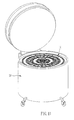
- a local enlarged view illustrating the second cover unit 504 according to the present embodiment As shown in FIG 12 , the outside of the second cover unit 504 is equipped with a plurality of fastening elements 513, which includes a shell body 551 and an embedded component 552 inserted into the shell body 551.
- the extent of one end of the embedded component 552 protruding outside the storage apparatus can be modified by adjusting the extent of the embedded component 552 being inserted into the shell body 551, such that one end of the embedded component 522 is able to connect with the inner wall of the storage tank so as to retain an interval between the storage apparatus and the storage tank.
- the embedded component 552 refers to a screw, and the embedded component 552 is inclinedly inserted into the shell body 551. Accordingly, the larger the extent of the embedded component 552 being inserted into the shell body 551 is, the larger the extent of one end of the embedded component 552 protruding outside the storage apparatus.
- the embedded component 552 can be adjusted to correspond to the larger interval, and thereby the storage apparatus can be stably located in the storage tank.
- the extent of the embedded component 552 being inserted into the shell body 551 can be adjusted to allow the extent of one end of the embedded component 552 protruding outside the storage apparatus to be smaller so as to correspond to the smaller interval.
- the storage apparatus according to the present invention merely includes the first circle and the second circle, the above-mentioned storage and retrieve action still can be performed.
- the storage apparatus of the present invention can be designed in a two-circle structure.
Abstract
Description
- T he present invention relates to a storage apparatus for storing products, and more particularly, to a storage apparatus in which independent storage-access operation, lowering cost and raising storage-access accuracy can be achieved.
- Currently, ultra-low temperature storage apparatuses are normally run under an ultra-low temperature environment (such as liquid nitrogen at -196°C), mostly for storing tissue, cellular products, or body fluids, such as cord blood, bone marrow, placenta, embryo, sperm, and ovum. However, since the use of specimens for cord blood, bone marrow, placenta, embryo, sperm, or ovum is not considerably immediate, an ultra-low temperature storage apparatus for storing the specimens over a long period of time becomes necessary. Biotechnology has been developed rapidly in recent decades. Cord blood in particular, containing abundant stem cells, has been widely adopted in medical therapy. The issue of cord blood storage has been of particular interest to those skilled in this art.
- Presently, there are several kinds of storage tanks for being used by cord blood banks, for example, 1) conventional liquid nitrogen storage tanks (MVE, Tayler-Wharton); and 2) automatic mechanical storage tanks (TG BioArchieve System).
- Conventional liquid nitrogen storage tank refers to an open-lid type. Each storage tank contains multiple storage racks, and each rack contains stacks of cartridges. Nevertheless, when an operator wishes to access one of the specimens, other specimens frozen in the same rack will be taken out together. The rapid change in temperature would possibly affect the viability of cells. Moreover, since the liquid nitrogen storage tanks are of open-lid type, upon proceeding with storage and access actions, such a design of open-lid type will make moisture appear above the surface of liquid nitrogen. As a result, the labeling of specimens is concealed by condensation above the surface of liquid nitrogen, and accuracy and speed of the storage and access are greatly affected.
- The mechanical storage tank relates to an automatic storage tank using hooks of robotic arms to hang the specimens on wall of the storage tank. Because the mechanical storage tank can perform the storage and access actions independently, the specimens at other storage positions are not affected. In view of the fact that the automatic mechanical storage tank employs the hooking measure to store the specimens, the specimens may fall to bottom of the storage tank when the storage tank rocks and the specimens accordingly swing loose. Based on this condition, when the specimens are stored with this measure, the storage tank, in principle, must not be moved or rocked in a great extent. Moreover, when the robotic arms are manipulated, moving upward or downward of the robotic arms will make moisture in the air permeate into joints of the robotic arms which are then frosted. The thus-impeded robotic arms, when manipulated, will produce relatively high frictional resistance, or even fail. Besides, the automatic mechanical storage tank relies on a computer for operation control, where electrical power is consumed, and after long-term use, precision electronic components may be damaged. In particular, the automatic mechanical storage tank is quite complex in design, and as such, high costs incurred in purchase and maintenance are the disadvantage.
- To solve the problems mentioned above, the present invention is to provide a storage apparatus for storing a plurality of products, including: a base, having a center region, a first circle region and a second circle region, the first circle region being between the center region and the second circle region; an axle unit, of which the bottom is supported on the center region of the base, the top thereof having a first guiding rail; a plurality of first storage units, of which the bottoms correspond to the first circle region of the base, the first storage units being arranged in a first circle and used for storing the products; a first storage-access unit, of which the bottom corresponds to the first circle region of the base, the first storage-access unit being arranged together with the first storage units to constitute the first circle and used for depositing and retrieving the products; a plurality of second storage units, of which the bottoms correspond to the second circle region of the base, the second storage units being arranged in a second circle and used for storing the products; a first rotating unit, connected with the tops of the first storage units; a first cover unit, connected with the tops of the second storage units and having a second guiding rail; and a plurality of first rolling units, connected with the first rotating unit and corresponding to the first guiding rail of the axle unit and the second guiding rail of the first cover unit for rolling, wherein the first storage-access unit, the first storage units and the second storage units individually have a plurality of compartments for receiving the products, and the first storage-access unit and the first storage units can rotate relative to the second storage units.
- According to the present invention, the storage apparatus is designed to have a circular arrangement structure so as to achieve the purpose of independent storage and access. In addition, the storage apparatus according to the present invention is not limited to have a two-circle structure. If necessary, the storage apparatus, based on the same principle of design, may have other multiple-circle structures, for instance, a four-circle structure. Thereby, the base may further have a third circle region and a fourth circle region, in which the third circle region is located between the second circle region and the fourth circle region, and the first cover unit may further have a third guiding rail, and accordingly, the storage apparatus may further include: a plurality of third storage units, of which the bottoms correspond to the third circle region of the base, the third storage units being arranged in a third circle and used for storing the products; a second storage-access unit, of which the bottom corresponds to the third circle region of the base, the second storage-access unit being arranged together with the third storage units to constitute the third circle and used for depositing and retrieving the products; a plurality of fourth storage units, of which the bottoms correspond to the fourth circle region of the base, the fourth storage units being arranged in a fourth circle and used for storing the products; a second rotating unit, connected with the tops of the third storage units; a second cover unit, connected with the tops of the fourth storage units and having a fourth guiding rail; and a plurality of second rolling units, connected with the second rotating unit and corresponding to the third guiding rail of the first cover unit and the fourth guiding rail of the second cover unit for rolling, wherein the second storage-access unit, the third storage units and the fourth storage units individually have a plurality of compartments for receiving the products, and the second storage-access unit and the third storage units can rotate relative to the fourth storage units.
- In the storage apparatus according to the present invention, the weight of the first rotating unit and the second rotating unit is mainly supported by the first guiding rail of the axle unit, the second and third guiding rails of the first cover unit, and the fourth guiding rail of the second cover unit.
- In the storage apparatus according to the present invention, the first storage-access unit and the second storage-access unit are movable and are provided for retrieving or depositing the products, whereas the first, second, third and fourth storage units are provided for storing the products.
- In detail, the storage apparatus according to the present invention may further include a transporting unit used for transporting the products. Accordingly, by the transporting unit, a product can be transported from the first storage-access unit to the second storage unit so as to complete a storage action. On the contrary, a retrieve action can be performed by transporting a product from the second storage unit to the first storage-access unit. The compartments 23 in the first storage-access device 13 and the first storage device 14 correspond to the compartments 23 in the second storage-access device 17 and the second storage device 18, so that the products in the first storage-access device 13, the first storage device 14, the second storage-access device 17, and the second storage device 18 can be transferred to one another. Also, for the fourth storage units, the storage and retrieve action can be performed by the second storage-access unit. In addition, when using the storage apparatus according to the present invention, it should be noted that at least one second storage unit and at least one fourth storage unit have to be reserved in such way that no product is stored therein so as to be used as temporary storage regions for the storage and retrieve action on the first and third storage units. In detail, in the case of storing a product into the compartment of the first storage unit, first, through the above-mentioned storage action, the product is transported into the second storage unit as the temporary storage region; subsequently, the first rotating unit is rotated to allow the first storage unit where the product is tending to be stored to correspond to the second storage unit as temporary storage region; and finally, the product temporarily stored in the second storage unit is transported to the first storage unit so as to complete the storage action on the first storage unit. On the contrary, in the case of retrieving a product from the compartment of the first storage unit, first, the product is transported from the first storage unit into the second storage unit as the temporary storage region; subsequently, the first rotating unit is rotated to allow the first storage-access unit to correspond to the second storage unit as temporary storage region; and finally, the product temporarily stored in the second storage unit is transported to the first storage-access unit so as to retrieve the product stored in the first storage unit and thereby complete the retrieve action. Also, through the above-mentioned operation, the storage and retrieve action can be performed for the third storage units.
- In the storage apparatus according to the present invention, the transporting unit can be designed as a mechanism able to transfer the products in the compartments. Preferably, the transporting unit includes a telescopic element and a control element connected with the telescopic element, in which, the telescopic element can be extended toward the compartment by operating the control element so as to transport a product. Herein, the control element may include a rod, a handle fitted on the rod, and a binding rod located inside of the rod, in which the telescopic element is connected with one end of the binding rod and the handle can be moved along the rod to allow the telescopic element to correspond to compartments at various depths.
- The storage apparatus according to the present invention may further include a first rotating ring and a second rotating ring, which are connected with the bottoms of the first storage units and correspond to an inside track and an outside track of the first circle region, respectively. Also, the storage apparatus according to the present invention may include a third rotating ring and a fourth rotating ring, which are connected with the bottoms of the third storage units and correspond to an inside track and an outside track of the third circle region, respectively. Herein, the first, second, third and fourth rotating rings are not connected with the base. Accordingly, when the first and third storage units rotate, the first, second, third and fourth rotating rings will rotate, respectively corresponding to the first circle region and the third circle region of the base. In addition, the first, second, third and fourth rotating rings can ensure the first and third storage units being correctly aligned, and prevent the first and third storage units from misalignment.
- In the storage apparatus according to the present invention, the first and second rotating rings may have a plurality of first positioning portions, corresponding to locations of the first storage units, and the second circle region of the base may have a plurality of second positioning portions, corresponding to locations of the second storage units, for anchoring the bottoms of the first storage units and the second storage units. Also, the third and fourth rotating rings may have a plurality of third positioning portions, corresponding to locations of the third storage units, and the fourth circle region of the base may have a plurality of fourth positioning portions, corresponding to locations of the fourth storage units, for anchoring the bottoms of the third storage units and the fourth storage units. Herein, the first, second and third positioning portions may be designed as any structure having effectiveness of positioning, such as slots, holes, and so forth. Preferably, the first, second and third positioning portions have a hole-like structure so as to lower manufacturing cost and to reduce manufacturing processing.
- In the storage apparatus according to the present invention, the first rotating unit may have a first guiding element, corresponding to the location of the first storage-access unit, so that the first storage-access unit, upon insertion thereinto, can be guided to an accurate position. Also, the second rotating unit may have a second guiding element, corresponding to the location of the second storage-access unit, so that the second storage-access unit, upon insertion thereinto, can be guided to an accurate position. In addition, the bottoms of the first guiding element and the first storage-access unit may be provided with alignment holes corresponding to each other, so that the first storage-access unit, upon insertion into the first guiding element, can be guided to an accurate position through alignment between the alignment hole of the first storage-access unit and the alignment hole of the first guiding element. Also, the bottoms of the second guiding element and the second storage-access unit may be provided with alignment holes corresponding to each other, so that the second storage-access unit, upon insertion into the second guiding element, can be guided to an accurate position through alignment between the alignment hole of the second storage-access unit and the alignment of the second guiding element. Herein, the shape of the alignment holes is not particularly limited, and may be, for example, rectangular. Furthermore, the first storage-access unit may be equipped with at least one positioning element (such as ball plungers), and the first guiding element may be provided with at least one positioning hole corresponding to the positioning element. Accordingly, in the case of the first storage-access unit being inserted into the first guiding element, the combination of the positioning elements and the positioning holes can achieve the purpose for positioning. Also, the second storage-access unit may be equipped with at least one positioning element (such as ball plungers), and the second guiding element may be provided with at least one positioning hole corresponding to the positioning element.
- The storage apparatus according to the present invention may further include a plurality of first supporting rods located between the first cover unit and the base to connect the first cover unit with the base so as to reinforce the connecting relationship therebetween. Also, the storage apparatus according to the present invention may further include a plurality of second supporting rods located between the second cover unit and the base to connect the second cover unit with the base.
- The storage apparatus according to the present invention may further include a plurality of first positioning units connected with the first rotating unit and corresponding to the first cover to achieve positioning action, so that the first rotating unit can reach to a target position when the first rotating unit stops rotating. In detail, the first cover unit may be provided with a plurality of positioning holes corresponding to the first positioning units. As such, a combination of the first positioning units and the positioning holes can provide resistance, so that the first rotating unit may not rotate too fast, and that when it stops rotating, the first storage-access unit and the first storage unit can accurately align with the second storage unit. Also, the storage apparatus according to the present invention may further include a plurality of second positioning units connected with the second rotating unit and corresponding to the second cover to achieve positioning action, so that the second rotating unit can reach to a target position when it stops rotating.
- In the storage apparatus according to the present invention, each of the compartments may be equipped with a blocking element to prevent the products stored in the compartments from falling out. Herein, the blocking element is not limited to any specific configuration so long as the purpose of preventing the products from falling out of the compartments, due to rocking of the storage apparatus, can be achieved. Preferably, the blocking element is an elastic steel slice.
- In the storage apparatus according to the present invention, the first storage-access unit, the first storage units, the second storage units, the second storage-access unit, the third storage units, and the fourth storage units may be each provided with an open side and, oppositely, a closed side. When assembled, the open sides of the first storage-access unit and the first storage units face toward the open sides of the second storage units, and the open sides of the second storage-access unit and the third storage units face toward the open sides of the fourth storage units, such that the products can be transferred in the storage apparatus. The closed sides can prevent the products from falling out. Preferably, the first storage-access unit, the first storage units, the second storage units, the second storage-access unit, the third storage units, and the fourth storage units are each provided, at its closed side, with a through guiding portion, such that the transporting unit can be put into the through guiding portion for performing the storage and retrieve action.
- The storage apparatus according to the present invention may further include a plurality of cartridges for containing the products, such as specimens, where the cartridges are arranged in the compartments. The cartridges can store products of any package type (such as tube-typed package), and that the shapes of the cartridges are not to be limited so long as the cartridges can be moved among the compartments conveniently.
- The storage apparatus according to the present invention may further include a cover plate which covers the top of the storage apparatus so as to prevent temperature loss or invasion of foreign matter, and in particular can prevent the storage apparatus from being effected by surface moisture, so that operators can carry out the access-storage job accurately. Herein, the cover plate can be of any materials having an anti-fogging feature. Preferably, the cover plate refers to an acrylic plate or high-strength glass.
- According to the present invention, a storage system is further provided for storing a plurality of products, which includes: a storage tank; a liquid in the storage tank; and the above-mentioned storage apparatus, disposed in the storage tank. According to the present invention, the storage tank can keep the liquid under a certain temperature suitable for storing the products. In the present invention, the liquid may be liquid nitrogen. As such, the storage system, according to the present invention, can be used for storing specimens, such as stem cells. Additionally, the storage apparatus according to the present invention may further include a fastening element, equipped on the outside of the second cover unit to retain an interval between the storage apparatus and the storage tank. Preferably, the fastening element includes a shell body and an embedded component. Herein, the embedded component is inserted into the shell body and one end of the embedded component is able to protrude outside the storage apparatus to connect with the inner wall of the storage tank. More preferably, the embedded component is inclinedly inserted into the shell body. Herein, the embedded component is not particularly limited, and may be, for example, a screw.
- According to the present invention, since the storage apparatus and the storage system using the same relate to manual manipulation mechanism, system shutdown due to electric power failure or robotic fault can be avoided. In addition, since the mechanism is relatively simple, manufacturing cost and maintenance difficulty can be lowered. Further, the transmission principle applied in the present invention can perform the storage and access actions independently, so that the specimens not to be accessed remain at the original position, and that otherwise loss of the viability of cell on the specimens due to abrupt temperature change can be avoided. Besides, in the present invention, the cover plate can perform an anti-fog effect so as to avoid the problem of visual blur due to condensation of moisture above the liquid nitrogen, and that accuracy and speed of access and storage can be enhanced.
- Other objects, advantages, and novel features of the present invention will become more apparent from the following detailed description when taken in conjunction with the accompanying drawings.
-
-
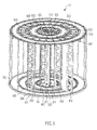
FIG. 1 is a perspective view illustrating a storage apparatus according to one preferred embodiment of the present invention; -
FIG. 2 is an exploded view illustrating a storage apparatus according to one preferred embodiment of the present invention; -
FIG. 3 is a perspective view illustrating a first storage-access unit and a first guiding element in a storage apparatus according to one preferred embodiment of the present invention; -
FIG. 4 is an exploded view illustrating an axle unit and a first rotating unit in a storage apparatus according to one preferred embodiment of the present invention; -
FIG. 5 is a local enlarged view illustrating the top of a storage apparatus according to one preferred embodiment of the present invention; -
FIG 6 is a cross-sectional view along the section line inFIG 5 ; -
FIG 7 is a perspective view illustrating a first storage-access unit and a first storage unit according to one preferred embodiment of the present invention; -
FIG. 8A is a perspective view illustrating a transporting unit according to one preferred embodiment of the present invention; -
FIG. 8A is a perspective view illustrating a transporting unit according to one preferred embodiment of the present invention; -
FIG. 8C is a cross-sectional view illustrating a transporting unit according to one preferred embodiment of the present invention; -
FIGs. 9A to 9B are perspective views illustrating actions of access and storage of a storage apparatus according to one preferred embodiment of the present invention; -
FIG 10 is a perspective view, in outer appearance, illustrating a storage apparatus according to one preferred embodiment of the present invention; -
FIG. 11 is a perspective view illustrating a storage system according to one preferred embodiment of the present invention; and -
FIG 12 is a local enlarged view illustrating the top of a second cover unit in a storage apparatus according to one preferred embodiment of the present invention. - Referring to
FIG 1 , a perspective view illustrating a storage apparatus according to the present embodiment, the storage apparatus 10 mainly includes: a base 101; an axle unit 301, of which the bottom is supported on the base 101; a first storage-access unit 401 and a plurality of first storage units 402 (only one is shown in the figure), of which the bottoms correspond to the base 101, the first storage units 402 together with the first storage-access unit 401 being arranged in a first circle and connected with a first rotating ring 201 and a second rotating ring 202 at their bottoms; a plurality of second storage units 403 (only one is shown in the figure), of which the bottoms correspond to the base 101, the second storage units 403 being arranged in a second circle; a second storage-access unit 404 and a plurality of third storage units 405 (only one is shown in the figure), of which the bottoms correspond to the base 101, the third storage units 405 together with the second storage-access unit 404 being arranged in a third circle and connected with a third rotating ring 203 and a fourth rotating ring 204 at their bottoms; a plurality of fourth storage units 406 (only one is shown in the figure), of which the bottoms correspond to the base 101, the fourth storage units 406 being arranged in a fourth circle; a first rotating unit 501, connected with the tops of the first storage units 402; a first cover unit 502, connected with the tops of the second storage units 403; a second rotating unit 503, connected with the tops of the third storage units 405; a second cover unit 504, connected with the tops of the fourth storage units 406; a plurality of first rolling units 601 and a plurality of first positioning units 602, connected with the first rotating unit 501; and a plurality of second rolling units 603 and a plurality of second positioning units 604, connected with the second rotating unit 503. Herein, the first storage-access unit 401 and thefirst storage units 402 can rotate relative to thesecond storage units 403, and the second storage-access unit 404 and thethird storage units 405 can rotate relative to thefourth storage units 406. - According to the present embodiment, the
storage apparatus 10 further includes a plurality of first supportingrods 701 and a plurality of second supportingrods 702. Herein the first supportingrods 701 are disposed between thefirst cover unit 502 and the base 101 to connect thefirst cover unit 502 and thebase 101, and the second supportingrods 702 are disposed between thesecond cover unit 504 and the base 101 to connect thesecond cover unit 504 and thebase 101. Accordingly, the first storage-access unit 401 and thefirst storage units 402 can rotate relative to thesecond storage units 403 through the firstrotating unit 501, and the second storage-access unit 404 and thethird storage units 405 can rotate relative to thefourth storage units 406 through the secondrotating unit 503. In addition, with the help of the movable first storage-access unit 401 and the movable second storage-access unit 404, actions of storage and access for thestorage apparatus 10, according to the present embodiment, can be performed without effecting unused products deposited in thefirst storage units 402, thesecond storage units 403, thethird storage units 405 and thefourth storage units 406, so as to avoid damage to activity of products due to inappropriate temperature increase. - As shown in
FIG. 1 , in thestorage apparatus 10 according to the present embodiment, since the complex rotating mechanism is designed at the top of thestorage apparatus 10, maintenance and assembly for the apparatus can be undertaken easily. - Referring to
FIGs. 2 to 7 , the structure and combination of elements of thestorage apparatus 10 are detailed as follows: - (1) As shown in
FIG 2 , thebase 101 has acenter region 111, afirst circle region 112, asecond circle region 113, athird circle region 114 and a fourth circle region 115, in which thefirst circle region 112 is located between thecenter region 111 and thesecond circle region 113, and thethird circle region 114 is located between thesecond circle region 113 and the fourth circle region 115. In addition, the firstrotating ring 201 and the secondrotating ring 202 are connected with the bottoms of thefirst storage units 402 and correspond to an inside track and an outside track of thefirst circle region 112 of thebase 101, respectively. Also, the thirdrotating ring 203 and the fourthrotating ring 204 are connected with the bottoms of thethird storage units 405 and correspond to an inside track and an outside track of thethird circle region 114 of thebase 101, respectively. Herein, the firstrotating ring 201, the secondrotating ring 202, the thirdrotating ring 203 and the fourthrotating ring 204 are not connected with the base. Accordingly, when thefirst storage units 402 andthird storage units 405 rotate, the firstrotating ring 201, the secondrotating ring 202, the thirdrotating ring 203 and the fourthrotating ring 204 will rotate, respectively corresponding to thefirst circle region 112 and thethird circle region 114 of thebase 101.
Moreover, for anchoring the bottoms of thefirst storage units 402, thesecond storage units 403, thethird storage units 404 and thefourth storage units 406, the firstrotating ring 201 and the secondrotating ring 202 have a plurality offirst positioning portions 211, corresponding to locations of thefirst storage units 402; thesecond circle region 113 of thebase 101 has a plurality ofsecond positioning portions 121, corresponding to locations of thesecond storage units 403; the thirdrotating ring 203 and the fourthrotating ring 204 have a plurality ofthird positioning portions 212, corresponding to locations of thethird storage units 405; and the fourth circle region 115 of thebase 101 has a plurality offourth positioning portions 122, corresponding to locations of thefourth storage units 406. Accordingly, the bottoms of the plural first storage units 402 (only one is shown in the figure) correspond to thefirst circle region 112 of the base 101 to be arranged in a first circle; the bottoms of the plural second storage units 403 (only one is shown in the figure) correspond to thesecond circle region 113 of the base 101 to be arranged in a second circle; the bottoms of the plural third storage units 405 (only one is shown in the figure) correspond to thethird circle region 114 of the base 101 to be arranged in a third circle; and the bottoms of the plural fourth storage units 406 (only one is shown in the figure) correspond to the fourth circle region 115 of the base 101 to be arranged in a fourth circle.
In the present embodiment, thefirst positioning portions 211, thesecond positioning portions 121, thethird positioning portions 212 and thefourth positioning portions 122 refer to holes, such that theprotrusions 411 at the bottoms of thefirst storage units 402, thesecond storage units 403, thethird storage units 405 and thefourth storage units 406 can be inserted into thefirst positioning portions 211, thesecond positioning portions 121, thethird positioning portions 212 and thefourth positioning portions 122, respectively. - (2) Referring to
FIG. 2 , theaxle unit 301 is supported on thecenter region 111 of thebase 101, and the firstrotating unit 501, thefirst cover unit 502, the secondrotating unit 503 and thesecond cover unit 504 are connected with the tops of thefirst storage units 402, thesecond storage units 403, thethird storage units 405 and thefourth storage units 406, respectively. In addition, the firstrotating unit 501 and the secondrotating unit 503 have afirst guiding element 511 and asecond guiding element 512, respectively. Herein, theprotrusions 521 at the bottoms of thefirst guiding element 511 and thesecond guiding element 512 are respectively inserted into thefirst positioning portions 211 and thethird positioning portions 212, and respectively correspond to locations of the first storage-access unit 401 and the second storage-access unit 404, so that the first storage-access unit 401 and the second storage-access unit 404, upon insertion thereinto, can be guided to an accurate position. Accordingly, the first storage-access unit 401 together with thefirst storage units 402 is arranged in a first circle, whereas the second storage-access 404 together with thethird storage units 405 is arranged in a third circle.
Further referring toFIG 3 , the bottoms of thefirst guiding element 511 and the first storage-access unit 401 are provided withalignment holes access unit 401, upon insertion into thefirst guiding element 511, can be guided to an accurate position through alignment between thealignment hole 422 of the first storage-access unit 401 and thealignment hole 522 of thefirst guiding element 511. Additionally, as shown inFIG. 3 , the first storage-access unit 401 is equipped with at least one positioning element 441 (in the present embodiment, ball plungers are used as the positioning elements 441), whereas thefirst guiding element 511 is provided with at least onepositioning hole 523 corresponding to thepositioning element 441. Accordingly, in the case of the first storage-access unit 401 being inserted into thefirst guiding element 511, the combination of thepositioning elements 441 and the positioning holes 523 can achieve the purpose of positioning. Also, the second storage-access unit 404 and thesecond guiding element 512 shown inFIG 2 are designed in a structure as illustrated in the first storage-access unit 401 and thefirst guiding element 511, and thereby the description about the structures of the second storage-access unit 404 and thesecond guiding element 512 will not be repeated.
Besides, a plurality of first supporting rods 701 (only one is shown in the figure) is further located between thefirst cover unit 502 and the base 101 to reinforce the connecting relationship between thefirst cover unit 502 and thebase 101. Also, a plurality of second supportingrods 702 is further located between thesecond cover unit 504 and the base 101 to reinforce the connecting relationship between thesecond cover unit 504 and thebase 101. - (3) Referring to
FIG 2 , a plurality of first rollingunits 601 and a plurality offirst positioning units 602 are connected with the firstrotating unit 501, whereas a plurality of second rollingunits 603 and a plurality ofsecond positioning units 604 are connected with the secondrotating unit 503.
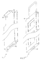
In more detail, referring toFIG. 4 together withFIG 5 ,FIG 4 is an exploded view illustrating theaxle unit 301 and the firstrotating unit 501, andFIG 5 is a local enlarged view illustrating the top of the storage apparatus. As shown inFIGs. 4 and5 , the top of theaxle unit 301 is provided with afirst guiding rail 311, and as shown inFIG. 5 , thefirst cover unit 502 is provided with asecond guiding rail 541 and athird guiding rail 542, whereas thesecond cover unit 504 is provided with afourth guiding rail 543. Accordingly, through the rolling of the first rollingunits 601 in the first guidingrail 311 and thesecond guiding rail 541, the firstrotating unit 501 can rotate. Also, through the rolling of the second rollingunits 603 in thethird guiding rail 542 and the fourth guidingrail 543, the secondrotating unit 503 can rotate.
Moreover, as shown inFIG 5 , in the present embodiment, the secondrotating unit 503 is provided with thesecond positioning units 604. Referring toFIG. 6 , there is shown a cross-sectional view along the section line inFIG. 5 . Thesecond positioning units 604 can achieve positioning action throughball plungers 611, whereas thesecond cover unit 504 has a plurality ofpositioning holes 531, corresponding to the ball plungers 611. Accordingly, the combination of thesecond positioning units 604 and the positioning holes 531 can provide resistance, so that the secondrotating unit 503 can reach to a target position when it stops rotating. Also, as shown inFIG. 5 , a plurality of first positioning units 602 (in the present embodiment, ball plungers are applied in thefirst positioning units 602 for positioning action is retained on the firstrotating unit 501, whereas thefirst cover unit 502 has a plurality of positioning holes (referring to the positioning holes 531 shown inFIG. 6 ), corresponding to thefirst positioning units 602, and accordingly, the resistance can be provided while the firstrotating unit 501 rotates so as to achieve the purpose for positioning. - (4) As shown in
FIG. 2 , each of the first storage-access unit 401, thefirst storage units 402, thesecond storage units 403, the second storage-access unit 404, thethird storage units 405 and thefourth storage units 406 has a plurality ofcompartments 412. Herein, thecompartments 412 in the first storage-access unit 401 and thefirst storage units 402 correspond to thecompartments 412 in thesecond storage units 403, whereas thecompartments 412 in the second storage-access unit 404 and thethird storage units 405 correspond those in thefourth storage units 405, so that the products can be transferred from one compartment to another one.
In more detail, referring toFIG. 7 , each of the first storage-access unit 401 and thefirst storage units 402 is provided with anopen side 413 and, oppositely, a closed side 141. Herein, each of the first storage-access unit 401 and thefirst storage units 402 has a through guidingportion 421 at itsclosed side 414, such that a transportingunit 801 shown inFIG. 8A can be inserted thereinto to transport the products stored in thecompartment 412 and to thereby complete the access action. In addition, as shown inFIG. 7 , each of thecompartments 412 in the first storage-access unit 401 and thefirst storage units 402 is equipped with a blockingelement 431 to prevent the products stored in thecompartments 412 from falling out. In the present embodiment, an elastic steel slice is used as the blockingelement 431.
As shown inFIG 2 , the structure of the second storage-access unit 404 is the same as that of the first storage-access unit 401, whereas the structures of thesecond storage units 403, thethird storage units 405 and thefourth storage units 406 are the same as that of thefirst storage units 402, and thereby the description about the structures of the second storage-access unit 404, thesecond storage units 403, thethird storage units 405 and thefourth storage units 406 will not be repeated.
Referring toFIG 2 , when assembled, the open sides of the first storage-access unit 401 and thefirst storage units 402 face toward the open sides of thesecond storage units 403, such that the access action can be performed and the closed sides can prevent the products from falling. Also, the open sides of the second storage-access unit 404 and thethird storage units 405 face toward the open sides of thefourth storage units 406. - (5) Referring to
FIG. 8A , there is shown a perspective view illustrating a transportingunit 801 used in the present embodiment. As shown inFIG 8A , the transportingunit 801 according to the present embodiment includes atelescopic element 811 and acontrol element 812 connected with thetelescopic element 811. Herein, operating thecontrol element 812 will cause the deformation of thetelescopic element 811, such that thetelescopic element 811 will present its extended and retracted forms. Accordingly, thetelescopic element 811 can be extended toward and thereby transport the products stored in the compartments to perform the access action. In detail, as shown inFIG. 8A , thecontrol element 812 of the transportingunit 801 includes arod 821, ahandle 822 fitted on therod 821, and abinding rod 823 located inside of therod 821, in which thetelescopic element 811 is connected with one end of thebinding rod 823. - In addition, referring to
FIG. 8B , there is shown an exploded view illustrating the transportingunit 801. As shown inFIG 8B , thetelescopic element 811 consists of afirst linkage 851 and asecond linkage 852 connected with each other. Herein, one end of thefirst linkage 851 is fixed at therod 821, and the other end thereof is equipped with awheel 853 to reduce friction. Meanwhile, one end of thesecond linkage 852 is connected with one end of thebinding rod 823. Accordingly, an applied force can be transmitted from thebinding rod 823 to thesecond linkage 852, such that the portion connecting thesecond linkage 852 with thebinding rod 823 will move along thegrooved rail 854 of therod 821, resulting in the deformation of thetelescopic element 811. In addition, as shown inFIG 8B , the bindingrod 823 is provided with a plurality ofblockers 831, and therod 821 is provided with a plurality of positioning holes 832. Herein, theblockers 831 and the positioning holes 832 correspond to compartments at various depths. - Subsequently, referring to
FIGs. 8B and8C, FIG. 8C shows a cross-sectional view of the transporting unit. As shown inFIGs. 8B and8C , thehandle 822 has apositioning component 833 and atriggered component 834. Herein, thepositioning end 841 of theposition component 833 can be extended and retracted by operating thefirst knob 843. Also, the forcingend 842 of thetriggered component 834 can be extended and retracted by operating thesecond knob 844. In detail, as shown inFIG 8C , when thepositioning end 841 of theposition component 833 is stretched out by controlling thefirst knob 843, thepositioning end 841 of theposition component 833 will be combined with thepositioning hole 832 of therod 821 so as to achieve the purpose for positioning. Accordingly, thehandle 822 can be disposed at various locations on therod 821 by the combining thepositioning component 833 withvarious positioning holes 832, such that thetelescopic element 811 can be controlled to correspond to the compartments at various depths. Meanwhile, referring toFIG. 8C , after thehandle 822 has been positioned, the forcingend 842 of thetriggered component 834 is extended by controlling thesecond knob 844, and then blocked at the lower edge of theblocker 831. Accordingly, when force is applied on thetriggered component 834, the forcingend 842 of thetriggered component 834 will press theblocker 831 upward, resulting in thebinding rod 823 moving upward and thereby thetelescopic element 811 deforming and being extended outward. On the contrary, in the case of adjusting the location of thehandle 822 on therod 821, as shown inFIG. 8C , thepositioning end 841 of thepositioning component 833 is retracted by controlling thefirst knob 843 and thereby separated from thepositioning hole 832 of therod 821 and, meanwhile, the forcingend 842 of thetriggered component 834 is also retracted and thereby separated from theblocker 832. Accordingly, thehandle 822 can be moved along therod 821 to adjust the location of thehandle 822 on therod 821. In addition, as shown inFIGs. 8B and8C , anelastic element 861 is disposed between one end of the binding rod 823 (i.e. the end connected with the second linkage 852) and one end of therod 821 for providing elastic recovery force, that will cause thetelescopic element 811 to become retracted from its extended form. - Based on the above-mentioned mechanism, referring to
FIGs. 8A to 8C , thetelescopic element 811 is retracted when no force is applied on thetriggered component 834 of thehandle 822, whereas thetelescopic element 811 is extended outward while force is applied on thetriggered component 834 and thereby the forcingend 842 of thetriggered component 834 presses theblocker 831 upward. Accordingly, in the case of force being applied on thetriggered component 834, the bindingrod 823, disposed inside therod 821, is moved upward, and thereby thetelescopic element 811 deforms and is extended outward, such that the storage and retrieve action can be performed. After that, when force is removed, the elastic recovery force provided by theelastic element 861 will cause thetelescopic element 811 to become retracted from its extended form. - Accordingly, referring to
FIGs. 9A to 9B , the first storage-access unit 401 and thesecond storage unit 403 are shown for illustrating the storage and retrieve action, in which the product is received in acartridge 901 and then stored in thecompartment 412.FIGs. 9A to 9B show the action of storing a product into thecompartment 412 of thesecond storage unit 403. As shown inFIG. 9A , the location of thehandle 822 of the transportingunit 801 on therod 821 is first adjusted to allow thetelescopic element 811 of the transportingunit 801 to correspond to the location of the compartment into which the product is intended to be stored. Subsequently, as shown inFIG. 9A , the transportingunit 801 is inserted into the through guiding portion of the first storage-access unit 401, in which thetelescopic element 811 of the transportingunit 801 is retracted due to no force being applied. Next, as shown inFIG 9B , force is applied on thetriggered component 834 of thehandle 822, and thereby thebinding rod 823 is moved upward, resulting in thetelescopic element 811 of the transportingunit 801 being extended toward thecompartment 412 where thecartridge 901 is disposed, such that thecartridge 901 can be transported into thecompartment 412 in thesecond storage unit 403. Accordingly, the action of storing the product into thesecond storage unit 403 is accomplished through the first storage-access unit 401. On the contrary, the retrieve action can be performed by transporting thecartridge 901 from thesecond storage unit 403 into the first storage-access unit 401. Also, the product can be stored into or picked from the fourth storage unit by the second storage-access unit, according to the storage and retrieve action illustrated byFIGs. 9A and9B . - In addition, when using the storage apparatus according to the present invention, it should be noted that at least one second storage unit and at least one fourth storage unit have to be reserved in such way that no product is stored therein so as to be used as temporary storage regions for the storage and retrieve action on the first and third storage units. In detail, in the case of storing a product into the compartment of the first storage unit, first, through the storage action shown in
FIGs. 9A to 9B , the product is transported into the second storage unit as the temporary storage region; subsequently, the first rotating unit is rotated to allow the first storage unit where the product is tending to be stored to correspond to the second storage unit as temporary storage region; and finally, the product temporarily stored in the second storage unit is transported to the first storage unit so as to complete the storage action on the first storage unit. On the contrary, in the case of retrieving a product from the compartment of the first storage unit, first, the product is transported from the first storage unit into the second storage unit as the temporary storage region; subsequently, the first rotating unit is rotated to allow the first storage-access unit to correspond to the second storage unit as temporary storage region; and finally, the product temporarily stored in the second storage unit is transported to the first storage-access unit so as to pick up the product stored in the first storage unit and thereby complete the retrieve action. Also, through the above-mentioned operation, the storage and retrieve action can be performed for the third storage units. - With reference to
FIG 10 , there is shown a perspective view, in outer appearance, illustrating thestorage apparatus 10 according to the present embodiment. - Finally, as shown in
FIG 11 , thestorage apparatus 10 is disposed in astorage tank 20 filled with a liquid suitable for storing specimens (in the present embodiment, the liquid refers to liquid nitrogen), so that a storage system for storing specimens can be provided. In addition, referring toFIG. 12 , there is shown a local enlarged view illustrating thesecond cover unit 504 according to the present embodiment. As shown inFIG 12 , the outside of thesecond cover unit 504 is equipped with a plurality offastening elements 513, which includes ashell body 551 and an embeddedcomponent 552 inserted into theshell body 551. Herein, the extent of one end of the embeddedcomponent 552 protruding outside the storage apparatus can be modified by adjusting the extent of the embeddedcomponent 552 being inserted into theshell body 551, such that one end of the embeddedcomponent 522 is able to connect with the inner wall of the storage tank so as to retain an interval between the storage apparatus and the storage tank. In detail, in the present embodiment, the embeddedcomponent 552 refers to a screw, and the embeddedcomponent 552 is inclinedly inserted into theshell body 551. Accordingly, the larger the extent of the embeddedcomponent 552 being inserted into theshell body 551 is, the larger the extent of one end of the embeddedcomponent 552 protruding outside the storage apparatus. In the case of the interval between the storage apparatus and the storage tank being larger, the embeddedcomponent 552 can be adjusted to correspond to the larger interval, and thereby the storage apparatus can be stably located in the storage tank. On the contrary, in the case of the interval between the storage apparatus and the storage tank being smaller, the extent of the embeddedcomponent 552 being inserted into theshell body 551 can be adjusted to allow the extent of one end of the embeddedcomponent 552 protruding outside the storage apparatus to be smaller so as to correspond to the smaller interval. - Additionally, when the storage apparatus according to the present invention merely includes the first circle and the second circle, the above-mentioned storage and retrieve action still can be performed. Thereby, according to the requirement, the storage apparatus of the present invention can be designed in a two-circle structure.
- Although the present invention has been explained in relation to its preferred embodiments, it is to be understood that many other possible modifications and variations can be made without departing from the scope of the invention as hereinafter claimed.
Claims (25)
- A storage apparatus for storing a plurality of products, comprising:a base, having a center region, a first circle region and a second circle region, the first circle region being between the center region and the second circle region;an axle unit, of which the bottom is supported on the center region of the base, the top thereof having a first guiding rail;a plurality of first storage units, of which the bottoms correspond to the first circle region of the base, the first storage units being arranged in a first circle and used for storing the products;a first storage-access unit, of which the bottom corresponds to the first circle region of the base, the first storage-access unit being arranged together with the first storage units to constitute the first circle and used for depositing and retrieving the products;a plurality of second storage units, of which the bottoms correspond to the second circle region of the base, the second storage units being arranged in a second circle and used for storing the products;a first rotating unit, connected with the tops of the first storage units;a first cover unit, connected with the tops of the second storage units and having a second guiding rail; anda plurality of first rolling units, connected with the first rotating unit and correspond to the first guiding rail of the axle unit and the second guiding rail of the first cover unit for rolling,wherein the first storage-access unit, the first storage units and the second storage units individually have a plurality of compartments for receiving the products, and the first storage-access unit and the first storage units can rotate relative to the second storage units
- The storage apparatus as claimed in claim 1, further comprising a first rotating ring and a second rotating ring, connected with the bottoms of the first storage units and corresponding to an inside track and an outside track of the first circle region, respectively.
- The storage apparatus as claimed in claim 2, wherein the first rotating ring and the second rotating ring have a plurality of first positioning portions, corresponding to locations of the first storage units, and the second circle region of the base has a plurality of second positioning portions, corresponding to locations of the second storage units, for anchoring the bottoms of the first storage units and the second storage units.
- The storage apparatus as claimed in claim 1, wherein the first rotating unit has a first guiding element, corresponding to the location of the first storage-access unit to allow the first storage-access unit to be inserted thereinto.
- The storage apparatus as claimed in claim 1, further comprising a plurality of first supporting rods located between the first cover unit and the base to connect the first cover unit with the base.
- The storage apparatus as claimed in claim 1, further comprising a plurality of first positioning units connected with the first rotating unit and corresponding to the first cover to achieve positioning action so as to allow the first rotating unit to reach to a target position when the first rotating unit stops rotating.
- The storage apparatus as claimed in claim 1, wherein each of the compartments is equipped with a blocking element to prevent the products stored in the compartments from falling out.
- The storage apparatus as claimed in claim 7, wherein the blocking element is an elastic steel slice.
- The storage apparatus as claimed in claim 1, further comprising a transporting unit for transporting the products.
- The storage apparatus as claimed in claim 9, wherein the transporting unit comprises a telescopic element and a control element connected with the telescopic element, wherein the telescopic element can be extended toward the compartments for transporting the products by operating the control element.
- The storage apparatus as claimed in claim 10, wherein the control element includes a rod, a handle fitted on the rod, and a binding rod located inside of the rod, wherein the telescopic element is connected with one end of the binding rod and the handle is able to be moved along the rod.
- The storage apparatus as claimed in claim 10, wherein the first storage-access unit, the first storage units and the second storage units are each provided with an open side and, oppositely, a closed side, and each provided with a through guiding portion at its closed side to allow the transporting unit to be put into the through guiding portion.
- The storage apparatus as claimed in claim 1, further comprising a plurality of cartridges used for receiving the products and disposed in the compartments.
- The storage apparatus as claimed in claim 1, wherein the base further has a third circle region and a fourth circle region, the third circle region being located between the second circle region and the fourth circle region, the first cover unit further has a third guiding rail, and the storage apparatus further comprises:a plurality of third storage units, of which the bottoms correspond to the third circle region of the base, the third storage units being arranged in a third circle and used for storing the products;a second storage-access unit, of which the bottom corresponds to the third circle region of the base, the second storage-access unit being arranged together with the third storage units to constitute the third circle and used for depositing and retrieving the products;a plurality of fourth storage units, of which the bottoms correspond to the fourth circle region of the base, the fourth storage units being arranged in a fourth circle and used for storing the products;a second rotating unit, connected with the tops of the third storage units;a second cover unit, connected with the tops of the fourth storage units and having a fourth guiding rail; anda plurality of second rolling units, connected with the second rotating unit and correspond to the third guiding rail of the first cover unit and the fourth guiding rail of the second cover unit for rolling,wherein the second storage-access unit, the third storage units and the fourth storage units individually have a plurality of compartments for receiving the products, and the second storage-access unit and the third storage units can rotate relative to the fourth storage units
- The storage apparatus as claimed in claim 14, further comprising a first rotating ring, a second rotating ring, a third rotating ring and a fourth rotating ring, wherein the first rotating ring and the second rotating ring are connected with the bottoms of the first storage units and correspond to an inside track and an outside track of the first circle region, respectively, and the third rotating ring and the fourth rotating ring are connected with the bottoms of the third storage units and correspond to an inside track and an outside track of the third circle region, respectively.
- The storage apparatus as claimed in claim 15, wherein the first rotating ring and the second rotating ring have a plurality of first positioning portions, corresponding to locations of the first storage units, the second circle region of the base has a plurality of second positioning portions, corresponding to locations of the second storage units, the third rotating ring and the fourth rotating ring have a plurality of third positioning portions, corresponding to locations of the third storage units, and the fourth circle region of the base has a plurality of fourth positioning portions, corresponding to locations of the fourth storage units, for anchoring the bottoms of the first storage units, the second storage units, the third storage units and the fourth storage units.
- The storage apparatus as claimed in claim 14, wherein the first rotating unit has a first guiding element, corresponding to the location of the first storage-access unit, and the second rotating unit has a second guiding element, corresponding to the location of the second storage-access unit to allow the first storage-access unit and the second storage-access unit to be inserted thereinto.
- The storage apparatus as claimed in claim 14, further comprising a plurality of second supporting rods located between the second cover unit and the base to connect the second cover unit with the base.
- The storage apparatus as claimed in claim 14, further comprising a plurality of first positioning units and a plurality of second positioning units, wherein the first positioning units are connected with the first rotating unit and correspond to the first cover to achieve positioning action, and the second positioning units are connected with the second rotating unit and correspond to the second cover to achieve positioning action, so as to allow the first rotating unit and the second rotating unit to reach to a target position when the first rotating unit and the second rotating unit stop rotating.
- The storage apparatus as claimed in claim 14, wherein each of the compartments is equipped with a blocking element to prevent the products stored in the compartments from falling out.
- The storage apparatus as claimed in claim 20, wherein the blocking element is an elastic steel slice.
- The storage apparatus as claimed in claim 14, wherein the transporting unit comprises a telescopic element and a control element connected with the telescopic element, wherein the telescopic element can be extended toward the compartments for transporting the products by operating the control element.
- The storage apparatus as claimed in claim 22, wherein the control element includes a rod, a handle fitted on the rod, and a binding rod located inside of the rod, wherein the telescopic element is connected with one end of the binding rod and the handle is able to be moved along the rod.
- The storage apparatus as claimed in claim 22, wherein the first storage-access unit, the first storage units, the second storage units, the second storage-access unit, the third storage units and the fourth storage units are each provided with an open side and, oppositely, a closed side, and each provided with a through guiding portion at its closed side to allow the transporting unit to be put into the through guiding portion.
- The storage apparatus as claimed in claim 15, further comprising a plurality of cartridges used for receiving the products and disposed in the compartments.
Applications Claiming Priority (1)
| Application Number | Priority Date | Filing Date | Title |
|---|---|---|---|
| TW098111027A TWI363032B (en) | 2009-04-02 | 2009-04-02 | Storage apparatus for storing products |
Publications (3)
| Publication Number | Publication Date |
|---|---|
| EP2237048A2 true EP2237048A2 (en) | 2010-10-06 |
| EP2237048A3 EP2237048A3 (en) | 2011-05-25 |
| EP2237048B1 EP2237048B1 (en) | 2013-06-05 |
Family
ID=42333554
Family Applications (1)
| Application Number | Title | Priority Date | Filing Date |
|---|---|---|---|
| EP09168010.8A Active EP2237048B1 (en) | 2009-04-02 | 2009-08-17 | Storage apparatus for storing products |
Country Status (4)
| Country | Link |
|---|---|
| US (1) | US8083080B2 (en) |
| EP (1) | EP2237048B1 (en) |
| JP (1) | JP5108868B2 (en) |
| TW (1) | TWI363032B (en) |
Cited By (4)
| Publication number | Priority date | Publication date | Assignee | Title |
|---|---|---|---|---|
| EP2664881A1 (en) * | 2012-05-16 | 2013-11-20 | M & R Automation GmbH | Cryogenic storage system for thermolabile specimens |
| CN107150873A (en) * | 2016-03-04 | 2017-09-12 | 生宝生物科技股份有限公司 | Storage device and protecting cover device thereof |
| CN111109957A (en) * | 2019-12-21 | 2020-05-08 | 东莞市银班匠装饰设计工程有限公司 | Rotatable defogging electronic product display cabinet |
| CN114098315A (en) * | 2021-12-01 | 2022-03-01 | 江苏经贸职业技术学院 | File sorting rack for archive office |
Families Citing this family (15)
| Publication number | Priority date | Publication date | Assignee | Title |
|---|---|---|---|---|
| WO2016160986A2 (en) | 2015-03-30 | 2016-10-06 | Brooks Automation, Inc. | Cryogenic freezer |
| CN111121374B (en) * | 2015-03-30 | 2022-03-01 | 布鲁克斯自动化公司 | Automatic cryogenic storage system |
| CN107972967B (en) * | 2017-12-19 | 2023-12-05 | 上海原能细胞生物低温设备有限公司 | Low-temperature storage tank |
| WO2020014615A1 (en) | 2018-07-12 | 2020-01-16 | Walmart Apollo, Llc | System and method for product recognition and assignment at an automated storage and retrieval device |
| US20200017299A1 (en) | 2018-07-12 | 2020-01-16 | Walmart Apollo, Llc | Automated storage retrieval system connection and communication protocol |
| EP3833916A4 (en) | 2018-08-10 | 2022-04-27 | Celltrio, Inc. | Systems and methods for cryogenic storage |
| WO2020092790A2 (en) * | 2018-10-31 | 2020-05-07 | Walmart Apollo, Llc | Systems and methods for object storage and retrieval |
| CN109431173A (en) * | 2018-12-26 | 2019-03-08 | 深圳市证通电子股份有限公司 | Turntable and turntable control method |
| USD904715S1 (en) * | 2019-04-04 | 2020-12-08 | Edmund Moore | Storage apparatus |
| CN112009921B (en) * | 2019-05-30 | 2023-05-30 | 北京京东振世信息技术有限公司 | Concentric polygonal warehouse and method and device for loading and unloading articles |
| CN110143390A (en) * | 2019-06-05 | 2019-08-20 | 深圳市维思安科技发展有限公司 | Blood product access arrangement, blood product access method |
| US11122916B2 (en) * | 2019-10-23 | 2021-09-21 | Quenetics, LLC | Adjustable rotating assembly |
| CN111573096B (en) * | 2020-05-07 | 2021-06-08 | 邢台医学高等专科学校 | Pathological experiment management system and access method thereof |
| JP6928300B1 (en) * | 2020-12-08 | 2021-09-01 | 株式会社椿本チエイン | Cold storage system |
| CN116119236A (en) * | 2023-02-22 | 2023-05-16 | 苏州牧星智能科技有限公司 | Goods storage system and dispatching method thereof |
Citations (2)
| Publication number | Priority date | Publication date | Assignee | Title |
|---|---|---|---|---|
| WO1996026402A1 (en) | 1995-02-23 | 1996-08-29 | Thermogenesis Corporation | Cryogenic storage of thermolabile products |
| US20080092581A1 (en) | 2006-10-20 | 2008-04-24 | Cass Schumann | Cryogenic storage container system |
Family Cites Families (21)
| Publication number | Priority date | Publication date | Assignee | Title |
|---|---|---|---|---|
| US4126366A (en) * | 1977-03-04 | 1978-11-21 | Hirsh Company | Rotatable, multiple storage bin assembly |
| US4225201A (en) * | 1979-01-05 | 1980-09-30 | Davis Donald J | Cassette holder |
| US4614272A (en) * | 1984-05-03 | 1986-09-30 | Foster Grant Corporation | Commodity display device |
| DE3931789A1 (en) * | 1988-12-30 | 1990-07-12 | Grau Gmbh & Co Holdingges | TURNING MEMORY |
| US5031779A (en) * | 1990-05-23 | 1991-07-16 | Szenay Joseph A | Compact disk storage carousel |
| US5266272A (en) * | 1991-10-31 | 1993-11-30 | Baxter Diagnostics Inc. | Specimen processing and analyzing systems with a station for holding specimen trays during processing |
| US5330065A (en) * | 1992-09-04 | 1994-07-19 | Bradley James A | Cartridge filter cleaning rotatable rack |
| US5379885A (en) * | 1993-10-13 | 1995-01-10 | Chen; Pi-Chi | Rotary tool carrier assembly |
| US5669494A (en) * | 1994-08-11 | 1997-09-23 | Full Circle Company | Storage carousel for compact disks and the like |
| US5964095A (en) * | 1995-02-23 | 1999-10-12 | Thermogenesis Corp. | Method and apparatus for cryogenic storage of thermolabile products |
| US5524976A (en) * | 1995-07-03 | 1996-06-11 | Peng; Jung-Ching | Cabinet for storing cassette tape containers |
| US5628413A (en) * | 1995-09-20 | 1997-05-13 | Jimway, Inc. | Modular display stand |
| FR2788042A1 (en) * | 1999-01-04 | 2000-07-07 | Pierre Chaumat | Automatic modular system for storage of microtitration plates or tubes containing samples, enables thousands to be handled, conditioned, traced and retrieved for e.g. pharmaceuticals development |
| DE19936572B4 (en) * | 1999-08-03 | 2005-05-19 | Carl Zeiss Jena Gmbh | climate chamber |
| US20030015486A1 (en) * | 2001-07-23 | 2003-01-23 | Shin Tai Spurt Water Of The Garden Tools Co., Ltd. | Pistol nozzle rack rotatable and adjustable in height |
| US6779671B2 (en) * | 2002-11-06 | 2004-08-24 | Josephine Varga | Swivel based garbage can carousel |
| US20040238462A1 (en) * | 2003-05-30 | 2004-12-02 | Eric Schulz | Pivotable disc holder |
| EP1687500B1 (en) * | 2003-09-25 | 2009-11-11 | Dion Stuart Frank | lift for a multi-level storage system |
| US7748545B2 (en) * | 2006-05-19 | 2010-07-06 | Alabama Laser Technologies | Method and apparatus for retaining gas cylinders |
| JP4500822B2 (en) * | 2007-02-19 | 2010-07-14 | 株式会社日立ハイテクノロジーズ | Automatic analyzer |
| TWI344924B (en) * | 2007-11-23 | 2011-07-11 | Healthbanks Biotech Co Ltd | Storage-access apparatus for storing products and storage system thereof |
-
2009
- 2009-04-02 TW TW098111027A patent/TWI363032B/en active
- 2009-08-17 EP EP09168010.8A patent/EP2237048B1/en active Active
- 2009-08-18 US US12/461,601 patent/US8083080B2/en active Active
- 2009-12-25 JP JP2009293651A patent/JP5108868B2/en active Active
Patent Citations (2)
| Publication number | Priority date | Publication date | Assignee | Title |
|---|---|---|---|---|
| WO1996026402A1 (en) | 1995-02-23 | 1996-08-29 | Thermogenesis Corporation | Cryogenic storage of thermolabile products |
| US20080092581A1 (en) | 2006-10-20 | 2008-04-24 | Cass Schumann | Cryogenic storage container system |
Cited By (7)
| Publication number | Priority date | Publication date | Assignee | Title |
|---|---|---|---|---|
| EP2664881A1 (en) * | 2012-05-16 | 2013-11-20 | M & R Automation GmbH | Cryogenic storage system for thermolabile specimens |
| WO2013171127A1 (en) * | 2012-05-16 | 2013-11-21 | M&R Automation Gmbh | Cryogenic storage system for thermolabile specimens |
| US9488556B2 (en) | 2012-05-16 | 2016-11-08 | M&R Automation Gmbh | Cryogenic storage system for thermolabile specimens |
| CN107150873A (en) * | 2016-03-04 | 2017-09-12 | 生宝生物科技股份有限公司 | Storage device and protecting cover device thereof |
| CN107150873B (en) * | 2016-03-04 | 2019-08-02 | 生宝生物科技股份有限公司 | Storage device and protecting cover device thereof |
| CN111109957A (en) * | 2019-12-21 | 2020-05-08 | 东莞市银班匠装饰设计工程有限公司 | Rotatable defogging electronic product display cabinet |
| CN114098315A (en) * | 2021-12-01 | 2022-03-01 | 江苏经贸职业技术学院 | File sorting rack for archive office |
Also Published As
| Publication number | Publication date |
|---|---|
| JP2010240384A (en) | 2010-10-28 |
| US20100253190A1 (en) | 2010-10-07 |
| TW201036889A (en) | 2010-10-16 |
| EP2237048A3 (en) | 2011-05-25 |
| US8083080B2 (en) | 2011-12-27 |
| JP5108868B2 (en) | 2012-12-26 |
| EP2237048B1 (en) | 2013-06-05 |
| TWI363032B (en) | 2012-05-01 |
Similar Documents
| Publication | Publication Date | Title |
|---|---|---|
| US8083080B2 (en) | Storage apparatus for storing products | |
| US8372634B2 (en) | Storage-access apparatus for storing products and storage system thereof | |
| CN101970115B (en) | Automated system for storing, retreiving and managing samples | |
| CN107405257B (en) | Cryopreservation device | |
| US6905300B1 (en) | Slide feeder with air bearing conveyor | |
| CN107972999B (en) | Freezing box storage tank | |
| US9028754B2 (en) | Rack robot | |
| EP2664881B1 (en) | Storage device | |
| CN209291249U (en) | A kind of biological sample transhipment stocking mechanism | |
| CN101462632A (en) | Storing apparatus for storing and storage system thereof | |
| CN110617665A (en) | Cryogenic storage system | |
| CN211353694U (en) | Program cooling and storage device | |
| CN207275387U (en) | Biological specimen low temperature accesses tank | |
| CN111637669A (en) | Automatic storage liquid nitrogen container | |
| CN208470954U (en) | Cryopreservation tube device for sorting | |
| CN116873545A (en) | Automatic sample low-temperature transfer storage system and storage docking method | |
| CN113115764A (en) | Program cooling and storage device | |
| CN212954252U (en) | Sample box transports bucket mechanism of uncapping | |
| CN218909006U (en) | Freezing box taking and placing device | |
| CN109292448B (en) | Intelligent biological sample storing and taking mechanism | |
| CN210582650U (en) | Get ovum operation and transport platform with apparatus arrangement operation | |
| CN106766471A (en) | Refrigerator | |
| CN109838954A (en) | The quick micro- jelly machine of lift | |
| CN116280707A (en) | Cryogenic storage device | |
| CN116443426A (en) | Cryogenic storage device |
Legal Events
| Date | Code | Title | Description |
|---|---|---|---|
| PUAI | Public reference made under article 153(3) epc to a published international application that has entered the european phase |
Free format text: ORIGINAL CODE: 0009012 |
|
| AK | Designated contracting states |
Kind code of ref document: A2 Designated state(s): AT BE BG CH CY CZ DE DK EE ES FI FR GB GR HR HU IE IS IT LI LT LU LV MC MK MT NL NO PL PT RO SE SI SK SM TR |
|
| AX | Request for extension of the european patent |
Extension state: AL BA RS |
|
| REG | Reference to a national code |
Ref country code: DE Ref legal event code: R079 Ref document number: 602009016193 Country of ref document: DE Free format text: PREVIOUS MAIN CLASS: G01N0035040000 Ipc: B65G0001133000 |
|
| PUAL | Search report despatched |
Free format text: ORIGINAL CODE: 0009013 |
|
| AK | Designated contracting states |
Kind code of ref document: A3 Designated state(s): AT BE BG CH CY CZ DE DK EE ES FI FR GB GR HR HU IE IS IT LI LT LU LV MC MK MT NL NO PL PT RO SE SI SK SM TR |
|
| AX | Request for extension of the european patent |
Extension state: AL BA RS |
|
| RIC1 | Information provided on ipc code assigned before grant |
Ipc: A01N 1/02 20060101ALI20110421BHEP Ipc: F25D 3/10 20060101ALI20110421BHEP Ipc: B65G 1/133 20060101AFI20110421BHEP Ipc: G01N 1/42 20060101ALI20110421BHEP |
|
| 17P | Request for examination filed |
Effective date: 20111111 |
|
| 17Q | First examination report despatched |
Effective date: 20120604 |
|
| GRAP | Despatch of communication of intention to grant a patent |
Free format text: ORIGINAL CODE: EPIDOSNIGR1 |
|
| GRAS | Grant fee paid |
Free format text: ORIGINAL CODE: EPIDOSNIGR3 |
|
| GRAA | (expected) grant |
Free format text: ORIGINAL CODE: 0009210 |
|
| AK | Designated contracting states |
Kind code of ref document: B1 Designated state(s): AT BE BG CH CY CZ DE DK EE ES FI FR GB GR HR HU IE IS IT LI LT LU LV MC MK MT NL NO PL PT RO SE SI SK SM TR |
|
| REG | Reference to a national code |
Ref country code: GB Ref legal event code: FG4D |
|
| REG | Reference to a national code |
Ref country code: CH Ref legal event code: EP |
|
| REG | Reference to a national code |
Ref country code: AT Ref legal event code: REF Ref document number: 615550 Country of ref document: AT Kind code of ref document: T Effective date: 20130615 |
|
| REG | Reference to a national code |
Ref country code: IE Ref legal event code: FG4D |
|
| REG | Reference to a national code |
Ref country code: DE Ref legal event code: R096 Ref document number: 602009016193 Country of ref document: DE Effective date: 20130801 |
|
| REG | Reference to a national code |
Ref country code: AT Ref legal event code: MK05 Ref document number: 615550 Country of ref document: AT Kind code of ref document: T Effective date: 20130605 |
|
| PG25 | Lapsed in a contracting state [announced via postgrant information from national office to epo] |
Ref country code: ES Free format text: LAPSE BECAUSE OF FAILURE TO SUBMIT A TRANSLATION OF THE DESCRIPTION OR TO PAY THE FEE WITHIN THE PRESCRIBED TIME-LIMIT Effective date: 20130916 Ref country code: AT Free format text: LAPSE BECAUSE OF FAILURE TO SUBMIT A TRANSLATION OF THE DESCRIPTION OR TO PAY THE FEE WITHIN THE PRESCRIBED TIME-LIMIT Effective date: 20130605 Ref country code: SI Free format text: LAPSE BECAUSE OF FAILURE TO SUBMIT A TRANSLATION OF THE DESCRIPTION OR TO PAY THE FEE WITHIN THE PRESCRIBED TIME-LIMIT Effective date: 20130605 Ref country code: LT Free format text: LAPSE BECAUSE OF FAILURE TO SUBMIT A TRANSLATION OF THE DESCRIPTION OR TO PAY THE FEE WITHIN THE PRESCRIBED TIME-LIMIT Effective date: 20130605 Ref country code: NO Free format text: LAPSE BECAUSE OF FAILURE TO SUBMIT A TRANSLATION OF THE DESCRIPTION OR TO PAY THE FEE WITHIN THE PRESCRIBED TIME-LIMIT Effective date: 20130905 Ref country code: GR Free format text: LAPSE BECAUSE OF FAILURE TO SUBMIT A TRANSLATION OF THE DESCRIPTION OR TO PAY THE FEE WITHIN THE PRESCRIBED TIME-LIMIT Effective date: 20130906 Ref country code: FI Free format text: LAPSE BECAUSE OF FAILURE TO SUBMIT A TRANSLATION OF THE DESCRIPTION OR TO PAY THE FEE WITHIN THE PRESCRIBED TIME-LIMIT Effective date: 20130605 Ref country code: SE Free format text: LAPSE BECAUSE OF FAILURE TO SUBMIT A TRANSLATION OF THE DESCRIPTION OR TO PAY THE FEE WITHIN THE PRESCRIBED TIME-LIMIT Effective date: 20130605 |
|
| REG | Reference to a national code |
Ref country code: NL Ref legal event code: VDEP Effective date: 20130605 |
|
| REG | Reference to a national code |
Ref country code: LT Ref legal event code: MG4D |
|
| PG25 | Lapsed in a contracting state [announced via postgrant information from national office to epo] |
Ref country code: BG Free format text: LAPSE BECAUSE OF FAILURE TO SUBMIT A TRANSLATION OF THE DESCRIPTION OR TO PAY THE FEE WITHIN THE PRESCRIBED TIME-LIMIT Effective date: 20130905 Ref country code: HR Free format text: LAPSE BECAUSE OF FAILURE TO SUBMIT A TRANSLATION OF THE DESCRIPTION OR TO PAY THE FEE WITHIN THE PRESCRIBED TIME-LIMIT Effective date: 20130605 Ref country code: PL Free format text: LAPSE BECAUSE OF FAILURE TO SUBMIT A TRANSLATION OF THE DESCRIPTION OR TO PAY THE FEE WITHIN THE PRESCRIBED TIME-LIMIT Effective date: 20130605 |
|
| PG25 | Lapsed in a contracting state [announced via postgrant information from national office to epo] |
Ref country code: LV Free format text: LAPSE BECAUSE OF FAILURE TO SUBMIT A TRANSLATION OF THE DESCRIPTION OR TO PAY THE FEE WITHIN THE PRESCRIBED TIME-LIMIT Effective date: 20130605 |
|
| PG25 | Lapsed in a contracting state [announced via postgrant information from national office to epo] |
Ref country code: IS Free format text: LAPSE BECAUSE OF FAILURE TO SUBMIT A TRANSLATION OF THE DESCRIPTION OR TO PAY THE FEE WITHIN THE PRESCRIBED TIME-LIMIT Effective date: 20131005 Ref country code: PT Free format text: LAPSE BECAUSE OF FAILURE TO SUBMIT A TRANSLATION OF THE DESCRIPTION OR TO PAY THE FEE WITHIN THE PRESCRIBED TIME-LIMIT Effective date: 20131007 Ref country code: BE Free format text: LAPSE BECAUSE OF FAILURE TO SUBMIT A TRANSLATION OF THE DESCRIPTION OR TO PAY THE FEE WITHIN THE PRESCRIBED TIME-LIMIT Effective date: 20130605 Ref country code: SK Free format text: LAPSE BECAUSE OF FAILURE TO SUBMIT A TRANSLATION OF THE DESCRIPTION OR TO PAY THE FEE WITHIN THE PRESCRIBED TIME-LIMIT Effective date: 20130605 Ref country code: EE Free format text: LAPSE BECAUSE OF FAILURE TO SUBMIT A TRANSLATION OF THE DESCRIPTION OR TO PAY THE FEE WITHIN THE PRESCRIBED TIME-LIMIT Effective date: 20130605 Ref country code: CZ Free format text: LAPSE BECAUSE OF FAILURE TO SUBMIT A TRANSLATION OF THE DESCRIPTION OR TO PAY THE FEE WITHIN THE PRESCRIBED TIME-LIMIT Effective date: 20130605 |
|
| PG25 | Lapsed in a contracting state [announced via postgrant information from national office to epo] |
Ref country code: NL Free format text: LAPSE BECAUSE OF FAILURE TO SUBMIT A TRANSLATION OF THE DESCRIPTION OR TO PAY THE FEE WITHIN THE PRESCRIBED TIME-LIMIT Effective date: 20130605 Ref country code: RO Free format text: LAPSE BECAUSE OF FAILURE TO SUBMIT A TRANSLATION OF THE DESCRIPTION OR TO PAY THE FEE WITHIN THE PRESCRIBED TIME-LIMIT Effective date: 20130605 |
|
| REG | Reference to a national code |
Ref country code: CH Ref legal event code: PL |
|
| PLBE | No opposition filed within time limit |
Free format text: ORIGINAL CODE: 0009261 |
|
| STAA | Information on the status of an ep patent application or granted ep patent |
Free format text: STATUS: NO OPPOSITION FILED WITHIN TIME LIMIT |
|
| PG25 | Lapsed in a contracting state [announced via postgrant information from national office to epo] |
Ref country code: CH Free format text: LAPSE BECAUSE OF NON-PAYMENT OF DUE FEES Effective date: 20130831 Ref country code: MC Free format text: LAPSE BECAUSE OF FAILURE TO SUBMIT A TRANSLATION OF THE DESCRIPTION OR TO PAY THE FEE WITHIN THE PRESCRIBED TIME-LIMIT Effective date: 20130605 Ref country code: LI Free format text: LAPSE BECAUSE OF NON-PAYMENT OF DUE FEES Effective date: 20130831 Ref country code: DK Free format text: LAPSE BECAUSE OF FAILURE TO SUBMIT A TRANSLATION OF THE DESCRIPTION OR TO PAY THE FEE WITHIN THE PRESCRIBED TIME-LIMIT Effective date: 20130605 |
|
| 26N | No opposition filed |
Effective date: 20140306 |
|
| REG | Reference to a national code |
Ref country code: IE Ref legal event code: MM4A |
|
| GBPC | Gb: european patent ceased through non-payment of renewal fee |
Effective date: 20130905 |
|
| REG | Reference to a national code |
Ref country code: DE Ref legal event code: R097 Ref document number: 602009016193 Country of ref document: DE Effective date: 20140306 |
|
| PG25 | Lapsed in a contracting state [announced via postgrant information from national office to epo] |
Ref country code: IE Free format text: LAPSE BECAUSE OF NON-PAYMENT OF DUE FEES Effective date: 20130817 Ref country code: GB Free format text: LAPSE BECAUSE OF NON-PAYMENT OF DUE FEES Effective date: 20130905 |
|
| PG25 | Lapsed in a contracting state [announced via postgrant information from national office to epo] |
Ref country code: SM Free format text: LAPSE BECAUSE OF FAILURE TO SUBMIT A TRANSLATION OF THE DESCRIPTION OR TO PAY THE FEE WITHIN THE PRESCRIBED TIME-LIMIT Effective date: 20130605 |
|
| PG25 | Lapsed in a contracting state [announced via postgrant information from national office to epo] |
Ref country code: TR Free format text: LAPSE BECAUSE OF FAILURE TO SUBMIT A TRANSLATION OF THE DESCRIPTION OR TO PAY THE FEE WITHIN THE PRESCRIBED TIME-LIMIT Effective date: 20130605 Ref country code: MT Free format text: LAPSE BECAUSE OF FAILURE TO SUBMIT A TRANSLATION OF THE DESCRIPTION OR TO PAY THE FEE WITHIN THE PRESCRIBED TIME-LIMIT Effective date: 20130605 Ref country code: CY Free format text: LAPSE BECAUSE OF FAILURE TO SUBMIT A TRANSLATION OF THE DESCRIPTION OR TO PAY THE FEE WITHIN THE PRESCRIBED TIME-LIMIT Effective date: 20130605 |
|
| PG25 | Lapsed in a contracting state [announced via postgrant information from national office to epo] |
Ref country code: MK Free format text: LAPSE BECAUSE OF FAILURE TO SUBMIT A TRANSLATION OF THE DESCRIPTION OR TO PAY THE FEE WITHIN THE PRESCRIBED TIME-LIMIT Effective date: 20130605 Ref country code: HU Free format text: LAPSE BECAUSE OF FAILURE TO SUBMIT A TRANSLATION OF THE DESCRIPTION OR TO PAY THE FEE WITHIN THE PRESCRIBED TIME-LIMIT; INVALID AB INITIO Effective date: 20090817 Ref country code: LU Free format text: LAPSE BECAUSE OF NON-PAYMENT OF DUE FEES Effective date: 20130817 |
|
| REG | Reference to a national code |
Ref country code: FR Ref legal event code: PLFP Year of fee payment: 8 |
|
| REG | Reference to a national code |
Ref country code: FR Ref legal event code: PLFP Year of fee payment: 9 |
|
| REG | Reference to a national code |
Ref country code: FR Ref legal event code: PLFP Year of fee payment: 10 |
|
| REG | Reference to a national code |
Ref country code: DE Ref legal event code: R082 Ref document number: 602009016193 Country of ref document: DE Representative=s name: SCHAUMBURG UND PARTNER PATENTANWAELTE MBB, DE Ref country code: DE Ref legal event code: R081 Ref document number: 602009016193 Country of ref document: DE Owner name: HEALTHBANKS BIOMEDICAL CO., LTD., TW Free format text: FORMER OWNER: HEALTHBANKS BIOTECH CO., LTD., TAIPEI CITY, TW |
|
| REG | Reference to a national code |
Ref country code: DE Ref legal event code: R082 Ref document number: 602009016193 Country of ref document: DE Representative=s name: SCHAUMBURG UND PARTNER PATENTANWAELTE MBB, DE Ref country code: DE Ref legal event code: R081 Ref document number: 602009016193 Country of ref document: DE Owner name: HEALTHBANKS BIOMEDICAL CO., LTD., TW Free format text: FORMER OWNER: HEALTHBANKS BIOTECH CO., LTD., TAIPEI, TW |
|
| PGFP | Annual fee paid to national office [announced via postgrant information from national office to epo] |
Ref country code: IT Payment date: 20230831 Year of fee payment: 15 |
|
| PGFP | Annual fee paid to national office [announced via postgrant information from national office to epo] |
Ref country code: FR Payment date: 20230821 Year of fee payment: 15 Ref country code: DE Payment date: 20230731 Year of fee payment: 15 |