EP2236866A2 - Maschine zur Behandlung einer Fasersuspension - Google Patents
Maschine zur Behandlung einer Fasersuspension Download PDFInfo
- Publication number
- EP2236866A2 EP2236866A2 EP10155407A EP10155407A EP2236866A2 EP 2236866 A2 EP2236866 A2 EP 2236866A2 EP 10155407 A EP10155407 A EP 10155407A EP 10155407 A EP10155407 A EP 10155407A EP 2236866 A2 EP2236866 A2 EP 2236866A2
- Authority
- EP
- European Patent Office
- Prior art keywords
- stuffing box
- protective cover
- shaft
- working space
- machine according
- Prior art date
- Legal status (The legal status is an assumption and is not a legal conclusion. Google has not performed a legal analysis and makes no representation as to the accuracy of the status listed.)
- Granted
Links
- 239000000725 suspension Substances 0.000 title claims description 6
- 239000000835 fiber Substances 0.000 title description 2
- 230000001681 protective effect Effects 0.000 claims abstract description 34
- 238000007789 sealing Methods 0.000 claims abstract description 8
- 230000000694 effects Effects 0.000 claims abstract description 4
- 210000004907 gland Anatomy 0.000 claims description 15
- 238000012856 packing Methods 0.000 claims description 7
- 230000004323 axial length Effects 0.000 claims description 3
- 239000011521 glass Substances 0.000 description 4
- 230000006835 compression Effects 0.000 description 2
- 238000007906 compression Methods 0.000 description 2
- 239000007788 liquid Substances 0.000 description 2
- OKTJSMMVPCPJKN-UHFFFAOYSA-N Carbon Chemical compound [C] OKTJSMMVPCPJKN-UHFFFAOYSA-N 0.000 description 1
- 238000010276 construction Methods 0.000 description 1
- 238000011109 contamination Methods 0.000 description 1
- 230000001419 dependent effect Effects 0.000 description 1
- 239000002657 fibrous material Substances 0.000 description 1
- 239000010439 graphite Substances 0.000 description 1
- 229910002804 graphite Inorganic materials 0.000 description 1
- 238000004519 manufacturing process Methods 0.000 description 1
- 239000000463 material Substances 0.000 description 1
- 239000003566 sealing material Substances 0.000 description 1
- 229910001220 stainless steel Inorganic materials 0.000 description 1
- 239000010935 stainless steel Substances 0.000 description 1
Images


Classifications
-
- F—MECHANICAL ENGINEERING; LIGHTING; HEATING; WEAPONS; BLASTING
- F16—ENGINEERING ELEMENTS AND UNITS; GENERAL MEASURES FOR PRODUCING AND MAINTAINING EFFECTIVE FUNCTIONING OF MACHINES OR INSTALLATIONS; THERMAL INSULATION IN GENERAL
- F16J—PISTONS; CYLINDERS; SEALINGS
- F16J15/00—Sealings
- F16J15/16—Sealings between relatively-moving surfaces
- F16J15/18—Sealings between relatively-moving surfaces with stuffing-boxes for elastic or plastic packings
- F16J15/184—Tightening mechanisms
Definitions
- the invention relates to a machine for treating a pulp suspension with a working space in which at least one rotatable shaft with at least one treatment element is guided, wherein the shaft sealed outside the working space relative to the housing of the working space by means of a stuffing box and at the end facing away from the working space of the stuffing box a free line is unsupported and adjusting means are present for influencing the sealing effect of the stuffing box in the area of the free line.
- the object of the invention is therefore to allow the safe access of the adjusting means with rotating shaft.
- this object is achieved in that the shaft is at least partially surrounded by a protective cover attached to the gland in the region of the free path.
- This protective cover allows access to the adjusting means of the stuffing box even with a rotating shaft.
- the attachment of the protective cover on the stuffing box, in particular their glasses leads to a structurally simple solution.
- the accessibility of the adjusting means can be made relatively easy and safe, for example by a flap or opening in the protective cover.
- the adjusting means of the gland are already outside the protective cover and are thus accessible without obstruction.
- the protective cover on the stuffing box, in particular their glasses or on a housing of the machine, in particular a housing containing the working space done.
- the construction can be simplified by the fact that the protective cover is fixed to or over the adjustment of the stuffing box.
- the adjustment as a fastener for the protective cover at the same time as free accessibility of the adjustment can be easily realized.
- the protective cover is formed perforated.
- the perforation can be formed by holes in the protective cover. In this way, the leakage can be easily out of the stuffing box. In addition, a temperature balance between the stuffing box and the environment can be achieved as well.
- the distance between the shaft and the protective cover should not be too small. It has proved to be advantageous if this is between 2 and 100 mm, preferably between 5 and 30 mm.
- the protective cover is attached only to the stuffing box, specifically the gland of the gland, this should not be too long axially to ensure sufficient stability and a safe avoidance of contact with the rotating shaft.
- a minimum dimension is required for the accessibility of the adjusting means, which is why the axial length of the protective cover should advantageously be between 25 and 500 mm, preferably between 70 and 300 mm.
- the diameter of the shaft is between 20 and 500 mm, preferably between 50 and 300 mm.
- the treatment element is formed by a rotor, wherein the machine is designed as a pulper, disperser, refiner or sorter.
- the machine is according to FIG. 3 to a pulper for the resolution of the fibers and images of a pulp suspension 11.
- the still open at the top working space 10 of the pulper at the bottom has a treatment element 12 in the form of a driven rotor.
- the required drive power is provided outside of the working space 10 forming housing 8 by a drive 7, which is connected via a rotatably mounted shaft 1 with the rotor in the working space 10.
- the invention is also applicable to other treatment machines, for example a refiner, disperser or a sorter.
- the treatment element 12 can then be used as a coil, grinding set, or the like. be educated.
- the drive 7 can also include a gear for speed adjustment.
- the sealing of the rotating shaft 1 relative to the housing 8 of the pulper by means of a stuffing box.
- a sealing stuffing box packing 5 is pressed axially by a flange-like stuffing box gland 4 with the aid of adjusting means 3, here screws.
- the axial pressure also creates a radial compression of the stuffing box packing 5 on the shaft 1.
- the adjusting means 3 in the form of axially parallel screws can in this case be rotated to reinforce the contact pressure of the stuffing box 5 (against a stop of the housing 8) in the housing 8.
- the shaft 1 is normally freely accessible via a free path 9. This allows access to the most 4 to 6 adjustment means 3 of the stuffing box.
- the shaft 1 has a protective cover 2 made of stainless steel in the area of the free path 9.
- This protective cover 2 has the shaft 1 about a distance between 15 and 30 mm and an axial length between 70 and 300 mm.
- the protective cover 2 is perforated, so that leaking liquid can flow out of the protective cover 2 and be collected.
- a collecting channel 13 for receiving the emerging from the protective cover 2 liquid.
- the perforation allows temperature compensation with the environment so that it can not overheat.
- the glasses has 4 recesses 6 for adjusting the protective cover. 2
- the recesses 6 receive the fastening straps of the protective cover 2, through which the adjusting means 3 are guided.
Landscapes
- Engineering & Computer Science (AREA)
- General Engineering & Computer Science (AREA)
- Mechanical Engineering (AREA)
- Paper (AREA)
Abstract
Description
- Die Erfindung betrifft eine Maschine zur Behandlung einer Faserstoffsuspension mit einem Arbeitsraum in den zumindest eine rotierbare Welle mit wenigstens einem Behandlungselement geführt ist, wobei die Welle außerhalb des Arbeitsraumes gegenüber dem Gehäuse des Arbeitsraumes mittels einer Stopfbuchse abgedichtet und an dem vom Arbeitsraum weggewandten Ende der Stopfbuchse über eine Frei-Strecke ungestützt ist und Verstellmittel zur Beeinflussung der Dichtwirkung der Stopfbuchse im Bereich der Frei-Strecke vorhanden sind.
- Derartige Vorrichtungen sind seit langem bekannt. Auf Grund der rauen Umgebung sind dabei immer noch Stopfbuchsdichtungen zur Abdichtung der drehenden Welle erfolgreich im Einsatz.
Diese Dichtungen bestehen im Wesentlichen aus der Stopfbuchspackung (der eigentlichen Dichtung) und einer Stopfbuchsbrille (einer flanschähnlichen Hülse), mit der die Stopfbuchspackung mittels Verstellmitteln, insbesondere Schrauben und/oder Federn axial verpresst wird. Durch die axiale Pressung entsteht auch eine radiale Pressung der Stopfbuchspackung auf der Welle. Dadurch wird der Dichtspalt auf ein den Betriebsbedingungen angepasstes Minimum eingestellt. Eine geringe Leckage ist nicht gänzlich auszuschließen. - Da man bei der Stopfbuchsdichtung nicht auf eine federnde Eigenelastizität des Dichtmaterials angewiesen ist, stehen eine Vielzahl von Materialien zur Verfügung wie Faserwerkstoffe, Graphit o.ä.
Daher kann bei hohen Temperaturen und/oder aggressiven Medien mit einer Stopfbuchse abgedichtet werden, wo andere Dichtungen schon längst versagen würden.
Ein weiterer Vorteil ist, dass bei Verschleiß der Dichtung durch Nachziehen der Verstellmittel und damit der Stopfbuchsbrille die Leckage wieder verringert werden kann.
Dabei gewährleistet die Frei-Strecke die ungehinderte Zugänglichkeit der Verstellmittel. Allerdings ist damit auch die Frei-Strecke der Welle frei zugänglich, was eine erhöhte Unfallgefahr bei einer Einstellung der Verstellmittel bei rotierender Welle mit sich bringt. Daher wird dies in der Regel nur bei Stillstand erlaubt, was mit entsprechenden Produktionsausfällen verbunden ist. - Die Aufgabe der Erfindung ist es daher den sicheren Zugang der Verstellmittel bei rotierender Welle zu ermöglichen.
- Erfindungsgemäß wurde die Aufgabe dadurch gelöst, dass die Welle im Bereich der Frei-Strecke zumindest teilweise von einer an der Stopfbuchse befestigten Schutzabdeckung umgeben ist.
Diese Schutzabdeckung erlaubt den Zugang zu den Verstellmitteln der Stopfbuchse auch bei rotierender Welle.
Dabei führt die Befestigung der Schutzabdeckung an der Stopfbuchse, insbesondere ihrer Brille zu einer konstruktiv einfachen Lösung. Außerdem kann so relativ einfach und sicher die Zugänglichkeit der Verstellmittel beispielsweise durch eine Klappe oder Öffnung in der Schutzabdeckung ermöglicht werden. - Besonders vorteilhaft ist es jedoch, wenn die Verstellmittel der Stopfbuchse bereits außerhalb der Schutzabdeckung liegen und so ohne Hindernis zugänglich sind. Dabei kann die Schutzabdeckung an der Stopfbuchse, insbesondere ihrer Brille oder aber an einem Gehäuse der Maschine, insbesondere einem den Arbeitsraum beinhaltenden Gehäuse erfolgen.
- Des Weiteren kann die Konstruktion noch dadurch vereinfacht werden, dass die Schutzabdeckung an oder über die Verstellmittel der Stopfbuchse fixiert ist. Bei der Nutzung der Verstellmittel als Befestigungselement für die Schutzabdeckung kann gleichzeitig auch die möglichst freie Zugänglichkeit der Verstellmittel leicht realisiert werden.
- Dabei hat es sich als vorteilhaft erwiesen, wenn die Verstellmittel der Stopfbuchse von Schrauben gebildet werden, die die Brille der Stopfbuchse gegen die Stopfbuchspackung pressen.
- Außerdem ist es zur Vereinfachung der Montage der Schutzabdeckung von Vorteil, wenn die Brille der Stopfbuchse Aussparungen zur Justierung der Schutzabdeckung besitzt.
- Da mit einer Leckage der Stopfbuchse gerechnet werden muss, ist es vorteilhaft, wenn die Schutzabdeckung perforiert ausgebildet ist. Im einfachsten Fall kann die Perforation hierbei von Löchern in der Schutzabdeckung gebildet werden.
Auf diese Weise kann die Leckage problemlos aus dem Bereich der Stopfbuchse geführt werden. Außerdem kann so auch ein Temperaturausgleich zwischen der Stopfbuchse und der Umgebung erreicht werden. - Um eine Beschädigung der Vorrichtung im Bereich der Stopfbuchse auch bei einer erhöhten Verschmutzung zu vermeiden, sollte der Abstand zwischen der Welle und der Schutzabdeckung nicht zu klein sein. Dabei hat es sich als vorteilhaft erwiesen, wenn dieser zwischen 2 und 100 mm, vorzugsweise zwischen 5 und 30 mm liegt.
- Da die Schutzabdeckung nur an der Stopfbuchse, konkret der Brille der Stopfbuchse befestigt ist, sollte diese zur Gewährleistung einer ausreichenden Stabilität und einer sicheren Vermeidung eines Kontaktes mit der drehenden Welle axial nicht zu lang sein. Andererseits ist für die Zugänglichkeit der Verstellmittel eine Mindestmaß erforderlich, weshalb die axiale Länge der Schutzabdeckung mit Vorteil zwischen 25 und 500 mm, vorzugsweise zwischen 70 und 300 mm liegen sollte.
- In Abhängigkeit von der Art der Behandlung der Faserstoffsuspension und damit der zu übertragenden Antriebsleistung liegt der Durchmesser der Welle zwischen 20 und 500 mm, vorzugsweise zwischen 50 und 300 mm.
- Mit Vorteil wird dabei das Behandlungselement von einem Rotor gebildet, wobei die Maschine als Pulper, Disperger, Refiner oder Sortierer ausgebildet ist.
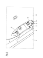
- Nachfolgend soll die Erfindung an einem Ausführungsbeispiel näher erläutert werden. In der beigefügten Zeichnung zeigt:
-
Figur 1 : einen schematischen Querschnitt durch eine Welle 1 mit Stopfbuchse, -
Figur 2 : eine Gesamtansicht und -
Figur 3 : einen Querschnitt durch einen Pulper. - Bei der Maschine handelt es sich gemäß
Figur 3 um einen Pulper zur Auflösung der Fasern und zur Bilder einer Faserstoffsuspension 11. Hierzu besitzt der noch oben offene Arbeitsraum 10 des Pulpers am Boden ein Behandlungselement 12 in Form eines antreibbaren Rotors. - Die erforderliche Antriebsleistung wird außerhalb des den Arbeitsraum 10 bildenden Gehäuses 8 von einem Antrieb 7 erbracht, der über eine rotierbar gelagerte Welle 1 mit dem Rotor im Arbeitsraum 10 verbunden ist.
- Anwendbar ist die Erfindung jedoch auch bei anderen Behandlungsmaschinen, beispielsweise bei einem Refiner, Disperger oder einem Sortierer. Je nach Art der Maschine kann das Behandlungselement 12 dann als Wendel, Mahlgarnitur o.ä. ausgebildet sein.
- Der Antrieb 7 kann dabei zur Drehzahlanpassung auch noch ein Getriebe umfassen.
- Wie in
Figur 1 zu erkennen, erfolgt die Abdichtung der rotierenden Welle 1 gegenüber dem Gehäuse 8 des Pulpers mit Hilfe einer Stopfbuchse. Wie allgemein bekannt, wird dabei eine dichtende Stopfbuchspackung 5 von einer flanschähnlichen Stopfbuchsbrille 4 mit Hilfe von Verstellmitteln 3, hier Schrauben axial verpresst. Durch die axiale Pressung entsteht auch eine radiale Pressung der Stopfbuchspackung 5 auf der Welle 1. Dadurch wird der Dichtspalt auf ein den Betriebsbedingungen angepasstes Minimum eingestellt. Eine geringe Leckage ist nicht gänzlich auszuschließen.
Die Verstellmittel 3 in Form achsparalleler Schrauben können hierbei zur Verstärkung der Anpressung der Stopfbuchspackung 5 (gegen einen Anschlag des Gehäuses 8) in das Gehäuse 8 gedreht werden. - Zwischen der Stopfbuchse und dem Antrieb 7, einem Getriebe oder einem Lager ist die Welle 1 über eine Frei-Strecke 9 normalerweise frei zugänglich. Dies erlaubt den Zugang zu den meist 4 bis 6 Verstellmitteln 3 der Stopfbuchse.
- Falls die Verstellmittel 3 bei rotierender Welle 1 verstellt werden, so besteht eine nicht unerhebliche Gefahr des Monteurs durch einen Kontakt mit der Welle 1.
Um dies zu verhindern, besitzt die Welle 1 im Bereich der Frei-Strecke 9 eine Schutzabdeckung 2 aus Edelstahl. Diese Schutzabdeckung 2 hat zur Welle 1 etwa einen Abstand zwischen 15 und 30 mm und eine axiale Länge zwischen 70 und 300 mm. - Des Weiteren ist die Schutzabdeckung 2 perforiert ausgebildet, so dass leckende Flüssigkeit aus der Schutzabdeckung 2 fließen und gesammelt werden kann. Hierzu befindet sich, wie in
Figur 2 dargestellt, unter der Schutzabdeckung 2 eine Auffangrinne 13 zur Aufnahme der aus der Schutzabdeckung 2 austretenden Flüssigkeit.
Außerdem ermöglicht die Perforation einen Temperaturausgleich mit der Umgebung, so dass es zu keiner Überhitzung kommen kann. - Um die Zugänglichkeit der Verstellmittel 3 gewährleisten zu können, befinden sich diese radial außerhalb der Schutzabdeckung 2.
- Die Befestigung der Schutzabdeckung 2 erfolgt über die Verstellmittel 3 selbst an der Brille 4 der Stopfbuchse. Zur Vereinfachung der Montage besitzt die Brille 4 Aussparungen 6 zur Justierung der Schutzabdeckung 2.
Bei dem hier gewählten Beispiel nehmen die Ausnehmungen 6 die Befestigungslaschen der Schutzabdeckung 2 auf, durch welche die Verstellmittel 3 geführt sind.
Claims (11)
- Maschine zur Behandlung einer Faserstoffsuspension (11) mit einem Arbeitsraum in den zumindest eine rotierbare Welle (1) mit wenigstens einem Behandlungselement (12) geführt ist, wobei die Welle (1) außerhalb des Arbeitsraumes (10) gegenüber dem Gehäuse (8) des Arbeitsraumes (10) mittels einer Stopfbuchse abgedichtet und an dem vom Arbeitsraum (10) weg gewandten Ende der Stopfbuchse über eine Frei-Strecke (9) ungestützt ist und Verstellmittel (3) zur Beeinflussung der Dichtwirkung der Stopfbuchse im Bereich der Frei-Strecke (9) vorhanden sind, dadurch gekennzeichnet, dass die Welle (1) im Bereich der Frei-Strecke (9) zumindest teilweise von einer an der Stopfbuchse befestigten Schutzabdeckung (2) umgeben ist.
- Maschine zur Behandlung einer Faserstoffsuspension (11) mit einem Arbeitsraum (10) in den zumindest eine rotierbare Welle (1) mit wenigstens einem Behandlungselement (12) geführt ist, wobei die Welle (1) außerhalb des Arbeitsraumes (10) gegenüber dem Gehäuse (8) des Arbeitsraumes (10) mittels einer Stopfbuchse abgedichtet und an dem vom Arbeitsraum (10) weg gewandten Ende der Stopfbuchse über eine Frei-Strecke (9) ungestützt ist und Verstellmittel (3) zur Beeinflussung der Dichtwirkung der Stopfbuchse im Bereich der Frei-Strecke (9) vorhanden sind, insbesondere nach Anspruch 1, dadurch gekennzeichnet, dass die Welle (1) im Bereich der Frei-Strecke (9) zumindest teilweise von einer Schutzabdeckung (2) umgeben ist und die Verstellmittel (3) der Stopfbuchse außerhalb der Schutzabdeckung (2) liegen.
- Maschine nach Anspruch 1 oder 2, dadurch gekennzeichnet, dass die Schutzabdeckung (2) an oder über die Verstellmittel (3) der Stopfbuchse fixiert ist.
- Maschine nach einem der vorhergehenden Ansprüche, dadurch gekennzeichnet, dass die Verstellmittel (3) der Stopfbuchse von Schrauben gebildet werden, die die Brille (4) der Stopfbuchse gegen die Stopfbuchspackung (5) pressen.
- Maschine nach einem der vorhergehenden Ansprüche, dadurch gekennzeichnet, dass die Brille (4) der Stopfbuchse Aussparungen (6) zur Justierung der Schutzabdeckung (2) besitzt.
- Maschine nach einem der vorhergehenden Ansprüche, dadurch gekennzeichnet, dass die Schutzabdeckung (2) perforiert ausgebildet ist.
- Maschine nach einem der vorhergehenden Ansprüche, dadurch gekennzeichnet, dass der Abstand zwischen der Welle (1) und der Schutzabdeckung (2) zwischen 2 und 100 mm, vorzugsweise zwischen 5 und 30 mm liegt.
- Maschine nach einem der vorhergehenden Ansprüche, dadurch gekennzeichnet, dass die axiale Länge der Schutzabdeckung (2) zwischen 25 und 500 mm, vorzugsweise zwischen 70 und 300 mm liegt.
- Maschine nach einem der vorhergehenden Ansprüche, dadurch gekennzeichnet, dass der Durchmesser der Welle (1) zwischen 20 und 500 mm, vorzugsweise zwischen 50 und 300 mm liegt.
- Maschine nach einem der vorhergehenden Ansprüche, dadurch gekennzeichnet, dass das Behandlungselement (12) von einem Rotor gebildet wird.
- Maschine nach einem der vorhergehenden Ansprüche, dadurch gekennzeichnet, dass diese als Pulper, Disperger, Refiner oder Sortierer ausgebildet ist.
Applications Claiming Priority (1)
| Application Number | Priority Date | Filing Date | Title |
|---|---|---|---|
| DE200910015902 DE102009015902A1 (de) | 2009-04-01 | 2009-04-01 | Maschine zur Behandlung einer Faserstoffsuspension |
Publications (3)
| Publication Number | Publication Date |
|---|---|
| EP2236866A2 true EP2236866A2 (de) | 2010-10-06 |
| EP2236866A3 EP2236866A3 (de) | 2011-02-23 |
| EP2236866B1 EP2236866B1 (de) | 2012-06-06 |
Family
ID=42341358
Family Applications (1)
| Application Number | Title | Priority Date | Filing Date |
|---|---|---|---|
| EP20100155407 Not-in-force EP2236866B1 (de) | 2009-04-01 | 2010-03-04 | Maschine zur Behandlung einer Fasersuspension |
Country Status (2)
| Country | Link |
|---|---|
| EP (1) | EP2236866B1 (de) |
| DE (1) | DE102009015902A1 (de) |
Family Cites Families (4)
| Publication number | Priority date | Publication date | Assignee | Title |
|---|---|---|---|---|
| DE843937C (de) * | 1943-09-28 | 1952-07-14 | Daimler Benz Ag | Dichtung, insbesondere Innendichtung in Gestalt eines axial eingespannten elastischen Ringes |
| JPS5248101U (de) * | 1975-10-02 | 1977-04-06 | ||
| CH613239A5 (de) * | 1976-10-19 | 1979-09-14 | Escher Wyss Gmbh | |
| DE29902431U1 (de) * | 1998-06-18 | 1999-07-15 | Voith Sulzer Papiertechnik Patent GmbH, 88213 Ravensburg | Auflöseorgan für einen Papierstofflöser |
-
2009
- 2009-04-01 DE DE200910015902 patent/DE102009015902A1/de not_active Withdrawn
-
2010
- 2010-03-04 EP EP20100155407 patent/EP2236866B1/de not_active Not-in-force
Non-Patent Citations (1)
| Title |
|---|
| None |
Also Published As
| Publication number | Publication date |
|---|---|
| EP2236866B1 (de) | 2012-06-06 |
| EP2236866A3 (de) | 2011-02-23 |
| DE102009015902A1 (de) | 2010-10-07 |
Similar Documents
| Publication | Publication Date | Title |
|---|---|---|
| DE112013000924B4 (de) | Labyrinthdichtung | |
| DE60212451T2 (de) | Aussenseitig befestigter spiraladapter | |
| DE102016012501C5 (de) | Getriebe, aufweisend eine Welle, ein Gehäuseteil und ein Adaptergehäuse | |
| EP3218663A1 (de) | Rotationswärmetauschereinrichtung | |
| DE102009025941A1 (de) | Dichtungssysteme für Rotationsmaschinen und Verfahren für deren Veränderung | |
| DE102014011228B4 (de) | Elektrische Maschine | |
| EP2236866B1 (de) | Maschine zur Behandlung einer Fasersuspension | |
| DE102012005390A1 (de) | Spinnvorrichtung | |
| EP0485876A2 (de) | Stopfbuchse | |
| DE69112614T2 (de) | Wellendichtung. | |
| DE102006060382A1 (de) | Vorrichtung zur Störungsfrüherkennung an Maschinen und/oder deren Bauteilen | |
| WO2010020382A2 (de) | Presswalzenanordnung und presswalze | |
| WO2013071996A1 (de) | Druckgekapseltes pumpengehäuse | |
| DE102004028670A1 (de) | Walzenlagerung bei einer Rollenpresse | |
| WO2022199984A1 (de) | Anordnung zur abdichtung einer rotorwelle einer e-maschine, e-maschine und antriebsvorrichtung | |
| EP3461937B1 (de) | Offenend-spinneinrichtung | |
| DE102006052763A1 (de) | Direktantrieb | |
| EP1749922B1 (de) | Vorrichtung zur Verarbeitung einer Faserstoffsuspension und Plattensegment zur Verwendung in einer solchen Vorrichtung | |
| DE19904761A1 (de) | Vorrichtung zum Abdichten einer Papierstoffsuspension an einer Wellendurchführung | |
| EP3467319B1 (de) | Kreiselpumpe mit verbesserter saughalsdichtung | |
| DE19910279A1 (de) | Lagerung eines Spinnrotors einer Offenend-Spinnvorrichtung | |
| EP2853019B1 (de) | Elektrische maschine | |
| DE102008032921A1 (de) | Lagersystem | |
| EP1593818B1 (de) | Turbomaschine mit einem hydrodynamischen und einem hydrostatischen Axiallager | |
| EP4114572A1 (de) | Faserbehandlungsvorrichtung |
Legal Events
| Date | Code | Title | Description |
|---|---|---|---|
| PUAI | Public reference made under article 153(3) epc to a published international application that has entered the european phase |
Free format text: ORIGINAL CODE: 0009012 |
|
| AK | Designated contracting states |
Kind code of ref document: A2 Designated state(s): AT BE BG CH CY CZ DE DK EE ES FI FR GB GR HR HU IE IS IT LI LT LU LV MC MK MT NL NO PL PT RO SE SI SK SM TR |
|
| AX | Request for extension of the european patent |
Extension state: AL BA ME RS |
|
| PUAL | Search report despatched |
Free format text: ORIGINAL CODE: 0009013 |
|
| AK | Designated contracting states |
Kind code of ref document: A3 Designated state(s): AT BE BG CH CY CZ DE DK EE ES FI FR GB GR HR HU IE IS IT LI LT LU LV MC MK MT NL NO PL PT RO SE SI SK SM TR |
|
| AX | Request for extension of the european patent |
Extension state: AL BA ME RS |
|
| 17P | Request for examination filed |
Effective date: 20110823 |
|
| GRAP | Despatch of communication of intention to grant a patent |
Free format text: ORIGINAL CODE: EPIDOSNIGR1 |
|
| GRAS | Grant fee paid |
Free format text: ORIGINAL CODE: EPIDOSNIGR3 |
|
| GRAA | (expected) grant |
Free format text: ORIGINAL CODE: 0009210 |
|
| AK | Designated contracting states |
Kind code of ref document: B1 Designated state(s): AT BE BG CH CY CZ DE DK EE ES FI FR GB GR HR HU IE IS IT LI LT LU LV MC MK MT NL NO PL PT RO SE SI SK SM TR |
|
| REG | Reference to a national code |
Ref country code: GB Ref legal event code: FG4D Free format text: NOT ENGLISH |
|
| REG | Reference to a national code |
Ref country code: AT Ref legal event code: REF Ref document number: 561197 Country of ref document: AT Kind code of ref document: T Effective date: 20120615 Ref country code: CH Ref legal event code: EP |
|
| REG | Reference to a national code |
Ref country code: IE Ref legal event code: FG4D Free format text: LANGUAGE OF EP DOCUMENT: GERMAN |
|
| REG | Reference to a national code |
Ref country code: DE Ref legal event code: R096 Ref document number: 502010000848 Country of ref document: DE Effective date: 20120809 |
|
| REG | Reference to a national code |
Ref country code: NL Ref legal event code: VDEP Effective date: 20120606 |
|
| PG25 | Lapsed in a contracting state [announced via postgrant information from national office to epo] |
Ref country code: NO Free format text: LAPSE BECAUSE OF FAILURE TO SUBMIT A TRANSLATION OF THE DESCRIPTION OR TO PAY THE FEE WITHIN THE PRESCRIBED TIME-LIMIT Effective date: 20120906 Ref country code: SE Free format text: LAPSE BECAUSE OF FAILURE TO SUBMIT A TRANSLATION OF THE DESCRIPTION OR TO PAY THE FEE WITHIN THE PRESCRIBED TIME-LIMIT Effective date: 20120606 Ref country code: FI Free format text: LAPSE BECAUSE OF FAILURE TO SUBMIT A TRANSLATION OF THE DESCRIPTION OR TO PAY THE FEE WITHIN THE PRESCRIBED TIME-LIMIT Effective date: 20120606 Ref country code: CY Free format text: LAPSE BECAUSE OF FAILURE TO SUBMIT A TRANSLATION OF THE DESCRIPTION OR TO PAY THE FEE WITHIN THE PRESCRIBED TIME-LIMIT Effective date: 20120606 Ref country code: LT Free format text: LAPSE BECAUSE OF FAILURE TO SUBMIT A TRANSLATION OF THE DESCRIPTION OR TO PAY THE FEE WITHIN THE PRESCRIBED TIME-LIMIT Effective date: 20120606 |
|
| REG | Reference to a national code |
Ref country code: LT Ref legal event code: MG4D Effective date: 20120606 |
|
| PG25 | Lapsed in a contracting state [announced via postgrant information from national office to epo] |
Ref country code: LV Free format text: LAPSE BECAUSE OF FAILURE TO SUBMIT A TRANSLATION OF THE DESCRIPTION OR TO PAY THE FEE WITHIN THE PRESCRIBED TIME-LIMIT Effective date: 20120606 Ref country code: HR Free format text: LAPSE BECAUSE OF FAILURE TO SUBMIT A TRANSLATION OF THE DESCRIPTION OR TO PAY THE FEE WITHIN THE PRESCRIBED TIME-LIMIT Effective date: 20120606 Ref country code: GR Free format text: LAPSE BECAUSE OF FAILURE TO SUBMIT A TRANSLATION OF THE DESCRIPTION OR TO PAY THE FEE WITHIN THE PRESCRIBED TIME-LIMIT Effective date: 20120907 Ref country code: SI Free format text: LAPSE BECAUSE OF FAILURE TO SUBMIT A TRANSLATION OF THE DESCRIPTION OR TO PAY THE FEE WITHIN THE PRESCRIBED TIME-LIMIT Effective date: 20120606 |
|
| PG25 | Lapsed in a contracting state [announced via postgrant information from national office to epo] |
Ref country code: NL Free format text: LAPSE BECAUSE OF FAILURE TO SUBMIT A TRANSLATION OF THE DESCRIPTION OR TO PAY THE FEE WITHIN THE PRESCRIBED TIME-LIMIT Effective date: 20120606 Ref country code: IS Free format text: LAPSE BECAUSE OF FAILURE TO SUBMIT A TRANSLATION OF THE DESCRIPTION OR TO PAY THE FEE WITHIN THE PRESCRIBED TIME-LIMIT Effective date: 20121006 Ref country code: RO Free format text: LAPSE BECAUSE OF FAILURE TO SUBMIT A TRANSLATION OF THE DESCRIPTION OR TO PAY THE FEE WITHIN THE PRESCRIBED TIME-LIMIT Effective date: 20120606 Ref country code: EE Free format text: LAPSE BECAUSE OF FAILURE TO SUBMIT A TRANSLATION OF THE DESCRIPTION OR TO PAY THE FEE WITHIN THE PRESCRIBED TIME-LIMIT Effective date: 20120606 Ref country code: SK Free format text: LAPSE BECAUSE OF FAILURE TO SUBMIT A TRANSLATION OF THE DESCRIPTION OR TO PAY THE FEE WITHIN THE PRESCRIBED TIME-LIMIT Effective date: 20120606 Ref country code: CZ Free format text: LAPSE BECAUSE OF FAILURE TO SUBMIT A TRANSLATION OF THE DESCRIPTION OR TO PAY THE FEE WITHIN THE PRESCRIBED TIME-LIMIT Effective date: 20120606 |
|
| PG25 | Lapsed in a contracting state [announced via postgrant information from national office to epo] |
Ref country code: PT Free format text: LAPSE BECAUSE OF FAILURE TO SUBMIT A TRANSLATION OF THE DESCRIPTION OR TO PAY THE FEE WITHIN THE PRESCRIBED TIME-LIMIT Effective date: 20121008 Ref country code: PL Free format text: LAPSE BECAUSE OF FAILURE TO SUBMIT A TRANSLATION OF THE DESCRIPTION OR TO PAY THE FEE WITHIN THE PRESCRIBED TIME-LIMIT Effective date: 20120606 Ref country code: IT Free format text: LAPSE BECAUSE OF FAILURE TO SUBMIT A TRANSLATION OF THE DESCRIPTION OR TO PAY THE FEE WITHIN THE PRESCRIBED TIME-LIMIT Effective date: 20120606 |
|
| PLBE | No opposition filed within time limit |
Free format text: ORIGINAL CODE: 0009261 |
|
| STAA | Information on the status of an ep patent application or granted ep patent |
Free format text: STATUS: NO OPPOSITION FILED WITHIN TIME LIMIT |
|
| PG25 | Lapsed in a contracting state [announced via postgrant information from national office to epo] |
Ref country code: DK Free format text: LAPSE BECAUSE OF FAILURE TO SUBMIT A TRANSLATION OF THE DESCRIPTION OR TO PAY THE FEE WITHIN THE PRESCRIBED TIME-LIMIT Effective date: 20120606 Ref country code: ES Free format text: LAPSE BECAUSE OF FAILURE TO SUBMIT A TRANSLATION OF THE DESCRIPTION OR TO PAY THE FEE WITHIN THE PRESCRIBED TIME-LIMIT Effective date: 20120917 |
|
| PGFP | Annual fee paid to national office [announced via postgrant information from national office to epo] |
Ref country code: DE Payment date: 20130321 Year of fee payment: 4 |
|
| 26N | No opposition filed |
Effective date: 20130307 |
|
| REG | Reference to a national code |
Ref country code: DE Ref legal event code: R097 Ref document number: 502010000848 Country of ref document: DE Effective date: 20130307 |
|
| PG25 | Lapsed in a contracting state [announced via postgrant information from national office to epo] |
Ref country code: BG Free format text: LAPSE BECAUSE OF FAILURE TO SUBMIT A TRANSLATION OF THE DESCRIPTION OR TO PAY THE FEE WITHIN THE PRESCRIBED TIME-LIMIT Effective date: 20120906 |
|
| BERE | Be: lapsed |
Owner name: VOITH PATENT G.M.B.H. Effective date: 20130331 |
|
| PG25 | Lapsed in a contracting state [announced via postgrant information from national office to epo] |
Ref country code: MC Free format text: LAPSE BECAUSE OF NON-PAYMENT OF DUE FEES Effective date: 20130331 |
|
| REG | Reference to a national code |
Ref country code: FR Ref legal event code: ST Effective date: 20131129 |
|
| REG | Reference to a national code |
Ref country code: IE Ref legal event code: MM4A |
|
| PG25 | Lapsed in a contracting state [announced via postgrant information from national office to epo] |
Ref country code: BE Free format text: LAPSE BECAUSE OF NON-PAYMENT OF DUE FEES Effective date: 20130331 Ref country code: FR Free format text: LAPSE BECAUSE OF NON-PAYMENT OF DUE FEES Effective date: 20130402 Ref country code: IE Free format text: LAPSE BECAUSE OF NON-PAYMENT OF DUE FEES Effective date: 20130304 |
|
| PG25 | Lapsed in a contracting state [announced via postgrant information from national office to epo] |
Ref country code: MT Free format text: LAPSE BECAUSE OF FAILURE TO SUBMIT A TRANSLATION OF THE DESCRIPTION OR TO PAY THE FEE WITHIN THE PRESCRIBED TIME-LIMIT Effective date: 20120606 |
|
| REG | Reference to a national code |
Ref country code: DE Ref legal event code: R119 Ref document number: 502010000848 Country of ref document: DE |
|
| REG | Reference to a national code |
Ref country code: CH Ref legal event code: PL |
|
| GBPC | Gb: european patent ceased through non-payment of renewal fee |
Effective date: 20140304 |
|
| REG | Reference to a national code |
Ref country code: DE Ref legal event code: R119 Ref document number: 502010000848 Country of ref document: DE Effective date: 20141001 |
|
| PG25 | Lapsed in a contracting state [announced via postgrant information from national office to epo] |
Ref country code: CH Free format text: LAPSE BECAUSE OF NON-PAYMENT OF DUE FEES Effective date: 20140331 Ref country code: GB Free format text: LAPSE BECAUSE OF NON-PAYMENT OF DUE FEES Effective date: 20140304 Ref country code: LI Free format text: LAPSE BECAUSE OF NON-PAYMENT OF DUE FEES Effective date: 20140331 Ref country code: DE Free format text: LAPSE BECAUSE OF NON-PAYMENT OF DUE FEES Effective date: 20141001 |
|
| PG25 | Lapsed in a contracting state [announced via postgrant information from national office to epo] |
Ref country code: SM Free format text: LAPSE BECAUSE OF FAILURE TO SUBMIT A TRANSLATION OF THE DESCRIPTION OR TO PAY THE FEE WITHIN THE PRESCRIBED TIME-LIMIT Effective date: 20120606 |
|
| PG25 | Lapsed in a contracting state [announced via postgrant information from national office to epo] |
Ref country code: TR Free format text: LAPSE BECAUSE OF FAILURE TO SUBMIT A TRANSLATION OF THE DESCRIPTION OR TO PAY THE FEE WITHIN THE PRESCRIBED TIME-LIMIT Effective date: 20120606 |
|
| PG25 | Lapsed in a contracting state [announced via postgrant information from national office to epo] |
Ref country code: MK Free format text: LAPSE BECAUSE OF FAILURE TO SUBMIT A TRANSLATION OF THE DESCRIPTION OR TO PAY THE FEE WITHIN THE PRESCRIBED TIME-LIMIT Effective date: 20120606 Ref country code: HU Free format text: LAPSE BECAUSE OF FAILURE TO SUBMIT A TRANSLATION OF THE DESCRIPTION OR TO PAY THE FEE WITHIN THE PRESCRIBED TIME-LIMIT; INVALID AB INITIO Effective date: 20100304 Ref country code: LU Free format text: LAPSE BECAUSE OF NON-PAYMENT OF DUE FEES Effective date: 20130304 |
|
| REG | Reference to a national code |
Ref country code: AT Ref legal event code: MM01 Ref document number: 561197 Country of ref document: AT Kind code of ref document: T Effective date: 20150304 |
|
| PG25 | Lapsed in a contracting state [announced via postgrant information from national office to epo] |
Ref country code: AT Free format text: LAPSE BECAUSE OF NON-PAYMENT OF DUE FEES Effective date: 20150304 |