EP2236808A2 - Fuel system for a direct injection engine - Google Patents
Fuel system for a direct injection engine Download PDFInfo
- Publication number
- EP2236808A2 EP2236808A2 EP10153878A EP10153878A EP2236808A2 EP 2236808 A2 EP2236808 A2 EP 2236808A2 EP 10153878 A EP10153878 A EP 10153878A EP 10153878 A EP10153878 A EP 10153878A EP 2236808 A2 EP2236808 A2 EP 2236808A2
- Authority
- EP
- European Patent Office
- Prior art keywords
- fuel
- rails
- fuel rail
- rail
- engine block
- Prior art date
- Legal status (The legal status is an assumption and is not a legal conclusion. Google has not performed a legal analysis and makes no representation as to the accuracy of the status listed.)
- Granted
Links
Images


Classifications
-
- F—MECHANICAL ENGINEERING; LIGHTING; HEATING; WEAPONS; BLASTING
- F02—COMBUSTION ENGINES; HOT-GAS OR COMBUSTION-PRODUCT ENGINE PLANTS
- F02M—SUPPLYING COMBUSTION ENGINES IN GENERAL WITH COMBUSTIBLE MIXTURES OR CONSTITUENTS THEREOF
- F02M55/00—Fuel-injection apparatus characterised by their fuel conduits or their venting means; Arrangements of conduits between fuel tank and pump F02M37/00
- F02M55/02—Conduits between injection pumps and injectors, e.g. conduits between pump and common-rail or conduits between common-rail and injectors
- F02M55/025—Common rails
-
- F—MECHANICAL ENGINEERING; LIGHTING; HEATING; WEAPONS; BLASTING
- F02—COMBUSTION ENGINES; HOT-GAS OR COMBUSTION-PRODUCT ENGINE PLANTS
- F02M—SUPPLYING COMBUSTION ENGINES IN GENERAL WITH COMBUSTIBLE MIXTURES OR CONSTITUENTS THEREOF
- F02M63/00—Other fuel-injection apparatus having pertinent characteristics not provided for in groups F02M39/00 - F02M57/00 or F02M67/00; Details, component parts, or accessories of fuel-injection apparatus, not provided for in, or of interest apart from, the apparatus of groups F02M39/00 - F02M61/00 or F02M67/00; Combination of fuel pump with other devices, e.g. lubricating oil pump
- F02M63/02—Fuel-injection apparatus having several injectors fed by a common pumping element, or having several pumping elements feeding a common injector; Fuel-injection apparatus having provisions for cutting-out pumps, pumping elements, or injectors; Fuel-injection apparatus having provisions for variably interconnecting pumping elements and injectors alternatively
- F02M63/0225—Fuel-injection apparatus having a common rail feeding several injectors ; Means for varying pressure in common rails; Pumps feeding common rails
-
- F—MECHANICAL ENGINEERING; LIGHTING; HEATING; WEAPONS; BLASTING
- F02—COMBUSTION ENGINES; HOT-GAS OR COMBUSTION-PRODUCT ENGINE PLANTS
- F02M—SUPPLYING COMBUSTION ENGINES IN GENERAL WITH COMBUSTIBLE MIXTURES OR CONSTITUENTS THEREOF
- F02M63/00—Other fuel-injection apparatus having pertinent characteristics not provided for in groups F02M39/00 - F02M57/00 or F02M67/00; Details, component parts, or accessories of fuel-injection apparatus, not provided for in, or of interest apart from, the apparatus of groups F02M39/00 - F02M61/00 or F02M67/00; Combination of fuel pump with other devices, e.g. lubricating oil pump
- F02M63/02—Fuel-injection apparatus having several injectors fed by a common pumping element, or having several pumping elements feeding a common injector; Fuel-injection apparatus having provisions for cutting-out pumps, pumping elements, or injectors; Fuel-injection apparatus having provisions for variably interconnecting pumping elements and injectors alternatively
- F02M63/0225—Fuel-injection apparatus having a common rail feeding several injectors ; Means for varying pressure in common rails; Pumps feeding common rails
- F02M63/0275—Arrangement of common rails
-
- F—MECHANICAL ENGINEERING; LIGHTING; HEATING; WEAPONS; BLASTING
- F02—COMBUSTION ENGINES; HOT-GAS OR COMBUSTION-PRODUCT ENGINE PLANTS
- F02M—SUPPLYING COMBUSTION ENGINES IN GENERAL WITH COMBUSTIBLE MIXTURES OR CONSTITUENTS THEREOF
- F02M63/00—Other fuel-injection apparatus having pertinent characteristics not provided for in groups F02M39/00 - F02M57/00 or F02M67/00; Details, component parts, or accessories of fuel-injection apparatus, not provided for in, or of interest apart from, the apparatus of groups F02M39/00 - F02M61/00 or F02M67/00; Combination of fuel pump with other devices, e.g. lubricating oil pump
- F02M63/02—Fuel-injection apparatus having several injectors fed by a common pumping element, or having several pumping elements feeding a common injector; Fuel-injection apparatus having provisions for cutting-out pumps, pumping elements, or injectors; Fuel-injection apparatus having provisions for variably interconnecting pumping elements and injectors alternatively
- F02M63/0225—Fuel-injection apparatus having a common rail feeding several injectors ; Means for varying pressure in common rails; Pumps feeding common rails
- F02M63/0275—Arrangement of common rails
- F02M63/0285—Arrangement of common rails having more than one common rail
-
- F—MECHANICAL ENGINEERING; LIGHTING; HEATING; WEAPONS; BLASTING
- F02—COMBUSTION ENGINES; HOT-GAS OR COMBUSTION-PRODUCT ENGINE PLANTS
- F02M—SUPPLYING COMBUSTION ENGINES IN GENERAL WITH COMBUSTIBLE MIXTURES OR CONSTITUENTS THEREOF
- F02M2200/00—Details of fuel-injection apparatus, not otherwise provided for
- F02M2200/30—Fuel-injection apparatus having mechanical parts, the movement of which is damped
- F02M2200/306—Fuel-injection apparatus having mechanical parts, the movement of which is damped using mechanical means
Definitions
- the present invention relates generally to direct injection internal combustion engines and, more particularly, to a fuel system for such engines which reduces the stress imposed on the fuel system components.
- Direct injection internal combustion engines are becoming increasingly popular in the automotive industry due in large part to their high efficiency and fuel economy.
- at least one fuel injector is mounted in a bore formed in the engine block which is open directly to the internal combustion chamber.
- a high pressure fuel rail is coupled to the fuel injector which, when open under control of the engine control unit, injects fuel directly into the internal combustion engine.
- the fuel in the fuel rails must necessarily be maintained at a relatively high pressure.
- a cam driven piston pump is used to pressurize the fuel rail.
- the present invention provides a device for reducing movement of the fuel rails in a direct injection fuel engine thereby reducing mechanical stress on those components.
- the present invention provides several different approaches for reducing movement of the fuel rail in the fuel system.
- a clamp extends across and is secured to both side by side fuel rails. By clamping the rails together, movement of the rails relative to the other fuel system components is reduced.
- the fuel rails may be either rigidly clamped together or may be resiliently clamped together with an elastomeric member.
- a moving mass is attached to the fuel rails with a resilient member. Consequently, movement of the moving mass opposes any movement of the rails thus effectively canceling the movement of the rails during operation of the fuel system.
- a flexible fluid conduit fluidly connects the fuel rails to the fuel injectors. This flexible fluid conduit thus reduces or altogether eliminates movement of the fuel rails caused by movement of the fuel injectors.
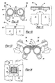
- FIG. 1 is a prior art diagrammatic view of a direct injection internal combustion engine
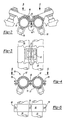
- FIG. 2 is a diagrammatic end view illustrating a first preferred embodiment of the present invention
- FIG. 3 is a view taken along line 3-3 in FIG. 2 ;
- FIG. 4 is a view similar to FIG. 2 , but illustrating a modification thereof;
- FIG. 5 is a view taken along line 5-5 in FIG. 4 ;
- FIG. 6 is a view similar to FIG. 2 , but illustrating a modification thereof
- FIG. 7 is a view taken along line 7-7 in FIG. 6 ;
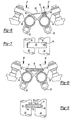
- FIG. 8 is a view similar to FIG. 2 , but illustrating a modification thereof
- FIG. 9 is a view taken along line 9-9 in FIG. 8 ;
- FIG. 10 is a view similar to FIG. 2 , but illustrating a modification thereof;
- FIG. 11 is an exploded fragmentary top view of the fuel rails of FIG. 10 ;
- FIG. 12 is a view taken substantially along line 12-12 in FIG. 10 ;
- FIG. 13 is a view similar to FIG. 2 , but illustrating a modification thereof;
- FIG. 14 is a view taken along line 14-14 in FIG. 13 ;
- FIG. 15 is a side view illustrating a further embodiment of the present invention.
- FIG. 16 is a view taken along line 16-16 in FIG. 15 .
- the engine 20 includes an engine block 22 having a plurality of engine combustion chambers 24 in which pistons (not shown) are reciprocally mounted.
- At least one fuel injector 26 is associated with each combustion chamber 24.
- Each fuel injector 26 is positioned within a fuel injector bore 28 formed in the engine block 22 which is open to the combustion chambers 24.
- Each fuel injector 26, furthermore, is then fluidly coupled to a fuel rail 30 having an internal fuel chamber 32.
- a high pressure fuel pump (not shown) provides pressurized fuel to the fuel rail chambers 32 which, in turn, supply that pressurized fuel to the injectors 26.
- the fuel injectors illustrated in FIG. 1 are for a V engine in which two fuel rails 30 are positioned side by side each other.
- the fuel injectors 26 are rigidly secured to their associated fuel rail 30. Upon each injection of fuel, the fuel injector 26 moves slightly away from the combustion chamber 24 which causes a like movement in its associated fuel rail 30. Such movement of the fuel rail 30 in turn imparts mechanical stress on the fuel system components.
- a V-shaped clamp 40 extends between and is attached to each fuel rail 30 by fasteners 42 ( FIG. 3 ). Any conventional fastener 42 may be used to secure the clamp 40 to the fuel rails 30. Alternatively, the clamp 40 may be fixedly secured to the fuel rails 30 by welding or the like.
- a moving mass 44 is also secured to the clamp 40 by a resilient member or spring 46.
- the resilient member 46 allows the moving mass 44 to move relative to the clamp 40 and thus relative to the fuel rails 30.
- the moving mass 44 moves thus effectively canceling any movement of the fuel rails 30.
- the clamp 40 itself alone reduces movement of the fuel rails 30 during operation of the internal combustion engine.
- the moving mass 44 may also be used with a single fuel rail. In such a system, the moving mass 44 offsets or cancels movement of the fuel rail during operation of the engine.
- a clamp 50 extends around both fuel rails 30 and secures the fuel rails 30 together against movement.
- the clamp 50 may take any form, as shown the clamp 50 includes a top half 52 and a bottom half 54 which, together, encircle the fuel rails 30. These clamp halves 52 and 54 are secured together by fasteners 56 which may be any conventional fastener, such as a bolt and nut.
- the clamp 50 by rigidly securing the fuel rails 30 together, reduces movement of the fuel rails 30 and the resultant mechanical stress on the fuel system components from such movement.
- an elongated clamp 60 in the form of a strap has one end 62 rigidly secured to one fuel rail 30 in any conventional manner, such as by soldering.
- a second end 64 of the clamp 60 is then secured to the other fuel rail 30 by a fastener 66 which sandwiches an elastomeric resilient member 68 in between the fastener 66 and the fuel rail 30.
- the elastomeric dampener 68 dampens vibrations and movement of the fuel rails 30.
- an elongated resilient dampener 70 extends between the two fuel rails 30.
- a fastener 72 secures one end of the dampener 70 to one fuel rail 30 while a second fastener 74 secures the other end of the dampener 70 to the other fuel rail 30.
- the fastener 72 may comprise a bolt extending through the dampener 70 while the second fastener 74 is a nut that threadably engages the fastener 72.
- the fastener 72 also extends through a bolt stop 76 mounted to each fuel rail 30.
- the dampener 70 dampens vibrations of the fuel rails 30 in a lateral direction as indicated by arrows 78 in FIG. 9 .
- the dampener 70 effectively reduces movement of the fuel rail and likewise reduces component stress resulting from that movement.
- FIGS. 10-12 a still further embodiment of the present invention is shown in which a clamp 80 having two clamp sections 82 and 84 is provided to minimize movement of the fuel rails 30.
- Each clamp section 82 and 84 includes a recess 86 which corresponds in shape to a portion of the ends 88 of the fuel rails 30.
- a fastener 90 secures the clamp sections 82 and 84 together while simultaneously compressing the clamp sections 82 and 84 around the ends 88 of the fuel rails 30. In doing so, the fuel rails 30 are rigidly secured together against movement thus reducing mechanical stress on the fuel system components.
- a still further embodiment of the present invention is shown in which a generally V-shaped clamp 100 extends between and is secured to both fuel rails 30. Any conventional means, such as fasteners, solder or the like, may be used to secure the clamp 100 rigidly to the fuel rails 30.
- a resilient member 102 preferably constructed of an elastomeric material, is disposed across the top of the clamp 100.
- a moving mass 104 is then positioned within the resilient member 102 so that the resilient member 102 is sandwiched in between the moving mass 104 and the clamp 100.
- the resilient member 102 allows the moving mass 104 to move slightly relative to the fuel rails 30.
- the moving mass 104 by moving, dampens the movement of the rails 30 and reduces component stress.
- FIGS. 15 and 16 a still further embodiment of the present invention is shown in which the fuel injector 26 is fluidly connected to its associated fuel rail 30 by a flexible fluid conduit 110.
- the fluid conduit 110 may be in the shape of a flexible bellows although other shapes may alternatively be used.
- movement of the fuel injector 26 in response to a fuel injection by the injector 26 merely causes the fluid conduit 110 to flex, thus isolating any vibration of the fuel injector 26 from the fuel rail 30. In doing so, movement of the fuel rail 30 is greatly reduced, if not altogether eliminated, thus reducing mechanical stress caused by movement of the fuel rail 30.
- a locator 120 is externally threaded and includes a radially inwardly projecting tab 122.
- the locator 120 is preferably made of a non-metallic material to eliminate metal-to-metal contact between the injector 26 and the engine block 20 to dampen noise.
- the injector bore 28 includes an internally threaded portion 126 at its outer end. Consequently, by threadably securing the locator to the engine block 20, the locator 120 simply, but effectively, locks the fuel injector 26 against axial movement relative to the engine block.
- the fuel injector 26 can be made of a non-metallic material with the threads to engage the thread portion 126 on the engine block formed integrally on the fuel injector 26.
- the present invention provides several different devices for reducing, or altogether eliminating, movement of the fuel rail relative to the engine block. Stress on the fuel system components resulting from movement of the fuel rail relative to the engine block during operation of the internal combustion engine is substantially reduced.
Landscapes
- Engineering & Computer Science (AREA)
- Chemical & Material Sciences (AREA)
- Combustion & Propulsion (AREA)
- Mechanical Engineering (AREA)
- General Engineering & Computer Science (AREA)
- Fuel-Injection Apparatus (AREA)
Abstract
Description
- The present invention relates generally to direct injection internal combustion engines and, more particularly, to a fuel system for such engines which reduces the stress imposed on the fuel system components.
- Direct injection internal combustion engines are becoming increasingly popular in the automotive industry due in large part to their high efficiency and fuel economy. In such a direct injection engine, at least one fuel injector is mounted in a bore formed in the engine block which is open directly to the internal combustion chamber. A high pressure fuel rail is coupled to the fuel injector which, when open under control of the engine control unit, injects fuel directly into the internal combustion engine.
- Since the injectors of the direct injection engine are open directly to the internal combustion chamber, the fuel in the fuel rails must necessarily be maintained at a relatively high pressure. Typically, a cam driven piston pump is used to pressurize the fuel rail.
- One disadvantage of direct injection internal combustion engines, however, is that the fuel system components move slightly relative to each other in response to the high pressure fuel injection pulses and pump pulses. This, in turn, imparts stress on the fuel system components which can result in cracking or other component failure.
- The present invention provides a device for reducing movement of the fuel rails in a direct injection fuel engine thereby reducing mechanical stress on those components.
- In brief, the present invention provides several different approaches for reducing movement of the fuel rail in the fuel system. In one embodiment of the invention, a clamp extends across and is secured to both side by side fuel rails. By clamping the rails together, movement of the rails relative to the other fuel system components is reduced. Furthermore, the fuel rails may be either rigidly clamped together or may be resiliently clamped together with an elastomeric member.
- In another form of the invention, a moving mass is attached to the fuel rails with a resilient member. Consequently, movement of the moving mass opposes any movement of the rails thus effectively canceling the movement of the rails during operation of the fuel system.
- In still another embodiment of the invention, a flexible fluid conduit fluidly connects the fuel rails to the fuel injectors. This flexible fluid conduit thus reduces or altogether eliminates movement of the fuel rails caused by movement of the fuel injectors.
- A better understanding of the present invention will be had upon reference to the following detailed description when read in conjunction with the accompanying drawing, wherein like reference characters refer to like parts throughout the several views, and in which:
-
FIG. 1 is a prior art diagrammatic view of a direct injection internal combustion engine; -
FIG. 2 is a diagrammatic end view illustrating a first preferred embodiment of the present invention; -
FIG. 3 is a view taken along line 3-3 inFIG. 2 ; -
FIG. 4 is a view similar toFIG. 2 , but illustrating a modification thereof; -
FIG. 5 is a view taken along line 5-5 inFIG. 4 ; -
FIG. 6 is a view similar toFIG. 2 , but illustrating a modification thereof; -
FIG. 7 is a view taken along line 7-7 inFIG. 6 ; -
FIG. 8 is a view similar toFIG. 2 , but illustrating a modification thereof; -
FIG. 9 is a view taken along line 9-9 inFIG. 8 ; -
FIG. 10 is a view similar toFIG. 2 , but illustrating a modification thereof; -
FIG. 11 is an exploded fragmentary top view of the fuel rails ofFIG. 10 ; -
FIG. 12 is a view taken substantially along line 12-12 inFIG. 10 ; -
FIG. 13 is a view similar toFIG. 2 , but illustrating a modification thereof; -
FIG. 14 is a view taken along line 14-14 inFIG. 13 ; -
FIG. 15 is a side view illustrating a further embodiment of the present invention; and -
FIG. 16 is a view taken along line 16-16 inFIG. 15 . - With reference first to
FIG. 1 , a portion of a prior art direct injectioninternal combustion engine 20 is shown diagrammatically. Theengine 20 includes anengine block 22 having a plurality ofengine combustion chambers 24 in which pistons (not shown) are reciprocally mounted. - At least one
fuel injector 26 is associated with eachcombustion chamber 24. Eachfuel injector 26 is positioned within afuel injector bore 28 formed in theengine block 22 which is open to thecombustion chambers 24. Eachfuel injector 26, furthermore, is then fluidly coupled to afuel rail 30 having aninternal fuel chamber 32. A high pressure fuel pump (not shown) provides pressurized fuel to thefuel rail chambers 32 which, in turn, supply that pressurized fuel to theinjectors 26. Furthermore, the fuel injectors illustrated inFIG. 1 are for a V engine in which twofuel rails 30 are positioned side by side each other. - Typically, the
fuel injectors 26 are rigidly secured to their associatedfuel rail 30. Upon each injection of fuel, thefuel injector 26 moves slightly away from thecombustion chamber 24 which causes a like movement in its associatedfuel rail 30. Such movement of thefuel rail 30 in turn imparts mechanical stress on the fuel system components. - With reference now to
FIGS. 2 and 3 , in order to reduce the movement of thefuel rails 30 relative to the engine block, a V-shaped clamp 40 extends between and is attached to eachfuel rail 30 by fasteners 42 (FIG. 3 ). Anyconventional fastener 42 may be used to secure theclamp 40 to thefuel rails 30. Alternatively, theclamp 40 may be fixedly secured to thefuel rails 30 by welding or the like. - A moving mass 44 is also secured to the
clamp 40 by a resilient member orspring 46. Theresilient member 46 allows the moving mass 44 to move relative to theclamp 40 and thus relative to thefuel rails 30. - In operation, as the fuel injectors impart movement to their associated
fuel rails 30, the moving mass 44 moves thus effectively canceling any movement of thefuel rails 30. Furthermore, theclamp 40 itself alone reduces movement of thefuel rails 30 during operation of the internal combustion engine. - Although two
fuel rails 30 are indicated inFIGS. 2 and 3 , it will be understood, of course, that the moving mass 44 may also be used with a single fuel rail. In such a system, the moving mass 44 offsets or cancels movement of the fuel rail during operation of the engine. - With reference now to
FIGS. 4 and 5 , a still further embodiment of the invention is illustrated in which aclamp 50 extends around bothfuel rails 30 and secures thefuel rails 30 together against movement. Although theclamp 50 may take any form, as shown theclamp 50 includes atop half 52 and abottom half 54 which, together, encircle thefuel rails 30. Theseclamp halves fasteners 56 which may be any conventional fastener, such as a bolt and nut. - In practice, the
clamp 50, by rigidly securing thefuel rails 30 together, reduces movement of thefuel rails 30 and the resultant mechanical stress on the fuel system components from such movement. - With reference now to
FIGS. 6 and 7 , a still further embodiment of the present invention is shown in which anelongated clamp 60 in the form of a strap has oneend 62 rigidly secured to onefuel rail 30 in any conventional manner, such as by soldering. Asecond end 64 of theclamp 60 is then secured to theother fuel rail 30 by afastener 66 which sandwiches an elastomericresilient member 68 in between thefastener 66 and thefuel rail 30. In practice, theelastomeric dampener 68 dampens vibrations and movement of the fuel rails 30. - With reference now to
FIGS. 8 and 9 , a still further embodiment of the present invention is illustrated in which an elongatedresilient dampener 70 extends between the two fuel rails 30. Afastener 72 secures one end of thedampener 70 to onefuel rail 30 while asecond fastener 74 secures the other end of thedampener 70 to theother fuel rail 30. For example, thefastener 72 may comprise a bolt extending through thedampener 70 while thesecond fastener 74 is a nut that threadably engages thefastener 72. Thefastener 72 also extends through abolt stop 76 mounted to eachfuel rail 30. - In practice, the
dampener 70 dampens vibrations of the fuel rails 30 in a lateral direction as indicated byarrows 78 inFIG. 9 . By dampening the relative movement of the fuel rails 30 relative to each other, thedampener 70 effectively reduces movement of the fuel rail and likewise reduces component stress resulting from that movement. - With reference now to
FIGS. 10-12 , a still further embodiment of the present invention is shown in which aclamp 80 having twoclamp sections clamp section recess 86 which corresponds in shape to a portion of theends 88 of the fuel rails 30. - Consequently, as best shown in
FIGS. 10 and 12 , with theclamp sections ends 88 of the fuel rails 30, afastener 90 secures theclamp sections clamp sections ends 88 of the fuel rails 30. In doing so, the fuel rails 30 are rigidly secured together against movement thus reducing mechanical stress on the fuel system components. - With reference now to
FIGS. 13 and 14 , a still further embodiment of the present invention is shown in which a generally V-shapedclamp 100 extends between and is secured to both fuel rails 30. Any conventional means, such as fasteners, solder or the like, may be used to secure theclamp 100 rigidly to the fuel rails 30. - A
resilient member 102, preferably constructed of an elastomeric material, is disposed across the top of theclamp 100. A movingmass 104 is then positioned within theresilient member 102 so that theresilient member 102 is sandwiched in between the movingmass 104 and theclamp 100. - In operation, the
resilient member 102 allows the movingmass 104 to move slightly relative to the fuel rails 30. The movingmass 104, by moving, dampens the movement of therails 30 and reduces component stress. - With reference now to
FIGS. 15 and 16 , a still further embodiment of the present invention is shown in which thefuel injector 26 is fluidly connected to its associatedfuel rail 30 by a flexiblefluid conduit 110. Thefluid conduit 110 may be in the shape of a flexible bellows although other shapes may alternatively be used. In operation, movement of thefuel injector 26 in response to a fuel injection by theinjector 26 merely causes thefluid conduit 110 to flex, thus isolating any vibration of thefuel injector 26 from thefuel rail 30. In doing so, movement of thefuel rail 30 is greatly reduced, if not altogether eliminated, thus reducing mechanical stress caused by movement of thefuel rail 30. - Still referring to
FIGS. 15 and 16 , since thefuel injector 26 is no longer rigidly connected to thefuel rail 30, it is preferable to secure thefuel injector 26 to theengine block 20 against movement. Although various means may be used to secure thefuel injector 26 to theengine block 20, as illustrated inFIG. 15 , alocator 120 is externally threaded and includes a radially inwardly projectingtab 122. Thelocator 120 is preferably made of a non-metallic material to eliminate metal-to-metal contact between theinjector 26 and theengine block 20 to dampen noise. With thefuel injector 26 positioned within thebore 28 of the engine block, thetab 122 of thelocator 120 registers with anotch 124 in thefuel injector 26. The cooperation between thelocator tab 122 and thenotch 124 prevents rotational or twisting movement of thefuel injector 26 relative to thelocator 120. - In order to secure the
locator 120 to the engine block, the injector bore 28 includes an internally threadedportion 126 at its outer end. Consequently, by threadably securing the locator to theengine block 20, thelocator 120 simply, but effectively, locks thefuel injector 26 against axial movement relative to the engine block. - Alternatively, the
fuel injector 26 can be made of a non-metallic material with the threads to engage thethread portion 126 on the engine block formed integrally on thefuel injector 26. - From the foregoing, it can be seen that the present invention provides several different devices for reducing, or altogether eliminating, movement of the fuel rail relative to the engine block. Stress on the fuel system components resulting from movement of the fuel rail relative to the engine block during operation of the internal combustion engine is substantially reduced.
- Having described our invention, however, many modifications thereto will become apparent to those skilled in the art to which it pertains without deviation from the spirit of the invention as defined by the scope of the appended claims.
- Features, components and specific details of the structures of the above-described embodiments may be exchanged or combined to form further embodiments optimized for the respective application. As far as those modifications are apparent for an expert skilled in the art they shall be disclosed implicitly by the above description without specifying explicitly every possible combination.
Claims (19)
- A system to reduce movement of at least one fuel rail (30) relative to a direct injection internal combustion engine (20) having said at least one fuel rail (30), comprising:a dynamic weight (44) anda resilient member (46) which attaches said weight to the fuel rail (30).
- The system as defined in claim 1 wherein said resilient member (46) comprises a spring.
- The system as defined in claims 1 or 2 wherein the engine (20) includes a second fuel rail (30) spaced apart from said first fuel rail (30), and wherein said resilient member (46) attaches said weight (44) to both fuel rails (30).
- Apparatus to reduce mechanical stress in a fuel delivery system for a direct injection internal combustion engine (20) having an engine block (22) comprising:a first and a second fuel rail (30) mounted to the engine block (22),a device which reduces movement of said fuel rails relative to the engine block (22).
- The apparatus as defined in claim 4 wherein said device comprises a clamp (40; 50; 60; 80; 100) disposed around at least a portion of both fuel rails (30).
- The apparatus as defined in claim 5 wherein said clamp (40; 50; 60; 80; 100) comprises a strap having one end (62) secured to said first fuel rail (30) and a second end (64) attached to said second fuel rail (30).
- The apparatus as defined in claim 6 and comprising an elastomeric coupler between said second end (64) of said strap and said second fuel rail (30).
- The apparatus as defined in at least one of claims 4 to 7 wherein said device comprises an elastomeric member having a first end attached to said first fuel rail (30) and a second end attached to said second fuel rail (30).
- The apparatus as defined in claim 8, wherein said elastomeric member is elongated and extends transversely between said first and second fuel rails (30).
- The apparatus as defined in at least one of claims 4 to 9, wherein each fuel rail (30) is elongated, said fuel rails (30) being positioned side by side each other, and wherein said device comprises a rigid plate secured across one end of both fuel rails.
- The apparatus as defined in claim 10 and comprising a second rigid plate secured across the other ends of said fuel rails (30).
- The apparatus as defined in at least one of claims 4 to 11 and comprising a clamp (40; 50; 60; 80; 100) extending between and rigidly secured to both fuel rails (30), a moving mass (104) and a resilient member (46; 102) sandwiched between said moving mass (104) and said clamp (40; 50; 60; 80; 100).
- A fuel system for a direct injection internal combustion engine (20) having an engine block (22), said fuel system comprising:a fuel rail (30) defining an interior fuel chamber (32),a fuel injector (26) positioned in a bore (28) in the engine block (22),a flexible fluid conduit (110) which fluidly connects said fuel rail fuel chamber (32) to said fuel injector (26).
- The system as defined in claim 13, wherein said fluid conduit (110) comprises a bellows.
- The system as defined in claims 13 or 14 and comprising a fastener which secures said fuel injector to the engine block.
- The system as defined in claim 15, wherein said fastener includes an externally threaded portion which threadably engages an internally threaded portion of said bore (28).
- The system as defined in claims 15 or 16 wherein said fastener includes a locator pin which nests in a locator slot in said fuel injector (26).
- The system as defined in at least one of claims 13 to 17 wherein said fuel injector (26) is made of a non-metallic material and includes external threads which threadably engage a threaded hole in the engine block (22).
- The system as defined in at least one of claims 15 to 17 wherein said fastener is made of a non-metallic material.
Applications Claiming Priority (1)
| Application Number | Priority Date | Filing Date | Title |
|---|---|---|---|
| US12/414,151 US7980226B2 (en) | 2009-03-30 | 2009-03-30 | Fuel system for a direct injection engine |
Publications (3)
| Publication Number | Publication Date |
|---|---|
| EP2236808A2 true EP2236808A2 (en) | 2010-10-06 |
| EP2236808A3 EP2236808A3 (en) | 2011-03-09 |
| EP2236808B1 EP2236808B1 (en) | 2014-11-12 |
Family
ID=42333447
Family Applications (1)
| Application Number | Title | Priority Date | Filing Date |
|---|---|---|---|
| EP10153878.3A Active EP2236808B1 (en) | 2009-03-30 | 2010-02-17 | Fuel system for a direct injection engine |
Country Status (4)
| Country | Link |
|---|---|
| US (1) | US7980226B2 (en) |
| EP (1) | EP2236808B1 (en) |
| JP (1) | JP5448872B2 (en) |
| CN (1) | CN101852154B (en) |
Cited By (3)
| Publication number | Priority date | Publication date | Assignee | Title |
|---|---|---|---|---|
| EP2657503A1 (en) * | 2012-04-26 | 2013-10-30 | Robert Bosch Gmbh | Assembly with a fuel distributor and a holder |
| WO2013160069A1 (en) * | 2012-04-26 | 2013-10-31 | Robert Bosch Gmbh | Arrangement with a fuel distributer and a retaining element |
| US9644753B2 (en) | 2013-07-17 | 2017-05-09 | Norgren Limited | Flapper exhaust diverter valve |
Families Citing this family (3)
| Publication number | Priority date | Publication date | Assignee | Title |
|---|---|---|---|---|
| US10220700B2 (en) * | 2015-02-09 | 2019-03-05 | Toyota Motor Engineering & Manufacturing North America, Inc. | Protection and support for vehicle engine components |
| US10208723B2 (en) | 2016-05-25 | 2019-02-19 | Hi-Vol Products | Threaded fuel rails |
| CN107524520B (en) * | 2017-08-18 | 2022-05-03 | 奇瑞汽车股份有限公司 | Noise reduction structure of oil sprayer |
Citations (4)
| Publication number | Priority date | Publication date | Assignee | Title |
|---|---|---|---|---|
| GB2024937A (en) | 1978-07-01 | 1980-01-16 | Bosch Gmbh Robert | Connecting fuel injectors to supply pipes |
| DE4310408C1 (en) | 1993-03-31 | 1994-06-09 | Freudenberg Carl Fa | Fuel supply for multi-cylinder internal combustion engine - involves fuel quantity distributor with tubular distributor housing, fuel forward feed connection and fuel back flow connection |
| EP1647705A1 (en) | 2004-09-30 | 2006-04-19 | Peugeot Citroen Automobiles S.A. | Injection apparatus with reduced acoustic radiations |
| WO2008064970A1 (en) | 2006-11-30 | 2008-06-05 | Renault S.A.S. | Strip for damping vibrations of injection pipes on an internal combustion engine |
Family Cites Families (25)
| Publication number | Priority date | Publication date | Assignee | Title |
|---|---|---|---|---|
| JPS51146514U (en) * | 1975-05-20 | 1976-11-25 | ||
| JPS6034562U (en) * | 1983-08-17 | 1985-03-09 | 三菱重工業株式会社 | pipe clamp |
| JPS63115572U (en) * | 1987-01-21 | 1988-07-26 | ||
| US4766405A (en) * | 1987-04-14 | 1988-08-23 | Allied Corporation | Dynamic energy absorber |
| JPH0188065U (en) * | 1987-12-03 | 1989-06-09 | ||
| US4878650A (en) * | 1988-04-29 | 1989-11-07 | Allied-Signal Inc. | Armature with shear stress damper |
| JPH01176750U (en) * | 1988-06-02 | 1989-12-18 | ||
| JP4194002B2 (en) * | 1998-05-13 | 2008-12-10 | ヤマハマリン株式会社 | In-cylinder fuel injection engine |
| US6009856A (en) | 1998-05-27 | 2000-01-04 | Caterpillar Inc. | Fuel injector isolation |
| US6409102B1 (en) * | 1999-03-15 | 2002-06-25 | Aerosance, Inc. | Fuel injector assembly |
| AT4632U1 (en) * | 2000-05-25 | 2001-09-25 | Avl List Gmbh | INJECTION SYSTEM FOR AN INTERNAL COMBUSTION ENGINE |
| JP4428607B2 (en) * | 2000-10-25 | 2010-03-10 | 臼井国際産業株式会社 | Fuel injection pipe for common rail diesel engine |
| JP4240835B2 (en) * | 2001-03-29 | 2009-03-18 | 株式会社日本自動車部品総合研究所 | Fuel injection device for internal combustion engine |
| US6901964B2 (en) | 2001-03-30 | 2005-06-07 | Saturn Electronics & Engineering, Inc. | Vehicle fuel pulse damper |
| JP4006956B2 (en) * | 2001-05-24 | 2007-11-14 | 日産自動車株式会社 | Fuel piping structure of V-type engine |
| DE10157010A1 (en) * | 2001-11-21 | 2003-06-05 | Bosch Gmbh Robert | fuel injection system |
| JP4152294B2 (en) * | 2003-10-22 | 2008-09-17 | 臼井国際産業株式会社 | Fuel delivery pipe |
| FR2861433B1 (en) * | 2003-10-24 | 2007-08-24 | Renault Sa | PRESSURIZED FUEL INJECTION DEVICE HAVING ANTI-VIBRATION MEANS |
| US7028688B1 (en) * | 2005-04-05 | 2006-04-18 | The United States Of America As Represented By The Secretary Of The Army | Operationally adaptable chemical-biological mask |
| DE102005029842A1 (en) * | 2005-06-27 | 2007-01-04 | Robert Bosch Gmbh | Fuel storage of a fuel injection system of a motor vehicle |
| US7293550B2 (en) | 2006-01-31 | 2007-11-13 | Gm Global Technology Operations, Inc. | Fuel injector isolation seat |
| ATE416308T1 (en) * | 2006-03-23 | 2008-12-15 | Delphi Tech Inc | FASTENING ARRANGEMENT FOR AN INJECTOR |
| US7334571B1 (en) | 2006-08-31 | 2008-02-26 | Gm Global Technology Operations, Inc. | Isolation system for high pressure spark ignition direct injection fuel delivery components |
| US7406946B1 (en) | 2007-04-02 | 2008-08-05 | Hitachi, Ltd. | Method and apparatus for attenuating fuel pump noise in a direct injection internal combustion chamber |
| US7793639B2 (en) * | 2008-09-25 | 2010-09-14 | Hitachi, Ltd. | Apparatus for reducing the transmission for noise from the fuel rail in a direct injection engine |
-
2009
- 2009-03-30 US US12/414,151 patent/US7980226B2/en active Active
-
2010
- 2010-01-21 JP JP2010010544A patent/JP5448872B2/en active Active
- 2010-02-08 CN CN201010113789.3A patent/CN101852154B/en active Active
- 2010-02-17 EP EP10153878.3A patent/EP2236808B1/en active Active
Patent Citations (4)
| Publication number | Priority date | Publication date | Assignee | Title |
|---|---|---|---|---|
| GB2024937A (en) | 1978-07-01 | 1980-01-16 | Bosch Gmbh Robert | Connecting fuel injectors to supply pipes |
| DE4310408C1 (en) | 1993-03-31 | 1994-06-09 | Freudenberg Carl Fa | Fuel supply for multi-cylinder internal combustion engine - involves fuel quantity distributor with tubular distributor housing, fuel forward feed connection and fuel back flow connection |
| EP1647705A1 (en) | 2004-09-30 | 2006-04-19 | Peugeot Citroen Automobiles S.A. | Injection apparatus with reduced acoustic radiations |
| WO2008064970A1 (en) | 2006-11-30 | 2008-06-05 | Renault S.A.S. | Strip for damping vibrations of injection pipes on an internal combustion engine |
Cited By (5)
| Publication number | Priority date | Publication date | Assignee | Title |
|---|---|---|---|---|
| EP2657503A1 (en) * | 2012-04-26 | 2013-10-30 | Robert Bosch Gmbh | Assembly with a fuel distributor and a holder |
| WO2013160069A1 (en) * | 2012-04-26 | 2013-10-31 | Robert Bosch Gmbh | Arrangement with a fuel distributer and a retaining element |
| US9429121B2 (en) | 2012-04-26 | 2016-08-30 | Robert Bosch Gmbh | System having a fuel distributor and a holder |
| US9970402B2 (en) | 2012-04-26 | 2018-05-15 | Robert Bosch Gmbh | System having a fuel distributor and a mounting support |
| US9644753B2 (en) | 2013-07-17 | 2017-05-09 | Norgren Limited | Flapper exhaust diverter valve |
Also Published As
| Publication number | Publication date |
|---|---|
| EP2236808A3 (en) | 2011-03-09 |
| JP5448872B2 (en) | 2014-03-19 |
| JP2010236535A (en) | 2010-10-21 |
| US20100242916A1 (en) | 2010-09-30 |
| EP2236808B1 (en) | 2014-11-12 |
| CN101852154A (en) | 2010-10-06 |
| CN101852154B (en) | 2013-05-01 |
| US7980226B2 (en) | 2011-07-19 |
Similar Documents
| Publication | Publication Date | Title |
|---|---|---|
| US8739763B2 (en) | Fuel injector assembly | |
| US6276339B1 (en) | Fuel injector spring clip assembly | |
| US8499745B2 (en) | Fuel supply system of vee engine | |
| JP5135230B2 (en) | High pressure accumulator device with integrated distributor block | |
| US7980226B2 (en) | Fuel system for a direct injection engine | |
| US7793639B2 (en) | Apparatus for reducing the transmission for noise from the fuel rail in a direct injection engine | |
| EP2771566B1 (en) | Fuel rail mounting arrangement | |
| US10174734B2 (en) | Fuel-injection system having a fuel-conducting component, a fuel injector and a suspension mount | |
| US8087398B2 (en) | Fuel system for a direct injection internal combustion engine | |
| US10132282B2 (en) | Fuel rail assembly | |
| US8844502B2 (en) | Fuel rail mount | |
| US9388783B2 (en) | Fastening arrangement of a fuel supply device on an internal combustion engine | |
| KR102075333B1 (en) | Holder for securing a component to an internal combustion engine | |
| US9422903B2 (en) | Connecting element for GDI tube stress reduction | |
| CN104254684B (en) | Device with fuel distributor and multiple Fuelinjection nozzles | |
| KR102074655B1 (en) | Retainer for mounting a fuel distributor on an internal combustion engine and fuel injection system with such a retainer | |
| US7469680B2 (en) | Fluid system having quill-mounted manifold | |
| US10393080B2 (en) | Coupling device | |
| JP2001221127A (en) | Fuel injection device for internal combustion engine | |
| JP7464809B2 (en) | Fuel injection system | |
| JP2015068219A (en) | Engine fuel injection device | |
| EP3423701A1 (en) | Fuel rail clamping arrangement | |
| KR101895693B1 (en) | Test Equipment for High Pressure Pump with Free Mounting and Structure Preventing Looseness Endurance | |
| KR20240031707A (en) | Fuel rail cylinder head coupling structure | |
| JP2009013885A (en) | Fuel supply device for direct injection type V engine and direct injection type V engine |
Legal Events
| Date | Code | Title | Description |
|---|---|---|---|
| PUAI | Public reference made under article 153(3) epc to a published international application that has entered the european phase |
Free format text: ORIGINAL CODE: 0009012 |
|
| 17P | Request for examination filed |
Effective date: 20100331 |
|
| AK | Designated contracting states |
Kind code of ref document: A2 Designated state(s): AT BE BG CH CY CZ DE DK EE ES FI FR GB GR HR HU IE IS IT LI LT LU LV MC MK MT NL NO PL PT RO SE SI SK SM TR |
|
| AX | Request for extension of the european patent |
Extension state: AL BA RS |
|
| PUAL | Search report despatched |
Free format text: ORIGINAL CODE: 0009013 |
|
| AK | Designated contracting states |
Kind code of ref document: A3 Designated state(s): AT BE BG CH CY CZ DE DK EE ES FI FR GB GR HR HU IE IS IT LI LT LU LV MC MK MT NL NO PL PT RO SE SI SK SM TR |
|
| AX | Request for extension of the european patent |
Extension state: AL BA RS |
|
| 17Q | First examination report despatched |
Effective date: 20111109 |
|
| RIC1 | Information provided on ipc code assigned before grant |
Ipc: F02M 55/02 20060101AFI20140122BHEP Ipc: F02M 63/00 20060101ALN20140122BHEP Ipc: F02M 63/02 20060101ALI20140122BHEP |
|
| GRAP | Despatch of communication of intention to grant a patent |
Free format text: ORIGINAL CODE: EPIDOSNIGR1 |
|
| RIC1 | Information provided on ipc code assigned before grant |
Ipc: F02M 63/00 20060101ALN20140312BHEP Ipc: F02M 55/02 20060101AFI20140312BHEP Ipc: F02M 63/02 20060101ALI20140312BHEP |
|
| INTG | Intention to grant announced |
Effective date: 20140326 |
|
| GRAS | Grant fee paid |
Free format text: ORIGINAL CODE: EPIDOSNIGR3 |
|
| GRAA | (expected) grant |
Free format text: ORIGINAL CODE: 0009210 |
|
| RAP1 | Party data changed (applicant data changed or rights of an application transferred) |
Owner name: HITACHI, LTD. |
|
| AK | Designated contracting states |
Kind code of ref document: B1 Designated state(s): AT BE BG CH CY CZ DE DK EE ES FI FR GB GR HR HU IE IS IT LI LT LU LV MC MK MT NL NO PL PT RO SE SI SK SM TR |
|
| REG | Reference to a national code |
Ref country code: GB Ref legal event code: FG4D |
|
| REG | Reference to a national code |
Ref country code: CH Ref legal event code: EP |
|
| REG | Reference to a national code |
Ref country code: AT Ref legal event code: REF Ref document number: 695933 Country of ref document: AT Kind code of ref document: T Effective date: 20141115 |
|
| REG | Reference to a national code |
Ref country code: IE Ref legal event code: FG4D |
|
| REG | Reference to a national code |
Ref country code: DE Ref legal event code: R096 Ref document number: 602010020075 Country of ref document: DE Effective date: 20141224 |
|
| REG | Reference to a national code |
Ref country code: NL Ref legal event code: VDEP Effective date: 20141112 |
|
| REG | Reference to a national code |
Ref country code: AT Ref legal event code: MK05 Ref document number: 695933 Country of ref document: AT Kind code of ref document: T Effective date: 20141112 |
|
| PG25 | Lapsed in a contracting state [announced via postgrant information from national office to epo] |
Ref country code: IS Free format text: LAPSE BECAUSE OF FAILURE TO SUBMIT A TRANSLATION OF THE DESCRIPTION OR TO PAY THE FEE WITHIN THE PRESCRIBED TIME-LIMIT Effective date: 20150312 Ref country code: PT Free format text: LAPSE BECAUSE OF FAILURE TO SUBMIT A TRANSLATION OF THE DESCRIPTION OR TO PAY THE FEE WITHIN THE PRESCRIBED TIME-LIMIT Effective date: 20150312 Ref country code: ES Free format text: LAPSE BECAUSE OF FAILURE TO SUBMIT A TRANSLATION OF THE DESCRIPTION OR TO PAY THE FEE WITHIN THE PRESCRIBED TIME-LIMIT Effective date: 20141112 Ref country code: LT Free format text: LAPSE BECAUSE OF FAILURE TO SUBMIT A TRANSLATION OF THE DESCRIPTION OR TO PAY THE FEE WITHIN THE PRESCRIBED TIME-LIMIT Effective date: 20141112 Ref country code: FI Free format text: LAPSE BECAUSE OF FAILURE TO SUBMIT A TRANSLATION OF THE DESCRIPTION OR TO PAY THE FEE WITHIN THE PRESCRIBED TIME-LIMIT Effective date: 20141112 Ref country code: NO Free format text: LAPSE BECAUSE OF FAILURE TO SUBMIT A TRANSLATION OF THE DESCRIPTION OR TO PAY THE FEE WITHIN THE PRESCRIBED TIME-LIMIT Effective date: 20150212 Ref country code: NL Free format text: LAPSE BECAUSE OF FAILURE TO SUBMIT A TRANSLATION OF THE DESCRIPTION OR TO PAY THE FEE WITHIN THE PRESCRIBED TIME-LIMIT Effective date: 20141112 |
|
| PG25 | Lapsed in a contracting state [announced via postgrant information from national office to epo] |
Ref country code: SE Free format text: LAPSE BECAUSE OF FAILURE TO SUBMIT A TRANSLATION OF THE DESCRIPTION OR TO PAY THE FEE WITHIN THE PRESCRIBED TIME-LIMIT Effective date: 20141112 Ref country code: AT Free format text: LAPSE BECAUSE OF FAILURE TO SUBMIT A TRANSLATION OF THE DESCRIPTION OR TO PAY THE FEE WITHIN THE PRESCRIBED TIME-LIMIT Effective date: 20141112 Ref country code: PL Free format text: LAPSE BECAUSE OF FAILURE TO SUBMIT A TRANSLATION OF THE DESCRIPTION OR TO PAY THE FEE WITHIN THE PRESCRIBED TIME-LIMIT Effective date: 20141112 Ref country code: HR Free format text: LAPSE BECAUSE OF FAILURE TO SUBMIT A TRANSLATION OF THE DESCRIPTION OR TO PAY THE FEE WITHIN THE PRESCRIBED TIME-LIMIT Effective date: 20141112 Ref country code: CY Free format text: LAPSE BECAUSE OF FAILURE TO SUBMIT A TRANSLATION OF THE DESCRIPTION OR TO PAY THE FEE WITHIN THE PRESCRIBED TIME-LIMIT Effective date: 20141112 Ref country code: GR Free format text: LAPSE BECAUSE OF FAILURE TO SUBMIT A TRANSLATION OF THE DESCRIPTION OR TO PAY THE FEE WITHIN THE PRESCRIBED TIME-LIMIT Effective date: 20150213 Ref country code: LV Free format text: LAPSE BECAUSE OF FAILURE TO SUBMIT A TRANSLATION OF THE DESCRIPTION OR TO PAY THE FEE WITHIN THE PRESCRIBED TIME-LIMIT Effective date: 20141112 |
|
| PG25 | Lapsed in a contracting state [announced via postgrant information from national office to epo] |
Ref country code: RO Free format text: LAPSE BECAUSE OF FAILURE TO SUBMIT A TRANSLATION OF THE DESCRIPTION OR TO PAY THE FEE WITHIN THE PRESCRIBED TIME-LIMIT Effective date: 20141112 Ref country code: CZ Free format text: LAPSE BECAUSE OF FAILURE TO SUBMIT A TRANSLATION OF THE DESCRIPTION OR TO PAY THE FEE WITHIN THE PRESCRIBED TIME-LIMIT Effective date: 20141112 Ref country code: EE Free format text: LAPSE BECAUSE OF FAILURE TO SUBMIT A TRANSLATION OF THE DESCRIPTION OR TO PAY THE FEE WITHIN THE PRESCRIBED TIME-LIMIT Effective date: 20141112 Ref country code: DK Free format text: LAPSE BECAUSE OF FAILURE TO SUBMIT A TRANSLATION OF THE DESCRIPTION OR TO PAY THE FEE WITHIN THE PRESCRIBED TIME-LIMIT Effective date: 20141112 Ref country code: SK Free format text: LAPSE BECAUSE OF FAILURE TO SUBMIT A TRANSLATION OF THE DESCRIPTION OR TO PAY THE FEE WITHIN THE PRESCRIBED TIME-LIMIT Effective date: 20141112 |
|
| REG | Reference to a national code |
Ref country code: DE Ref legal event code: R097 Ref document number: 602010020075 Country of ref document: DE |
|
| PLBE | No opposition filed within time limit |
Free format text: ORIGINAL CODE: 0009261 |
|
| STAA | Information on the status of an ep patent application or granted ep patent |
Free format text: STATUS: NO OPPOSITION FILED WITHIN TIME LIMIT |
|
| PG25 | Lapsed in a contracting state [announced via postgrant information from national office to epo] |
Ref country code: LU Free format text: LAPSE BECAUSE OF FAILURE TO SUBMIT A TRANSLATION OF THE DESCRIPTION OR TO PAY THE FEE WITHIN THE PRESCRIBED TIME-LIMIT Effective date: 20150217 |
|
| REG | Reference to a national code |
Ref country code: CH Ref legal event code: PL |
|
| 26N | No opposition filed |
Effective date: 20150813 |
|
| GBPC | Gb: european patent ceased through non-payment of renewal fee |
Effective date: 20150217 |
|
| PG25 | Lapsed in a contracting state [announced via postgrant information from national office to epo] |
Ref country code: LI Free format text: LAPSE BECAUSE OF NON-PAYMENT OF DUE FEES Effective date: 20150228 Ref country code: CH Free format text: LAPSE BECAUSE OF NON-PAYMENT OF DUE FEES Effective date: 20150228 Ref country code: MC Free format text: LAPSE BECAUSE OF FAILURE TO SUBMIT A TRANSLATION OF THE DESCRIPTION OR TO PAY THE FEE WITHIN THE PRESCRIBED TIME-LIMIT Effective date: 20141112 |
|
| REG | Reference to a national code |
Ref country code: IE Ref legal event code: MM4A |
|
| REG | Reference to a national code |
Ref country code: FR Ref legal event code: ST Effective date: 20151030 |
|
| PG25 | Lapsed in a contracting state [announced via postgrant information from national office to epo] |
Ref country code: IT Free format text: LAPSE BECAUSE OF FAILURE TO SUBMIT A TRANSLATION OF THE DESCRIPTION OR TO PAY THE FEE WITHIN THE PRESCRIBED TIME-LIMIT Effective date: 20141112 |
|
| PG25 | Lapsed in a contracting state [announced via postgrant information from national office to epo] |
Ref country code: IE Free format text: LAPSE BECAUSE OF NON-PAYMENT OF DUE FEES Effective date: 20150217 Ref country code: GB Free format text: LAPSE BECAUSE OF NON-PAYMENT OF DUE FEES Effective date: 20150217 |
|
| PG25 | Lapsed in a contracting state [announced via postgrant information from national office to epo] |
Ref country code: SI Free format text: LAPSE BECAUSE OF FAILURE TO SUBMIT A TRANSLATION OF THE DESCRIPTION OR TO PAY THE FEE WITHIN THE PRESCRIBED TIME-LIMIT Effective date: 20141112 Ref country code: FR Free format text: LAPSE BECAUSE OF NON-PAYMENT OF DUE FEES Effective date: 20150302 |
|
| PG25 | Lapsed in a contracting state [announced via postgrant information from national office to epo] |
Ref country code: MT Free format text: LAPSE BECAUSE OF FAILURE TO SUBMIT A TRANSLATION OF THE DESCRIPTION OR TO PAY THE FEE WITHIN THE PRESCRIBED TIME-LIMIT Effective date: 20141112 |
|
| PG25 | Lapsed in a contracting state [announced via postgrant information from national office to epo] |
Ref country code: HU Free format text: LAPSE BECAUSE OF FAILURE TO SUBMIT A TRANSLATION OF THE DESCRIPTION OR TO PAY THE FEE WITHIN THE PRESCRIBED TIME-LIMIT; INVALID AB INITIO Effective date: 20100217 Ref country code: SM Free format text: LAPSE BECAUSE OF FAILURE TO SUBMIT A TRANSLATION OF THE DESCRIPTION OR TO PAY THE FEE WITHIN THE PRESCRIBED TIME-LIMIT Effective date: 20141112 Ref country code: BG Free format text: LAPSE BECAUSE OF FAILURE TO SUBMIT A TRANSLATION OF THE DESCRIPTION OR TO PAY THE FEE WITHIN THE PRESCRIBED TIME-LIMIT Effective date: 20141112 |
|
| PG25 | Lapsed in a contracting state [announced via postgrant information from national office to epo] |
Ref country code: TR Free format text: LAPSE BECAUSE OF FAILURE TO SUBMIT A TRANSLATION OF THE DESCRIPTION OR TO PAY THE FEE WITHIN THE PRESCRIBED TIME-LIMIT Effective date: 20141112 |
|
| PG25 | Lapsed in a contracting state [announced via postgrant information from national office to epo] |
Ref country code: BE Free format text: LAPSE BECAUSE OF FAILURE TO SUBMIT A TRANSLATION OF THE DESCRIPTION OR TO PAY THE FEE WITHIN THE PRESCRIBED TIME-LIMIT Effective date: 20141112 |
|
| PG25 | Lapsed in a contracting state [announced via postgrant information from national office to epo] |
Ref country code: MK Free format text: LAPSE BECAUSE OF FAILURE TO SUBMIT A TRANSLATION OF THE DESCRIPTION OR TO PAY THE FEE WITHIN THE PRESCRIBED TIME-LIMIT Effective date: 20141112 |
|
| PGFP | Annual fee paid to national office [announced via postgrant information from national office to epo] |
Ref country code: DE Payment date: 20260121 Year of fee payment: 17 |