EP2236765B1 - Kühlanordnung für Turbinenmotorkomponenten - Google Patents
Kühlanordnung für Turbinenmotorkomponenten Download PDFInfo
- Publication number
- EP2236765B1 EP2236765B1 EP10250221.8A EP10250221A EP2236765B1 EP 2236765 B1 EP2236765 B1 EP 2236765B1 EP 10250221 A EP10250221 A EP 10250221A EP 2236765 B1 EP2236765 B1 EP 2236765B1
- Authority
- EP
- European Patent Office
- Prior art keywords
- impingement
- film
- channels
- cooling
- channel
- Prior art date
- Legal status (The legal status is an assumption and is not a legal conclusion. Google has not performed a legal analysis and makes no representation as to the accuracy of the status listed.)
- Active
Links
Images


Classifications
-
- F—MECHANICAL ENGINEERING; LIGHTING; HEATING; WEAPONS; BLASTING
- F01—MACHINES OR ENGINES IN GENERAL; ENGINE PLANTS IN GENERAL; STEAM ENGINES
- F01D—NON-POSITIVE DISPLACEMENT MACHINES OR ENGINES, e.g. STEAM TURBINES
- F01D9/00—Stators
- F01D9/02—Nozzles; Nozzle boxes; Stator blades; Guide conduits, e.g. individual nozzles
- F01D9/04—Nozzles; Nozzle boxes; Stator blades; Guide conduits, e.g. individual nozzles forming ring or sector
-
- F—MECHANICAL ENGINEERING; LIGHTING; HEATING; WEAPONS; BLASTING
- F01—MACHINES OR ENGINES IN GENERAL; ENGINE PLANTS IN GENERAL; STEAM ENGINES
- F01D—NON-POSITIVE DISPLACEMENT MACHINES OR ENGINES, e.g. STEAM TURBINES
- F01D11/00—Preventing or minimising internal leakage of working-fluid, e.g. between stages
- F01D11/08—Preventing or minimising internal leakage of working-fluid, e.g. between stages for sealing space between rotor blade tips and stator
- F01D11/10—Preventing or minimising internal leakage of working-fluid, e.g. between stages for sealing space between rotor blade tips and stator using sealing fluid, e.g. steam
-
- F—MECHANICAL ENGINEERING; LIGHTING; HEATING; WEAPONS; BLASTING
- F01—MACHINES OR ENGINES IN GENERAL; ENGINE PLANTS IN GENERAL; STEAM ENGINES
- F01D—NON-POSITIVE DISPLACEMENT MACHINES OR ENGINES, e.g. STEAM TURBINES
- F01D25/00—Component parts, details, or accessories, not provided for in, or of interest apart from, other groups
- F01D25/24—Casings; Casing parts, e.g. diaphragms, casing fastenings
- F01D25/246—Fastening of diaphragms or stator-rings
-
- F—MECHANICAL ENGINEERING; LIGHTING; HEATING; WEAPONS; BLASTING
- F05—INDEXING SCHEMES RELATING TO ENGINES OR PUMPS IN VARIOUS SUBCLASSES OF CLASSES F01-F04
- F05D—INDEXING SCHEME FOR ASPECTS RELATING TO NON-POSITIVE-DISPLACEMENT MACHINES OR ENGINES, GAS-TURBINES OR JET-PROPULSION PLANTS
- F05D2240/00—Components
- F05D2240/10—Stators
- F05D2240/11—Shroud seal segments
-
- F—MECHANICAL ENGINEERING; LIGHTING; HEATING; WEAPONS; BLASTING
- F05—INDEXING SCHEMES RELATING TO ENGINES OR PUMPS IN VARIOUS SUBCLASSES OF CLASSES F01-F04
- F05D—INDEXING SCHEME FOR ASPECTS RELATING TO NON-POSITIVE-DISPLACEMENT MACHINES OR ENGINES, GAS-TURBINES OR JET-PROPULSION PLANTS
- F05D2260/00—Function
- F05D2260/20—Heat transfer, e.g. cooling
- F05D2260/201—Heat transfer, e.g. cooling by impingement of a fluid
-
- F—MECHANICAL ENGINEERING; LIGHTING; HEATING; WEAPONS; BLASTING
- F05—INDEXING SCHEMES RELATING TO ENGINES OR PUMPS IN VARIOUS SUBCLASSES OF CLASSES F01-F04
- F05D—INDEXING SCHEME FOR ASPECTS RELATING TO NON-POSITIVE-DISPLACEMENT MACHINES OR ENGINES, GAS-TURBINES OR JET-PROPULSION PLANTS
- F05D2260/00—Function
- F05D2260/20—Heat transfer, e.g. cooling
- F05D2260/202—Heat transfer, e.g. cooling by film cooling
-
- F—MECHANICAL ENGINEERING; LIGHTING; HEATING; WEAPONS; BLASTING
- F05—INDEXING SCHEMES RELATING TO ENGINES OR PUMPS IN VARIOUS SUBCLASSES OF CLASSES F01-F04
- F05D—INDEXING SCHEME FOR ASPECTS RELATING TO NON-POSITIVE-DISPLACEMENT MACHINES OR ENGINES, GAS-TURBINES OR JET-PROPULSION PLANTS
- F05D2260/00—Function
- F05D2260/60—Fluid transfer
- F05D2260/607—Preventing clogging or obstruction of flow paths by dirt, dust, or foreign particles
Definitions
- This invention relates generally to cooling a turbine engine component, and more particularly, to a relationship between channels in a film plate and channels in an impingement plate.
- Gas turbine engines are known and typically include multiple sections, such as a fan section, a compression section, a combustor section, a turbine section, and an exhaust nozzle section.
- Blades within the compressor and turbine sections are often mounted for rotation about an axis.
- the blades have an airfoil profile extending radially from a mounting platform toward a blade tip. Rotating the blades compresses air in the compression section.
- the compressed air mixes with fuel and is combusted in the combustor section.
- the products of combustion expand to rotatably drive blades in the turbine section.
- Cooling air communicates through impingement channels established in the impingement plates and impinges on another area of the engine to facilitate removing thermal energy from the engine. Cooling air communicates through film channels established in the film plates and flows over surfaces of the engine to remove thermal energy, for example.
- a challenge of the designs incorporating such channels, especially film channels, is preventing clogging due to dirt and other particulate matter.
- Turbine engine components having the features of the preamble of claim 1 are disclosed in GB 2 104 965 A1 and EP 0515130 A1 .
- a combustor comprising inner and outer walls having effusion and impingement apertures therein is disclosed in US 2004/0211188 A1 .
- An impingement cooled turbine shroud is disclosed in EP 1990507 A1 .
- Figure 1 schematically illustrates an example gas turbine engine 10 including (in serial flow communication) a fan section 14, a low-pressure compressor 18, a high-pressure compressor 22, a combustor 26, a high-pressure turbine 30, and a low-pressure turbine 34.
- the gas turbine engine 10 is circumferentially disposed about an engine centerline X.
- air is pulled into the gas turbine engine 10 by the fan section 14, pressurized by the compressors 18 and 22, mixed with fuel, and burned in the combustor 26.
- the turbines 30 and 34 extract energy from the hot combustion gases flowing from the combustor 26.
- the high-pressure turbine 30 utilizes the extracted energy from the hot combustion gases to power the high-pressure compressor 22 through a high speed shaft 38
- the low-pressure turbine 34 utilizes the extractive energy from the hot combustion gases to power the low-pressure compressor 18 and the fan section 14 through a low speed shaft 42.
- the examples described in this disclosure are not limited to the two-spool engine architecture described and may be used in other architectures, such as a single-spool axial design, a three-spool axial design, and still other architectures. That is, there are various types of engines that could benefit from the examples disclosed herein, which are not limited to the design shown.
- an example blade 50 from the high pressure turbine 30 includes an airfoil profile 54 extending radially toward a blade outer air seal 58.
- a blade tip 62 of the blade 50 is positioned adjacent the blade outer air seal 58.
- the blade tip 62 and the blade outer air seal 58 establish a sealing interface in a known manner.
- the distance between the blade tip 62 and the blade outer air seal 58 has been exaggerated in this example for clarity.
- a fluid supply 66 provides fluid, such as air, that is communicated to a supply cavity 70 within the engine 10 adjacent the blade outer air seal 58. From the supply cavity 70, the fluid moves through a plurality of impingement channels 74 established within an impingement plate 78 of the blade outer air seal 58.
- the impingement plate 78 can be contoured, curved, etc. to adjust for different areas. That is, although described herein as generally planar, a person skilled in the art and having the benefit of this disclosure will understand that the impingement plate 78 may take many forms depending on the specific areas of the blade outer air seal 58 or other portion of the engine 10 where a cooling fluid flow is desired.
- the fluid moves through a plurality of film channels 82 established within a film plate 86 after exiting the impingement channels 74. Fluid then exits the film channels 82 and flows over an exterior of the blade outer air seal 58 to remove thermal energy near the sealing interface.
- particulate matter such as sand, can block fluid flow through the impingement channels 74 and the film channels 82.
- the fluid enters the impingement channels 74 at an impingement channel entrance 90, flows along an axis Ai, and exits the impingement channels 74 at impingement channel exits 94.
- the fluid enters the film channels 82 at film channel entrances 98, flows along an axis Af, and exits the film channels 82 at film channel exits 102.
- the example impingement channels 74 have a circle-shaped cross-section, and the example film channels 82 have an oval-shaped cross-section.
- the axis Ai is transverse to the axis Af.
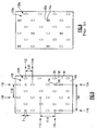
- the impingement channels 74 are arranged within an array 106 having a plurality of rows 110 and 112, and a plurality of columns 114 and 116.
- the impingement channels 74 each have a diameter D, which provides a reference for establishing spacing within the array 106.
- the distance between the centers of the impingement channels 74 in the row 110 and the centers of the impingement channels 74 in the adjacent row 112 is about 7.1 times the diameter D.
- the distance between the centers of the impingement channels 74 within the column 114 and the centers of the impingement channels 74 in the adjacent column 116 is about 14 times the diameter D.
- the film channels 82 are arranged in an array 128.
- the density of the array 128 is greater than the density of the array 106. That is, there are more film channels 82 than impingement channels 74 within a similarly sized area.
- the array 128 of film channels 82 has a plurality of rows 132 and 134, and a plurality of columns 136 and 138.
- the distance between the centers of the film channels 82 in the row 132 and the centers of the film channels 82 in the adjacent row 134 is about 3.5 times the diameter D.
- the distance between the centers of the film channels 82 within the column 136 and the centers of the film channels 82 in the column 138 is about 7.1 times the diameter D.
- the array 106 of impingement channels 74 is staggered relative to the array 128 of fluid channels 82. That is, the impingement channels 74 are positioned between adjacent ones of the film channels 82 in the direction 5.
- the distance between the impingement plate 78 and the film plate 86 is about 3 times the diameter D. In other examples, the distance between the impingement plate 78 and the film plate 86 ranges from 2 times the diameter D to 4 times the diameter D.
- an array 106a of impingement channels 74a is not staggered relative to an array 128a of a film channels 82a. That is, in the prior art, the impingement channels 74a are positioned in line with the film channels 82a. Accordingly, in the prior art, the fluid and the particulate matter that is communicated through the impingement channels 74a is directed at the film channel 82a, not between the impingement channels 74a.
- Features of this invention include an array of impingement channels staggered relative to an array of film channels such that particulate matter carried by fluid through the impingement channels directly impinges between the film channels on the film plate.
Landscapes
- Engineering & Computer Science (AREA)
- Mechanical Engineering (AREA)
- General Engineering & Computer Science (AREA)
- Turbine Rotor Nozzle Sealing (AREA)
Claims (11)
- Kühlanordnung für eine Turbinenkomponente (58), umfassend:eine Turbinenkomponente (58) mit einem Filmkühlungsabschnitt und einem Anblaskühlungsabschnitt, der in einem Abstand von dem Filmkühlungsabschnitt beabstandet ist,wobei der Filmkühlungsabschnitt ein Filmkanalarray (128) mit einer Vielzahl von Filmkanälen (82) herstellt, die sich jeweils an einer Filmkanalachse von einem Filmkanaleingang (98) auf einer ersten Seite des Filmkühlungsabschnitts zu einem Filmkanalausgang (102) auf einer gegenüberliegenden zweiten Seite des Filmkühlungsabschnitts erstrecken,wobei der Anblaskühlungsabschnitt ein Anblaskühlungsarray (106) mit einer Vielzahl von Anblaskanälen (74) herstellt, die sich jeweils an einer Anblasachse von einem Anblaskanaleingang (90) auf einer ersten Seite des Anblaskühlungsabschnitts zu einem Anblaskanalausgang (94) auf einer gegenüberliegenden zweiten Seite des Anblaskühlungsabschnitts erstrecken, wobei das Filmkanalarray (106) relativ zu dem Anblaskühlungsarray (128) versetzt ist,wobei die Anblaskanäle (74) dazu konfiguriert sind, Fluid und Partikelmaterial, das von dem Fluid befördert wird, unmittelbar zwischen den Filmkanaleingängen (98) des Filmkühlungsabschnitts zu leiten; und dadurch gekennzeichnet, dassder Abstand zwischen zwei und vier Mal größer als ein Durchmesser einzelner der Vielzahl von Anblaskanälen (74) ist.
- Kühlanordnung nach Anspruch 1, wobei der Abstand drei Mal größer als ein Durchmesser einzelner der Vielzahl von Anblaskanälen (74) ist.
- Kühlanordnung nach einem der vorangehenden Ansprüche, wobei die Anblaskanäle (74) einen kreisförmigen Querschnitt aufweisen und die Filmkanäle (82) einen ovalen Querschnitt aufweisen.
- Kühlanordnung nach einem der vorangehenden Ansprüche, wobei die Anblaskanäle (74) sich an einer Achse erstrecken, die senkrecht zu einer umgebenden Fläche der Anblasplatte (78) oder des Anblaskühlungsabschnitts ist.
- Turbinenkomponentenkühlungsanordnung nach Anspruch 4, wobei die Filmkanäle (82) quer zu der Vielzahl von Anblaskanälen (74) sind.
- Turbinenkomponentenkühlungsanordnung nach einem der vorangehenden Ansprüche, wobei die Vielzahl von Filmkanälen (82) und/oder Anblaskanälen (74) gleichmäßig über die Filmplatte (86) verteilt sind.
- Kühlanordnung nach einem der vorangehenden Ansprüche, wobei die Anblaskanalachsen sich zwischen den Filmkanaleingängen (98) erstrecken.
- Kühlanordnung nach einem der vorangehenden Ansprüche, wobei die Anblaskanalachsen nicht mit den Filmkanaleingängen (98) übereinstimmen.
- Kühlanordnung nach einem der vorangehenden Ansprüche, wobei die Anblaskanalachsen im Verhältnis zu den Filmkanalachsen in einem Winkel angeordnet sind, der nicht null ist.
- Kühlanordnung nach einem der vorangehenden Ansprüche, wobei die Anblaskanalachsen die Filmplatte oder den Kühlungsabschnitt (86) zwischen den Filmkanaleingängen (98) schneiden.
- Kühlanordnung nach einem der vorangehenden Ansprüche, wobei die Turbinenkomponente eine äußere Schaufelluftdichtung (58) ist.
Applications Claiming Priority (1)
| Application Number | Priority Date | Filing Date | Title |
|---|---|---|---|
| US12/402,590 US9145779B2 (en) | 2009-03-12 | 2009-03-12 | Cooling arrangement for a turbine engine component |
Publications (3)
| Publication Number | Publication Date |
|---|---|
| EP2236765A2 EP2236765A2 (de) | 2010-10-06 |
| EP2236765A3 EP2236765A3 (de) | 2015-04-29 |
| EP2236765B1 true EP2236765B1 (de) | 2016-08-03 |
Family
ID=42352302
Family Applications (1)
| Application Number | Title | Priority Date | Filing Date |
|---|---|---|---|
| EP10250221.8A Active EP2236765B1 (de) | 2009-03-12 | 2010-02-10 | Kühlanordnung für Turbinenmotorkomponenten |
Country Status (2)
| Country | Link |
|---|---|
| US (1) | US9145779B2 (de) |
| EP (1) | EP2236765B1 (de) |
Families Citing this family (19)
| Publication number | Priority date | Publication date | Assignee | Title |
|---|---|---|---|---|
| US9458855B2 (en) * | 2010-12-30 | 2016-10-04 | Rolls-Royce North American Technologies Inc. | Compressor tip clearance control and gas turbine engine |
| US8475121B1 (en) * | 2011-01-17 | 2013-07-02 | Florida Turbine Technologies, Inc. | Ring segment for industrial gas turbine |
| US8475122B1 (en) * | 2011-01-17 | 2013-07-02 | Florida Turbine Technologies, Inc. | Blade outer air seal with circumferential cooled teeth |
| US8998572B2 (en) * | 2012-06-04 | 2015-04-07 | United Technologies Corporation | Blade outer air seal for a gas turbine engine |
| US20140064969A1 (en) * | 2012-08-29 | 2014-03-06 | Dmitriy A. Romanov | Blade outer air seal |
| GB201300597D0 (en) * | 2012-10-22 | 2013-02-27 | Rolls Royce Plc | Clearance control |
| DE102012025375A1 (de) * | 2012-12-27 | 2014-07-17 | Rolls-Royce Deutschland Ltd & Co Kg | Verfahren zur Anordnung von Prallkühllöchern und Effusionslöchern in einer Brennkammerwand einer Gasturbine |
| EP2754858B1 (de) * | 2013-01-14 | 2015-09-16 | Alstom Technology Ltd | Anordnung zum Abdichten eines offenen Hohlraums gegen Heißgaseinschluss |
| EP2949871B1 (de) * | 2014-05-07 | 2017-03-01 | United Technologies Corporation | Variables leitschaufelsegment |
| EP3149284A2 (de) * | 2014-05-29 | 2017-04-05 | General Electric Company | Motorkomponenten mit prallkühlungsfunktionen |
| US10018068B2 (en) * | 2015-01-13 | 2018-07-10 | United Technologies Corporation | Blade outer air seal with cooling holes |
| US10605093B2 (en) * | 2016-07-12 | 2020-03-31 | General Electric Company | Heat transfer device and related turbine airfoil |
| US10626751B2 (en) | 2017-05-30 | 2020-04-21 | United Technologies Corporation | Turbine cooling air metering arrangement |
| US10619504B2 (en) * | 2017-10-31 | 2020-04-14 | United Technologies Corporation | Gas turbine engine blade outer air seal cooling hole configuration |
| US10502093B2 (en) * | 2017-12-13 | 2019-12-10 | Pratt & Whitney Canada Corp. | Turbine shroud cooling |
| US10689997B2 (en) * | 2018-04-17 | 2020-06-23 | Raytheon Technologies Corporation | Seal assembly for gas turbine engine |
| US10704408B2 (en) * | 2018-05-03 | 2020-07-07 | Rolls-Royce North American Technologies Inc. | Dual response blade track system |
| US12467629B1 (en) * | 2025-01-15 | 2025-11-11 | Rtx Corporation | CMC component with cover plate |
| CN120331888B (zh) * | 2025-06-20 | 2025-10-03 | 中国航发湖南动力机械研究所 | 涡轮叶片尾缘冷却结构、设计方法及航空发动机 |
Family Cites Families (20)
| Publication number | Priority date | Publication date | Assignee | Title |
|---|---|---|---|---|
| US4526226A (en) * | 1981-08-31 | 1985-07-02 | General Electric Company | Multiple-impingement cooled structure |
| JPH0660740B2 (ja) * | 1985-04-05 | 1994-08-10 | 工業技術院長 | ガスタービンの燃焼器 |
| US5246347A (en) * | 1988-05-17 | 1993-09-21 | Patients Solutions, Inc. | Infusion device with disposable elements |
| US5405242A (en) * | 1990-07-09 | 1995-04-11 | United Technologies Corporation | Cooled vane |
| IL96886A (en) * | 1991-01-06 | 1994-08-26 | Israel Aircraft Ind Ltd | Apparatus for separating relatively more dense particulate matter from a relatively less dense fluid flow |
| US5165847A (en) * | 1991-05-20 | 1992-11-24 | General Electric Company | Tapered enlargement metering inlet channel for a shroud cooling assembly of gas turbine engines |
| US5271715A (en) * | 1992-12-21 | 1993-12-21 | United Technologies Corporation | Cooled turbine blade |
| US5688104A (en) * | 1993-11-24 | 1997-11-18 | United Technologies Corporation | Airfoil having expanded wall portions to accommodate film cooling holes |
| FR2723177B1 (fr) * | 1994-07-27 | 1996-09-06 | Snecma | Chambre de combustion comportant une double paroi |
| GB2343486B (en) * | 1998-06-19 | 2000-09-20 | Rolls Royce Plc | Improvemnts in or relating to cooling systems for gas turbine engine airfoil |
| US6237344B1 (en) * | 1998-07-20 | 2001-05-29 | General Electric Company | Dimpled impingement baffle |
| GB0117110D0 (en) * | 2001-07-13 | 2001-09-05 | Siemens Ag | Coolable segment for a turbomachinery and combustion turbine |
| US6964170B2 (en) | 2003-04-28 | 2005-11-15 | Pratt & Whitney Canada Corp. | Noise reducing combustor |
| US7186084B2 (en) * | 2003-11-19 | 2007-03-06 | General Electric Company | Hot gas path component with mesh and dimpled cooling |
| JP4191578B2 (ja) * | 2003-11-21 | 2008-12-03 | 三菱重工業株式会社 | ガスタービンエンジンのタービン冷却翼 |
| US7270175B2 (en) * | 2004-01-09 | 2007-09-18 | United Technologies Corporation | Extended impingement cooling device and method |
| US7219498B2 (en) * | 2004-09-10 | 2007-05-22 | Honeywell International, Inc. | Waffled impingement effusion method |
| US7413406B2 (en) * | 2006-02-15 | 2008-08-19 | United Technologies Corporation | Turbine blade with radial cooling channels |
| JP4845957B2 (ja) * | 2006-03-02 | 2011-12-28 | 株式会社Ihi | インピンジメント冷却構造 |
| US7704039B1 (en) * | 2007-03-21 | 2010-04-27 | Florida Turbine Technologies, Inc. | BOAS with multiple trenched film cooling slots |
-
2009
- 2009-03-12 US US12/402,590 patent/US9145779B2/en active Active
-
2010
- 2010-02-10 EP EP10250221.8A patent/EP2236765B1/de active Active
Also Published As
| Publication number | Publication date |
|---|---|
| EP2236765A3 (de) | 2015-04-29 |
| EP2236765A2 (de) | 2010-10-06 |
| US9145779B2 (en) | 2015-09-29 |
| US20100232929A1 (en) | 2010-09-16 |
Similar Documents
| Publication | Publication Date | Title |
|---|---|---|
| EP2236765B1 (de) | Kühlanordnung für Turbinenmotorkomponenten | |
| US7029228B2 (en) | Method and apparatus for convective cooling of side-walls of turbine nozzle segments | |
| EP2055898B1 (de) | Gasturbinentriebwerk mit in Umfangsrichtung angeordneten Schaufeln mit Plattformkühlung | |
| EP1956192B1 (de) | Kühlsystem für Gasturbinenbauteil | |
| EP3088675B1 (de) | Laufschaufel und zugehörige gasturbine | |
| EP2236749B1 (de) | Turbinenlaufschaufel und zugehöriges Kühlverfahren | |
| EP3191689B1 (de) | Gekühlte turbinenleitschaufelplattform mit vorderen, mittelsehnen- und hinteren kühlkammern in der plattform | |
| US10386069B2 (en) | Gas turbine engine wall | |
| EP3176372B1 (de) | Gekühltes bauteil einer turbomaschine | |
| US11773729B2 (en) | Component for a gas turbine engine with a film hole | |
| EP2927430B1 (de) | Statorschaufel mit einer gekühlten plattform für ein gasturbinentriebwerk | |
| EP3088674B1 (de) | Rotorblatt und zugehörige gasturbine | |
| US8573925B2 (en) | Cooled component for a gas turbine engine | |
| EP2597264A2 (de) | Kühlanordnung einer Schaufel | |
| EP2436881B1 (de) | Leitschaufelendwand für einen Gasturbinenmotor | |
| EP3514331B1 (de) | Gekühltes schaufelblatt und zugehöriges gasturbinentriebwerk | |
| EP2947280B1 (de) | Turbinendüsen und kühlsysteme zum kühlen von gleitgelenken darin | |
| KR101974735B1 (ko) | 가스 터빈 | |
| EP3628818B1 (de) | Prallkühlung für eine gasturbinenmotorkomponente | |
| US20080286116A1 (en) | Cooling arrangement | |
| EP3567218B1 (de) | Schaufelblatt mit verbessertem vorderkantenkühlschema und beschädigungswiderstand | |
| EP3567219B1 (de) | Schaufelblatt eines gasturbinentriebwerks | |
| US20150354369A1 (en) | Gas turbine engine airfoil platform cooling | |
| EP3184736B1 (de) | Angewinkeltes wärmetransfergestell | |
| US20250163813A1 (en) | Airfoil assembly with platform cooling |
Legal Events
| Date | Code | Title | Description |
|---|---|---|---|
| PUAI | Public reference made under article 153(3) epc to a published international application that has entered the european phase |
Free format text: ORIGINAL CODE: 0009012 |
|
| AK | Designated contracting states |
Kind code of ref document: A2 Designated state(s): AT BE BG CH CY CZ DE DK EE ES FI FR GB GR HR HU IE IS IT LI LT LU LV MC MK MT NL NO PL PT RO SE SI SK SM TR |
|
| AX | Request for extension of the european patent |
Extension state: AL BA RS |
|
| RIC1 | Information provided on ipc code assigned before grant |
Ipc: F01D 9/04 20060101AFI20150108BHEP Ipc: F01D 11/10 20060101ALI20150108BHEP Ipc: F01D 25/24 20060101ALI20150108BHEP |
|
| PUAL | Search report despatched |
Free format text: ORIGINAL CODE: 0009013 |
|
| AK | Designated contracting states |
Kind code of ref document: A3 Designated state(s): AT BE BG CH CY CZ DE DK EE ES FI FR GB GR HR HU IE IS IT LI LT LU LV MC MK MT NL NO PL PT RO SE SI SK SM TR |
|
| AX | Request for extension of the european patent |
Extension state: AL BA RS |
|
| RIC1 | Information provided on ipc code assigned before grant |
Ipc: F01D 25/24 20060101ALI20150325BHEP Ipc: F01D 11/10 20060101ALI20150325BHEP Ipc: F01D 9/04 20060101AFI20150325BHEP |
|
| 17P | Request for examination filed |
Effective date: 20151028 |
|
| RBV | Designated contracting states (corrected) |
Designated state(s): AT BE BG CH CY CZ DE DK EE ES FI FR GB GR HR HU IE IS IT LI LT LU LV MC MK MT NL NO PL PT RO SE SI SK SM TR |
|
| GRAP | Despatch of communication of intention to grant a patent |
Free format text: ORIGINAL CODE: EPIDOSNIGR1 |
|
| INTG | Intention to grant announced |
Effective date: 20160212 |
|
| GRAS | Grant fee paid |
Free format text: ORIGINAL CODE: EPIDOSNIGR3 |
|
| GRAA | (expected) grant |
Free format text: ORIGINAL CODE: 0009210 |
|
| AK | Designated contracting states |
Kind code of ref document: B1 Designated state(s): AT BE BG CH CY CZ DE DK EE ES FI FR GB GR HR HU IE IS IT LI LT LU LV MC MK MT NL NO PL PT RO SE SI SK SM TR |
|
| REG | Reference to a national code |
Ref country code: GB Ref legal event code: FG4D |
|
| REG | Reference to a national code |
Ref country code: CH Ref legal event code: EP Ref country code: AT Ref legal event code: REF Ref document number: 817475 Country of ref document: AT Kind code of ref document: T Effective date: 20160815 |
|
| REG | Reference to a national code |
Ref country code: IE Ref legal event code: FG4D |
|
| REG | Reference to a national code |
Ref country code: DE Ref legal event code: R096 Ref document number: 602010035161 Country of ref document: DE |
|
| REG | Reference to a national code |
Ref country code: CH Ref legal event code: PCOW Free format text: NEW ADDRESS: 10 FARM SPRINGS RD., FARMINGTON, CT 06032 (US) |
|
| RAP2 | Party data changed (patent owner data changed or rights of a patent transferred) |
Owner name: UNITED TECHNOLOGIES CORPORATION |
|
| REG | Reference to a national code |
Ref country code: NL Ref legal event code: MP Effective date: 20160803 |
|
| REG | Reference to a national code |
Ref country code: LT Ref legal event code: MG4D |
|
| REG | Reference to a national code |
Ref country code: AT Ref legal event code: MK05 Ref document number: 817475 Country of ref document: AT Kind code of ref document: T Effective date: 20160803 |
|
| PG25 | Lapsed in a contracting state [announced via postgrant information from national office to epo] |
Ref country code: IS Free format text: LAPSE BECAUSE OF FAILURE TO SUBMIT A TRANSLATION OF THE DESCRIPTION OR TO PAY THE FEE WITHIN THE PRESCRIBED TIME-LIMIT Effective date: 20161203 Ref country code: FI Free format text: LAPSE BECAUSE OF FAILURE TO SUBMIT A TRANSLATION OF THE DESCRIPTION OR TO PAY THE FEE WITHIN THE PRESCRIBED TIME-LIMIT Effective date: 20160803 Ref country code: NO Free format text: LAPSE BECAUSE OF FAILURE TO SUBMIT A TRANSLATION OF THE DESCRIPTION OR TO PAY THE FEE WITHIN THE PRESCRIBED TIME-LIMIT Effective date: 20161103 Ref country code: HR Free format text: LAPSE BECAUSE OF FAILURE TO SUBMIT A TRANSLATION OF THE DESCRIPTION OR TO PAY THE FEE WITHIN THE PRESCRIBED TIME-LIMIT Effective date: 20160803 Ref country code: LT Free format text: LAPSE BECAUSE OF FAILURE TO SUBMIT A TRANSLATION OF THE DESCRIPTION OR TO PAY THE FEE WITHIN THE PRESCRIBED TIME-LIMIT Effective date: 20160803 Ref country code: IT Free format text: LAPSE BECAUSE OF FAILURE TO SUBMIT A TRANSLATION OF THE DESCRIPTION OR TO PAY THE FEE WITHIN THE PRESCRIBED TIME-LIMIT Effective date: 20160803 Ref country code: NL Free format text: LAPSE BECAUSE OF FAILURE TO SUBMIT A TRANSLATION OF THE DESCRIPTION OR TO PAY THE FEE WITHIN THE PRESCRIBED TIME-LIMIT Effective date: 20160803 |
|
| PG25 | Lapsed in a contracting state [announced via postgrant information from national office to epo] |
Ref country code: SE Free format text: LAPSE BECAUSE OF FAILURE TO SUBMIT A TRANSLATION OF THE DESCRIPTION OR TO PAY THE FEE WITHIN THE PRESCRIBED TIME-LIMIT Effective date: 20160803 Ref country code: PT Free format text: LAPSE BECAUSE OF FAILURE TO SUBMIT A TRANSLATION OF THE DESCRIPTION OR TO PAY THE FEE WITHIN THE PRESCRIBED TIME-LIMIT Effective date: 20161205 Ref country code: GR Free format text: LAPSE BECAUSE OF FAILURE TO SUBMIT A TRANSLATION OF THE DESCRIPTION OR TO PAY THE FEE WITHIN THE PRESCRIBED TIME-LIMIT Effective date: 20161104 Ref country code: AT Free format text: LAPSE BECAUSE OF FAILURE TO SUBMIT A TRANSLATION OF THE DESCRIPTION OR TO PAY THE FEE WITHIN THE PRESCRIBED TIME-LIMIT Effective date: 20160803 Ref country code: PL Free format text: LAPSE BECAUSE OF FAILURE TO SUBMIT A TRANSLATION OF THE DESCRIPTION OR TO PAY THE FEE WITHIN THE PRESCRIBED TIME-LIMIT Effective date: 20160803 Ref country code: LV Free format text: LAPSE BECAUSE OF FAILURE TO SUBMIT A TRANSLATION OF THE DESCRIPTION OR TO PAY THE FEE WITHIN THE PRESCRIBED TIME-LIMIT Effective date: 20160803 Ref country code: ES Free format text: LAPSE BECAUSE OF FAILURE TO SUBMIT A TRANSLATION OF THE DESCRIPTION OR TO PAY THE FEE WITHIN THE PRESCRIBED TIME-LIMIT Effective date: 20160803 |
|
| PG25 | Lapsed in a contracting state [announced via postgrant information from national office to epo] |
Ref country code: EE Free format text: LAPSE BECAUSE OF FAILURE TO SUBMIT A TRANSLATION OF THE DESCRIPTION OR TO PAY THE FEE WITHIN THE PRESCRIBED TIME-LIMIT Effective date: 20160803 Ref country code: RO Free format text: LAPSE BECAUSE OF FAILURE TO SUBMIT A TRANSLATION OF THE DESCRIPTION OR TO PAY THE FEE WITHIN THE PRESCRIBED TIME-LIMIT Effective date: 20160803 |
|
| REG | Reference to a national code |
Ref country code: DE Ref legal event code: R097 Ref document number: 602010035161 Country of ref document: DE |
|
| PG25 | Lapsed in a contracting state [announced via postgrant information from national office to epo] |
Ref country code: DK Free format text: LAPSE BECAUSE OF FAILURE TO SUBMIT A TRANSLATION OF THE DESCRIPTION OR TO PAY THE FEE WITHIN THE PRESCRIBED TIME-LIMIT Effective date: 20160803 Ref country code: SM Free format text: LAPSE BECAUSE OF FAILURE TO SUBMIT A TRANSLATION OF THE DESCRIPTION OR TO PAY THE FEE WITHIN THE PRESCRIBED TIME-LIMIT Effective date: 20160803 Ref country code: CZ Free format text: LAPSE BECAUSE OF FAILURE TO SUBMIT A TRANSLATION OF THE DESCRIPTION OR TO PAY THE FEE WITHIN THE PRESCRIBED TIME-LIMIT Effective date: 20160803 Ref country code: SK Free format text: LAPSE BECAUSE OF FAILURE TO SUBMIT A TRANSLATION OF THE DESCRIPTION OR TO PAY THE FEE WITHIN THE PRESCRIBED TIME-LIMIT Effective date: 20160803 Ref country code: BE Free format text: LAPSE BECAUSE OF FAILURE TO SUBMIT A TRANSLATION OF THE DESCRIPTION OR TO PAY THE FEE WITHIN THE PRESCRIBED TIME-LIMIT Effective date: 20160803 Ref country code: BG Free format text: LAPSE BECAUSE OF FAILURE TO SUBMIT A TRANSLATION OF THE DESCRIPTION OR TO PAY THE FEE WITHIN THE PRESCRIBED TIME-LIMIT Effective date: 20161103 |
|
| PLBE | No opposition filed within time limit |
Free format text: ORIGINAL CODE: 0009261 |
|
| STAA | Information on the status of an ep patent application or granted ep patent |
Free format text: STATUS: NO OPPOSITION FILED WITHIN TIME LIMIT |
|
| 26N | No opposition filed |
Effective date: 20170504 |
|
| REG | Reference to a national code |
Ref country code: DE Ref legal event code: R082 Ref document number: 602010035161 Country of ref document: DE Representative=s name: SCHMITT-NILSON SCHRAUD WAIBEL WOHLFROM PATENTA, DE |
|
| PG25 | Lapsed in a contracting state [announced via postgrant information from national office to epo] |
Ref country code: SI Free format text: LAPSE BECAUSE OF FAILURE TO SUBMIT A TRANSLATION OF THE DESCRIPTION OR TO PAY THE FEE WITHIN THE PRESCRIBED TIME-LIMIT Effective date: 20160803 |
|
| PG25 | Lapsed in a contracting state [announced via postgrant information from national office to epo] |
Ref country code: MC Free format text: LAPSE BECAUSE OF FAILURE TO SUBMIT A TRANSLATION OF THE DESCRIPTION OR TO PAY THE FEE WITHIN THE PRESCRIBED TIME-LIMIT Effective date: 20160803 |
|
| REG | Reference to a national code |
Ref country code: CH Ref legal event code: PL |
|
| PG25 | Lapsed in a contracting state [announced via postgrant information from national office to epo] |
Ref country code: CH Free format text: LAPSE BECAUSE OF NON-PAYMENT OF DUE FEES Effective date: 20170228 Ref country code: LI Free format text: LAPSE BECAUSE OF NON-PAYMENT OF DUE FEES Effective date: 20170228 |
|
| REG | Reference to a national code |
Ref country code: IE Ref legal event code: MM4A |
|
| REG | Reference to a national code |
Ref country code: FR Ref legal event code: ST Effective date: 20171031 |
|
| PG25 | Lapsed in a contracting state [announced via postgrant information from national office to epo] |
Ref country code: LU Free format text: LAPSE BECAUSE OF NON-PAYMENT OF DUE FEES Effective date: 20170210 |
|
| PG25 | Lapsed in a contracting state [announced via postgrant information from national office to epo] |
Ref country code: FR Free format text: LAPSE BECAUSE OF NON-PAYMENT OF DUE FEES Effective date: 20170228 |
|
| PG25 | Lapsed in a contracting state [announced via postgrant information from national office to epo] |
Ref country code: IE Free format text: LAPSE BECAUSE OF NON-PAYMENT OF DUE FEES Effective date: 20170210 |
|
| PG25 | Lapsed in a contracting state [announced via postgrant information from national office to epo] |
Ref country code: MT Free format text: LAPSE BECAUSE OF NON-PAYMENT OF DUE FEES Effective date: 20170210 |
|
| PG25 | Lapsed in a contracting state [announced via postgrant information from national office to epo] |
Ref country code: HU Free format text: LAPSE BECAUSE OF FAILURE TO SUBMIT A TRANSLATION OF THE DESCRIPTION OR TO PAY THE FEE WITHIN THE PRESCRIBED TIME-LIMIT; INVALID AB INITIO Effective date: 20100210 |
|
| PG25 | Lapsed in a contracting state [announced via postgrant information from national office to epo] |
Ref country code: CY Free format text: LAPSE BECAUSE OF NON-PAYMENT OF DUE FEES Effective date: 20160803 |
|
| PG25 | Lapsed in a contracting state [announced via postgrant information from national office to epo] |
Ref country code: MK Free format text: LAPSE BECAUSE OF FAILURE TO SUBMIT A TRANSLATION OF THE DESCRIPTION OR TO PAY THE FEE WITHIN THE PRESCRIBED TIME-LIMIT Effective date: 20160803 |
|
| PG25 | Lapsed in a contracting state [announced via postgrant information from national office to epo] |
Ref country code: TR Free format text: LAPSE BECAUSE OF FAILURE TO SUBMIT A TRANSLATION OF THE DESCRIPTION OR TO PAY THE FEE WITHIN THE PRESCRIBED TIME-LIMIT Effective date: 20160803 |
|
| REG | Reference to a national code |
Ref country code: DE Ref legal event code: R081 Ref document number: 602010035161 Country of ref document: DE Owner name: RAYTHEON TECHNOLOGIES CORPORATION (N.D.GES.D.S, US Free format text: FORMER OWNER: UNITED TECHNOLOGIES CORPORATION, HARTFORD, CONN., US Ref country code: DE Ref legal event code: R081 Ref document number: 602010035161 Country of ref document: DE Owner name: RTX CORPORATION (N.D.GES.D. STAATES DELAWARE),, US Free format text: FORMER OWNER: UNITED TECHNOLOGIES CORPORATION, HARTFORD, CONN., US |
|
| P01 | Opt-out of the competence of the unified patent court (upc) registered |
Effective date: 20230519 |
|
| PGFP | Annual fee paid to national office [announced via postgrant information from national office to epo] |
Ref country code: DE Payment date: 20250122 Year of fee payment: 16 |
|
| PGFP | Annual fee paid to national office [announced via postgrant information from national office to epo] |
Ref country code: GB Payment date: 20250123 Year of fee payment: 16 |
|
| REG | Reference to a national code |
Ref country code: DE Ref legal event code: R081 Ref document number: 602010035161 Country of ref document: DE Owner name: RTX CORPORATION (N.D.GES.D. STAATES DELAWARE),, US Free format text: FORMER OWNER: RAYTHEON TECHNOLOGIES CORPORATION (N.D.GES.D.STAATES DELAWARE), ARLINGTON, VA, US |