EP2236643A2 - Vorrichtung zur Elektronenstrahl-Dampfabscheidung und Beschichtungsverfahren - Google Patents
Vorrichtung zur Elektronenstrahl-Dampfabscheidung und Beschichtungsverfahren Download PDFInfo
- Publication number
- EP2236643A2 EP2236643A2 EP10250662A EP10250662A EP2236643A2 EP 2236643 A2 EP2236643 A2 EP 2236643A2 EP 10250662 A EP10250662 A EP 10250662A EP 10250662 A EP10250662 A EP 10250662A EP 2236643 A2 EP2236643 A2 EP 2236643A2
- Authority
- EP
- European Patent Office
- Prior art keywords
- coating
- mode
- source
- work piece
- vapor deposition
- Prior art date
- Legal status (The legal status is an assumption and is not a legal conclusion. Google has not performed a legal analysis and makes no representation as to the accuracy of the status listed.)
- Withdrawn
Links
- 238000000576 coating method Methods 0.000 title claims abstract description 140
- 239000011248 coating agent Substances 0.000 title claims abstract description 135
- 238000010894 electron beam technology Methods 0.000 title claims abstract description 36
- 238000007740 vapor deposition Methods 0.000 title claims abstract description 31
- 238000000034 method Methods 0.000 title claims description 16
- 238000000151 deposition Methods 0.000 claims abstract description 102
- 230000008021 deposition Effects 0.000 claims abstract description 75
- 239000000463 material Substances 0.000 claims abstract description 35
- 230000004044 response Effects 0.000 claims abstract description 14
- 239000007789 gas Substances 0.000 claims description 42
- 238000005240 physical vapour deposition Methods 0.000 claims description 27
- 230000008569 process Effects 0.000 claims description 6
- 239000012159 carrier gas Substances 0.000 claims description 4
- 238000001704 evaporation Methods 0.000 claims description 4
- 238000005137 deposition process Methods 0.000 claims description 3
- 238000005019 vapor deposition process Methods 0.000 claims description 2
- 238000005524 ceramic coating Methods 0.000 description 5
- 239000002245 particle Substances 0.000 description 3
- MCMNRKCIXSYSNV-UHFFFAOYSA-N Zirconium dioxide Chemical compound O=[Zr]=O MCMNRKCIXSYSNV-UHFFFAOYSA-N 0.000 description 2
- 230000008901 benefit Effects 0.000 description 2
- 230000008859 change Effects 0.000 description 2
- CMIHHWBVHJVIGI-UHFFFAOYSA-N gadolinium(iii) oxide Chemical compound [O-2].[O-2].[O-2].[Gd+3].[Gd+3] CMIHHWBVHJVIGI-UHFFFAOYSA-N 0.000 description 2
- QVGXLLKOCUKJST-UHFFFAOYSA-N atomic oxygen Chemical compound [O] QVGXLLKOCUKJST-UHFFFAOYSA-N 0.000 description 1
- 239000000919 ceramic Substances 0.000 description 1
- 238000004891 communication Methods 0.000 description 1
- 239000002826 coolant Substances 0.000 description 1
- 238000005260 corrosion Methods 0.000 description 1
- 230000007797 corrosion Effects 0.000 description 1
- 238000003780 insertion Methods 0.000 description 1
- 230000037431 insertion Effects 0.000 description 1
- 230000008018 melting Effects 0.000 description 1
- 238000002844 melting Methods 0.000 description 1
- 229910001092 metal group alloy Inorganic materials 0.000 description 1
- 238000012986 modification Methods 0.000 description 1
- 230000004048 modification Effects 0.000 description 1
- 239000001301 oxygen Substances 0.000 description 1
- 229910052760 oxygen Inorganic materials 0.000 description 1
- 230000003068 static effect Effects 0.000 description 1
- 239000012720 thermal barrier coating Substances 0.000 description 1
- XLYOFNOQVPJJNP-UHFFFAOYSA-N water Substances O XLYOFNOQVPJJNP-UHFFFAOYSA-N 0.000 description 1
- RUDFQVOCFDJEEF-UHFFFAOYSA-N yttrium(III) oxide Inorganic materials [O-2].[O-2].[O-2].[Y+3].[Y+3] RUDFQVOCFDJEEF-UHFFFAOYSA-N 0.000 description 1
Images
Classifications
-
- C—CHEMISTRY; METALLURGY
- C23—COATING METALLIC MATERIAL; COATING MATERIAL WITH METALLIC MATERIAL; CHEMICAL SURFACE TREATMENT; DIFFUSION TREATMENT OF METALLIC MATERIAL; COATING BY VACUUM EVAPORATION, BY SPUTTERING, BY ION IMPLANTATION OR BY CHEMICAL VAPOUR DEPOSITION, IN GENERAL; INHIBITING CORROSION OF METALLIC MATERIAL OR INCRUSTATION IN GENERAL
- C23C—COATING METALLIC MATERIAL; COATING MATERIAL WITH METALLIC MATERIAL; SURFACE TREATMENT OF METALLIC MATERIAL BY DIFFUSION INTO THE SURFACE, BY CHEMICAL CONVERSION OR SUBSTITUTION; COATING BY VACUUM EVAPORATION, BY SPUTTERING, BY ION IMPLANTATION OR BY CHEMICAL VAPOUR DEPOSITION, IN GENERAL
- C23C14/00—Coating by vacuum evaporation, by sputtering or by ion implantation of the coating forming material
- C23C14/22—Coating by vacuum evaporation, by sputtering or by ion implantation of the coating forming material characterised by the process of coating
- C23C14/24—Vacuum evaporation
- C23C14/28—Vacuum evaporation by wave energy or particle radiation
- C23C14/30—Vacuum evaporation by wave energy or particle radiation by electron bombardment
-
- C—CHEMISTRY; METALLURGY
- C23—COATING METALLIC MATERIAL; COATING MATERIAL WITH METALLIC MATERIAL; CHEMICAL SURFACE TREATMENT; DIFFUSION TREATMENT OF METALLIC MATERIAL; COATING BY VACUUM EVAPORATION, BY SPUTTERING, BY ION IMPLANTATION OR BY CHEMICAL VAPOUR DEPOSITION, IN GENERAL; INHIBITING CORROSION OF METALLIC MATERIAL OR INCRUSTATION IN GENERAL
- C23C—COATING METALLIC MATERIAL; COATING MATERIAL WITH METALLIC MATERIAL; SURFACE TREATMENT OF METALLIC MATERIAL BY DIFFUSION INTO THE SURFACE, BY CHEMICAL CONVERSION OR SUBSTITUTION; COATING BY VACUUM EVAPORATION, BY SPUTTERING, BY ION IMPLANTATION OR BY CHEMICAL VAPOUR DEPOSITION, IN GENERAL
- C23C14/00—Coating by vacuum evaporation, by sputtering or by ion implantation of the coating forming material
- C23C14/04—Coating on selected surface areas, e.g. using masks
- C23C14/046—Coating cavities or hollow spaces, e.g. interior of tubes; Infiltration of porous substrates
-
- H—ELECTRICITY
- H01—ELECTRIC ELEMENTS
- H01J—ELECTRIC DISCHARGE TUBES OR DISCHARGE LAMPS
- H01J37/00—Discharge tubes with provision for introducing objects or material to be exposed to the discharge, e.g. for the purpose of examination or processing thereof
- H01J37/30—Electron-beam or ion-beam tubes for localised treatment of objects
- H01J37/305—Electron-beam or ion-beam tubes for localised treatment of objects for casting, melting, evaporating, or etching
- H01J37/3053—Electron-beam or ion-beam tubes for localised treatment of objects for casting, melting, evaporating, or etching for evaporating or etching
-
- H—ELECTRICITY
- H01—ELECTRIC ELEMENTS
- H01J—ELECTRIC DISCHARGE TUBES OR DISCHARGE LAMPS
- H01J37/00—Discharge tubes with provision for introducing objects or material to be exposed to the discharge, e.g. for the purpose of examination or processing thereof
- H01J37/30—Electron-beam or ion-beam tubes for localised treatment of objects
- H01J37/317—Electron-beam or ion-beam tubes for localised treatment of objects for changing properties of the objects or for applying thin layers thereon, e.g. for ion implantation
- H01J37/3178—Electron-beam or ion-beam tubes for localised treatment of objects for changing properties of the objects or for applying thin layers thereon, e.g. for ion implantation for applying thin layers on objects
-
- H—ELECTRICITY
- H01—ELECTRIC ELEMENTS
- H01J—ELECTRIC DISCHARGE TUBES OR DISCHARGE LAMPS
- H01J2237/00—Discharge tubes exposing object to beam, e.g. for analysis treatment, etching, imaging
- H01J2237/30—Electron or ion beam tubes for processing objects
- H01J2237/31—Processing objects on a macro-scale
- H01J2237/3132—Evaporating
Definitions
- This disclosure relates to an electron beam vapor deposition apparatus and method for depositing coatings with desirable microstructural orientations on work pieces.
- Electron beam vapor deposition devices are known and used for depositing coatings, such as ceramic coatings, onto work pieces.
- coatings such as ceramic coatings
- airfoils for use in turbine engines may include ceramic coatings to protect an underlying metallic alloy from corrosion during engine operation.
- available deposition processes are not practically economic or are incapable of depositing a suitable coating with the desired orientation on all surfaces of a work piece.
- EB-DVD electron beam directed vapor deposition
- EB-DVD is somewhat similar to EB-PVD except that a stream of carrier gas is used to carry the evaporated coating material from the coating material source toward the work piece.
- EB-DVD is capable of depositing the coating with the desired columnar structure on non-line-of-sight surfaces or in between the difficult to access areas, such as between airfoils of paired turbine vanes.
- the use of the carrier gas in EB-DVD adds significant expense to the process.
- An exemplary method of coating a work piece using an electron beam vapor deposition apparatus as described above includes controlling the speed of movement of the work piece in the coating zone during a coating operation in response to the first deposition mode and the second deposition mode.
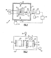
- Figure 1 illustrates selected portions of an example electron beam vapor deposition apparatus 10 (hereafter "the deposition apparatus 10") for coating a work piece 12 (or work pieces 12), such as airfoils or paired turbine vanes of a gas turbine engine.
- the work piece 12 may include surfaces that are difficult to coat with a desired coating microstructural orientation because the geometry of the work piece 12. That is, the work piece 12 may have angled or curved surfaces and/or surfaces having low clearance relative to another surface.
- turbine vane segments for example, which have angled fillet surfaces with the platform and airfoils with a relatively small gap therebetween.
- the example deposition apparatus 10 is not limited to use for any particular type of work piece 12.
- the type of coating deposited onto the work piece 12 may be any coating that is suitable for vapor deposition, such as metallic coatings or ceramic coatings.
- the coating may be a ceramic thermal barrier coating that includes gadolinia, zirconia, yttria, or combinations thereof.
- the deposition apparatus 10 includes a coating chamber 14 for containing the work pieces 12 during a coating operation and establishing desirable coating conditions.
- the coating chamber 14 may be a vacuum chamber and may include various ports for evacuating the interior or for selectively introducing process gases.
- a gas source 16 may provide a desired flow of oxygen or other process gas into the coating chamber 14.
- a pump 18 may circulate a coolant (e.g., water) through walls of the coating chamber 14 to control wall temperature.
- a coolant e.g., water
- the work piece 12 may be pre-heated prior to insertion into the coating chamber 14 to form a thermally grown oxide on the work piece 12.
- the oxide is intended to enhance adhesion of the coating on the work piece 12.
- At least one electron beam source 20 such as an electron gun, is mounted relative to the coating chamber 14 for melting and evaporating a source coating material 34, such as an ingot.
- a source coating material 34 such as an ingot.
- two electron beam sources 20 are shown; however, the deposition apparatus 10 may alternatively include a single electron beam source 20 or more than two electron beam sources 20. Given this description, one of ordinary skill in the art will recognize an appropriate number of the electron beam sources 20 to meet their particular needs.
- a transport 22 is configured to hold and move the work piece 12 back and forth in direction 24 to move the work piece 12 in and out of the coating chamber 14 and in and out of a coating zone 26 where the work piece 12 is to be coated.
- the coating zone 26 may be the spatial volume in the coating chamber 14 where the work piece 12 is coated.
- the transport 22 includes a shaft 28 that may be adapted to receive one or more fixtures that hold one or more of the work pieces 12. The shaft 28 may be translated in a known manner using a motor, actuator, or the like.
- a coating device 30 is located near the coating zone 26, such as below the coating zone 26, and includes at least one crucible 32 for presenting at least one source coating material 34 that is to be deposited onto the work piece 12.
- the coating device 30 may include a single crucible that is used for different deposition modes of the deposition apparatus 10.
- the coating device 30 may include multiple crucibles 32 that correspond to different deposition modes, as will be described below.
- a desirable stand-off distance may be established between the coating device 30 and the coating zone 26 and/or work piece 12, depending on the geometry of the work piece 12, settings of the electron beam source(s) 20, and other factors.
- the deposition apparatus 10 may also include a thermal hood (not shown) arranged near the coating zone 26 to facilitate temperature control.
- a thermal hood is disclosed in application co-pending and commonly-owned serial 12/196,368 entitled “DEPOSITION APPARATUS HAVING THERMAL HOOD”.
- a controller 36 is in communication with the transport 22 and, optionally, the electron beam source 20 and possibly other components of the deposition apparatus 10 to control the operation thereof.
- the controller 36 may include software, hardware, or both for operating the deposition apparatus 10.
- the controller 36 may be configured to control movement of the work piece 12 in and out of the coating chamber 14 into the coating zone 26 and movement of the work piece 12 within the coating zone 26 during a coating operation.
- the coating device 30 may also include one or more gas sources 38.
- the gas sources 38 may correspond to different deposition modes of the deposition apparatus 10.
- the coating device 30 includes a first deposition mode of depositing the source coating material 34 onto the work piece 12 and a second deposition mode for depositing the source coating material 34 onto the work piece 12.
- the first and second deposition modes correspond to different deposition techniques, such as physical vapor deposition (PVD) and directed vapor deposition (DVD). That is, the coating device 30 may be configured for physical vapor deposition during one portion of a coating cycle and for directed vapor deposition mode in another portion of the coating cycle.
- the deposition apparatus 10 is not limited to using a single deposition technique and may be utilized to cost effectively use multiple deposition techniques. That is, a more expensive technique, such as DVD, can be used to coat only the non-line-of-sight surfaces while a less expensive technique, such as PVD, can be used to coat line-of-sight surfaces.
- the controller 36 is configured to control a speed of movement of the work piece 12 in the coating zone 26 during a coating cycle in response to the first deposition mode and the second deposition mode. For instance, the controller 36 may change the speed of movement of the work piece 12 depending upon whether the coating device 30 is in the first deposition mode or the second deposition mode.
- the speed of movement may refer to the rotational speed of the work piece 12 in revolutions per minute while in the coating zone 26.
- the controller 36 may move the work piece 12 using the transport 22 at a first speed when the coating device 30 is in the first deposition mode and at a second, different speed for the second deposition mode.
- the speed may be relatively fast to coat line-of-sight surfaces of the work piece 12.
- the speed may be relatively slow or static to facilitate depositing the coating on non-line-of-sight surfaces of the work piece 12, which may require longer coatings times than line-of-sight surfaces.
- the controller 36 may change the speed of movement of the work piece 12 in conjunction with switching between the deposition modes depending on whether the deposition apparatus 10 is coating a line-of-sight surface or a non-line-of-sight surface of the work piece 12.
- the controller 36 may also control supply of gas flow from the one or more gas sources 38 to the coating device 30 depending on the deposition mode.
- the coating device 30 may utilize a first type of gas from one of the gas sources 38 when in the first deposition mode and a second type of gas flow from another of the gas sources 38 when in the second deposition mode.
- the coating device 30 may utilize a first gas flow rate for one of the deposition modes a second, different gas flow rate for the other deposition mode.
- the coating device 30 may not utilize any gas for one of the deposition modes and may use gas in the other deposition mode.
- the PVD mode may use no gas or a relatively low flow rate of gas (compared to DVD), and the DVD mode uses gas as a carrier of evaporated source coating material 34.
- FIG. 2 illustrates an example of a coating device 130 that may be used in the deposition apparatus 10.
- the coating device 130 is adapted for PVD deposition and DVD deposition.
- the coating device 30 includes a PVD crucible 50 and a DVD crucible 52.
- the PVD crucible 50 includes a cylindrical wall that contains the source coating material 34, which may be connected to an actuator in a known manner for moving the source coating material 34 as it is consumed in the coating process.
- the PVD crucible 50 is not connected to any of the gas sources 38.
- the PVD crucible 50 may be connected to one of the gas sources 38 for providing a relatively low flow of gas through or near the PVD crucible 50.
Landscapes
- Chemical & Material Sciences (AREA)
- Engineering & Computer Science (AREA)
- Materials Engineering (AREA)
- Analytical Chemistry (AREA)
- Chemical Kinetics & Catalysis (AREA)
- Mechanical Engineering (AREA)
- Metallurgy (AREA)
- Organic Chemistry (AREA)
- Plasma & Fusion (AREA)
- Physics & Mathematics (AREA)
- Health & Medical Sciences (AREA)
- Toxicology (AREA)
- Physical Vapour Deposition (AREA)
Applications Claiming Priority (1)
| Application Number | Priority Date | Filing Date | Title |
|---|---|---|---|
| US12/414,697 US8419857B2 (en) | 2009-03-31 | 2009-03-31 | Electron beam vapor deposition apparatus and method of coating |
Publications (2)
| Publication Number | Publication Date |
|---|---|
| EP2236643A2 true EP2236643A2 (de) | 2010-10-06 |
| EP2236643A3 EP2236643A3 (de) | 2011-01-19 |
Family
ID=42270065
Family Applications (1)
| Application Number | Title | Priority Date | Filing Date |
|---|---|---|---|
| EP10250662A Withdrawn EP2236643A3 (de) | 2009-03-31 | 2010-03-30 | Vorrichtung zur Elektronenstrahl-Dampfabscheidung und Beschichtungsverfahren |
Country Status (3)
| Country | Link |
|---|---|
| US (1) | US8419857B2 (de) |
| EP (1) | EP2236643A3 (de) |
| SG (1) | SG165297A1 (de) |
Cited By (2)
| Publication number | Priority date | Publication date | Assignee | Title |
|---|---|---|---|---|
| DE102017100507A1 (de) | 2017-01-12 | 2018-07-12 | Ald Vacuum Technologies Gmbh | Vorrichtung und Verfahren zur Beschichtung von Werkstücken |
| EP3719168A1 (de) * | 2019-04-05 | 2020-10-07 | Raytheon Technologies Corporation | Elektronenstrahl-dampfabscheidungsverfahren und -vorrichtung |
Families Citing this family (5)
| Publication number | Priority date | Publication date | Assignee | Title |
|---|---|---|---|---|
| US8951350B2 (en) | 2011-05-03 | 2015-02-10 | United Technologies Corporation | Coating methods and apparatus |
| US10145006B2 (en) * | 2014-01-20 | 2018-12-04 | United Technologies Corporation | Physical vapor deposition using rotational speed selected with respect to deposition rate |
| WO2015112583A1 (en) | 2014-01-21 | 2015-07-30 | United Technologies Corporation | Method for forming single crystal components using additive manufacturing and re-melt |
| US10724133B2 (en) | 2016-09-14 | 2020-07-28 | Raytheon Technologies Corporation | EBPVD columnated vapor stream |
| US10643821B2 (en) | 2017-02-07 | 2020-05-05 | United Technologies Corporation | Part temperature measurement device |
Citations (1)
| Publication number | Priority date | Publication date | Assignee | Title |
|---|---|---|---|---|
| WO1999065626A1 (en) | 1998-06-16 | 1999-12-23 | University Of Virginia Patent Foundation | Apparatus and method for producing thermal barrier coatings |
Family Cites Families (27)
| Publication number | Priority date | Publication date | Assignee | Title |
|---|---|---|---|---|
| US4153005A (en) * | 1977-07-06 | 1979-05-08 | United Technologies Corporation | Multiple electron beam vacuum vapor deposition apparatus |
| US5601652A (en) * | 1989-08-03 | 1997-02-11 | United Technologies Corporation | Apparatus for applying ceramic coatings |
| US5087477A (en) * | 1990-02-05 | 1992-02-11 | United Technologies Corporation | Eb-pvd method for applying ceramic coatings |
| JPH0793193B2 (ja) * | 1990-05-30 | 1995-10-09 | シャープ株式会社 | 薄膜el素子の製造方法 |
| DE4412906C1 (de) * | 1994-04-14 | 1995-07-13 | Fraunhofer Ges Forschung | Verfahren und Einrichtung für die ionengestützte Vakuumbeschichtung |
| US5534314A (en) * | 1994-08-31 | 1996-07-09 | University Of Virginia Patent Foundation | Directed vapor deposition of electron beam evaporant |
| JPH09293239A (ja) | 1996-04-22 | 1997-11-11 | Sony Corp | 金属磁性薄膜型磁気記録媒体の製造方法 |
| DE59702062D1 (de) * | 1996-05-30 | 2000-08-24 | Siemens Ag | Beschichtungsvorrichtung und verfahren zur beschichtung eines bauteils mit einer wärmedämmschicht |
| US5736073A (en) * | 1996-07-08 | 1998-04-07 | University Of Virginia Patent Foundation | Production of nanometer particles by directed vapor deposition of electron beam evaporant |
| US5932078A (en) * | 1997-08-30 | 1999-08-03 | United Technologies Corporation | Cathodic arc vapor deposition apparatus |
| SG71151A1 (en) * | 1997-09-17 | 2000-03-21 | Gen Electric | Bond coat for a thermal barrier coating system and method therefor |
| US6172331B1 (en) * | 1997-09-17 | 2001-01-09 | General Electric Company | Method and apparatus for laser drilling |
| US6042898A (en) * | 1998-12-15 | 2000-03-28 | United Technologies Corporation | Method for applying improved durability thermal barrier coatings |
| WO2002087787A1 (en) * | 2001-04-30 | 2002-11-07 | University Of Virginia Patent Foundation | Method and apparatus for efficient application of substrate coating |
| US8124178B2 (en) | 2001-09-10 | 2012-02-28 | University Of Virginia Patent Foundation | Method and apparatus application of metallic alloy coatings |
| JP2003133230A (ja) * | 2001-10-29 | 2003-05-09 | Mitsubishi Heavy Ind Ltd | フレキシブル基板の半導体処理装置 |
| EP1509633B1 (de) * | 2002-04-25 | 2015-12-02 | University Of Virginia Patent Foundation | Verfahren zur schnellen einheitlichen beschichtung auch ohne sichtverbindung |
| US20060062912A1 (en) * | 2002-11-21 | 2006-03-23 | Wortman David J | Bond coat for a thermal barrier coating system and related method thereof |
| JP2005088431A (ja) | 2003-09-18 | 2005-04-07 | Dainippon Printing Co Ltd | バリア性フィルム |
| WO2005089107A2 (en) * | 2004-01-08 | 2005-09-29 | University Of Virginia Patent Foundation | Apparatus and method for applying coatings onto the interior surfaces of components and related structures produced therefrom |
| DE102004042650B4 (de) | 2004-09-03 | 2007-07-19 | Fraunhofer-Gesellschaft zur Förderung der angewandten Forschung e.V. | Verfahren zum Abscheiden von photokatalytischen Titanoxid-Schichten |
| US7329436B2 (en) * | 2004-11-17 | 2008-02-12 | United Technologies Corporation | Vapor deposition of dissimilar materials |
| WO2007005832A2 (en) | 2005-06-30 | 2007-01-11 | University Of Virginia Patent Foundation | Reliant thermal barrier coating system and related methods and apparatus of making the same |
| CN101144149B (zh) | 2006-09-11 | 2010-12-22 | 柏腾科技股份有限公司 | 无时间延迟的连续式真空制程设备及真空加工方法 |
| US20080160171A1 (en) * | 2006-12-29 | 2008-07-03 | United Technologies Corporation | Electron beam physical vapor deposition apparatus and processes for adjusting the feed rate of a target and manufacturing a multi-component condensate free of lamination |
| US7997227B2 (en) | 2007-03-13 | 2011-08-16 | General Electric Company | Vacuum coater device and mechanism for supporting and manipulating workpieces in same |
| US8404047B2 (en) | 2008-09-16 | 2013-03-26 | United Technologies Corporation | Electron beam vapor deposition apparatus and method |
-
2009
- 2009-03-31 US US12/414,697 patent/US8419857B2/en active Active
-
2010
- 2010-03-30 EP EP10250662A patent/EP2236643A3/de not_active Withdrawn
- 2010-03-30 SG SG201002217-6A patent/SG165297A1/en unknown
Patent Citations (1)
| Publication number | Priority date | Publication date | Assignee | Title |
|---|---|---|---|---|
| WO1999065626A1 (en) | 1998-06-16 | 1999-12-23 | University Of Virginia Patent Foundation | Apparatus and method for producing thermal barrier coatings |
Non-Patent Citations (1)
| Title |
|---|
| YANG H Q ET AL.: "Dual electron beam evaporator for the preparation of composition-modulated structures", JOURNAL OF VACUUM SCIENCE & TECHNOLOGY A, vol. 2, no. 1, January 1984 (1984-01-01), pages 1 - 4 |
Cited By (5)
| Publication number | Priority date | Publication date | Assignee | Title |
|---|---|---|---|---|
| DE102017100507A1 (de) | 2017-01-12 | 2018-07-12 | Ald Vacuum Technologies Gmbh | Vorrichtung und Verfahren zur Beschichtung von Werkstücken |
| EP3348666A1 (de) | 2017-01-12 | 2018-07-18 | ALD Vacuum Technologies GmbH | Vorrichtung und verfahren zur beschichtung von werkstücken |
| DE102017100507B4 (de) | 2017-01-12 | 2021-11-25 | Ald Vacuum Technologies Gmbh | Vorrichtung und Verfahren zur Beschichtung von Werkstücken |
| US11795542B2 (en) | 2017-01-12 | 2023-10-24 | Ald Vacuum Technologies Gmbh | Apparatus and method for coating workpieces |
| EP3719168A1 (de) * | 2019-04-05 | 2020-10-07 | Raytheon Technologies Corporation | Elektronenstrahl-dampfabscheidungsverfahren und -vorrichtung |
Also Published As
| Publication number | Publication date |
|---|---|
| SG165297A1 (en) | 2010-10-28 |
| US8419857B2 (en) | 2013-04-16 |
| US20100242841A1 (en) | 2010-09-30 |
| EP2236643A3 (de) | 2011-01-19 |
Similar Documents
| Publication | Publication Date | Title |
|---|---|---|
| US8419857B2 (en) | Electron beam vapor deposition apparatus and method of coating | |
| EP2261387B1 (de) | Elektronenstrahl-Dampfabscheidungsvorrichtung zur Abscheidung einer Mehrlagenbeschichtung | |
| US8506715B2 (en) | Coating deposition apparatus and method therefor | |
| US8084086B2 (en) | Reliant thermal barrier coating system and related methods and apparatus of making the same | |
| US20090162670A1 (en) | Method for applying ceramic coatings to smooth surfaces by air plasma spray techniques, and related articles | |
| EP2213762B1 (de) | Beschichtungsvorrichtung und ablagerungsvorrichtung | |
| US20120231211A1 (en) | Method for the manufacture of a thermal barrier coating structure | |
| EP3943641A1 (de) | Cmas-beständige thermische barrierebeschichtung für einen teil eines gasturbinenmotors | |
| EP2166127B1 (de) | Vorrichtung und Verfahren zur Elektronenstrahl-Dampfabscheidung | |
| US20140193760A1 (en) | Coated article, process of coating an article, and method of using a coated article | |
| US9249514B2 (en) | Article formed by plasma spray | |
| EP1895022B1 (de) | Verbessertes Nicht-Sichtverbindungs-Beschichtungsverfahren | |
| US6145470A (en) | Apparatus for electron beam physical vapor deposition | |
| US11542593B2 (en) | Nanoparticle formation mitigation in a deposition process | |
| US20190040525A1 (en) | Physical vapor deposition using rotational speed selected with respect to deposition rate | |
| EP3296421B1 (de) | Eb-pvd-säulenförmiger dampfstrom | |
| EP3719168B1 (de) | Elektronenstrahl-dampfabscheidungsverfahren | |
| EP3106538B1 (de) | Gleichmässig dicke wärmedämmschicht für nichtvisierlinien- und visierlinienbereiche | |
| EP1074638A1 (de) | Verfahren zum Beschichten eines Gegenstandes |
Legal Events
| Date | Code | Title | Description |
|---|---|---|---|
| PUAI | Public reference made under article 153(3) epc to a published international application that has entered the european phase |
Free format text: ORIGINAL CODE: 0009012 |
|
| AK | Designated contracting states |
Kind code of ref document: A2 Designated state(s): AT BE BG CH CY CZ DE DK EE ES FI FR GB GR HR HU IE IS IT LI LT LU LV MC MK MT NL NO PL PT RO SE SI SK SM TR |
|
| AX | Request for extension of the european patent |
Extension state: AL BA ME RS |
|
| PUAL | Search report despatched |
Free format text: ORIGINAL CODE: 0009013 |
|
| RIC1 | Information provided on ipc code assigned before grant |
Ipc: C23C 14/04 20060101ALI20101208BHEP Ipc: H01J 37/317 20060101ALI20101208BHEP Ipc: H01J 37/305 20060101ALI20101208BHEP Ipc: H01J 37/16 20060101ALI20101208BHEP Ipc: C23C 14/30 20060101AFI20100804BHEP |
|
| AK | Designated contracting states |
Kind code of ref document: A3 Designated state(s): AT BE BG CH CY CZ DE DK EE ES FI FR GB GR HR HU IE IS IT LI LT LU LV MC MK MT NL NO PL PT RO SE SI SK SM TR |
|
| AX | Request for extension of the european patent |
Extension state: AL BA ME RS |
|
| 17P | Request for examination filed |
Effective date: 20110718 |
|
| STAA | Information on the status of an ep patent application or granted ep patent |
Free format text: STATUS: THE APPLICATION HAS BEEN WITHDRAWN |
|
| 18W | Application withdrawn |
Effective date: 20131216 |