EP2236374A1 - Control apparatus for hybrid vehicle - Google Patents
Control apparatus for hybrid vehicle Download PDFInfo
- Publication number
- EP2236374A1 EP2236374A1 EP10156274A EP10156274A EP2236374A1 EP 2236374 A1 EP2236374 A1 EP 2236374A1 EP 10156274 A EP10156274 A EP 10156274A EP 10156274 A EP10156274 A EP 10156274A EP 2236374 A1 EP2236374 A1 EP 2236374A1
- Authority
- EP
- European Patent Office
- Prior art keywords
- drive mode
- engagement element
- engine
- motor
- vehicle
- Prior art date
- Legal status (The legal status is an assumption and is not a legal conclusion. Google has not performed a legal analysis and makes no representation as to the accuracy of the status listed.)
- Granted
Links
Images


Classifications
-
- B—PERFORMING OPERATIONS; TRANSPORTING
- B60—VEHICLES IN GENERAL
- B60W—CONJOINT CONTROL OF VEHICLE SUB-UNITS OF DIFFERENT TYPE OR DIFFERENT FUNCTION; CONTROL SYSTEMS SPECIALLY ADAPTED FOR HYBRID VEHICLES; ROAD VEHICLE DRIVE CONTROL SYSTEMS FOR PURPOSES NOT RELATED TO THE CONTROL OF A PARTICULAR SUB-UNIT
- B60W20/00—Control systems specially adapted for hybrid vehicles
- B60W20/40—Controlling the engagement or disengagement of prime movers, e.g. for transition between prime movers
-
- B—PERFORMING OPERATIONS; TRANSPORTING
- B60—VEHICLES IN GENERAL
- B60W—CONJOINT CONTROL OF VEHICLE SUB-UNITS OF DIFFERENT TYPE OR DIFFERENT FUNCTION; CONTROL SYSTEMS SPECIALLY ADAPTED FOR HYBRID VEHICLES; ROAD VEHICLE DRIVE CONTROL SYSTEMS FOR PURPOSES NOT RELATED TO THE CONTROL OF A PARTICULAR SUB-UNIT
- B60W10/00—Conjoint control of vehicle sub-units of different type or different function
- B60W10/04—Conjoint control of vehicle sub-units of different type or different function including control of propulsion units
-
- B—PERFORMING OPERATIONS; TRANSPORTING
- B60—VEHICLES IN GENERAL
- B60K—ARRANGEMENT OR MOUNTING OF PROPULSION UNITS OR OF TRANSMISSIONS IN VEHICLES; ARRANGEMENT OR MOUNTING OF PLURAL DIVERSE PRIME-MOVERS IN VEHICLES; AUXILIARY DRIVES FOR VEHICLES; INSTRUMENTATION OR DASHBOARDS FOR VEHICLES; ARRANGEMENTS IN CONNECTION WITH COOLING, AIR INTAKE, GAS EXHAUST OR FUEL SUPPLY OF PROPULSION UNITS IN VEHICLES
- B60K6/00—Arrangement or mounting of plural diverse prime-movers for mutual or common propulsion, e.g. hybrid propulsion systems comprising electric motors and internal combustion engines ; Control systems therefor, i.e. systems controlling two or more prime movers, or controlling one of these prime movers and any of the transmission, drive or drive units Informative references: mechanical gearings with secondary electric drive F16H3/72; arrangements for handling mechanical energy structurally associated with the dynamo-electric machine H02K7/00; machines comprising structurally interrelated motor and generator parts H02K51/00; dynamo-electric machines not otherwise provided for in H02K see H02K99/00
- B60K6/20—Arrangement or mounting of plural diverse prime-movers for mutual or common propulsion, e.g. hybrid propulsion systems comprising electric motors and internal combustion engines ; Control systems therefor, i.e. systems controlling two or more prime movers, or controlling one of these prime movers and any of the transmission, drive or drive units Informative references: mechanical gearings with secondary electric drive F16H3/72; arrangements for handling mechanical energy structurally associated with the dynamo-electric machine H02K7/00; machines comprising structurally interrelated motor and generator parts H02K51/00; dynamo-electric machines not otherwise provided for in H02K see H02K99/00 the prime-movers consisting of electric motors and internal combustion engines, e.g. HEVs
- B60K6/22—Arrangement or mounting of plural diverse prime-movers for mutual or common propulsion, e.g. hybrid propulsion systems comprising electric motors and internal combustion engines ; Control systems therefor, i.e. systems controlling two or more prime movers, or controlling one of these prime movers and any of the transmission, drive or drive units Informative references: mechanical gearings with secondary electric drive F16H3/72; arrangements for handling mechanical energy structurally associated with the dynamo-electric machine H02K7/00; machines comprising structurally interrelated motor and generator parts H02K51/00; dynamo-electric machines not otherwise provided for in H02K see H02K99/00 the prime-movers consisting of electric motors and internal combustion engines, e.g. HEVs characterised by apparatus, components or means specially adapted for HEVs
-
- B—PERFORMING OPERATIONS; TRANSPORTING
- B60—VEHICLES IN GENERAL
- B60K—ARRANGEMENT OR MOUNTING OF PROPULSION UNITS OR OF TRANSMISSIONS IN VEHICLES; ARRANGEMENT OR MOUNTING OF PLURAL DIVERSE PRIME-MOVERS IN VEHICLES; AUXILIARY DRIVES FOR VEHICLES; INSTRUMENTATION OR DASHBOARDS FOR VEHICLES; ARRANGEMENTS IN CONNECTION WITH COOLING, AIR INTAKE, GAS EXHAUST OR FUEL SUPPLY OF PROPULSION UNITS IN VEHICLES
- B60K6/00—Arrangement or mounting of plural diverse prime-movers for mutual or common propulsion, e.g. hybrid propulsion systems comprising electric motors and internal combustion engines ; Control systems therefor, i.e. systems controlling two or more prime movers, or controlling one of these prime movers and any of the transmission, drive or drive units Informative references: mechanical gearings with secondary electric drive F16H3/72; arrangements for handling mechanical energy structurally associated with the dynamo-electric machine H02K7/00; machines comprising structurally interrelated motor and generator parts H02K51/00; dynamo-electric machines not otherwise provided for in H02K see H02K99/00
- B60K6/20—Arrangement or mounting of plural diverse prime-movers for mutual or common propulsion, e.g. hybrid propulsion systems comprising electric motors and internal combustion engines ; Control systems therefor, i.e. systems controlling two or more prime movers, or controlling one of these prime movers and any of the transmission, drive or drive units Informative references: mechanical gearings with secondary electric drive F16H3/72; arrangements for handling mechanical energy structurally associated with the dynamo-electric machine H02K7/00; machines comprising structurally interrelated motor and generator parts H02K51/00; dynamo-electric machines not otherwise provided for in H02K see H02K99/00 the prime-movers consisting of electric motors and internal combustion engines, e.g. HEVs
- B60K6/42—Arrangement or mounting of plural diverse prime-movers for mutual or common propulsion, e.g. hybrid propulsion systems comprising electric motors and internal combustion engines ; Control systems therefor, i.e. systems controlling two or more prime movers, or controlling one of these prime movers and any of the transmission, drive or drive units Informative references: mechanical gearings with secondary electric drive F16H3/72; arrangements for handling mechanical energy structurally associated with the dynamo-electric machine H02K7/00; machines comprising structurally interrelated motor and generator parts H02K51/00; dynamo-electric machines not otherwise provided for in H02K see H02K99/00 the prime-movers consisting of electric motors and internal combustion engines, e.g. HEVs characterised by the architecture of the hybrid electric vehicle
- B60K6/48—Parallel type
-
- B—PERFORMING OPERATIONS; TRANSPORTING
- B60—VEHICLES IN GENERAL
- B60L—PROPULSION OF ELECTRICALLY-PROPELLED VEHICLES; SUPPLYING ELECTRIC POWER FOR AUXILIARY EQUIPMENT OF ELECTRICALLY-PROPELLED VEHICLES; ELECTRODYNAMIC BRAKE SYSTEMS FOR VEHICLES IN GENERAL; MAGNETIC SUSPENSION OR LEVITATION FOR VEHICLES; MONITORING OPERATING VARIABLES OF ELECTRICALLY-PROPELLED VEHICLES; ELECTRIC SAFETY DEVICES FOR ELECTRICALLY-PROPELLED VEHICLES
- B60L15/00—Methods, circuits, or devices for controlling the traction-motor speed of electrically-propelled vehicles
- B60L15/20—Methods, circuits, or devices for controlling the traction-motor speed of electrically-propelled vehicles for control of the vehicle or its driving motor to achieve a desired performance, e.g. speed, torque, programmed variation of speed
- B60L15/2054—Methods, circuits, or devices for controlling the traction-motor speed of electrically-propelled vehicles for control of the vehicle or its driving motor to achieve a desired performance, e.g. speed, torque, programmed variation of speed by controlling transmissions or clutches
-
- B—PERFORMING OPERATIONS; TRANSPORTING
- B60—VEHICLES IN GENERAL
- B60L—PROPULSION OF ELECTRICALLY-PROPELLED VEHICLES; SUPPLYING ELECTRIC POWER FOR AUXILIARY EQUIPMENT OF ELECTRICALLY-PROPELLED VEHICLES; ELECTRODYNAMIC BRAKE SYSTEMS FOR VEHICLES IN GENERAL; MAGNETIC SUSPENSION OR LEVITATION FOR VEHICLES; MONITORING OPERATING VARIABLES OF ELECTRICALLY-PROPELLED VEHICLES; ELECTRIC SAFETY DEVICES FOR ELECTRICALLY-PROPELLED VEHICLES
- B60L50/00—Electric propulsion with power supplied within the vehicle
- B60L50/10—Electric propulsion with power supplied within the vehicle using propulsion power supplied by engine-driven generators, e.g. generators driven by combustion engines
- B60L50/16—Electric propulsion with power supplied within the vehicle using propulsion power supplied by engine-driven generators, e.g. generators driven by combustion engines with provision for separate direct mechanical propulsion
-
- B—PERFORMING OPERATIONS; TRANSPORTING
- B60—VEHICLES IN GENERAL
- B60W—CONJOINT CONTROL OF VEHICLE SUB-UNITS OF DIFFERENT TYPE OR DIFFERENT FUNCTION; CONTROL SYSTEMS SPECIALLY ADAPTED FOR HYBRID VEHICLES; ROAD VEHICLE DRIVE CONTROL SYSTEMS FOR PURPOSES NOT RELATED TO THE CONTROL OF A PARTICULAR SUB-UNIT
- B60W10/00—Conjoint control of vehicle sub-units of different type or different function
- B60W10/02—Conjoint control of vehicle sub-units of different type or different function including control of driveline clutches
-
- B—PERFORMING OPERATIONS; TRANSPORTING
- B60—VEHICLES IN GENERAL
- B60W—CONJOINT CONTROL OF VEHICLE SUB-UNITS OF DIFFERENT TYPE OR DIFFERENT FUNCTION; CONTROL SYSTEMS SPECIALLY ADAPTED FOR HYBRID VEHICLES; ROAD VEHICLE DRIVE CONTROL SYSTEMS FOR PURPOSES NOT RELATED TO THE CONTROL OF A PARTICULAR SUB-UNIT
- B60W10/00—Conjoint control of vehicle sub-units of different type or different function
- B60W10/04—Conjoint control of vehicle sub-units of different type or different function including control of propulsion units
- B60W10/06—Conjoint control of vehicle sub-units of different type or different function including control of propulsion units including control of combustion engines
-
- B—PERFORMING OPERATIONS; TRANSPORTING
- B60—VEHICLES IN GENERAL
- B60W—CONJOINT CONTROL OF VEHICLE SUB-UNITS OF DIFFERENT TYPE OR DIFFERENT FUNCTION; CONTROL SYSTEMS SPECIALLY ADAPTED FOR HYBRID VEHICLES; ROAD VEHICLE DRIVE CONTROL SYSTEMS FOR PURPOSES NOT RELATED TO THE CONTROL OF A PARTICULAR SUB-UNIT
- B60W10/00—Conjoint control of vehicle sub-units of different type or different function
- B60W10/04—Conjoint control of vehicle sub-units of different type or different function including control of propulsion units
- B60W10/08—Conjoint control of vehicle sub-units of different type or different function including control of propulsion units including control of electric propulsion units, e.g. motors or generators
-
- B—PERFORMING OPERATIONS; TRANSPORTING
- B60—VEHICLES IN GENERAL
- B60W—CONJOINT CONTROL OF VEHICLE SUB-UNITS OF DIFFERENT TYPE OR DIFFERENT FUNCTION; CONTROL SYSTEMS SPECIALLY ADAPTED FOR HYBRID VEHICLES; ROAD VEHICLE DRIVE CONTROL SYSTEMS FOR PURPOSES NOT RELATED TO THE CONTROL OF A PARTICULAR SUB-UNIT
- B60W30/00—Purposes of road vehicle drive control systems not related to the control of a particular sub-unit, e.g. of systems using conjoint control of vehicle sub-units, or advanced driver assistance systems for ensuring comfort, stability and safety or drive control systems for propelling or retarding the vehicle
- B60W30/18—Propelling the vehicle
- B60W30/18009—Propelling the vehicle related to particular drive situations
- B60W30/18027—Drive off, accelerating from standstill
-
- B—PERFORMING OPERATIONS; TRANSPORTING
- B60—VEHICLES IN GENERAL
- B60W—CONJOINT CONTROL OF VEHICLE SUB-UNITS OF DIFFERENT TYPE OR DIFFERENT FUNCTION; CONTROL SYSTEMS SPECIALLY ADAPTED FOR HYBRID VEHICLES; ROAD VEHICLE DRIVE CONTROL SYSTEMS FOR PURPOSES NOT RELATED TO THE CONTROL OF A PARTICULAR SUB-UNIT
- B60W30/00—Purposes of road vehicle drive control systems not related to the control of a particular sub-unit, e.g. of systems using conjoint control of vehicle sub-units, or advanced driver assistance systems for ensuring comfort, stability and safety or drive control systems for propelling or retarding the vehicle
- B60W30/18—Propelling the vehicle
- B60W30/184—Preventing damage resulting from overload or excessive wear of the driveline
- B60W30/186—Preventing damage resulting from overload or excessive wear of the driveline excessive wear or burn out of friction elements, e.g. clutches
-
- B—PERFORMING OPERATIONS; TRANSPORTING
- B60—VEHICLES IN GENERAL
- B60L—PROPULSION OF ELECTRICALLY-PROPELLED VEHICLES; SUPPLYING ELECTRIC POWER FOR AUXILIARY EQUIPMENT OF ELECTRICALLY-PROPELLED VEHICLES; ELECTRODYNAMIC BRAKE SYSTEMS FOR VEHICLES IN GENERAL; MAGNETIC SUSPENSION OR LEVITATION FOR VEHICLES; MONITORING OPERATING VARIABLES OF ELECTRICALLY-PROPELLED VEHICLES; ELECTRIC SAFETY DEVICES FOR ELECTRICALLY-PROPELLED VEHICLES
- B60L2240/00—Control parameters of input or output; Target parameters
- B60L2240/10—Vehicle control parameters
- B60L2240/12—Speed
-
- B—PERFORMING OPERATIONS; TRANSPORTING
- B60—VEHICLES IN GENERAL
- B60L—PROPULSION OF ELECTRICALLY-PROPELLED VEHICLES; SUPPLYING ELECTRIC POWER FOR AUXILIARY EQUIPMENT OF ELECTRICALLY-PROPELLED VEHICLES; ELECTRODYNAMIC BRAKE SYSTEMS FOR VEHICLES IN GENERAL; MAGNETIC SUSPENSION OR LEVITATION FOR VEHICLES; MONITORING OPERATING VARIABLES OF ELECTRICALLY-PROPELLED VEHICLES; ELECTRIC SAFETY DEVICES FOR ELECTRICALLY-PROPELLED VEHICLES
- B60L2240/00—Control parameters of input or output; Target parameters
- B60L2240/10—Vehicle control parameters
- B60L2240/36—Temperature of vehicle components or parts
-
- B—PERFORMING OPERATIONS; TRANSPORTING
- B60—VEHICLES IN GENERAL
- B60L—PROPULSION OF ELECTRICALLY-PROPELLED VEHICLES; SUPPLYING ELECTRIC POWER FOR AUXILIARY EQUIPMENT OF ELECTRICALLY-PROPELLED VEHICLES; ELECTRODYNAMIC BRAKE SYSTEMS FOR VEHICLES IN GENERAL; MAGNETIC SUSPENSION OR LEVITATION FOR VEHICLES; MONITORING OPERATING VARIABLES OF ELECTRICALLY-PROPELLED VEHICLES; ELECTRIC SAFETY DEVICES FOR ELECTRICALLY-PROPELLED VEHICLES
- B60L2240/00—Control parameters of input or output; Target parameters
- B60L2240/40—Drive Train control parameters
- B60L2240/42—Drive Train control parameters related to electric machines
- B60L2240/421—Speed
-
- B—PERFORMING OPERATIONS; TRANSPORTING
- B60—VEHICLES IN GENERAL
- B60L—PROPULSION OF ELECTRICALLY-PROPELLED VEHICLES; SUPPLYING ELECTRIC POWER FOR AUXILIARY EQUIPMENT OF ELECTRICALLY-PROPELLED VEHICLES; ELECTRODYNAMIC BRAKE SYSTEMS FOR VEHICLES IN GENERAL; MAGNETIC SUSPENSION OR LEVITATION FOR VEHICLES; MONITORING OPERATING VARIABLES OF ELECTRICALLY-PROPELLED VEHICLES; ELECTRIC SAFETY DEVICES FOR ELECTRICALLY-PROPELLED VEHICLES
- B60L2240/00—Control parameters of input or output; Target parameters
- B60L2240/40—Drive Train control parameters
- B60L2240/42—Drive Train control parameters related to electric machines
- B60L2240/423—Torque
-
- B—PERFORMING OPERATIONS; TRANSPORTING
- B60—VEHICLES IN GENERAL
- B60L—PROPULSION OF ELECTRICALLY-PROPELLED VEHICLES; SUPPLYING ELECTRIC POWER FOR AUXILIARY EQUIPMENT OF ELECTRICALLY-PROPELLED VEHICLES; ELECTRODYNAMIC BRAKE SYSTEMS FOR VEHICLES IN GENERAL; MAGNETIC SUSPENSION OR LEVITATION FOR VEHICLES; MONITORING OPERATING VARIABLES OF ELECTRICALLY-PROPELLED VEHICLES; ELECTRIC SAFETY DEVICES FOR ELECTRICALLY-PROPELLED VEHICLES
- B60L2240/00—Control parameters of input or output; Target parameters
- B60L2240/40—Drive Train control parameters
- B60L2240/44—Drive Train control parameters related to combustion engines
- B60L2240/441—Speed
-
- B—PERFORMING OPERATIONS; TRANSPORTING
- B60—VEHICLES IN GENERAL
- B60L—PROPULSION OF ELECTRICALLY-PROPELLED VEHICLES; SUPPLYING ELECTRIC POWER FOR AUXILIARY EQUIPMENT OF ELECTRICALLY-PROPELLED VEHICLES; ELECTRODYNAMIC BRAKE SYSTEMS FOR VEHICLES IN GENERAL; MAGNETIC SUSPENSION OR LEVITATION FOR VEHICLES; MONITORING OPERATING VARIABLES OF ELECTRICALLY-PROPELLED VEHICLES; ELECTRIC SAFETY DEVICES FOR ELECTRICALLY-PROPELLED VEHICLES
- B60L2240/00—Control parameters of input or output; Target parameters
- B60L2240/40—Drive Train control parameters
- B60L2240/44—Drive Train control parameters related to combustion engines
- B60L2240/443—Torque
-
- B—PERFORMING OPERATIONS; TRANSPORTING
- B60—VEHICLES IN GENERAL
- B60L—PROPULSION OF ELECTRICALLY-PROPELLED VEHICLES; SUPPLYING ELECTRIC POWER FOR AUXILIARY EQUIPMENT OF ELECTRICALLY-PROPELLED VEHICLES; ELECTRODYNAMIC BRAKE SYSTEMS FOR VEHICLES IN GENERAL; MAGNETIC SUSPENSION OR LEVITATION FOR VEHICLES; MONITORING OPERATING VARIABLES OF ELECTRICALLY-PROPELLED VEHICLES; ELECTRIC SAFETY DEVICES FOR ELECTRICALLY-PROPELLED VEHICLES
- B60L2240/00—Control parameters of input or output; Target parameters
- B60L2240/40—Drive Train control parameters
- B60L2240/48—Drive Train control parameters related to transmissions
- B60L2240/486—Operating parameters
-
- B—PERFORMING OPERATIONS; TRANSPORTING
- B60—VEHICLES IN GENERAL
- B60L—PROPULSION OF ELECTRICALLY-PROPELLED VEHICLES; SUPPLYING ELECTRIC POWER FOR AUXILIARY EQUIPMENT OF ELECTRICALLY-PROPELLED VEHICLES; ELECTRODYNAMIC BRAKE SYSTEMS FOR VEHICLES IN GENERAL; MAGNETIC SUSPENSION OR LEVITATION FOR VEHICLES; MONITORING OPERATING VARIABLES OF ELECTRICALLY-PROPELLED VEHICLES; ELECTRIC SAFETY DEVICES FOR ELECTRICALLY-PROPELLED VEHICLES
- B60L2240/00—Control parameters of input or output; Target parameters
- B60L2240/40—Drive Train control parameters
- B60L2240/50—Drive Train control parameters related to clutches
- B60L2240/507—Operating parameters
-
- B—PERFORMING OPERATIONS; TRANSPORTING
- B60—VEHICLES IN GENERAL
- B60W—CONJOINT CONTROL OF VEHICLE SUB-UNITS OF DIFFERENT TYPE OR DIFFERENT FUNCTION; CONTROL SYSTEMS SPECIALLY ADAPTED FOR HYBRID VEHICLES; ROAD VEHICLE DRIVE CONTROL SYSTEMS FOR PURPOSES NOT RELATED TO THE CONTROL OF A PARTICULAR SUB-UNIT
- B60W20/00—Control systems specially adapted for hybrid vehicles
-
- B—PERFORMING OPERATIONS; TRANSPORTING
- B60—VEHICLES IN GENERAL
- B60W—CONJOINT CONTROL OF VEHICLE SUB-UNITS OF DIFFERENT TYPE OR DIFFERENT FUNCTION; CONTROL SYSTEMS SPECIALLY ADAPTED FOR HYBRID VEHICLES; ROAD VEHICLE DRIVE CONTROL SYSTEMS FOR PURPOSES NOT RELATED TO THE CONTROL OF A PARTICULAR SUB-UNIT
- B60W2510/00—Input parameters relating to a particular sub-units
- B60W2510/02—Clutches
- B60W2510/0291—Clutch temperature
-
- B—PERFORMING OPERATIONS; TRANSPORTING
- B60—VEHICLES IN GENERAL
- B60W—CONJOINT CONTROL OF VEHICLE SUB-UNITS OF DIFFERENT TYPE OR DIFFERENT FUNCTION; CONTROL SYSTEMS SPECIALLY ADAPTED FOR HYBRID VEHICLES; ROAD VEHICLE DRIVE CONTROL SYSTEMS FOR PURPOSES NOT RELATED TO THE CONTROL OF A PARTICULAR SUB-UNIT
- B60W2510/00—Input parameters relating to a particular sub-units
- B60W2510/06—Combustion engines, Gas turbines
- B60W2510/0676—Engine temperature
-
- B—PERFORMING OPERATIONS; TRANSPORTING
- B60—VEHICLES IN GENERAL
- B60W—CONJOINT CONTROL OF VEHICLE SUB-UNITS OF DIFFERENT TYPE OR DIFFERENT FUNCTION; CONTROL SYSTEMS SPECIALLY ADAPTED FOR HYBRID VEHICLES; ROAD VEHICLE DRIVE CONTROL SYSTEMS FOR PURPOSES NOT RELATED TO THE CONTROL OF A PARTICULAR SUB-UNIT
- B60W2710/00—Output or target parameters relating to a particular sub-units
- B60W2710/02—Clutches
- B60W2710/025—Clutch slip, i.e. difference between input and output speeds
-
- Y—GENERAL TAGGING OF NEW TECHNOLOGICAL DEVELOPMENTS; GENERAL TAGGING OF CROSS-SECTIONAL TECHNOLOGIES SPANNING OVER SEVERAL SECTIONS OF THE IPC; TECHNICAL SUBJECTS COVERED BY FORMER USPC CROSS-REFERENCE ART COLLECTIONS [XRACs] AND DIGESTS
- Y02—TECHNOLOGIES OR APPLICATIONS FOR MITIGATION OR ADAPTATION AGAINST CLIMATE CHANGE
- Y02T—CLIMATE CHANGE MITIGATION TECHNOLOGIES RELATED TO TRANSPORTATION
- Y02T10/00—Road transport of goods or passengers
- Y02T10/60—Other road transportation technologies with climate change mitigation effect
- Y02T10/62—Hybrid vehicles
-
- Y—GENERAL TAGGING OF NEW TECHNOLOGICAL DEVELOPMENTS; GENERAL TAGGING OF CROSS-SECTIONAL TECHNOLOGIES SPANNING OVER SEVERAL SECTIONS OF THE IPC; TECHNICAL SUBJECTS COVERED BY FORMER USPC CROSS-REFERENCE ART COLLECTIONS [XRACs] AND DIGESTS
- Y02—TECHNOLOGIES OR APPLICATIONS FOR MITIGATION OR ADAPTATION AGAINST CLIMATE CHANGE
- Y02T—CLIMATE CHANGE MITIGATION TECHNOLOGIES RELATED TO TRANSPORTATION
- Y02T10/00—Road transport of goods or passengers
- Y02T10/60—Other road transportation technologies with climate change mitigation effect
- Y02T10/64—Electric machine technologies in electromobility
-
- Y—GENERAL TAGGING OF NEW TECHNOLOGICAL DEVELOPMENTS; GENERAL TAGGING OF CROSS-SECTIONAL TECHNOLOGIES SPANNING OVER SEVERAL SECTIONS OF THE IPC; TECHNICAL SUBJECTS COVERED BY FORMER USPC CROSS-REFERENCE ART COLLECTIONS [XRACs] AND DIGESTS
- Y02—TECHNOLOGIES OR APPLICATIONS FOR MITIGATION OR ADAPTATION AGAINST CLIMATE CHANGE
- Y02T—CLIMATE CHANGE MITIGATION TECHNOLOGIES RELATED TO TRANSPORTATION
- Y02T10/00—Road transport of goods or passengers
- Y02T10/60—Other road transportation technologies with climate change mitigation effect
- Y02T10/70—Energy storage systems for electromobility, e.g. batteries
-
- Y—GENERAL TAGGING OF NEW TECHNOLOGICAL DEVELOPMENTS; GENERAL TAGGING OF CROSS-SECTIONAL TECHNOLOGIES SPANNING OVER SEVERAL SECTIONS OF THE IPC; TECHNICAL SUBJECTS COVERED BY FORMER USPC CROSS-REFERENCE ART COLLECTIONS [XRACs] AND DIGESTS
- Y02—TECHNOLOGIES OR APPLICATIONS FOR MITIGATION OR ADAPTATION AGAINST CLIMATE CHANGE
- Y02T—CLIMATE CHANGE MITIGATION TECHNOLOGIES RELATED TO TRANSPORTATION
- Y02T10/00—Road transport of goods or passengers
- Y02T10/60—Other road transportation technologies with climate change mitigation effect
- Y02T10/7072—Electromobility specific charging systems or methods for batteries, ultracapacitors, supercapacitors or double-layer capacitors
-
- Y—GENERAL TAGGING OF NEW TECHNOLOGICAL DEVELOPMENTS; GENERAL TAGGING OF CROSS-SECTIONAL TECHNOLOGIES SPANNING OVER SEVERAL SECTIONS OF THE IPC; TECHNICAL SUBJECTS COVERED BY FORMER USPC CROSS-REFERENCE ART COLLECTIONS [XRACs] AND DIGESTS
- Y02—TECHNOLOGIES OR APPLICATIONS FOR MITIGATION OR ADAPTATION AGAINST CLIMATE CHANGE
- Y02T—CLIMATE CHANGE MITIGATION TECHNOLOGIES RELATED TO TRANSPORTATION
- Y02T10/00—Road transport of goods or passengers
- Y02T10/60—Other road transportation technologies with climate change mitigation effect
- Y02T10/72—Electric energy management in electromobility
Definitions
- the present invention relates to a control apparatus for a hybrid vehicle which has a plurality of drive modes and changes the drive mode according to predetermined conditions.
- JP2005-221073 discloses a control apparatus of the hybrid vehicle which increases gas mileage by changing the drive mode in accordance with a vehicle condition and a traveling condition.
- This drive mode is called "WSC (Wet Start Clutch) drive mode".
- the area of the EV drive mode (the area in which the EV drive mode can be selected) becomes narrower than an area of the EV drive mode determined by the torque which the primary motor is able to output. For this reason, upon the vehicle start, the number of occurrences of a WSC start from the engine start is increased, and the frequency of the slip-control of the second engagement element is also increased with this occurrence.
- the vehicle start is the WSC start from the engine start, and the frequency of the slip-control of the second engagement element increases. Then, under a condition in which the second engagement element is too hot by the slip-control, when the slip-control by the WSC drive mode is further carried out at the next vehicle start, there is a possibility that durability of the second engagement element will decrease.
- a control apparatus of a hybrid vehicle the hybrid vehicle has an engine, a motor, a first engagement element arranged between the engine and the motor for connecting/disconnecting the engine and the motor and a second engagement element arranged between the motor and driving wheels for connecting/disconnecting the motor and the driving wheels
- the control apparatus comprises: a drive mode change section that changes the following drive modes according to a vehicle travel state: a first drive mode in which the first engagement element is disengaged and the second engagement element is engaged then the vehicle travels by only a driving force of the motor, a second drive mode in which the first and second engagement elements are respectively engaged then the vehicle travels by both driving forces of the engine and the motor, and a third drive mode in which the second engagement element is slip-engaged then the vehicle travels by a driving force transmitted through the second engagement element; a temperature detection section that detects a temperature of the second engagement element; and a second engagement element protection control section that keeps an engine rotating state regardless of the drive mode when the temperature of the second engagement
- a method for controlling a hybrid vehicle the hybrid vehicle which is provided with a first engagement element arranged between an engine and a motor for connecting/disconnecting the engine and the motor and a second engagement element arranged between the motor and driving wheels for connecting/disconnecting the motor and the driving wheels, and has the following drive modes: a first drive mode in which the first engagement element is disengaged and the second engagement element is engaged then the vehicle travels by only a driving force of the motor, a second drive mode in which the first and second engagement elements are respectively engaged then the vehicle travels by both driving forces of the engine and the motor, and a third drive mode in which the second engagement element is slip-engaged then the vehicle travels by a driving force transmitted through the second engagement element, the method comprises: changing the drive mode according to a vehicle travel state; detecting a temperature of the second engagement element, and keeping an engine rotating state regardless of the drive mode when the temperature of the second engagement element is a predetermined temperature or higher.
- FIG. 1 is a system block diagram showing a rear-wheel-drive FR hybrid vehicle (an example of the hybrid vehicle) employing a control apparatus of an embodiment 1.
- FIG. 2 is a control block diagram showing an operation process executed in an integrated controller 10 in the FR hybrid vehicle employing the control apparatus of the embodiment 1.
- FIG. 3 is an EV-HEV selection map used when performing a mode selection operation in the integrated controller 10 in the FR hybrid vehicle employing the control apparatus of the embodiment 1.
- FIG. 4 is a target charge/discharge amount map used when performing a battery charge control in the integrated controller 10 in the FR hybrid vehicle employing the control apparatus of the embodiment 1.
- FIG. 5 is a flow chart showing a flow of a second clutch protection control operation executed in the integrated controller 10 of the embodiment 1.
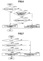
- FIG. 6 is a flow chart showing a high temperature judgment operation in the second clutch protection control of the embodiment 1.
- FIG. 7 is a flow chart showing a vehicle start initiation judgment operation in the second clutch protection control of the embodiment 1.
- FIG. 8 is a drawing showing mode changes of a case where operating points shift on the EV-HEV selection map when a driving force of an EV area or larger is required at an EV start during the CL2 high temperature judgment.
- FIGS. 9A ⁇ 9E are time charts showing each characteristic of accelerator opening, revolution speed (engine revolution or rotation speed, motor revolution or rotation speed), mode change of a comparative example, mode change of an embodiment 1-1 and mode change of an embodiment 1-2, when the driving force of the EV area or larger is required at the EV start during the CL2 high temperature judgment.
- FIG. 10 is a flow chart showing a flow of a second clutch protection control operation executed in the integrated controller 10 of an embodiment 2.
- FIG. 11 is a drawing showing mode changes of a case where operating points that have different rates of change shift on the EV-HEV selection map when the driving force of the EV area or larger is required at the EV start during the CL2 high temperature judgment.
- FIGS. 12A ⁇ 12D are time charts showing each characteristic of accelerator opening of fast rate of change, mode change of [rate of change > C], accelerator opening of slow rate of change and mode change of [rate of change ⁇ C], when the driving force of the EV area or larger is required at the EV start during the CL2 high temperature judgment.
- a control apparatus of a hybrid vehicle of the present invention when a temperature of a second engagement element is a predetermined temperature or higher, by a second engagement element protection control section, since an engine operating (rotating) state is kept regardless of a drive mode, a reserve force of a motor torque, which is saved for an engine start, can be fully used for a driving torque in an first drive mode in which the vehicle travels by only a driving force of a motor.
- a drive area an area condition in which the first drive mode is selected can be extended.
- the frequency of a vehicle start by the first drive mode is increased, while the frequency of a vehicle start that is performed after changing the drive mode to a third drive mode from the engine start is decreased without giving an awkward feeling caused by lack of the driving force to the driver.
- the frequency of the mode change to the third drive mode, which causes the overhearing of the second engagement element, can be reduced at the vehicle start, then the durability and reliability of the second engagement element can be ensured.
- FIG. 1 is a system block diagram showing a rear-wheel-drive FR hybrid vehicle (an example of the hybrid vehicle) employing a control apparatus of an embodiment 1.
- a driveline of the FR hybrid vehicle in the embodiment 1 has an engine Eng, a flywheel FW, a first clutch CL1 (a first engagement element), a motor/generator MG (a motor), a second clutch CL2 (a second engagement element), an automatic transmission AT, a propeller shaft PS, a differential gear DF, a left drive shaft DSL, a right drive shaft DSR, a rear-left wheel (driving wheel) RL, and a rear-right wheel (driving wheel) RR.
- FL is a front-left wheel
- FR is a front-right wheel.
- the engine Eng is a gasoline engine or a diesel engine, and the flywheel FW is provided on an engine output shaft.
- an engine start control, an engine stop control, a valve opening control of a throttle valve and a fuel cut control etc. are carried out.
- the first clutch CL1 is arranged between the engine Eng and the motor/generator MG. Engagement/slip-engagement (half clutch or partial clutch engagement)/disengagement, of the first clutch CL1, are controlled by a first clutch control pressure that is produced by a first clutch hydraulic unit 6 on the basis of a first clutch control command from a first clutch controller 5.
- a normally-closed dry single disc clutch is used as the first clutch CL1 for example.
- the normally-closed dry single disc clutch is urged by a diaphragm spring and its complete engagement is held by this spring force.
- clutch control from the slip-engagement to complete disengagement is carried out by a stroke control using a hydraulic actuator 14 having a piston 14a.
- the motor/generator MG is a synchronous motor/generator in which a permanent magnet is embedded in a rotor and a stator coil is wound around a stator. On the basis of a control command from a motor controller 2, the motor/generator MG is controlled through the application of a three-phase alternating current that is generated by an inverter 3.
- This motor/generator MG works as an electric motor that performs a rotational drive operation by receiving a power from a battery 4 (hereinafter, this state is called a power running state).
- the motor/generator MG works as a generator that generates an electromotive force at both ends of the stator coil, and is able to charge the battery 4 (hereinafter, this operating state is called a regenerative state).
- the rotor of this motor/generator MG is connected to a transmission input shaft of the automatic transmission AT through a damper (not shown).
- the second clutch CL2 is arranged between the motor/generator MG and the rear left and right wheels RL, RR. Engagement/slip-engagement/disengagement, of the second clutch CL2, are controlled by a control pressure that is produced by a second clutch hydraulic unit 8 on the basis of a second clutch control command from an AT controller 7.
- a normally-open wet multiple disc clutch or wet multiple disc brake which is capable of continuously controlling an oil flow amount and the oil pressure through a proportional solenoid, is used.
- the first clutch hydraulic unit 6 and the second clutch hydraulic unit 8 are built into an AT hydraulic control valve unit CVU that is provided in the automatic transmission AT.
- the automatic transmission AT is a multi-range transmission that automatically changes a shift position of multispeed (multistage) of, for example, forward 7 speeds and reverse 1 speed according to a vehicle speed and an accelerator opening and so on.
- An output shaft of the automatic transmission AT is connected to the rear left and right wheels RL, RR through the propeller shaft PS, the differential gear DF, the left drive shaft DSL and the right drive shaft DSR.
- the above second clutch CL2 is not a clutch that is newly added as a special clutch, but an optimum clutch or brake arranged on a torque transmission path of the driveline, among a plurality of frictional engagement elements which are engaged in each speed or each shift stage in the automatic transmission AT, is selected as the second clutch CL2.
- the driveline in the hybrid vehicle in the embodiment 1 has drive modes such as an electric vehicle drive mode (hereinafter called EV drive mode), a hybrid vehicle drive mode (hereinafter called HEV drive mode) and a driving torque control drive mode (hereinafter called WSC drive mode).
- EV drive mode an electric vehicle drive mode
- HEV drive mode a hybrid vehicle drive mode
- WSC drive mode a driving torque control drive mode
- the EV drive mode (a first drive mode) is a mode in which the first clutch CL1 is disengaged and the vehicle travels by only a driving force of the motor/generator MG.
- the HEV drive mode (a second drive mode) is a mode in which the vehicle travels with the first clutch CL1 engaged, and has a motor assist drive mode, a drive electric power generation mode and an engine drive mode.
- the motor assist drive mode is a mode in which the vehicle travels by the driving force of the engine Eng and the motor/generator MG.
- the drive electric power generation mode is a mode in which a part of the driving force of the engine Eng is used for the power generation of the motor/generator MG and the vehicle travels with the remainder of the driving force being the driving force for the drive.
- the engine drive mode is a mode in which the vehicle travels by only the driving force of the engine Eng.
- the WSC drive mode (a third drive mode) is a mode in which the vehicle starts while maintaining the slip-engagement of the second clutch CL2 by a revolution speed control of the motor/generator MG and controlling a clutch torque capacity so that a clutch transmission torque transmitted through the second clutch CL2 is a required driving torque determined in accordance with a vehicle condition and driver's operation.
- This WSC drive mode is selected at the vehicle start in the HEV drive mode in which the engine start and the engagement of the first clutch CL1 are completed before the vehicle start, and at the vehicle start of a case where the mode change to the HEV drive mode is judged when the vehicle starts in the EV drive mode in which the first clutch CL1 is held disengaged.
- the control system of the FR hybrid vehicle has the engine controller 1, the motor controller 2, the inverter 3, the battery 4, the first clutch controller 5, the first clutch hydraulic unit 6, the AT controller 7, the second clutch hydraulic unit 8, a brake controller 9, and an integrated controller 10.
- the engine controller 1, the motor controller 2, the first clutch controller 5, the AT controller 7, the brake controller 9 and the integrated controller 10 are connected with each other through a CAN (Controller Area Network) communication line 11 that allows an information exchange between controllers.
- CAN Controller Area Network
- the engine controller 1 inputs engine rpm information from an engine rpm sensor 12 and a target engine torque command from the integrated controller 10, also inputs the other information. Then the engine controller 1 outputs a command that controls an engine operating point (Ne, Te) to a throttle valve actuator etc. of the engine Eng.
- the motor controller 2 inputs information from a resolver 13 that detects a rotor rotational position of the motor/generator MG, a target MG torque command and a target MG revolution speed command from the integrated controller 10, also inputs the other information. Then the motor controller 2 outputs a command that controls a motor operating point (Nm, Tm) of the motor/generator MG to the inverter 3. In addition, the motor controller 2 measures or checks a battery SOC that indicates a capacity of charge of the battery 4. This battery SOC information is used for the control of the motor/generator MG, and also is sent to the integrated controller 10 through the CAN communication line 11.
- the first clutch controller 5 inputs sensor information from a first clutch stroke sensor 15 that detects a stroke position of the piston 14a of the hydraulic actuator 14 and a target CL1 torque command from the integrated controller 10, also inputs the other information. Then the first clutch controller 5 outputs a command that controls the engagement/slip-engagement/disengagement of the first clutch CL1 to the first clutch hydraulic unit 6 in the AT hydraulic control valve unit CVU.
- the AT controller 7 inputs information from an accelerator opening sensor 16, a vehicle speed sensor 17 and a second clutch temperature sensor 18 (a temperature detection device or means or section) that detects an ambient temperature of a facing of the second clutch CL2. Then, during the travel with a D-range selected, the AT controller 7 searches an optimum speed range (optimum speed stage) according to a position on a shift map, of the operating point determined by an accelerator opening APO and a vehicle speed VSP, and also outputs a control command that achieves the searched speed range to the AT hydraulic control valve unit CVU.
- the shift map is a map where an up-shift line and a down-shift line are drawn according to the accelerator opening and the vehicle speed.
- the AT controller 7 executes a second clutch control in which a command that controls the slip-engagement of the second clutch CL2 is outputted to the second clutch hydraulic unit 8 in the AT hydraulic control valve unit CVU.
- a shift control change command is outputted from the integrated controller 10 instead of a normal shift control, the AT controller 7 executes a shift control based on the shift control change command.
- the brake controller 9 inputs sensor information from a wheel speed sensor 19 for detecting each wheel speed of four wheels and a brake stroke sensor 20 and a regenerative coordination control command from the integrated controller 10, also inputs the other information. Then, for instance, in a case where the brake is applied by only a regenerative braking force upon a brake operation by brake pedal depression, when the braking force is lacking for a required braking force according to a brake stroke BS of the brake pedal depression, the brake controller 9 performs a regenerative coordination brake control so that the shortage of the braking force is compensated by a mechanical braking force (a hydraulic braking force or a motor braking force).
- a mechanical braking force a hydraulic braking force or a motor braking force
- the integrated controller 10 is a controller that controls a consumption energy of the whole vehicle, and in order for the hybrid vehicle to travel at a maximum efficiency, the integrated controller 10 performs the operation.
- the integrated controller 10 inputs information from a motor revolution speed sensor 21 for detecting the motor revolution speed Nm and other sensors/switches 22, also inputs the other information through the CAN communication line 11. Then the integrated controller 10 outputs the target engine torque command to the engine controller 1, outputs the target MG torque command and the target MG revolution speed command to the motor controller 2, outputs the target CL1 torque command to the first clutch controller 5, outputs the target CL2 torque command to the AT controller 7, and outputs the regenerative coordination control command to the brake controller 9.
- Fig. 2 is a control block diagram showing an operation process executed in the integrated controller 10 in the FR hybrid vehicle employing the control apparatus of the embodiment 1.
- Fig. 3 is an EV-HEV selection map used when performing a mode selection operation in the integrated controller 10 in the FR hybrid vehicle employing the control apparatus of the embodiment 1.
- Fig. 4 is a target charge/discharge amount map used when performing a battery charge control in the integrated controller 10 in the FR hybrid vehicle employing the control apparatus of the embodiment 1.
- the integrated controller 10 has a target driving force operating section 100, a mode selecting section 200 (a drive mode change section or means), a target charge/discharge operating section 300, and an operating point commanding section 400.
- the target driving force operating section 100 calculates a target driving force tFo0 on the basis of the accelerator opening APO and the vehicle speed VSP using a target driving force map.
- the mode selecting section 200 selects the EV drive mode or the HEV drive mode as the target drive mode from the accelerator opening APO and the vehicle speed VSP using the EV-HEV selection map (a map) shown in Fig. 3 .
- the target drive mode is set to the HEV drive mode compulsorily or forcibly.
- the WSC drive mode is set in the EV-HEV selection map.
- a HEV ⁇ WSC change line and an EV ⁇ WSC change line are set in a lower vehicle speed area than the first setting vehicle speed VSP1 of an idle rotation speed area of the engine Eng when the automatic transmission AT is set to a first speed.
- a hatch pattern area (oblique line pattern area) is an area where the mode is changed from the HEV drive mode to the WSC drive mode.
- a double hatch pattern area (cross line pattern area) is an area where the mode is changed from WSC drive mode to the EV drive mode.
- the target charge/discharge operating section 300 calculates a target charge/discharge power tP from the battery SOC using a target charge/discharge amount map shown in Fig. 4 .
- the operating point commanding section 400 calculates the target engine torque, the target MG torque, the target MG revolution speed, the target CL1 torque and the target CL2 torque, as an operating point attainment target, on the basis of input information such as the accelerator opening APO, the target driving force tFo0, the target drive mode, the vehicle speed VSP and the target charge/discharge power tP. Then the operating point commanding section 400 outputs the target engine torque command, the target MG torque command and the target MG revolution speed command, the target CL1 torque command, the target CL2 torque command to the controllers 1, 2, 5 and 7 respectively through the CAN communication line 11.
- Fig. 5 is a flow chart showing a flow of a second clutch protection control operation executed in the integrated controller 10 of the embodiment 1 (a second engagement element protection control means or section).
- Fig. 6 is a flow chart showing a high temperature judgment operation in the second clutch protection control of the embodiment 1.
- Fig. 7 is a flow chart showing a vehicle start initiation judgment operation in the second clutch protection control of the embodiment 1.
- step S101 a judgment is made as to whether or not a high temperature judgment of the second clutch CL2 is in progress (whether or not the temperature of the second clutch CL2 is judged to be high). If YES (the CL2 high temperature judgment is in progress), the routine proceeds to step S102. If NO (the CL2 high temperature judgment is finished), the routine proceeds to step S120.
- step S101a if the facing ambient temperature TCL2 of the second clutch CL2 is judged to be higher than a first setting temperature A, the routine proceeds to step S101b, then the temperature of the second clutch CL2 is judged to be high. And, as long as the high temperature judgment is in progress at step S101c and also the facing ambient temperature TCL2 of the second clutch CL2 is judged to be higher than or equal to a second setting temperature B (B ⁇ A) at step S101d, the routine proceeds to step S101b and the temperature of the second clutch CL2 is judged to be high.
- step S101c if it is judged that the high temperature judgment is not in progress at step S101c (i.e. if NO at step S101c), or although it is judged that the high temperature judgment is in progress at step S101c, if the facing ambient temperature TCL2 of the second clutch CL2 is judged to be lower than the second setting temperature B at step S101d, the routine proceeds to step S101e and the high temperature judgment of the second clutch CL2 is finished. That is to say, until the facing ambient temperature TCL2 of the second clutch CL2 becomes lower than the second setting temperature B due to temperature decrease after the facing ambient temperature TCL2 exceeds the first setting temperature A due to temperature increase, it is judged that the high temperature judgment is in progress.
- step S102 in Fig. 5 after judging that the CL2 high temperature judgment is in progress (the temperature of the second clutch CL2 is high) at step S101, a judgment is made as to whether or not the engine Eng is rotating. If YES (the engine Eng is rotating), the routine proceeds to step S108. If NO (the engine Eng is in a halt state), the routine proceeds to step S103.
- step S103 after judging that the engine Eng is in the halt state at step S102, a judgment is made as to whether or not a vehicle start initiation judgment is ON. If YES (the vehicle start initiation judgment is ON), the routine proceeds to step S104. If NO (the vehicle start initiation judgment is OFF), the routine proceeds to RETURN.
- a selected range position is a reverse position (R) or a drive position (D) (at step S103a)
- the accelerator is ON (at step S103b)
- the brake is OFF (at step S103c)
- the routine proceeds to step S103d, and the vehicle start initiation judgment ON is judged.
- the selected range position is the reverse position (R) or the drive position (D) (at step S103a)
- the accelerator is ON (at step S103b)
- the brake is OFF (at step S103c)
- the routine proceeds to step S103e, and the vehicle start initiation judgment OFF is judged.
- step S104 in Fig. 5 subsequent to the judgment of the vehicle start initiation judgment ON at step S103, a judgment is made as to whether or not a current vehicle operating point is present in an EV area on the EV-HEV selection map shown in Fig. 3 . If YES (the operating point is in the EV area), the routine proceeds to step S105. If NO (the operating point is present outside the EV area), the routine proceeds to step S107.
- step S105 after judging that the operating point is present in the EV area at step S104, after the engine Eng is started by slip-engaging the first clutch CL1 and cranking up the engine Eng, the first clutch CL1 is disengaged and an engine stop prohibition flag is set, then the routine proceeds to step S106.
- step S106 subsequent to the CL1 OFF after starting the engine Eng and the engine stop prohibition at step S105, a correction that extends the EV area on the EV-HEV selection map shown in Fig. 3 is made (see Fig. 8 ), and the routine proceeds to RETURN (a map correction section).
- RETURN a map correction section
- step S107 after judging that the operating point is present outside the EV area at step S104, after the engine Eng is started by slip-engaging the first clutch CL1 and cranking up the engine Eng, the first clutch CL1 is engaged and the vehicle starts by the WSC drive mode with the second clutch CL2 slip-engaged, then the routine proceeds to RETURN.
- step S108 after judging that the engine Eng is rotating at step S102, a judgment is made as to whether or not the current vehicle operating point is present in the EV area on the EV-HEV selection map shown in Fig. 3 or the corrected EV-HEV selection map. If YES (the operating point is in the EV area), the routine proceeds to step S113. If NO (the operating point is present outside the EV area), the routine proceeds to step S109.
- step S109 after judging that the operating point is present outside the EV area at step S108, a judgment is made as to whether or not the current vehicle operating point is present in a HEV area on the EV-HEV selection map shown in Fig. 3 or the corrected EV-HEV selection map. If YES (the operating point is present in the HEV area), the routine proceeds to step S110. If NO (the operating point is present outside the HEV area), the routine proceeds to step S111.
- step S110 after judging that the operating point is present in the HEV area at step S109, the drive control in the HEV drive mode is executed, and the routine proceeds to RETURN.
- step S111 after judging that the operating point is present outside the HEV area at step S109, a judgment is made as to whether or not the current vehicle operating point is present in a WSC area on the EV-HEV selection map shown in Fig. 3 or the corrected EV-HEV selection map. If YES (the operating point is present in the WSC area), the routine proceeds to step S112. If NO (the operating point is present outside the WSC area: the vehicle stops), the routine proceeds to step S113.
- step S112 after judging that the operating point is present in the WSC area at step S111, the engine stop prohibition flag is set, and the routine proceeds to RETURN.
- step S113 after judging that the operating point is present in the EV area at step S108, or after judging that the operating point is present outside the WSC area, i.e. the vehicle stops at step S111, the engine stop prohibition flag is set and also the first clutch CL1 is disengaged, then the routine proceeds to step S114.
- the engine stop prohibition flag is already set and also the first clutch CL1 is already disengaged, this state is maintained.
- step S114 subsequent to the engine stop prohibition and the CL1 OFF at step S113, a judgment is made as to whether or not the EV area on the EV-HEV selection map shown in Fig. 3 is extended. If YES (the EV area expansion correction is made), the routine proceeds to step S116. If NO (there is no EV area expansion correction), the routine proceeds to step S115.
- step S115 after judging that there is no EV area expansion correction at step S114, the correction that extends the EV area on the EV-HEV selection map shown in Fig. 3 is made (see Fig. 8 ), and the routine proceeds to step S116 (a map correction section).
- step S116 a map correction section.
- the expansion correction of the EV area on the EV-HEV selection map it is carried out with a size or area which is equivalent to an output of the motor/generator MG for the engine start being a maximum.
- step S116 after judging that the EV area expansion correction is made at step S114, or subsequent to the EV area expansion correction at step S115, a judgment is made as to whether or not a driving force of the EV area or larger (i.e. a driving force that is greater than or equal to a usable driving force in the EV area) on the corrected EV-HEV selection map is required. If YES (there is a demand for the driving force of the EV area or larger), the routine proceeds to step S117. If NO (there is no demand for the driving force of the EV area or larger), the routine proceeds to RETURN.
- a driving force of the EV area or larger i.e. a driving force that is greater than or equal to a usable driving force in the EV area
- step S117 after judging that the demand for the driving force of the EV area or larger rises at step S116, or subsequent to prohibition of change (or prohibition of shift) to the WSC drive mode at step S118, a judgment is made as to whether or not the motor revolution speed is greater (higher) than or equal to the engine revolution speed. If YES (the motor rpm ⁇ the engine rpm), the routine proceeds to step S119. If NO (the motor rpm ⁇ the engine rpm), the routine proceeds to step S118.
- step S118 subsequent to the judgment of the motor rpm ⁇ the engine rpm at step S117, the mode change (or mode shift) from the EV drive mode to the WSC drive mode is prohibited, and the routine returns to step S117 (a third drive mode change prohibition section).
- step S119 subsequent to the judgment of the motor rpm ⁇ the engine rpm at step S117, the first clutch CL1 is engaged at a timing when the motor revolution speed is identical with (or equal to) the engine revolution speed and no clutch relative rotation occurs, and the mode is changed from the EV drive mode to the HEV drive mode directly, then the routine proceeds to RETURN (a second drive mode change section).
- step S120 after judging that the CL2 high temperature judgment is not in progress at step S101, a judgment is made as to whether or not the expansion correction of the EV area on the EV-HEV selection map shown in Fig. 3 is made. If YES (the EV area expansion correction is made), the routine proceeds to step S121. If NO (there is no EV area expansion correction), the routine proceeds to step S122.
- step S121 after judging that the EV area expansion correction is made at step S120, a reduction correction of the extended EV area (the EV area extended by the expansion correction) is performed, and the EV area is returned to the state of the EV area on the EV-HEV selection map shown in Fig. 3 , then the routine proceeds to step S122.
- step S122 after judging that no EV area expansion correction is made at step S120, or subsequent to the process that returns the map to the original state at step S121, the normal mode change control which stops the engine Eng in the EV drive mode in which the first clutch CL1 is disengaged, is executed using the EV-HEV selection map shown in Fig. 3 , then the routine proceeds to RETURN.
- the motor/generator MG In the normal mode change control, since the engine Eng is stopped in the EV drive mode with consideration given to gas mileage performance, the motor/generator MG must save a reserve force of the torque required for the engine start. Because of this, the area of the EV drive mode (the area in which the EV drive mode can be selected) on the EV-HEV selection map ( Fig. 3 ) used in the normal mode change control becomes narrower than an area of the EV drive mode determined by the torque (or driving force) which the primary motor/generator MG is able to output.
- the vehicle start in the case of the vehicle start in the EV drive mode, when the driver's required driving force becomes high by the accelerator pedal depression and then the mode change to the HEV drive mode is judged after the judgment of the vehicle start initiation, the vehicle start is the WSC start from the engine start, and the frequency with which the WSC drive mode is selected is increased.
- the frequency of the slip-control of the second clutch CL2 also increases.
- the WSC start from the engine start occurs often, and the frequency of the slip-control of the second clutch CL2 increases. Then, under a condition in which the second clutch CL2 is too hot, when the slip-control by the WSC start from the engine start is further carried out at the next vehicle start, the facing temperature of the second clutch CL2 increases and becomes high.
- step S103 When the vehicle start initiation judgment ON is judged at step S103 and driver's intention to start the vehicle is confirmed, the routine proceeds from steps S101, S102 and S103 to step S104. Then at step S104, the judgment is made as to whether or not the current vehicle operating point is present in the EV area on the EV-HEV selection map shown in Fig. 3 .
- step S104 when it is judged that the operating point is present outside the EV area upon the vehicle start initiation judgment at a selection start from the state of the accelerator pedal depression, the routine proceeds from step S104 to step S107. And at step S107, after starting the engine Eng, the first clutch CL1 is engaged and the vehicle starts by the WSC drive mode in which the second clutch CL2 is slip-engaged.
- step S101 ⁇ S102 ⁇ S108 ⁇ S109 ⁇ S111 ⁇ S112 are executed. Then at step S112, the stop of the engine Eng is prohibited. Subsequently, when the operating point shifts to the HEV area, in the flow chart in Fig. 5 , the control steps S101 ⁇ S102 ⁇ S108 ⁇ S109 ⁇ S110 are executed. Then at step S110, the drive control in the HEV drive mode is executed.
- the mode change control in which the mode is changed from the WSC drive mode to the HEV drive mode at the vehicle start is carried out.
- step S104 the flow proceeds from step S104 to steps S105 and S106.
- step S105 after starting the engine Eng by slip-engaging the first clutch CL1 and cranking up the engine Eng, the first clutch CL1 is disengaged and the engine stop prohibition flag is set.
- step S106 the correction that extends the EV area on the EV-HEV selection map shown in Fig. 3 is made.
- the control steps S101 ⁇ S102 ⁇ S108 ⁇ S113 ⁇ S114 ⁇ S116 are executed. Then when there is no demand for the driving force of the extended EV area (the EV area extended by the expansion correction) or larger at step S116, the flow of steps S101 ⁇ S102 ⁇ S108 ⁇ S113 ⁇ S114 ⁇ S116 is repeated. Then, until it is judged that the operating point is not present in the EV area on the correction map at step S108, the engine Eng rotates in an idle rotation speed range, and the EV drive mode in which the first clutch CL1 is disengaged is maintained.
- step S118 the mode change from the EV drive mode to the WSC drive mode is prohibited.
- the second clutch protection control executed when it is judged that the temperature of the second clutch CL2 is high (when it is judged that the temperature of the second clutch CL2 is a predetermined temperature or higher), features the following points.
- Engine stop prohibition judgment logic of the embodiment 1 is logic that does not stop the engine Eng when the facing ambient temperature of the second clutch CL2 is high. More specifically,
- the reserve force of the motor torque can be fully used for the driving torque in the EV drive mode in which the vehicle travels by only the driving force of the motor/generator MG.
- the drive area an area condition in which the EV drive mode is selected can be extended.
- the frequency of the mode change from the EV drive mode to the WSC drive mode can be reduced without giving an awkward feeling caused by lack of the driving force to the driver.
- EV feasible area judgment logic of the embodiment 1 is logic which judges necessity for the engine start reserve force depending on whether the engine Eng is operating (rotating) in the EV drive mode selection state and performs the correction that extends the EV area on the predetermined EV-HEV selection map (steps S106, S115). That is, as shown in Fig. 8 , an EV ⁇ HEV change line on the EV-HEV selection map before the correction determines or defines the EV drive mode area according to the battery SOC and the motor revolution speed (output characteristic) etc.. On the other hand, an EV ⁇ HEV change line on the EV-HEV selection map after the correction extends the EV drive mode area toward the HEV drive mode area with a size or area which is equivalent to the engine start reserve force being a maximum.
- the mode change control using the EV-HEV selection map before the correction i.e. using non-corrected EV-HEV selection map
- the mode change control using the EV-HEV selection map after the correction i.e. using the corrected EV-HEV selection map
- the vehicle start is the EV start, and subsequently, the mode shifts from the EV drive mode to the HEV drive mode.
- Control logic that maintains the EV drive mode at the accelerator depression start of the embodiment 1 is logic that maintains the EV drive mode in a certain range or area when the accelerator pedal is depressed at the EV start, even if the driver's required driving force cannot be attained.
- step S116 even if the mode change from the EV drive mode to the WSC drive mode on the corrected EV-HEV selection map is judged at the vehicle start from the vehicle halt state (YES at step S116), the mode change from the EV drive mode to the WSC drive mode is prohibited until the motor revolution speed is greater (higher) than or equal to the engine revolution speed (step S117 ⁇ step S118). Then when the motor revolution speed is greater than or equal to the engine revolution speed, the first clutch CL1 is engaged and the mode is changed to the HEV drive mode (step S117 ⁇ step S119).
- the mode change control using the EV-HEV selection map before the correction i.e. using non-corrected EV-HEV selection map
- the mode change control using the EV-HEV selection map after the correction i.e. using the corrected EV-HEV selection map
- the control logic maintaining the EV drive mode is an embodiment 1-2.
- the vehicle start is the WSC start.
- the heat protection of the second clutch CL2 is further achieved.
- a mode change shock is suppressed, and the mode change from the EV drive mode to the HEV drive mode, which skips the WSC drive mode, can be achieved.
- control apparatus of the FR hybrid vehicle in the embodiment 1 provides the following effects.
- the control apparatus of the hybrid vehicle the hybrid vehicle having the engine (Eng), the motor (motor/generator MG), the first engagement element (first clutch CL1) arranged between the engine (Eng) and the motor (MG) for connecting/disconnecting the engine (Eng) and the motor (MG) and the second engagement element (second clutch CL2) arranged between the motor (MG) and driving wheels (RL, RR) for connecting/disconnecting the motor (MG) and the driving wheels (RL, RR),
- the control apparatus comprises: the drive mode change section (mode selecting section 200) that changes the following drive modes according to the vehicle travel state: the first drive mode (EV drive mode) in which the first engagement element (CL1) is disengaged and the second engagement element (CL2) is engaged then the vehicle travels by only the driving force of the motor (MG), the second drive mode (HEV drive mode) in which the first and second engagement elements (CL1, CL2) are respectively engaged then the vehicle travels by both driving forces of the engine (Eng) and the motor (MG), and the third drive mode (WS
- the frequency of the mode change to the third drive mode (the WSC drive mode), which causes the overhearing of the second engagement element (the second clutch CL2), can be reduced at the vehicle start, then the durability and reliability of the second engagement element can be ensured.
- the second engagement element protection control section ( Fig. 5 ) extends an area condition in which the first drive mode (EV drive mode) is selected as compared with no execution of the protection control. With this expansion, the frequency of the shift to the third drive mode (the WSC drive mode) in which the temperature of the second engagement element (the second clutch CL2) could become too high can be reduced.
- the drive mode change section (mode selecting section 200) has the map (EV-HEV selection map) by which the drive mode is determined on the basis of at least the accelerator opening (APO), and the second engagement element protection control section ( Fig. 5 ) has the map correction section (steps S106, S115) which makes the correction that extends the area of the first drive mode (EV drive mode) on the map (EV-HEV selection map), with the area which is equivalent to the output of the motor (MG) required for the engine start being the maximum, upon the execution of the protection control keeping the engine rotating state.
- map EV-HEV selection map
- the second engagement element protection control section ( Fig. 5 ) further has the third drive mode change prohibition section (steps S117 ⁇ S118) that prohibits the mode change to the third drive mode (WSC drive mode) until the motor revolution speed is greater than or equal to the engine revolution speed, even if the mode change from the first drive mode (EV drive mode) to the third drive mode (WSC drive mode) on the corrected map (EV-HEV selection map) is judged at the vehicle start from the vehicle halt state; and the second drive mode change section (steps S117 ⁇ S119) that changes the drive mode to the second drive mode (HEV drive mode) with the first engagement element (CL1) engaged when the motor revolution speed is greater than or equal to the engine revolution speed.
- the third drive mode change prohibition section steps S117 ⁇ S118) that prohibits the mode change to the third drive mode (WSC drive mode) until the motor revolution speed is greater than or equal to the engine revolution speed, even if the mode change from the first drive mode (EV drive mode) to the third drive mode (WSC drive mode)
- the heat protection of the second engagement element (the second clutch CL2) is further achieved.
- the mode change from the first drive mode (the EV drive mode) to the second drive mode (the HEV drive mode) can be achieved while suppressing the mode change shock.
- An embodiment 2 is the one that employs control logic that maintains the EV drive mode in a case where a rate of change (or speed of change) of the required driving force is low (slow) at the accelerator depression start.
- Fig. 10 is a flow chart showing a flow of a second clutch protection control operation executed in the integrated controller 10 of the embodiment 2 (a second engagement element protection control means).
- step S217 in Fig. 10 after judging that the demand for the driving force of the EV area or larger rises at step S216, or subsequent to the maintenance of the EV drive mode at step S218, a judgment is made as to whether or not a rate of change (or speed of change) of the required driving force (e.g. the accelerator opening APO, the target driving force etc.) exceeds a setting change rate (or change speed) C. If YES (the change rate of the required driving force > C), the routine proceeds to step S219. If NO (the change rate of the required driving force ⁇ C), the routine proceeds to step S218.
- a rate of change (or speed of change) of the required driving force e.g. the accelerator opening APO, the target driving force etc.
- step S2128 subsequent to the judgment of the change rate of the required driving force ⁇ C at step S217, the EV drive mode is maintained as it is, regardless of the demand for the driving force of the EV area or larger, and the routine proceeds to step S223 (a first drive mode maintenance section).
- step S223 subsequent to the maintenance of the EV drive mode at step S218, a judgment is made as to whether or not the operating point is present in the HEV area on the extended map. If YES (the operating point is in the HEV area), the routine proceeds to step S224. If NO, the routine returns to step S217.
- step S224 after judging that the operating point is present in the HEV area on the extended map at step S223, the first clutch CL1 is engaged and the mode is changed to the HEV drive mode, then the routine proceeds to RETURN.
- step S219 subsequent to the judgment of the change rate of the required driving force > C at step S217, the mode is changed to the WSC drive mode in which the second clutch CL2 is slip-engaged and the revolution speed control of the motor/generator MG is performed then the first clutch CL1 is engaged at the timing when the motor revolution speed is identical with the engine revolution speed and no clutch relative rotation occurs, then the routine proceeds to RETURN.
- System and operation process etc. of the embodiment 2 are the same as those shown in Figs. 1 ⁇ 4 , 6 and 7 , of the embodiment 1. Thus, these drawings and explanations are omitted here.
- Control logic that maintains the EV drive mode at the accelerator depression start of the embodiment 2 is logic that maintains the EV drive mode in a certain range or area when the accelerator pedal is depressed at the EV start, even if the driver's required driving force cannot be attained.
- the mode change from the EV drive mode to the WSC drive mode on the corrected EV-HEV selection map is judged at the vehicle start from the vehicle halt state (YES at step S216), in the case where the change rate of the required driving force exceeds the setting change rate C, namely in the case where the required driving force is great, the mode change from the EV drive mode to the WSC drive mode is carried out in accordance with the normal mode change manner (steps S217 ⁇ S219).
- the EV drive mode is maintained as it is, regardless of the demand for the driving force of the EV area or larger (steps S217 ⁇ S218).
- Fig. 11 a case where the vehicle operating point changes from the operating point E to an operating point H at the EV start, will be explained.
- an accelerator opening characteristic of a fast rate of change in Fig. 12A in the case where the change rate of the required driving force exceeds the setting change rate C, as can be seen in a mode change characteristic of the change rate > C in Fig. 12B , the mode change of the EV drive mode ⁇ the WSC drive mode ⁇ the HEV drive mode is carried out.
- the heat protection of the second clutch CL2 is further achieved. That is to say, when the change rate of the required driving force is the setting change rate C or less, the driver's demand for the driving force is estimated to be low. Thus, even if the EV drive mode is maintained, the awkward feeling given to the driver can be minimized, and it is possible to prohibit the mode change to the WSC drive mode, which is effective in the heat protection of the second clutch CL2.
- Other operations of the embodiment 2 are the same as the embodiment 1, thus their explanations are omitted here.
- the control apparatus of the FR hybrid vehicle in the embodiment 2 provides the following effect, in addition to the effects (1) ⁇ (4) of the embodiment 1.
- the second engagement element protection control section ( Fig. 10 ) further has the first drive mode maintenance section (step S218) that maintains the first drive mode (EV drive mode) as it is, when the rate of change of the required driving force is less than or equal to the setting change rate (C) (NO at step S217), even if the mode change from the first drive mode (EV drive mode) to the third drive mode (WSC drive mode) on the corrected map (EV-HEV selection map) is judged (YES at step S216) at the vehicle start from the vehicle halt state.
- the first drive mode maintenance section step S2128 that maintains the first drive mode (EV drive mode) as it is, when the rate of change of the required driving force is less than or equal to the setting change rate (C) (NO at step S217), even if the mode change from the first drive mode (EV drive mode) to the third drive mode (WSC drive mode) on the corrected map (EV-HEV selection map) is judged (YES at step S216) at the vehicle start from the vehicle halt state
- the change rate of the required driving force is the predetermined value (the setting change rate C) or less
- the further heat protection of the second clutch CL2 can be achieved while minimizing the awkward feeling given to the driver.
- control apparatus of the hybrid vehicle according to the present invention has been explained on the basis of the embodiments 1 and 2, the present invention is not limited to the embodiments 1 and 2.
- the second clutch temperature sensor 18 that is a thermometer for directly measuring the ambient temperature of the facing of the second clutch CL2, until the facing ambient temperature TCL2 of the second clutch CL2 becomes lower than the second setting temperature B due to temperature decrease after the facing ambient temperature TCL2 exceeds the first setting temperature A due to temperature increase, it is judged that the high temperature judgment is in progress.
- the second clutch temperature sensor 18 it could be possible to use a second clutch temperature estimation means which measures or checks heat value of the second clutch CL2 (that is estimated from the transmission torque and slip-revolution speed difference etc.) and heat release of the second clutch CL2 (that is estimated from engagement time, disengagement time and an atmospheric temperature etc.) then estimates the facing ambient temperature of the second clutch CL2.
- control which prohibits the mode change to the WSC drive mode and maintains the EV drive mode at the accelerator depression start then changes the mode from the EV drive mode to the HEV drive mode is explained.
- the control logic that maintains the EV drive mode in the case where the change rate of the required driving force is low (slow) at the accelerator depression start is employed.
- each control logic of the embodiments 1 and 2 which maintains the EV drive mode could be combined as a parallel control logic.
- control logic that maintains the EV drive mode, which is executed under other conditions might be employed.
- control apparatus is applied for the FR hybrid vehicle.
- control apparatus can also be applied for the FF hybrid vehicle. That is, as long as the hybrid vehicle has the engine, the first engagement element, the motor, the second engagement element and the driving wheels on the driveline from an upstream side, the control apparatus can be applied for such vehicle.
Abstract
Description
- The present invention relates to a control apparatus for a hybrid vehicle which has a plurality of drive modes and changes the drive mode according to predetermined conditions.
- In recent years, there have been proposed and developed various control apparatuses for the hybrid vehicle in which a first engagement element to connect/disconnect an engine and a motor and a second engagement element to connect/disconnect the motor and driving wheels are provided. The hybrid vehicle has, as drive modes, a motor-use drive mode (hereinafter called "EV drive mode") in which the vehicle travels with only the motor being a power source and an engine-use drive mode (hereinafter called "HEV drive mode") in which the vehicle travels with the engine included as the power source. In such control apparatuses, for example, Japanese Patent Provisional Publication No.
2005-221073 JP2005-221073 - In such hybrid vehicles, since there is no element such as a torque converter which serves to absorb input rotation speed and change of the rotation speed, when the vehicle starts with the first and second engagement elements completely engaged, a vehicle speed is determined according to an engine rotation speed. On the other hand, regarding the engine, there is a lower limit value of an idle rotation speed for maintaining a self-rotation of the engine. Under a condition in which an idle-up control by engine warming-up etc. is being carried out, this lower limit value of the idle rotation speed becomes even higher.
- Therefore, at the vehicle start when a required driving force by a driver is high and the vehicle start using the both driving forces of the engine and the motor is required, in order to fulfill a rotation absorption function while meeting the required driving force, by performing a slip-control of the second engagement element, the vehicle travel using the engine becomes possible. This drive mode is called "WSC (Wet Start Clutch) drive mode".
- In the related art control apparatus of the hybrid vehicle, however, normally, the engine is stopped upon the vehicle travel in the EV drive mode. Thus, when the driver's required driving force becomes high by a driver's accelerator pedal depressing operation and a mode change to the HEV drive mode is judged (or determined), because a reserve force (or a reserve torque) must be saved for an engine start, the motor can use only torque except the reserve torque in the EV drive mode. That is, when the driving force that is greater than or equal to a usable driving force in the EV drive mode is required, after starting the engine by the reserve force of the motor, the mode is changed to the HEV drive mode, then it becomes possible to meet the required driving force by both an engine torque and the motor torque. Hence, an area that can maintain the EV drive mode narrows by a magnitude of the reserve force for the engine start.
- As explained above, since the reserve force of the torque required for the engine start is needed to be saved, the area of the EV drive mode (the area in which the EV drive mode can be selected) becomes narrower than an area of the EV drive mode determined by the torque which the primary motor is able to output. For this reason, upon the vehicle start, the number of occurrences of a WSC start from the engine start is increased, and the frequency of the slip-control of the second engagement element is also increased with this occurrence.
- In particular, at the accelerator pedal depression start where the driver's required driving force is high, the vehicle start is the WSC start from the engine start, and the frequency of the slip-control of the second engagement element increases. Then, under a condition in which the second engagement element is too hot by the slip-control, when the slip-control by the WSC drive mode is further carried out at the next vehicle start, there is a possibility that durability of the second engagement element will decrease.
- For this problem, it is therefore an object of the present invention to provide a control apparatus for the hybrid vehicle, which can ensure the durability and reliability of the second engagement element by reducing the frequency of the mode change to a third drive mode (the WSC drive mode) that leads to the overheating (heat generation) of the second engagement element upon the vehicle start.
- According to one aspect of the present invention, a control apparatus of a hybrid vehicle, the hybrid vehicle has an engine, a motor, a first engagement element arranged between the engine and the motor for connecting/disconnecting the engine and the motor and a second engagement element arranged between the motor and driving wheels for connecting/disconnecting the motor and the driving wheels, the control apparatus comprises: a drive mode change section that changes the following drive modes according to a vehicle travel state: a first drive mode in which the first engagement element is disengaged and the second engagement element is engaged then the vehicle travels by only a driving force of the motor, a second drive mode in which the first and second engagement elements are respectively engaged then the vehicle travels by both driving forces of the engine and the motor, and a third drive mode in which the second engagement element is slip-engaged then the vehicle travels by a driving force transmitted through the second engagement element; a temperature detection section that detects a temperature of the second engagement element; and a second engagement element protection control section that keeps an engine rotating state regardless of the drive mode when the temperature of the second engagement element is a predetermined temperature or higher.
- According to another aspect of the invention, a method for controlling a hybrid vehicle, the hybrid vehicle which is provided with a first engagement element arranged between an engine and a motor for connecting/disconnecting the engine and the motor and a second engagement element arranged between the motor and driving wheels for connecting/disconnecting the motor and the driving wheels, and has the following drive modes: a first drive mode in which the first engagement element is disengaged and the second engagement element is engaged then the vehicle travels by only a driving force of the motor, a second drive mode in which the first and second engagement elements are respectively engaged then the vehicle travels by both driving forces of the engine and the motor, and a third drive mode in which the second engagement element is slip-engaged then the vehicle travels by a driving force transmitted through the second engagement element, the method comprises: changing the drive mode according to a vehicle travel state; detecting a temperature of the second engagement element, and keeping an engine rotating state regardless of the drive mode when the temperature of the second engagement element is a predetermined temperature or higher.
- The other objects and features of this invention will become understood from the following description with reference to the accompanying drawings.
-
FIG. 1 is a system block diagram showing a rear-wheel-drive FR hybrid vehicle (an example of the hybrid vehicle) employing a control apparatus of anembodiment 1. -
FIG. 2 is a control block diagram showing an operation process executed in an integratedcontroller 10 in the FR hybrid vehicle employing the control apparatus of theembodiment 1. -
FIG. 3 is an EV-HEV selection map used when performing a mode selection operation in the integratedcontroller 10 in the FR hybrid vehicle employing the control apparatus of theembodiment 1. -
FIG. 4 is a target charge/discharge amount map used when performing a battery charge control in the integratedcontroller 10 in the FR hybrid vehicle employing the control apparatus of theembodiment 1. -
FIG. 5 is a flow chart showing a flow of a second clutch protection control operation executed in the integratedcontroller 10 of theembodiment 1. -
FIG. 6 is a flow chart showing a high temperature judgment operation in the second clutch protection control of theembodiment 1. -
FIG. 7 is a flow chart showing a vehicle start initiation judgment operation in the second clutch protection control of theembodiment 1. -
FIG. 8 is a drawing showing mode changes of a case where operating points shift on the EV-HEV selection map when a driving force of an EV area or larger is required at an EV start during the CL2 high temperature judgment. -
FIGS. 9A ∼ 9E are time charts showing each characteristic of accelerator opening, revolution speed (engine revolution or rotation speed, motor revolution or rotation speed), mode change of a comparative example, mode change of an embodiment 1-1 and mode change of an embodiment 1-2, when the driving force of the EV area or larger is required at the EV start during the CL2 high temperature judgment. -
FIG. 10 is a flow chart showing a flow of a second clutch protection control operation executed in the integratedcontroller 10 of an embodiment 2. -
FIG. 11 is a drawing showing mode changes of a case where operating points that have different rates of change shift on the EV-HEV selection map when the driving force of the EV area or larger is required at the EV start during the CL2 high temperature judgment. -
FIGS. 12A ∼ 12D are time charts showing each characteristic of accelerator opening of fast rate of change, mode change of [rate of change > C], accelerator opening of slow rate of change and mode change of [rate of change ≦ C], when the driving force of the EV area or larger is required at the EV start during the CL2 high temperature judgment. - According to a control apparatus of a hybrid vehicle of the present invention, when a temperature of a second engagement element is a predetermined temperature or higher, by a second engagement element protection control section, since an engine operating (rotating) state is kept regardless of a drive mode, a reserve force of a motor torque, which is saved for an engine start, can be fully used for a driving torque in an first drive mode in which the vehicle travels by only a driving force of a motor.
- In other words, while meeting driver's required driving force, a drive area (an area condition) in which the first drive mode is selected can be extended. With this expansion of the first drive mode selection area, the frequency of a vehicle start by the first drive mode is increased, while the frequency of a vehicle start that is performed after changing the drive mode to a third drive mode from the engine start is decreased without giving an awkward feeling caused by lack of the driving force to the driver.
- As a result, the frequency of the mode change to the third drive mode, which causes the overhearing of the second engagement element, can be reduced at the vehicle start, then the durability and reliability of the second engagement element can be ensured.
- Embodiments of the present invention will now be explained below with reference to the drawings.
- First, the whole system of the present invention will be explained.
Fig. 1 is a system block diagram showing a rear-wheel-drive FR hybrid vehicle (an example of the hybrid vehicle) employing a control apparatus of anembodiment 1. - As can be seen in
Fig. 1 , a driveline of the FR hybrid vehicle in theembodiment 1 has an engine Eng, a flywheel FW, a first clutch CL1 (a first engagement element), a motor/generator MG (a motor), a second clutch CL2 (a second engagement element), an automatic transmission AT, a propeller shaft PS, a differential gear DF, a left drive shaft DSL, a right drive shaft DSR, a rear-left wheel (driving wheel) RL, and a rear-right wheel (driving wheel) RR. FL is a front-left wheel, FR is a front-right wheel. - The engine Eng is a gasoline engine or a diesel engine, and the flywheel FW is provided on an engine output shaft. On the basis of an engine control command from an
engine controller 1, an engine start control, an engine stop control, a valve opening control of a throttle valve and a fuel cut control etc. are carried out. - The first clutch CL1 is arranged between the engine Eng and the motor/generator MG. Engagement/slip-engagement (half clutch or partial clutch engagement)/disengagement, of the first clutch CL1, are controlled by a first clutch control pressure that is produced by a first clutch
hydraulic unit 6 on the basis of a first clutch control command from afirst clutch controller 5. As the first clutch CL1, for example, a normally-closed dry single disc clutch is used. The normally-closed dry single disc clutch is urged by a diaphragm spring and its complete engagement is held by this spring force. Further, clutch control from the slip-engagement to complete disengagement is carried out by a stroke control using ahydraulic actuator 14 having apiston 14a. - The motor/generator MG is a synchronous motor/generator in which a permanent magnet is embedded in a rotor and a stator coil is wound around a stator. On the basis of a control command from a motor controller 2, the motor/generator MG is controlled through the application of a three-phase alternating current that is generated by an
inverter 3. This motor/generator MG works as an electric motor that performs a rotational drive operation by receiving a power from a battery 4 (hereinafter, this state is called a power running state). And also, in a case where the rotor is rotated by receiving a rotational energy from the engine Eng or the driving wheels, the motor/generator MG works as a generator that generates an electromotive force at both ends of the stator coil, and is able to charge the battery 4 (hereinafter, this operating state is called a regenerative state). The rotor of this motor/generator MG is connected to a transmission input shaft of the automatic transmission AT through a damper (not shown). - The second clutch CL2 is arranged between the motor/generator MG and the rear left and right wheels RL, RR. Engagement/slip-engagement/disengagement, of the second clutch CL2, are controlled by a control pressure that is produced by a second clutch
hydraulic unit 8 on the basis of a second clutch control command from anAT controller 7. As the second clutch CL2, for example, a normally-open wet multiple disc clutch or wet multiple disc brake, which is capable of continuously controlling an oil flow amount and the oil pressure through a proportional solenoid, is used. Here, the first clutchhydraulic unit 6 and the second clutchhydraulic unit 8 are built into an AT hydraulic control valve unit CVU that is provided in the automatic transmission AT. - The automatic transmission AT is a multi-range transmission that automatically changes a shift position of multispeed (multistage) of, for example, forward 7 speeds and reverse 1 speed according to a vehicle speed and an accelerator opening and so on. An output shaft of the automatic transmission AT is connected to the rear left and right wheels RL, RR through the propeller shaft PS, the differential gear DF, the left drive shaft DSL and the right drive shaft DSR. Here, the above second clutch CL2 is not a clutch that is newly added as a special clutch, but an optimum clutch or brake arranged on a torque transmission path of the driveline, among a plurality of frictional engagement elements which are engaged in each speed or each shift stage in the automatic transmission AT, is selected as the second clutch CL2.
- The driveline in the hybrid vehicle in the
embodiment 1 has drive modes such as an electric vehicle drive mode (hereinafter called EV drive mode), a hybrid vehicle drive mode (hereinafter called HEV drive mode) and a driving torque control drive mode (hereinafter called WSC drive mode). - The EV drive mode (a first drive mode) is a mode in which the first clutch CL1 is disengaged and the vehicle travels by only a driving force of the motor/generator MG.
- The HEV drive mode (a second drive mode) is a mode in which the vehicle travels with the first clutch CL1 engaged, and has a motor assist drive mode, a drive electric power generation mode and an engine drive mode. The motor assist drive mode is a mode in which the vehicle travels by the driving force of the engine Eng and the motor/generator MG. The drive electric power generation mode is a mode in which a part of the driving force of the engine Eng is used for the power generation of the motor/generator MG and the vehicle travels with the remainder of the driving force being the driving force for the drive. The engine drive mode is a mode in which the vehicle travels by only the driving force of the engine Eng.
- The WSC drive mode (a third drive mode) is a mode in which the vehicle starts while maintaining the slip-engagement of the second clutch CL2 by a revolution speed control of the motor/generator MG and controlling a clutch torque capacity so that a clutch transmission torque transmitted through the second clutch CL2 is a required driving torque determined in accordance with a vehicle condition and driver's operation. This WSC drive mode is selected at the vehicle start in the HEV drive mode in which the engine start and the engagement of the first clutch CL1 are completed before the vehicle start, and at the vehicle start of a case where the mode change to the HEV drive mode is judged when the vehicle starts in the EV drive mode in which the first clutch CL1 is held disengaged.
- Next, a control system of the hybrid vehicle will be explained.
As shown inFig. 1 , the control system of the FR hybrid vehicle has theengine controller 1, the motor controller 2, theinverter 3, thebattery 4, the firstclutch controller 5, the first clutchhydraulic unit 6, theAT controller 7, the second clutchhydraulic unit 8, abrake controller 9, and anintegrated controller 10. Here, theengine controller 1, the motor controller 2, the firstclutch controller 5, theAT controller 7, thebrake controller 9 and theintegrated controller 10 are connected with each other through a CAN (Controller Area Network)communication line 11 that allows an information exchange between controllers. - The
engine controller 1 inputs engine rpm information from anengine rpm sensor 12 and a target engine torque command from the integratedcontroller 10, also inputs the other information. Then theengine controller 1 outputs a command that controls an engine operating point (Ne, Te) to a throttle valve actuator etc. of the engine Eng. - The motor controller 2 inputs information from a
resolver 13 that detects a rotor rotational position of the motor/generator MG, a target MG torque command and a target MG revolution speed command from the integratedcontroller 10, also inputs the other information. Then the motor controller 2 outputs a command that controls a motor operating point (Nm, Tm) of the motor/generator MG to theinverter 3. In addition, the motor controller 2 measures or checks a battery SOC that indicates a capacity of charge of thebattery 4. This battery SOC information is used for the control of the motor/generator MG, and also is sent to theintegrated controller 10 through theCAN communication line 11. - The first
clutch controller 5 inputs sensor information from a firstclutch stroke sensor 15 that detects a stroke position of thepiston 14a of thehydraulic actuator 14 and a target CL1 torque command from the integratedcontroller 10, also inputs the other information. Then the firstclutch controller 5 outputs a command that controls the engagement/slip-engagement/disengagement of the first clutch CL1 to the first clutchhydraulic unit 6 in the AT hydraulic control valve unit CVU. - The
AT controller 7 inputs information from anaccelerator opening sensor 16, avehicle speed sensor 17 and a second clutch temperature sensor 18 (a temperature detection device or means or section) that detects an ambient temperature of a facing of the second clutch CL2. Then, during the travel with a D-range selected, theAT controller 7 searches an optimum speed range (optimum speed stage) according to a position on a shift map, of the operating point determined by an accelerator opening APO and a vehicle speed VSP, and also outputs a control command that achieves the searched speed range to the AT hydraulic control valve unit CVU. Here, the shift map is a map where an up-shift line and a down-shift line are drawn according to the accelerator opening and the vehicle speed. - In addition to the automatic transmission control, when inputting a target CL2 torque command from the integrated
controller 10, theAT controller 7 executes a second clutch control in which a command that controls the slip-engagement of the second clutch CL2 is outputted to the second clutchhydraulic unit 8 in the AT hydraulic control valve unit CVU. Moreover, when a shift control change command is outputted from the integratedcontroller 10, instead of a normal shift control, theAT controller 7 executes a shift control based on the shift control change command. - The
brake controller 9 inputs sensor information from awheel speed sensor 19 for detecting each wheel speed of four wheels and abrake stroke sensor 20 and a regenerative coordination control command from the integratedcontroller 10, also inputs the other information. Then, for instance, in a case where the brake is applied by only a regenerative braking force upon a brake operation by brake pedal depression, when the braking force is lacking for a required braking force according to a brake stroke BS of the brake pedal depression, thebrake controller 9 performs a regenerative coordination brake control so that the shortage of the braking force is compensated by a mechanical braking force (a hydraulic braking force or a motor braking force). - The
integrated controller 10 is a controller that controls a consumption energy of the whole vehicle, and in order for the hybrid vehicle to travel at a maximum efficiency, theintegrated controller 10 performs the operation. Theintegrated controller 10 inputs information from a motorrevolution speed sensor 21 for detecting the motor revolution speed Nm and other sensors/switches 22, also inputs the other information through theCAN communication line 11. Then theintegrated controller 10 outputs the target engine torque command to theengine controller 1, outputs the target MG torque command and the target MG revolution speed command to the motor controller 2, outputs the target CL1 torque command to the firstclutch controller 5, outputs the target CL2 torque command to theAT controller 7, and outputs the regenerative coordination control command to thebrake controller 9. -
Fig. 2 is a control block diagram showing an operation process executed in theintegrated controller 10 in the FR hybrid vehicle employing the control apparatus of theembodiment 1.Fig. 3 is an EV-HEV selection map used when performing a mode selection operation in theintegrated controller 10 in the FR hybrid vehicle employing the control apparatus of theembodiment 1.Fig. 4 is a target charge/discharge amount map used when performing a battery charge control in theintegrated controller 10 in the FR hybrid vehicle employing the control apparatus of theembodiment 1. - In the following, the operation process executed in the
integrated controller 10 will be explained with reference toFigs. 2 to 4 . - As shown in
Fig. 2 , theintegrated controller 10 has a target drivingforce operating section 100, a mode selecting section 200 (a drive mode change section or means), a target charge/discharge operating section 300, and an operating pointcommanding section 400. - The target driving
force operating section 100 calculates a target driving force tFo0 on the basis of the accelerator opening APO and the vehicle speed VSP using a target driving force map. - The
mode selecting section 200 selects the EV drive mode or the HEV drive mode as the target drive mode from the accelerator opening APO and the vehicle speed VSP using the EV-HEV selection map (a map) shown inFig. 3 . However, if the battery SOC is lower than or equal to a predetermined value, the target drive mode is set to the HEV drive mode compulsorily or forcibly. As seen in the EV-HEV selection map, in order to output a great driving force when the vehicle speed VSP is in a low vehicle speed area of a first setting vehicle speed VSP1 or less and the accelerator opening APO is large, the WSC drive mode is set in the EV-HEV selection map. A HEV → WSC change line and an EV → WSC change line are set in a lower vehicle speed area than the first setting vehicle speed VSP1 of an idle rotation speed area of the engine Eng when the automatic transmission AT is set to a first speed. In the EV-HEV selection map, a hatch pattern area (oblique line pattern area) is an area where the mode is changed from the HEV drive mode to the WSC drive mode. A double hatch pattern area (cross line pattern area) is an area where the mode is changed from WSC drive mode to the EV drive mode. - The target charge/
discharge operating section 300 calculates a target charge/discharge power tP from the battery SOC using a target charge/discharge amount map shown inFig. 4 . - The operating point
commanding section 400 calculates the target engine torque, the target MG torque, the target MG revolution speed, the target CL1 torque and the target CL2 torque, as an operating point attainment target, on the basis of input information such as the accelerator opening APO, the target driving force tFo0, the target drive mode, the vehicle speed VSP and the target charge/discharge power tP. Then the operating pointcommanding section 400 outputs the target engine torque command, the target MG torque command and the target MG revolution speed command, the target CL1 torque command, the target CL2 torque command to thecontrollers CAN communication line 11. -
Fig. 5 is a flow chart showing a flow of a second clutch protection control operation executed in theintegrated controller 10 of the embodiment 1 (a second engagement element protection control means or section).Fig. 6 is a flow chart showing a high temperature judgment operation in the second clutch protection control of theembodiment 1.Fig. 7 is a flow chart showing a vehicle start initiation judgment operation in the second clutch protection control of theembodiment 1. - In the following, each step in the flow charts shown in
Figs. 5 to 7 will be explained. - In
Fig. 5 , at step S101, a judgment is made as to whether or not a high temperature judgment of the second clutch CL2 is in progress (whether or not the temperature of the second clutch CL2 is judged to be high). If YES (the CL2 high temperature judgment is in progress), the routine proceeds to step S102. If NO (the CL2 high temperature judgment is finished), the routine proceeds to step S120. - Here, with regard to the high temperature judgment of the second clutch CL2, it is made by the flow chart shown in
Fig. 6 . At step S101a, if the facing ambient temperature TCL2 of the second clutch CL2 is judged to be higher than a first setting temperature A, the routine proceeds to step S101b, then the temperature of the second clutch CL2 is judged to be high. And, as long as the high temperature judgment is in progress at step S101c and also the facing ambient temperature TCL2 of the second clutch CL2 is judged to be higher than or equal to a second setting temperature B (B < A) at step S101d, the routine proceeds to step S101b and the temperature of the second clutch CL2 is judged to be high. On the other hand, if it is judged that the high temperature judgment is not in progress at step S101c (i.e. if NO at step S101c), or although it is judged that the high temperature judgment is in progress at step S101c, if the facing ambient temperature TCL2 of the second clutch CL2 is judged to be lower than the second setting temperature B at step S101d, the routine proceeds to step S101e and the high temperature judgment of the second clutch CL2 is finished. That is to say, until the facing ambient temperature TCL2 of the second clutch CL2 becomes lower than the second setting temperature B due to temperature decrease after the facing ambient temperature TCL2 exceeds the first setting temperature A due to temperature increase, it is judged that the high temperature judgment is in progress. - At step S102 in
Fig. 5 , after judging that the CL2 high temperature judgment is in progress (the temperature of the second clutch CL2 is high) at step S101, a judgment is made as to whether or not the engine Eng is rotating. If YES (the engine Eng is rotating), the routine proceeds to step S108. If NO (the engine Eng is in a halt state), the routine proceeds to step S103. - At step S103, after judging that the engine Eng is in the halt state at step S102, a judgment is made as to whether or not a vehicle start initiation judgment is ON. If YES (the vehicle start initiation judgment is ON), the routine proceeds to step S104. If NO (the vehicle start initiation judgment is OFF), the routine proceeds to RETURN.
- Here, with respect to the vehicle start initiation judgment, it is made by the flow chart shown in
Fig. 7 . If all the following conditions; a selected range position is a reverse position (R) or a drive position (D) (at step S103a), the accelerator is ON (at step S103b), the brake is OFF (at step S103c), are satisfied (i.e. all YES at steps S103a to S103c), the routine proceeds to step S103d, and the vehicle start initiation judgment ON is judged. On the other hand, if any one of the above conditions; the selected range position is the reverse position (R) or the drive position (D) (at step S103a), the accelerator is ON (at step S103b), the brake is OFF (at step S103c), is not satisfied, the routine proceeds to step S103e, and the vehicle start initiation judgment OFF is judged. - At step S104 in
Fig. 5 , subsequent to the judgment of the vehicle start initiation judgment ON at step S103, a judgment is made as to whether or not a current vehicle operating point is present in an EV area on the EV-HEV selection map shown inFig. 3 . If YES (the operating point is in the EV area), the routine proceeds to step S105. If NO (the operating point is present outside the EV area), the routine proceeds to step S107. - At step S105, after judging that the operating point is present in the EV area at step S104, after the engine Eng is started by slip-engaging the first clutch CL1 and cranking up the engine Eng, the first clutch CL1 is disengaged and an engine stop prohibition flag is set, then the routine proceeds to step S106.
- At step S106, subsequent to the CL1 OFF after starting the engine Eng and the engine stop prohibition at step S105, a correction that extends the EV area on the EV-HEV selection map shown in
Fig. 3 is made (seeFig. 8 ), and the routine proceeds to RETURN (a map correction section). Here, with regard to the expansion correction of the EV area on the EV-HEV selection map, it is carried out with a size or area which is equivalent to an output of the motor/generator MG required for the engine start being a maximum. - At step S107, after judging that the operating point is present outside the EV area at step S104, after the engine Eng is started by slip-engaging the first clutch CL1 and cranking up the engine Eng, the first clutch CL1 is engaged and the vehicle starts by the WSC drive mode with the second clutch CL2 slip-engaged, then the routine proceeds to RETURN.
- At step S108, after judging that the engine Eng is rotating at step S102, a judgment is made as to whether or not the current vehicle operating point is present in the EV area on the EV-HEV selection map shown in
Fig. 3 or the corrected EV-HEV selection map. If YES (the operating point is in the EV area), the routine proceeds to step S113. If NO (the operating point is present outside the EV area), the routine proceeds to step S109. - At step S109, after judging that the operating point is present outside the EV area at step S108, a judgment is made as to whether or not the current vehicle operating point is present in a HEV area on the EV-HEV selection map shown in
Fig. 3 or the corrected EV-HEV selection map. If YES (the operating point is present in the HEV area), the routine proceeds to step S110. If NO (the operating point is present outside the HEV area), the routine proceeds to step S111. - At step S110, after judging that the operating point is present in the HEV area at step S109, the drive control in the HEV drive mode is executed, and the routine proceeds to RETURN.
- At step S111, after judging that the operating point is present outside the HEV area at step S109, a judgment is made as to whether or not the current vehicle operating point is present in a WSC area on the EV-HEV selection map shown in
Fig. 3 or the corrected EV-HEV selection map. If YES (the operating point is present in the WSC area), the routine proceeds to step S112. If NO (the operating point is present outside the WSC area: the vehicle stops), the routine proceeds to step S113. - At step S112, after judging that the operating point is present in the WSC area at step S111, the engine stop prohibition flag is set, and the routine proceeds to RETURN.
- At step S113, after judging that the operating point is present in the EV area at step S108, or after judging that the operating point is present outside the WSC area, i.e. the vehicle stops at step S111, the engine stop prohibition flag is set and also the first clutch CL1 is disengaged, then the routine proceeds to step S114. Here, in a case where the engine stop prohibition flag is already set and also the first clutch CL1 is already disengaged, this state is maintained.
- At step S114, subsequent to the engine stop prohibition and the CL1 OFF at step S113, a judgment is made as to whether or not the EV area on the EV-HEV selection map shown in
Fig. 3 is extended. If YES (the EV area expansion correction is made), the routine proceeds to step S116. If NO (there is no EV area expansion correction), the routine proceeds to step S115. - At step S115, after judging that there is no EV area expansion correction at step S114, the correction that extends the EV area on the EV-HEV selection map shown in
Fig. 3 is made (seeFig. 8 ), and the routine proceeds to step S116 (a map correction section). Here, with regard to the expansion correction of the EV area on the EV-HEV selection map, it is carried out with a size or area which is equivalent to an output of the motor/generator MG for the engine start being a maximum. - At step S116, after judging that the EV area expansion correction is made at step S114, or subsequent to the EV area expansion correction at step S115, a judgment is made as to whether or not a driving force of the EV area or larger (i.e. a driving force that is greater than or equal to a usable driving force in the EV area) on the corrected EV-HEV selection map is required. If YES (there is a demand for the driving force of the EV area or larger), the routine proceeds to step S117. If NO (there is no demand for the driving force of the EV area or larger), the routine proceeds to RETURN.
- At step S117, after judging that the demand for the driving force of the EV area or larger rises at step S116, or subsequent to prohibition of change (or prohibition of shift) to the WSC drive mode at step S118, a judgment is made as to whether or not the motor revolution speed is greater (higher) than or equal to the engine revolution speed. If YES (the motor rpm ≧ the engine rpm), the routine proceeds to step S119. If NO (the motor rpm < the engine rpm), the routine proceeds to step S118.
- At step S118, subsequent to the judgment of the motor rpm < the engine rpm at step S117, the mode change (or mode shift) from the EV drive mode to the WSC drive mode is prohibited, and the routine returns to step S117 (a third drive mode change prohibition section).
- At step S119, subsequent to the judgment of the motor rpm ≧ the engine rpm at step S117, the first clutch CL1 is engaged at a timing when the motor revolution speed is identical with (or equal to) the engine revolution speed and no clutch relative rotation occurs, and the mode is changed from the EV drive mode to the HEV drive mode directly, then the routine proceeds to RETURN (a second drive mode change section).
- At step S120, after judging that the CL2 high temperature judgment is not in progress at step S101, a judgment is made as to whether or not the expansion correction of the EV area on the EV-HEV selection map shown in
Fig. 3 is made. If YES (the EV area expansion correction is made), the routine proceeds to step S121. If NO (there is no EV area expansion correction), the routine proceeds to step S122. - At step S121, after judging that the EV area expansion correction is made at step S120, a reduction correction of the extended EV area (the EV area extended by the expansion correction) is performed, and the EV area is returned to the state of the EV area on the EV-HEV selection map shown in
Fig. 3 , then the routine proceeds to step S122. - At step S122, after judging that no EV area expansion correction is made at step S120, or subsequent to the process that returns the map to the original state at step S121, the normal mode change control which stops the engine Eng in the EV drive mode in which the first clutch CL1 is disengaged, is executed using the EV-HEV selection map shown in
Fig. 3 , then the routine proceeds to RETURN. - Next, operation of the present invention will be explained.
The operation by the control apparatus of the FR hybrid vehicle of theembodiment 1 will be explained, in order of a mode change control operation when the CL2 high temperature judgment is not in progress, a mode change control operation when the CL2 high temperature judgment is in progress and a second clutch protection control operation. - In the following, the mode change control operation when the CL2 high temperature judgment is not in progress will be explained using the flow chart in
Fig. 5 . - In the flow chart in
Fig. 5 , when the CL2 high temperature judgment is not in progress, the flow of steps S101 → S120 (→ S121) → S122 → RETURN is repeated. And at step S122, the normal mode change control which stops the engine Eng in the EV drive mode in which the first clutch CL1 is disengaged, is executed using the EV-HEV selection map shown inFig. 3 . - In the normal mode change control, since the engine Eng is stopped in the EV drive mode with consideration given to gas mileage performance, the motor/generator MG must save a reserve force of the torque required for the engine start. Because of this, the area of the EV drive mode (the area in which the EV drive mode can be selected) on the EV-HEV selection map (
Fig. 3 ) used in the normal mode change control becomes narrower than an area of the EV drive mode determined by the torque (or driving force) which the primary motor/generator MG is able to output. - Therefore, for instance, in the case of the vehicle start in the EV drive mode, when the driver's required driving force becomes high by the accelerator pedal depression and then the mode change to the HEV drive mode is judged after the judgment of the vehicle start initiation, the vehicle start is the WSC start from the engine start, and the frequency with which the WSC drive mode is selected is increased. Thus, the frequency of the slip-control of the second clutch CL2 also increases.
- In particular, since the driver's required driving force is high at the vehicle start, the WSC start from the engine start occurs often, and the frequency of the slip-control of the second clutch CL2 increases. Then, under a condition in which the second clutch CL2 is too hot, when the slip-control by the WSC start from the engine start is further carried out at the next vehicle start, the facing temperature of the second clutch CL2 increases and becomes high.
- In the following, the mode change control operation in the case of a HEV start when the CL2 high temperature judgment is in progress will be explained using the flow chart in
Fig. 5 . - As described above, when the facing temperature of the second clutch CL2 increases and becomes high by the execution of the normal mode change control, instead of the normal mode change control, the mode change control that performs the second clutch protection is carried out.
- For example, after the travel by the execution of the normal mode change control, when the temperature of the second clutch CL2 is judged to be high in an engine Eng and vehicle halt state, in the flow chart in
Fig. 5 , the flow of steps S101 → S102 → S103 → RETURN is repeated. Then at step S103, the vehicle start initiation judgment is made. - When the vehicle start initiation judgment ON is judged at step S103 and driver's intention to start the vehicle is confirmed, the routine proceeds from steps S101, S102 and S103 to step S104. Then at step S104, the judgment is made as to whether or not the current vehicle operating point is present in the EV area on the EV-HEV selection map shown in
Fig. 3 . - At step S104, when it is judged that the operating point is present outside the EV area upon the vehicle start initiation judgment at a selection start from the state of the accelerator pedal depression, the routine proceeds from step S104 to step S107. And at step S107, after starting the engine Eng, the first clutch CL1 is engaged and the vehicle starts by the WSC drive mode in which the second clutch CL2 is slip-engaged.
- Further, when the engine Eng is rotating and the operating point is present in the WSC area, the control steps S101 → S102 → S108 → S109 → S111 → S112 are executed. Then at step S112, the stop of the engine Eng is prohibited. Subsequently, when the operating point shifts to the HEV area, in the flow chart in
Fig. 5 , the control steps S101 → S102 → S108 → S109 → S110 are executed. Then at step S110, the drive control in the HEV drive mode is executed. - That is to say, only in the case of the selection start from the state of the accelerator pedal depression, in preference to the second clutch protection control, in order to meet the driver's demand for the driving force, the mode change control in which the mode is changed from the WSC drive mode to the HEV drive mode at the vehicle start is carried out.
- On the other hand, at the EV selection start when it is judged that the operating point is present in the EV area upon the vehicle start initiation judgment, the flow proceeds from step S104 to steps S105 and S106. Then at step S105, after starting the engine Eng by slip-engaging the first clutch CL1 and cranking up the engine Eng, the first clutch CL1 is disengaged and the engine stop prohibition flag is set. And at step S106, the correction that extends the EV area on the EV-HEV selection map shown in
Fig. 3 is made. - Subsequently, since the engine Eng is rotating and the operating point is present in the EV area, the control steps S101 → S102 → S108 → S113 → S114 → S116 are executed. Then when there is no demand for the driving force of the extended EV area (the EV area extended by the expansion correction) or larger at step S116, the flow of steps S101 → S102 → S108 → S113 → S114 → S116 is repeated. Then, until it is judged that the operating point is not present in the EV area on the correction map at step S108, the engine Eng rotates in an idle rotation speed range, and the EV drive mode in which the first clutch CL1 is disengaged is maintained.
- Furthermore, in the case of the EV selection start after the vehicle start initiation judgment or the case of a D range EV start from the vehicle halt (i.e. the case of steps S111 → S113), and additionally, in the case where the demand for the driving force of the extended EV area (the EV area extended by the expansion correction) or larger rises at step S116 and also the engine revolution speed is greater (higher) than the motor revolution speed, the control steps S117 → S118 from S116 are executed, and the flow of steps S117 → S118 is repeated. Then at step S118, the mode change from the EV drive mode to the WSC drive mode is prohibited. Then when the engine revolution speed is lower than or equal to the motor revolution speed, the flow proceeds from step S117 to step S119. And at step S119, the first clutch CL1 is engaged at the timing of the engine rpm = the motor rpm, and the mode skips the WSC drive mode and changes directly from the EV drive mode to the HEV drive mode.
- In the
embodiment 1, the second clutch protection control executed when it is judged that the temperature of the second clutch CL2 is high (when it is judged that the temperature of the second clutch CL2 is a predetermined temperature or higher), features the following points. - Engine stop prohibition judgment logic of the
embodiment 1 is logic that does not stop the engine Eng when the facing ambient temperature of the second clutch CL2 is high. More specifically, - When the vehicle operating point is in the EV area at the vehicle start initiation judgment, the engine Eng that is in the holt state is started, and after the engine rotates, the first clutch CL1 is disengaged and the stop of the engine Eng is prohibited (step S105).
- When the engine Eng is rotating and the vehicle operating point is in the EV area, the first clutch CL1 is disengaged and the stop of the engine Eng is prohibited (step S113).
- When the engine Eng is rotating and the vehicle operating point is in the WSC area, the stop of the engine Eng is prohibited (step S112).
- As described above, in the second clutch protection control (heat protection control of the second clutch CL2), since the engine operating (rotating) state is kept or maintained regardless of the drive mode, the reserve force of the motor torque can be fully used for the driving torque in the EV drive mode in which the vehicle travels by only the driving force of the motor/generator MG. In other words, while meeting the driver's required driving force, the drive area (an area condition) in which the EV drive mode is selected can be extended.
- With this expansion of the EV drive mode selection area, the frequency of the mode change from the EV drive mode to the WSC drive mode can be reduced without giving an awkward feeling caused by lack of the driving force to the driver.
- EV feasible area judgment logic of the
embodiment 1 is logic which judges necessity for the engine start reserve force depending on whether the engine Eng is operating (rotating) in the EV drive mode selection state and performs the correction that extends the EV area on the predetermined EV-HEV selection map (steps S106, S115). That is, as shown inFig. 8 , an EV → HEV change line on the EV-HEV selection map before the correction determines or defines the EV drive mode area according to the battery SOC and the motor revolution speed (output characteristic) etc.. On the other hand, an EV → HEV change line on the EV-HEV selection map after the correction extends the EV drive mode area toward the HEV drive mode area with a size or area which is equivalent to the engine start reserve force being a maximum. - For example, in
Fig. 8 , a case where the vehicle operating point changes from an operating point E to an operating point F at the EV start, will be explained. Here, the mode change control using the EV-HEV selection map before the correction (i.e. using non-corrected EV-HEV selection map) is an comparative example, and the mode change control using the EV-HEV selection map after the correction (i.e. using the corrected EV-HEV selection map) is an embodiment 1-1. - In the case of the comparative example, as can be seen in
Fig. 8 , since the operating point F is present in the HEV drive mode area and the mode is judged to be the HEV drive mode, as shown in a mode change characteristic of the comparative example inFig. 9C , the mode change of the EV drive mode → the WSC drive mode → the HEV drive mode is carried out. - On the other hand, in the case of the embodiment 1-1, as can be seen in
Fig. 8 , since the operating point F is present in the extended EV drive mode area without rapid accelerator pedal depression, as shown in a mode change characteristic of the embodiment 1-1 inFig. 9D , the vehicle start is the EV start, and subsequently, the mode shifts from the EV drive mode to the HEV drive mode. - Hence, in a simple manner that only corrects the existing EV-HEV selection map, while meeting the driver's required driving force, it is possible to surely reduce the frequency of the shift to the WSC drive mode which could cause the overheating of the second clutch CL2.
- Control logic that maintains the EV drive mode at the accelerator depression start of the
embodiment 1 is logic that maintains the EV drive mode in a certain range or area when the accelerator pedal is depressed at the EV start, even if the driver's required driving force cannot be attained. - That is, in the
embodiment 1, even if the mode change from the EV drive mode to the WSC drive mode on the corrected EV-HEV selection map is judged at the vehicle start from the vehicle halt state (YES at step S116), the mode change from the EV drive mode to the WSC drive mode is prohibited until the motor revolution speed is greater (higher) than or equal to the engine revolution speed (step S117 → step S118). Then when the motor revolution speed is greater than or equal to the engine revolution speed, the first clutch CL1 is engaged and the mode is changed to the HEV drive mode (step S117 → step S119). - For example, in
Fig. 8 , a case where the vehicle operating point changes from the operating point E to an operating point G at the EV start, will be explained. Here, the mode change control using the EV-HEV selection map before the correction (i.e. using non-corrected EV-HEV selection map) is the comparative example. The mode change control using the EV-HEV selection map after the correction (i.e. using the corrected EV-HEV selection map) and also using the control logic maintaining the EV drive mode, is an embodiment 1-2. - In the case of the comparative example, as shown in the mode change characteristic of the comparative example in
Fig. 9C , the vehicle start is the WSC start. - On the other hand, in the case of the embodiment 1-2, as can be seen in
Fig. 8 , since the operating point G is present in the HEV drive mode area and the mode is judged to be the HEV drive mode. However, as shown in a revolution speed characteristic inFig. 9B , since the mode change to the WSC drive mode is prohibited until the motor revolution speed reaches the engine revolution speed, as shown in a mode change characteristic of the embodiment 1-2, the EV drive mode is maintained from time t0 to time t1. Then by the engagement of the first clutch CL1 at the time t1, the mode is changed to the HEV drive mode from the time t1, which skips the WSC drive mode. - Hence, by prohibiting the mode change to the WSC drive mode, the heat protection of the second clutch CL2 is further achieved. In addition, by engaging the first clutch CL1 at the timing when the motor revolution speed is identical with the engine revolution speed, a mode change shock is suppressed, and the mode change from the EV drive mode to the HEV drive mode, which skips the WSC drive mode, can be achieved.
- Next, effects of the present invention will be explained. The control apparatus of the FR hybrid vehicle in the
embodiment 1 provides the following effects. - (1) The control apparatus of the hybrid vehicle, the hybrid vehicle having the engine (Eng), the motor (motor/generator MG), the first engagement element (first clutch CL1) arranged between the engine (Eng) and the motor (MG) for connecting/disconnecting the engine (Eng) and the motor (MG) and the second engagement element (second clutch CL2) arranged between the motor (MG) and driving wheels (RL, RR) for connecting/disconnecting the motor (MG) and the driving wheels (RL, RR), the control apparatus comprises: the drive mode change section (mode selecting section 200) that changes the following drive modes according to the vehicle travel state: the first drive mode (EV drive mode) in which the first engagement element (CL1) is disengaged and the second engagement element (CL2) is engaged then the vehicle travels by only the driving force of the motor (MG), the second drive mode (HEV drive mode) in which the first and second engagement elements (CL1, CL2) are respectively engaged then the vehicle travels by both driving forces of the engine (Eng) and the motor (MG), and the third drive mode (WSC drive mode) in which the second engagement element (CL2) is slip-engaged then the vehicle travels by a driving force transmitted through the second engagement element (CL2); the temperature detection section (second clutch temperature sensor 18) that detects the temperature of the second engagement element (CL2); and the second engagement element protection control section (
Fig. 5 ) that keeps the engine rotating state regardless of the drive mode when the temperature of the second engagement element (CL2) is the predetermined temperature or higher. With this, the frequency of the mode change to the third drive mode (the WSC drive mode), which causes the overhearing of the second engagement element (the second clutch CL2), can be reduced at the vehicle start, then the durability and reliability of the second engagement element can be ensured. In addition, it is possible to reduce the frequency of slip of the second engagement element at the engine start during the travel. - (2) Upon the execution of the protection control keeping the engine rotating state, the second engagement element protection control section (
Fig. 5 ) extends an area condition in which the first drive mode (EV drive mode) is selected as compared with no execution of the protection control.
With this expansion, the frequency of the shift to the third drive mode (the WSC drive mode) in which the temperature of the second engagement element (the second clutch CL2) could become too high can be reduced. - (3) The drive mode change section (mode selecting section 200) has the map (EV-HEV selection map) by which the drive mode is determined on the basis of at least the accelerator opening (APO), and the second engagement element protection control section (
Fig. 5 ) has the map correction section (steps S106, S115) which makes the correction that extends the area of the first drive mode (EV drive mode) on the map (EV-HEV selection map), with the area which is equivalent to the output of the motor (MG) required for the engine start being the maximum, upon the execution of the protection control keeping the engine rotating state.
In the simple manner that only corrects the existing map (EV-HEV selection map), while meeting the driver's required driving force, it is possible to surely reduce the frequency of the shift to the third drive mode (the WSC drive mode) which could cause the overheating of the second engagement element (the second clutch CL2). - (4) The second engagement element protection control section (
Fig. 5 ) further has the third drive mode change prohibition section (steps S117 → S118) that prohibits the mode change to the third drive mode (WSC drive mode) until the motor revolution speed is greater than or equal to the engine revolution speed, even if the mode change from the first drive mode (EV drive mode) to the third drive mode (WSC drive mode) on the corrected map (EV-HEV selection map) is judged at the vehicle start from the vehicle halt state; and the second drive mode change section (steps S117 → S119) that changes the drive mode to the second drive mode (HEV drive mode) with the first engagement element (CL1) engaged when the motor revolution speed is greater than or equal to the engine revolution speed.
By the prohibition of the shift to the third drive mode (the WSC drive mode), the heat protection of the second engagement element (the second clutch CL2) is further achieved. In addition, the mode change from the first drive mode (the EV drive mode) to the second drive mode (the HEV drive mode) can be achieved while suppressing the mode change shock. - An embodiment 2 is the one that employs control logic that maintains the EV drive mode in a case where a rate of change (or speed of change) of the required driving force is low (slow) at the accelerator depression start.
-
Fig. 10 is a flow chart showing a flow of a second clutch protection control operation executed in theintegrated controller 10 of the embodiment 2 (a second engagement element protection control means). - In the following, each step in the flow chart in
Fig. 10 will be explained. In the flow chart, with respect to steps S201 ∼ S216 and S220 ∼ S222, the same operations as steps S101 ∼ S116 and S120 ∼ S122 inFig. 5 are executed. Thus, these explanations will be omitted here. - At step S217 in
Fig. 10 , after judging that the demand for the driving force of the EV area or larger rises at step S216, or subsequent to the maintenance of the EV drive mode at step S218, a judgment is made as to whether or not a rate of change (or speed of change) of the required driving force (e.g. the accelerator opening APO, the target driving force etc.) exceeds a setting change rate (or change speed) C. If YES (the change rate of the required driving force > C), the routine proceeds to step S219. If NO (the change rate of the required driving force ≦ C), the routine proceeds to step S218. - At step S218, subsequent to the judgment of the change rate of the required driving force ≦ C at step S217, the EV drive mode is maintained as it is, regardless of the demand for the driving force of the EV area or larger, and the routine proceeds to step S223 (a first drive mode maintenance section).
- At step S223, subsequent to the maintenance of the EV drive mode at step S218, a judgment is made as to whether or not the operating point is present in the HEV area on the extended map. If YES (the operating point is in the HEV area), the routine proceeds to step S224. If NO, the routine returns to step S217.
- At step S224, after judging that the operating point is present in the HEV area on the extended map at step S223, the first clutch CL1 is engaged and the mode is changed to the HEV drive mode, then the routine proceeds to RETURN.
- At step S219, subsequent to the judgment of the change rate of the required driving force > C at step S217, the mode is changed to the WSC drive mode in which the second clutch CL2 is slip-engaged and the revolution speed control of the motor/generator MG is performed then the first clutch CL1 is engaged at the timing when the motor revolution speed is identical with the engine revolution speed and no clutch relative rotation occurs, then the routine proceeds to RETURN.
System and operation process etc. of the embodiment 2 are the same as those shown inFigs. 1 ∼ 4 ,6 and 7 , of theembodiment 1. Thus, these drawings and explanations are omitted here. - Next, operation of the embodiment 2 will be explained.
- Control logic that maintains the EV drive mode at the accelerator depression start of the embodiment 2 is logic that maintains the EV drive mode in a certain range or area when the accelerator pedal is depressed at the EV start, even if the driver's required driving force cannot be attained.
- That is, in the embodiment 2, when the mode change from the EV drive mode to the WSC drive mode on the corrected EV-HEV selection map is judged at the vehicle start from the vehicle halt state (YES at step S216), in the case where the change rate of the required driving force exceeds the setting change rate C, namely in the case where the required driving force is great, the mode change from the EV drive mode to the WSC drive mode is carried out in accordance with the normal mode change manner (steps S217 → S219). However, in the case where the change rate of the required driving force is less than or equal to the setting change rate C, namely in the case where the required driving force is small, the EV drive mode is maintained as it is, regardless of the demand for the driving force of the EV area or larger (steps S217 → S218).
- For example, in
Fig. 11 , a case where the vehicle operating point changes from the operating point E to an operating point H at the EV start, will be explained. As shown in an accelerator opening characteristic of a fast rate of change inFig. 12A , in the case where the change rate of the required driving force exceeds the setting change rate C, as can be seen in a mode change characteristic of the change rate > C inFig. 12B , the mode change of the EV drive mode → the WSC drive mode → the HEV drive mode is carried out. - On the other hand, a case where the vehicle operating point changes from the operating point E to an operating point I at the EV start, will be explained. As shown in an accelerator opening characteristic of a low (or slow) rate of change in
Fig. 12C , in the case where the change rate of the required driving force is less than or equal to the setting change rate C, as can be seen in a mode change characteristic of the change rate ≦ C inFig. 12D , regardless of the judgment of the mode change to the HEV drive mode, the EV drive mode is maintained. Then when it is judged that the operating point shifts in the HEV area, the mode is changed to the HEV drive mode. - Accordingly, by maintaining the EV drive mode when the change rate of the required driving force is the setting change rate C or less while meeting the driver's demand for the large driving force when the change rate of the required driving force exceeds the setting change rate C, the heat protection of the second clutch CL2 is further achieved. That is to say, when the change rate of the required driving force is the setting change rate C or less, the driver's demand for the driving force is estimated to be low. Thus, even if the EV drive mode is maintained, the awkward feeling given to the driver can be minimized, and it is possible to prohibit the mode change to the WSC drive mode, which is effective in the heat protection of the second clutch CL2.
Other operations of the embodiment 2 are the same as theembodiment 1, thus their explanations are omitted here. - Next, effect of the embodiment 2 will be explained. The control apparatus of the FR hybrid vehicle in the embodiment 2 provides the following effect, in addition to the effects (1) ∼ (4) of the
embodiment 1. - (5) The second engagement element protection control section (
Fig. 10 ) further has the first drive mode maintenance section (step S218) that maintains the first drive mode (EV drive mode) as it is, when the rate of change of the required driving force is less than or equal to the setting change rate (C) (NO at step S217), even if the mode change from the first drive mode (EV drive mode) to the third drive mode (WSC drive mode) on the corrected map (EV-HEV selection map) is judged (YES at step S216) at the vehicle start from the vehicle halt state.
With this, when the change rate of the required driving force is the predetermined value (the setting change rate C) or less, by maintaining the EV drive mode on the basis of the estimation of the low driver's demand for the driving force, the further heat protection of the second clutch CL2 can be achieved while minimizing the awkward feeling given to the driver. - Although the control apparatus of the hybrid vehicle according to the present invention has been explained on the basis of the
embodiments 1 and 2, the present invention is not limited to theembodiments 1 and 2. - In the
embodiments 1 and 2, by using the secondclutch temperature sensor 18 that is a thermometer for directly measuring the ambient temperature of the facing of the second clutch CL2, until the facing ambient temperature TCL2 of the second clutch CL2 becomes lower than the second setting temperature B due to temperature decrease after the facing ambient temperature TCL2 exceeds the first setting temperature A due to temperature increase, it is judged that the high temperature judgment is in progress. However, instead of the secondclutch temperature sensor 18, it could be possible to use a second clutch temperature estimation means which measures or checks heat value of the second clutch CL2 (that is estimated from the transmission torque and slip-revolution speed difference etc.) and heat release of the second clutch CL2 (that is estimated from engagement time, disengagement time and an atmospheric temperature etc.) then estimates the facing ambient temperature of the second clutch CL2. - In the
embodiment 1, the control which prohibits the mode change to the WSC drive mode and maintains the EV drive mode at the accelerator depression start then changes the mode from the EV drive mode to the HEV drive mode, is explained. In the embodiment 2, the control logic that maintains the EV drive mode in the case where the change rate of the required driving force is low (slow) at the accelerator depression start, is employed. However, each control logic of theembodiments 1 and 2 which maintains the EV drive mode, could be combined as a parallel control logic. Further, control logic that maintains the EV drive mode, which is executed under other conditions, might be employed. - In the
embodiments 1 and 2, the control apparatus is applied for the FR hybrid vehicle. However, the control apparatus can also be applied for the FF hybrid vehicle. That is, as long as the hybrid vehicle has the engine, the first engagement element, the motor, the second engagement element and the driving wheels on the driveline from an upstream side, the control apparatus can be applied for such vehicle. - The entire contents of Japanese Patent Application No.
2009-081164 filed on March 30, 2009 - Although the invention has been described above by reference to certain embodiments of the invention, the invention is not limited to the embodiments described above. Modifications and variations of the embodiments described above will occur to those skilled in the art in light of the above teachings. The scope of the invention is defined with reference to the following claims.
In the EV drive mode, in a case where brake of regenerative brake or greater (brake whose braking force is greater than or equal to that of regenerative brake) is required, in order to apply the brake by engine brake, the first clutch CL1 is engaged.
Claims (10)
- A control apparatus of a hybrid vehicle, the hybrid vehicle having an engine (Eng), a motor (MG), a first engagement element (CL1) arranged between the engine (Eng) and the motor (MG) for connecting/disconnecting the engine (Eng) and the motor (MG) and a second engagement element (CL2) arranged between the motor (MG) and driving wheels (RL, RR) for connecting/disconnecting the motor (MG) and the driving wheels (RL, RR), the control apparatus comprising:a drive mode change section (200) that changes the following drive modes according to a vehicle travel state:a first drive mode (EV drive mode) in which the first engagement element (CL1) is disengaged and the second engagement element (CL2) is engaged then the vehicle travels by only a driving force of the motor (MG),a second drive mode (HEV drive mode) in which the first and second engagement elements (CL1, CL2) are respectively engaged then the vehicle travels by both driving forces of the engine (Eng) and the motor (MG), anda third drive mode (WSC drive mode) in which the second engagement element (CL2) is slip-engaged then the vehicle travels by a driving force transmitted through the second engagement element (CL2);a temperature detection section (18) that detects a temperature of the second engagement element (CL2); anda second engagement element protection control section (Fig. 5) that keeps an engine rotating state regardless of the drive mode when the temperature of the second engagement element (CL2) is a predetermined temperature or higher.
- The control apparatus of the hybrid vehicle as claimed in claim 1, wherein:in the case where the temperature of the second engagement element (CL2) is the predetermined temperature or higher, when the engine (Eng) is in a halt state, the second engagement element protection control section (Fig. 5) starts the engine (Eng) and keeps the engine rotating state.
- The control apparatus of the hybrid vehicle as claimed in claim 1, wherein:upon the execution of the protection control keeping the engine rotating state, the second engagement element protection control section (Fig. 5) extends an area condition in which the first drive mode (EV drive mode) is selected as compared with no execution of the protection control.
- The control apparatus of the hybrid vehicle as claimed in claim 3, wherein:the drive mode change section (200) has a map (EV-HEV selection map) by which the drive mode is determined on the basis of at least an accelerator opening (APO), andthe second engagement element protection control section (Fig. 5) has a map correction section (steps S106, S115) which makes a correction that extends an area of the first drive mode (EV drive mode) on the map (EV-HEV selection map), with an area which is equivalent to an output of the motor (MG) required for an engine start being a maximum, upon the execution of the protection control keeping the engine rotating state.
- The control apparatus of the hybrid vehicle as claimed in claim 4, wherein:the second engagement element protection control section (Fig. 5) further hasa third drive mode change prohibition section (steps S117 → S118) that prohibits a mode change to the third drive mode (WSC drive mode) until a motor revolution speed is greater than or equal to an engine revolution speed, even if a mode change from the first drive mode (EV drive mode) to the third drive mode (WSC drive mode) on the corrected map (EV-HEV selection map) is judged at a vehicle start from a vehicle halt state; anda second drive mode change section (steps S117 → S119) that changes the drive mode to the second drive mode (HEV drive mode) with the first engagement element (CL1) engaged when the motor revolution speed is greater than or equal to the engine revolution speed.
- The control apparatus of the hybrid vehicle as claimed in claim 4 or 5, wherein:the second engagement element protection control section (Fig. 10) further has a first drive mode maintenance section (step S218) that maintains the first drive mode (EV drive mode) as it is, when a rate of change of a required driving force is less than or equal to a setting change rate (C), even if a mode change from the first drive mode (EV drive mode) to the third drive mode (WSC drive mode) on the corrected map (EV-HEV selection map) is judged at a vehicle start from a vehicle halt state.
- A method for controlling a hybrid vehicle, the hybrid vehicle provided with a first engagement element (CL1) arranged between an engine (Eng) and a motor (MG) for connecting/disconnecting the engine (Eng) and the motor (MG) and a second engagement element (CL2) arranged between the motor (MG) and driving wheels (RL, RR) for connecting/disconnecting the motor (MG) and the driving wheels (RL, RR), and having the following drive modes:a first drive mode (EV drive mode) in which the first engagement element (CL1) is disengaged and the second engagement element (CL2) is engaged then the vehicle travels by only a driving force of the motor (MG),a second drive mode (HEV drive mode) in which the first and second engagement elements (CL1, CL2) are respectively engaged then the vehicle travels by both driving forces of the engine (Eng) and the motor (MG), anda third drive mode (WSC drive mode) in which the second engagement element (CL2) is slip-engaged then the vehicle travels by a driving force transmitted through the second engagement element (CL2),the method comprising:changing the drive mode according to a vehicle travel state;detecting a temperature of the second engagement element (CL2), andkeeping an engine rotating state regardless of the drive mode when the temperature of the second engagement element (CL2) is a predetermined temperature or higher.
- The method for controlling the hybrid vehicle as claimed in claim 7, further comprising:when keeping the engine rotating state,extending an area condition in which the first drive mode (EV drive mode) is selected as compared with no execution of the protection control.
- The method for controlling the hybrid vehicle as claimed in claim 8, further comprising:prohibiting a mode change to the third drive mode (WSC drive mode) until a motor revolution speed is greater than or equal to an engine revolution speed, even if a mode change from the first drive mode (EV drive mode) to the third drive mode (WSC drive mode) under the extended area condition is judged at a vehicle start from a vehicle halt state, andchanging the drive mode to the second drive mode (HEV drive mode) with the first engagement element (CL1) engaged when the motor revolution speed is greater than or equal to the engine revolution speed.
- The method for controlling the hybrid vehicle as claimed in claim 8, further comprising:maintaining the first drive mode (EV drive mode) as it is, when a rate of change of a required driving force is less than or equal to a setting change rate (C), even if a mode change from the first drive mode (EV drive mode) to the third drive mode (WSC drive mode) under the extended area condition is judged at a vehicle start from a vehicle halt state.
Applications Claiming Priority (1)
| Application Number | Priority Date | Filing Date | Title |
|---|---|---|---|
| JP2009081164A JP5080525B2 (en) | 2009-03-30 | 2009-03-30 | Control device for hybrid vehicle |
Publications (2)
| Publication Number | Publication Date |
|---|---|
| EP2236374A1 true EP2236374A1 (en) | 2010-10-06 |
| EP2236374B1 EP2236374B1 (en) | 2012-11-28 |
Family
ID=42243396
Family Applications (1)
| Application Number | Title | Priority Date | Filing Date |
|---|---|---|---|
| EP10156274A Active EP2236374B1 (en) | 2009-03-30 | 2010-03-12 | Control apparatus for hybrid vehicle |
Country Status (5)
| Country | Link |
|---|---|
| US (1) | US8512201B2 (en) |
| EP (1) | EP2236374B1 (en) |
| JP (1) | JP5080525B2 (en) |
| KR (1) | KR101636580B1 (en) |
| CN (1) | CN101850768B (en) |
Cited By (3)
| Publication number | Priority date | Publication date | Assignee | Title |
|---|---|---|---|---|
| WO2014114292A1 (en) * | 2013-01-25 | 2014-07-31 | Schaeffler Technologies Gmbh & Co. Kg | Control of an internal combustion engine |
| CN104907476A (en) * | 2015-05-25 | 2015-09-16 | 山东金辰机械股份有限公司 | Adjusting and locking mechanism for wedge type hot die forging press eccentric bushing |
| EP2634060A4 (en) * | 2010-10-26 | 2018-05-02 | Nissan Motor Co., Ltd | Control device and control method for hybrid vehicle |
Families Citing this family (50)
| Publication number | Priority date | Publication date | Assignee | Title |
|---|---|---|---|---|
| DE102009047052A1 (en) * | 2009-11-24 | 2011-05-26 | Robert Bosch Gmbh | Method and device for operating a hybrid vehicle |
| DE112010005196B4 (en) * | 2010-01-30 | 2020-12-10 | Toyota Jidosha Kabushiki Kaisha | Control device of a vehicle drive device |
| US8512207B2 (en) * | 2010-02-23 | 2013-08-20 | Eaton Corporation | Torque converter control for a vehicle |
| JP5534372B2 (en) * | 2010-03-31 | 2014-06-25 | アイシン・エィ・ダブリュ株式会社 | Control device |
| JPWO2012050004A1 (en) * | 2010-10-15 | 2014-02-24 | 三洋電機株式会社 | Power system |
| JP5556580B2 (en) * | 2010-10-21 | 2014-07-23 | 日産自動車株式会社 | Control device for hybrid vehicle |
| DE102010043590A1 (en) * | 2010-11-09 | 2012-05-10 | Zf Friedrichshafen Ag | Method for controlling a drive train |
| KR20120062259A (en) * | 2010-12-06 | 2012-06-14 | 현대자동차주식회사 | System for protection friction element of hybrid vehicle and method thereof |
| GB2487733B (en) * | 2011-02-01 | 2018-01-24 | Jaguar Land Rover Ltd | Hybrid electric vehicle controller and method of controlling a hybrid electric vehicle |
| JP5501260B2 (en) * | 2011-02-03 | 2014-05-21 | ジヤトコ株式会社 | Vehicle control device |
| EP2727789B1 (en) * | 2011-06-28 | 2017-12-27 | Toyota Jidosha Kabushiki Kaisha | Control device for vehicle drive device |
| JP2013018391A (en) * | 2011-07-12 | 2013-01-31 | Aisin Ai Co Ltd | Power transmission control apparatus for vehicle |
| JP5505734B2 (en) * | 2011-08-08 | 2014-05-28 | アイシン・エィ・ダブリュ株式会社 | Control device |
| JP5472227B2 (en) * | 2011-08-08 | 2014-04-16 | アイシン・エィ・ダブリュ株式会社 | Control device |
| JP2013035441A (en) * | 2011-08-09 | 2013-02-21 | Nissan Motor Co Ltd | Hybrid vehicle control device |
| JP5565637B2 (en) | 2011-08-24 | 2014-08-06 | アイシン・エィ・ダブリュ株式会社 | Control device |
| CN103958304B (en) * | 2011-10-27 | 2016-07-06 | 丰田自动车株式会社 | The control device of motor vehicle driven by mixed power |
| JP5790781B2 (en) * | 2011-12-08 | 2015-10-07 | トヨタ自動車株式会社 | Control device for hybrid vehicle |
| WO2013111258A1 (en) * | 2012-01-23 | 2013-08-01 | トヨタ自動車株式会社 | Vehicle and vehicle control method |
| JP5824737B2 (en) * | 2012-01-24 | 2015-11-25 | ジヤトコ株式会社 | Hybrid vehicle engine start control device |
| JP5842997B2 (en) * | 2012-03-13 | 2016-01-13 | 日産自動車株式会社 | Control device for hybrid vehicle |
| JP2013220663A (en) * | 2012-04-12 | 2013-10-28 | Hino Motors Ltd | Control device of hybrid vehicle, hybrid vehicle, control method for hybrid vehicle, and program |
| JP6115022B2 (en) * | 2012-04-19 | 2017-04-19 | 日産自動車株式会社 | Vehicle control device |
| US9815455B2 (en) * | 2012-10-05 | 2017-11-14 | Aisin Aw Co., Ltd. | Control device for vehicle drive device |
| US9573584B2 (en) * | 2012-12-25 | 2017-02-21 | Nissan Motor Co., Ltd. | Hybrid vehicle control device |
| WO2014102946A1 (en) * | 2012-12-26 | 2014-07-03 | トヨタ自動車株式会社 | Control device for hybrid vehicle |
| JP5967110B2 (en) * | 2013-01-08 | 2016-08-10 | トヨタ自動車株式会社 | Control device for hybrid vehicle |
| BR112015017522B1 (en) * | 2013-01-22 | 2021-02-23 | Toyota Jidosha Kabushiki Kaisha | control device for a hybrid vehicle |
| DE112013006935T5 (en) * | 2013-04-10 | 2016-01-21 | Toyota Jidosha Kabushiki Kaisha | Device for controlling a hybrid vehicle |
| KR101490914B1 (en) * | 2013-06-11 | 2015-02-09 | 현대자동차 주식회사 | Oil pump system for hybrid vehicle and control method thereof |
| US9352738B2 (en) | 2013-07-31 | 2016-05-31 | Allison Transmission, Inc. | Dual clutch powertrain architecture |
| JP6077418B2 (en) * | 2013-08-08 | 2017-02-08 | 本田技研工業株式会社 | Vehicle control device |
| JP6027507B2 (en) * | 2013-08-27 | 2016-11-16 | ジヤトコ株式会社 | Rotation sensor signal processing device |
| JP6176011B2 (en) * | 2013-09-11 | 2017-08-09 | トヨタ自動車株式会社 | Vehicle control device |
| WO2015037588A1 (en) * | 2013-09-13 | 2015-03-19 | ジヤトコ株式会社 | Failure determination device for hybrid vehicles and failure determination method therefor |
| CN105593090B (en) * | 2013-10-04 | 2018-01-12 | 日产自动车株式会社 | The control device of motor vehicle driven by mixed power |
| CN103587522B (en) * | 2013-12-04 | 2016-02-10 | 安徽工业大学 | A kind of hybrid power automobile power assembly intelligent control method |
| CN103661355B (en) * | 2013-12-04 | 2016-05-18 | 安徽工业大学 | A kind of hybrid power automobile power assembly intelligence control system |
| KR101518900B1 (en) * | 2014-02-17 | 2015-05-11 | 현대자동차 주식회사 | Mode control apparatus of hybrid vehicle and control method thereof |
| DE102015213317A1 (en) * | 2014-08-13 | 2016-02-18 | Schaeffler Technologies AG & Co. KG | Method for determining a touch point of a hybrid disconnect clutch of a hybrid vehicle |
| CN104354584B (en) * | 2014-11-03 | 2017-06-20 | 北京汽车研究总院有限公司 | A kind of method for adjusting vehicle traction mode, device and vehicle |
| JP6222380B2 (en) | 2014-11-20 | 2017-11-01 | 日産自動車株式会社 | Familiar control device for vehicle start clutch |
| JP6401101B2 (en) * | 2015-04-17 | 2018-10-03 | 本田技研工業株式会社 | Control device for hybrid vehicle |
| EP3309031B1 (en) * | 2015-06-09 | 2020-07-29 | Nissan Motor Co., Ltd. | Mode transition control device for hybrid vehicle |
| JP6474488B2 (en) * | 2015-06-11 | 2019-02-27 | 本田技研工業株式会社 | Internal combustion engine starter, vehicle, and internal combustion engine start method |
| KR101745253B1 (en) | 2016-03-14 | 2017-06-09 | 현대자동차주식회사 | Overheat prevent method for transmission clutch |
| US11110908B2 (en) * | 2017-04-17 | 2021-09-07 | Hyundai Motor Company | Hybrid vehicle and method of controlling mode transition thereof |
| DE102017214787A1 (en) * | 2017-08-23 | 2019-02-28 | Bayerische Motoren Werke Aktiengesellschaft | Impulse start in a hybrid powertrain |
| US10399557B2 (en) * | 2017-11-10 | 2019-09-03 | Ford Global Technologies, Llc | Engine/motor torque control for torque hole filling in a hybrid vehicle during automatic transmission shifting |
| US10724610B2 (en) * | 2018-12-11 | 2020-07-28 | GM Global Technology Operations LLC | Hybrid powertrain |
Citations (5)
| Publication number | Priority date | Publication date | Assignee | Title |
|---|---|---|---|---|
| JP2005221073A (en) | 2004-01-15 | 2005-08-18 | Zahnradfab Friedrichshafen Ag | Method of controlling and adjusting power transmission system for hybrid car, and power transmission system for hybrid car |
| US20070272456A1 (en) * | 2006-05-29 | 2007-11-29 | Nissan Motor Co., Ltd. | Apparatus and method for controlling hybrid vehicle |
| EP1862364A1 (en) * | 2006-05-29 | 2007-12-05 | Nissan Motor Co., Ltd. | Vehicle Control |
| EP1939059A2 (en) * | 2006-12-26 | 2008-07-02 | Nissan Motor Co., Ltd. | Mode changeover control device for a hybrid vehicle |
| JP2009081164A (en) | 2007-09-25 | 2009-04-16 | Honma Kogyo Kk | Combined cutting device, and method thereof |
Family Cites Families (6)
| Publication number | Priority date | Publication date | Assignee | Title |
|---|---|---|---|---|
| JP3893395B2 (en) * | 2005-01-28 | 2007-03-14 | モトール自動車株式会社 | Drive control device for hybrid electric vehicle |
| JP2007099141A (en) * | 2005-10-06 | 2007-04-19 | Nissan Motor Co Ltd | Engine start controller for hybrid vehicle |
| JP4492585B2 (en) * | 2006-05-29 | 2010-06-30 | 日産自動車株式会社 | Hybrid vehicle control device and hybrid vehicle control method. |
| JP5088058B2 (en) * | 2006-12-26 | 2012-12-05 | 日産自動車株式会社 | Hybrid vehicle mode switching control device |
| JP2008247155A (en) * | 2007-03-30 | 2008-10-16 | Mazda Motor Corp | Control unit for hybrid car |
| JP5167786B2 (en) * | 2007-11-29 | 2013-03-21 | 日産自動車株式会社 | Control device for hybrid vehicle |
-
2009
- 2009-03-30 JP JP2009081164A patent/JP5080525B2/en active Active
-
2010
- 2010-03-12 EP EP10156274A patent/EP2236374B1/en active Active
- 2010-03-24 US US12/730,693 patent/US8512201B2/en active Active
- 2010-03-26 CN CN201010145611.7A patent/CN101850768B/en active Active
- 2010-03-26 KR KR1020100027036A patent/KR101636580B1/en active IP Right Grant
Patent Citations (5)
| Publication number | Priority date | Publication date | Assignee | Title |
|---|---|---|---|---|
| JP2005221073A (en) | 2004-01-15 | 2005-08-18 | Zahnradfab Friedrichshafen Ag | Method of controlling and adjusting power transmission system for hybrid car, and power transmission system for hybrid car |
| US20070272456A1 (en) * | 2006-05-29 | 2007-11-29 | Nissan Motor Co., Ltd. | Apparatus and method for controlling hybrid vehicle |
| EP1862364A1 (en) * | 2006-05-29 | 2007-12-05 | Nissan Motor Co., Ltd. | Vehicle Control |
| EP1939059A2 (en) * | 2006-12-26 | 2008-07-02 | Nissan Motor Co., Ltd. | Mode changeover control device for a hybrid vehicle |
| JP2009081164A (en) | 2007-09-25 | 2009-04-16 | Honma Kogyo Kk | Combined cutting device, and method thereof |
Cited By (3)
| Publication number | Priority date | Publication date | Assignee | Title |
|---|---|---|---|---|
| EP2634060A4 (en) * | 2010-10-26 | 2018-05-02 | Nissan Motor Co., Ltd | Control device and control method for hybrid vehicle |
| WO2014114292A1 (en) * | 2013-01-25 | 2014-07-31 | Schaeffler Technologies Gmbh & Co. Kg | Control of an internal combustion engine |
| CN104907476A (en) * | 2015-05-25 | 2015-09-16 | 山东金辰机械股份有限公司 | Adjusting and locking mechanism for wedge type hot die forging press eccentric bushing |
Also Published As
| Publication number | Publication date |
|---|---|
| KR20100109421A (en) | 2010-10-08 |
| EP2236374B1 (en) | 2012-11-28 |
| US8512201B2 (en) | 2013-08-20 |
| CN101850768A (en) | 2010-10-06 |
| KR101636580B1 (en) | 2016-07-05 |
| JP2010228703A (en) | 2010-10-14 |
| CN101850768B (en) | 2014-05-28 |
| US20100248893A1 (en) | 2010-09-30 |
| JP5080525B2 (en) | 2012-11-21 |
Similar Documents
| Publication | Publication Date | Title |
|---|---|---|
| EP2236374B1 (en) | Control apparatus for hybrid vehicle | |
| EP2308734B1 (en) | Control apparatus for hybrid vehicle | |
| EP2489565B1 (en) | Control apparatus for hybrid vehicle | |
| EP2639130B1 (en) | Hybrid vehicle control device | |
| EP3045757B1 (en) | Vehicle controller | |
| EP2447578B1 (en) | Automatic transmission | |
| US8060268B2 (en) | Control apparatus of a hybrid vehicle and method for controlling the same | |
| US7770678B2 (en) | Hybrid vehicle drive control system | |
| EP1826088B1 (en) | Engine Control | |
| US10131345B2 (en) | Hybrid vehicle control device | |
| EP1939059B1 (en) | Mode changeover control device for a hybrid vehicle | |
| EP2743149A1 (en) | Hybrid vehicle control unit | |
| EP2447122A2 (en) | Control apparatus for vehicle and control method therefor | |
| US9573584B2 (en) | Hybrid vehicle control device | |
| US8983703B2 (en) | Device for controlling hybrid vehicle | |
| EP2447561B1 (en) | Hydraulic control apparatus for vehicle | |
| EP1862364A1 (en) | Vehicle Control | |
| US9381908B2 (en) | Hybrid vehicle control device | |
| US9533680B2 (en) | Hybrid vehicle control device | |
| US9321456B2 (en) | Hybrid vehicle control device | |
| JP2010215097A (en) | Clutch control device for hybrid car | |
| JP2010188776A (en) | Controller for hybrid vehicle |
Legal Events
| Date | Code | Title | Description |
|---|---|---|---|
| PUAI | Public reference made under article 153(3) epc to a published international application that has entered the european phase |
Free format text: ORIGINAL CODE: 0009012 |
|
| AK | Designated contracting states |
Kind code of ref document: A1 Designated state(s): AT BE BG CH CY CZ DE DK EE ES FI FR GB GR HR HU IE IS IT LI LT LU LV MC MK MT NL NO PL PT RO SE SI SK SM TR |
|
| AX | Request for extension of the european patent |
Extension state: AL BA ME RS |
|
| 17P | Request for examination filed |
Effective date: 20110405 |
|
| REG | Reference to a national code |
Ref country code: DE Ref legal event code: R079 Ref document number: 602010003785 Country of ref document: DE Free format text: PREVIOUS MAIN CLASS: B60W0010060000 Ipc: B60W0020000000 |
|
| GRAP | Despatch of communication of intention to grant a patent |
Free format text: ORIGINAL CODE: EPIDOSNIGR1 |
|
| RIC1 | Information provided on ipc code assigned before grant |
Ipc: B60W 10/02 20060101ALI20120511BHEP Ipc: B60W 30/186 20120101ALI20120511BHEP Ipc: B60W 20/00 20060101AFI20120511BHEP Ipc: B60W 10/06 20060101ALI20120511BHEP Ipc: B60W 10/08 20060101ALI20120511BHEP Ipc: B60K 6/48 20071001ALI20120511BHEP |
|
| RIN1 | Information on inventor provided before grant (corrected) |
Inventor name: SHIMANAKA, SHIGEKI C/O JATCO LTD |
|
| GRAS | Grant fee paid |
Free format text: ORIGINAL CODE: EPIDOSNIGR3 |
|
| GRAA | (expected) grant |
Free format text: ORIGINAL CODE: 0009210 |
|
| AK | Designated contracting states |
Kind code of ref document: B1 Designated state(s): AT BE BG CH CY CZ DE DK EE ES FI FR GB GR HR HU IE IS IT LI LT LU LV MC MK MT NL NO PL PT RO SE SI SK SM TR |
|
| REG | Reference to a national code |
Ref country code: GB Ref legal event code: FG4D |
|
| REG | Reference to a national code |
Ref country code: CH Ref legal event code: EP |
|
| REG | Reference to a national code |
Ref country code: AT Ref legal event code: REF Ref document number: 585988 Country of ref document: AT Kind code of ref document: T Effective date: 20121215 |
|
| REG | Reference to a national code |
Ref country code: IE Ref legal event code: FG4D |
|
| REG | Reference to a national code |
Ref country code: DE Ref legal event code: R096 Ref document number: 602010003785 Country of ref document: DE Effective date: 20130124 |
|
| REG | Reference to a national code |
Ref country code: AT Ref legal event code: MK05 Ref document number: 585988 Country of ref document: AT Kind code of ref document: T Effective date: 20121128 |
|
| REG | Reference to a national code |
Ref country code: NL Ref legal event code: VDEP Effective date: 20121128 |
|
| REG | Reference to a national code |
Ref country code: LT Ref legal event code: MG4D |
|
| PG25 | Lapsed in a contracting state [announced via postgrant information from national office to epo] |
Ref country code: ES Free format text: LAPSE BECAUSE OF FAILURE TO SUBMIT A TRANSLATION OF THE DESCRIPTION OR TO PAY THE FEE WITHIN THE PRESCRIBED TIME-LIMIT Effective date: 20130311 Ref country code: LT Free format text: LAPSE BECAUSE OF FAILURE TO SUBMIT A TRANSLATION OF THE DESCRIPTION OR TO PAY THE FEE WITHIN THE PRESCRIBED TIME-LIMIT Effective date: 20121128 Ref country code: NO Free format text: LAPSE BECAUSE OF FAILURE TO SUBMIT A TRANSLATION OF THE DESCRIPTION OR TO PAY THE FEE WITHIN THE PRESCRIBED TIME-LIMIT Effective date: 20130228 Ref country code: SE Free format text: LAPSE BECAUSE OF FAILURE TO SUBMIT A TRANSLATION OF THE DESCRIPTION OR TO PAY THE FEE WITHIN THE PRESCRIBED TIME-LIMIT Effective date: 20121128 Ref country code: FI Free format text: LAPSE BECAUSE OF FAILURE TO SUBMIT A TRANSLATION OF THE DESCRIPTION OR TO PAY THE FEE WITHIN THE PRESCRIBED TIME-LIMIT Effective date: 20121128 |
|
| PG25 | Lapsed in a contracting state [announced via postgrant information from national office to epo] |
Ref country code: LV Free format text: LAPSE BECAUSE OF FAILURE TO SUBMIT A TRANSLATION OF THE DESCRIPTION OR TO PAY THE FEE WITHIN THE PRESCRIBED TIME-LIMIT Effective date: 20121128 Ref country code: BE Free format text: LAPSE BECAUSE OF FAILURE TO SUBMIT A TRANSLATION OF THE DESCRIPTION OR TO PAY THE FEE WITHIN THE PRESCRIBED TIME-LIMIT Effective date: 20121128 Ref country code: GR Free format text: LAPSE BECAUSE OF FAILURE TO SUBMIT A TRANSLATION OF THE DESCRIPTION OR TO PAY THE FEE WITHIN THE PRESCRIBED TIME-LIMIT Effective date: 20130301 Ref country code: SI Free format text: LAPSE BECAUSE OF FAILURE TO SUBMIT A TRANSLATION OF THE DESCRIPTION OR TO PAY THE FEE WITHIN THE PRESCRIBED TIME-LIMIT Effective date: 20121128 Ref country code: PL Free format text: LAPSE BECAUSE OF FAILURE TO SUBMIT A TRANSLATION OF THE DESCRIPTION OR TO PAY THE FEE WITHIN THE PRESCRIBED TIME-LIMIT Effective date: 20121128 Ref country code: PT Free format text: LAPSE BECAUSE OF FAILURE TO SUBMIT A TRANSLATION OF THE DESCRIPTION OR TO PAY THE FEE WITHIN THE PRESCRIBED TIME-LIMIT Effective date: 20130328 |
|
| PG25 | Lapsed in a contracting state [announced via postgrant information from national office to epo] |
Ref country code: AT Free format text: LAPSE BECAUSE OF FAILURE TO SUBMIT A TRANSLATION OF THE DESCRIPTION OR TO PAY THE FEE WITHIN THE PRESCRIBED TIME-LIMIT Effective date: 20121128 |
|
| PG25 | Lapsed in a contracting state [announced via postgrant information from national office to epo] |
Ref country code: SK Free format text: LAPSE BECAUSE OF FAILURE TO SUBMIT A TRANSLATION OF THE DESCRIPTION OR TO PAY THE FEE WITHIN THE PRESCRIBED TIME-LIMIT Effective date: 20121128 Ref country code: BG Free format text: LAPSE BECAUSE OF FAILURE TO SUBMIT A TRANSLATION OF THE DESCRIPTION OR TO PAY THE FEE WITHIN THE PRESCRIBED TIME-LIMIT Effective date: 20130228 Ref country code: EE Free format text: LAPSE BECAUSE OF FAILURE TO SUBMIT A TRANSLATION OF THE DESCRIPTION OR TO PAY THE FEE WITHIN THE PRESCRIBED TIME-LIMIT Effective date: 20121128 Ref country code: CZ Free format text: LAPSE BECAUSE OF FAILURE TO SUBMIT A TRANSLATION OF THE DESCRIPTION OR TO PAY THE FEE WITHIN THE PRESCRIBED TIME-LIMIT Effective date: 20121128 Ref country code: DK Free format text: LAPSE BECAUSE OF FAILURE TO SUBMIT A TRANSLATION OF THE DESCRIPTION OR TO PAY THE FEE WITHIN THE PRESCRIBED TIME-LIMIT Effective date: 20121128 |
|
| PG25 | Lapsed in a contracting state [announced via postgrant information from national office to epo] |
Ref country code: NL Free format text: LAPSE BECAUSE OF FAILURE TO SUBMIT A TRANSLATION OF THE DESCRIPTION OR TO PAY THE FEE WITHIN THE PRESCRIBED TIME-LIMIT Effective date: 20121128 Ref country code: RO Free format text: LAPSE BECAUSE OF FAILURE TO SUBMIT A TRANSLATION OF THE DESCRIPTION OR TO PAY THE FEE WITHIN THE PRESCRIBED TIME-LIMIT Effective date: 20121128 |
|
| PLBE | No opposition filed within time limit |
Free format text: ORIGINAL CODE: 0009261 |
|
| STAA | Information on the status of an ep patent application or granted ep patent |
Free format text: STATUS: NO OPPOSITION FILED WITHIN TIME LIMIT |
|
| PG25 | Lapsed in a contracting state [announced via postgrant information from national office to epo] |
Ref country code: MC Free format text: LAPSE BECAUSE OF NON-PAYMENT OF DUE FEES Effective date: 20130331 |
|
| 26N | No opposition filed |
Effective date: 20130829 |
|
| PG25 | Lapsed in a contracting state [announced via postgrant information from national office to epo] |
Ref country code: CY Free format text: LAPSE BECAUSE OF FAILURE TO SUBMIT A TRANSLATION OF THE DESCRIPTION OR TO PAY THE FEE WITHIN THE PRESCRIBED TIME-LIMIT Effective date: 20121128 |
|
| REG | Reference to a national code |
Ref country code: DE Ref legal event code: R097 Ref document number: 602010003785 Country of ref document: DE Effective date: 20130829 |
|
| REG | Reference to a national code |
Ref country code: IE Ref legal event code: MM4A |
|
| REG | Reference to a national code |
Ref country code: DE Ref legal event code: R082 Ref document number: 602010003785 Country of ref document: DE Representative=s name: GRUENECKER, KINKELDEY, STOCKMAIR & SCHWANHAEUS, DE |
|
| PG25 | Lapsed in a contracting state [announced via postgrant information from national office to epo] |
Ref country code: IE Free format text: LAPSE BECAUSE OF NON-PAYMENT OF DUE FEES Effective date: 20130312 Ref country code: HR Free format text: LAPSE BECAUSE OF FAILURE TO SUBMIT A TRANSLATION OF THE DESCRIPTION OR TO PAY THE FEE WITHIN THE PRESCRIBED TIME-LIMIT Effective date: 20130731 |
|
| REG | Reference to a national code |
Ref country code: DE Ref legal event code: R082 Ref document number: 602010003785 Country of ref document: DE Representative=s name: GRUENECKER PATENT- UND RECHTSANWAELTE PARTG MB, DE Effective date: 20140124 Ref country code: DE Ref legal event code: R081 Ref document number: 602010003785 Country of ref document: DE Owner name: JATCO LTD, FUJI, JP Free format text: FORMER OWNER: JATCO LTD, FUJI, SHIZUOKA, JP Effective date: 20140124 Ref country code: DE Ref legal event code: R081 Ref document number: 602010003785 Country of ref document: DE Owner name: NISSAN MOTOR CO., LTD., YOKOHAMA-SHI, JP Free format text: FORMER OWNER: JATCO LTD, FUJI, SHIZUOKA, JP Effective date: 20140124 Ref country code: DE Ref legal event code: R081 Ref document number: 602010003785 Country of ref document: DE Owner name: JATCO LTD, JP Free format text: FORMER OWNER: JATCO LTD, FUJI, JP Effective date: 20140124 Ref country code: DE Ref legal event code: R082 Ref document number: 602010003785 Country of ref document: DE Representative=s name: GRUENECKER, KINKELDEY, STOCKMAIR & SCHWANHAEUS, DE Effective date: 20140124 Ref country code: DE Ref legal event code: R081 Ref document number: 602010003785 Country of ref document: DE Owner name: NISSAN MOTOR CO., LTD., JP Free format text: FORMER OWNER: JATCO LTD, FUJI, JP Effective date: 20140124 |
|
| REG | Reference to a national code |
Ref country code: FR Ref legal event code: TQ Owner name: NISSAN MOTOR CO., LTD, JP Effective date: 20140217 Ref country code: FR Ref legal event code: TQ Owner name: JATCO LTD, JP Effective date: 20140217 |
|
| PG25 | Lapsed in a contracting state [announced via postgrant information from national office to epo] |
Ref country code: MT Free format text: LAPSE BECAUSE OF FAILURE TO SUBMIT A TRANSLATION OF THE DESCRIPTION OR TO PAY THE FEE WITHIN THE PRESCRIBED TIME-LIMIT Effective date: 20121128 |
|
| REG | Reference to a national code |
Ref country code: CH Ref legal event code: PL |
|
| GBPC | Gb: european patent ceased through non-payment of renewal fee |
Effective date: 20140312 |
|
| PG25 | Lapsed in a contracting state [announced via postgrant information from national office to epo] |
Ref country code: LI Free format text: LAPSE BECAUSE OF NON-PAYMENT OF DUE FEES Effective date: 20140331 Ref country code: CH Free format text: LAPSE BECAUSE OF NON-PAYMENT OF DUE FEES Effective date: 20140331 Ref country code: GB Free format text: LAPSE BECAUSE OF NON-PAYMENT OF DUE FEES Effective date: 20140312 |
|
| PG25 | Lapsed in a contracting state [announced via postgrant information from national office to epo] |
Ref country code: SM Free format text: LAPSE BECAUSE OF FAILURE TO SUBMIT A TRANSLATION OF THE DESCRIPTION OR TO PAY THE FEE WITHIN THE PRESCRIBED TIME-LIMIT Effective date: 20121128 |
|
| PG25 | Lapsed in a contracting state [announced via postgrant information from national office to epo] |
Ref country code: TR Free format text: LAPSE BECAUSE OF FAILURE TO SUBMIT A TRANSLATION OF THE DESCRIPTION OR TO PAY THE FEE WITHIN THE PRESCRIBED TIME-LIMIT Effective date: 20121128 |
|
| PG25 | Lapsed in a contracting state [announced via postgrant information from national office to epo] |
Ref country code: LU Free format text: LAPSE BECAUSE OF NON-PAYMENT OF DUE FEES Effective date: 20130312 Ref country code: MK Free format text: LAPSE BECAUSE OF FAILURE TO SUBMIT A TRANSLATION OF THE DESCRIPTION OR TO PAY THE FEE WITHIN THE PRESCRIBED TIME-LIMIT Effective date: 20121128 Ref country code: HU Free format text: LAPSE BECAUSE OF FAILURE TO SUBMIT A TRANSLATION OF THE DESCRIPTION OR TO PAY THE FEE WITHIN THE PRESCRIBED TIME-LIMIT; INVALID AB INITIO Effective date: 20100312 |
|
| REG | Reference to a national code |
Ref country code: FR Ref legal event code: PLFP Year of fee payment: 7 |
|
| PG25 | Lapsed in a contracting state [announced via postgrant information from national office to epo] |
Ref country code: IS Free format text: LAPSE BECAUSE OF FAILURE TO SUBMIT A TRANSLATION OF THE DESCRIPTION OR TO PAY THE FEE WITHIN THE PRESCRIBED TIME-LIMIT Effective date: 20121128 |
|
| REG | Reference to a national code |
Ref country code: FR Ref legal event code: PLFP Year of fee payment: 8 |
|
| REG | Reference to a national code |
Ref country code: FR Ref legal event code: PLFP Year of fee payment: 9 |
|
| PGFP | Annual fee paid to national office [announced via postgrant information from national office to epo] |
Ref country code: IT Payment date: 20180321 Year of fee payment: 9 Ref country code: FR Payment date: 20180223 Year of fee payment: 9 |
|
| PG25 | Lapsed in a contracting state [announced via postgrant information from national office to epo] |
Ref country code: IT Free format text: LAPSE BECAUSE OF NON-PAYMENT OF DUE FEES Effective date: 20190312 Ref country code: FR Free format text: LAPSE BECAUSE OF NON-PAYMENT OF DUE FEES Effective date: 20190331 |
|
| PGFP | Annual fee paid to national office [announced via postgrant information from national office to epo] |
Ref country code: DE Payment date: 20230131 Year of fee payment: 14 |