EP2236186A1 - Baffle system for separating liquid from a gas stream - Google Patents
Baffle system for separating liquid from a gas stream Download PDFInfo
- Publication number
- EP2236186A1 EP2236186A1 EP10167966A EP10167966A EP2236186A1 EP 2236186 A1 EP2236186 A1 EP 2236186A1 EP 10167966 A EP10167966 A EP 10167966A EP 10167966 A EP10167966 A EP 10167966A EP 2236186 A1 EP2236186 A1 EP 2236186A1
- Authority
- EP
- European Patent Office
- Prior art keywords
- baffle
- column
- members
- baffle system
- liquid
- Prior art date
- Legal status (The legal status is an assumption and is not a legal conclusion. Google has not performed a legal analysis and makes no representation as to the accuracy of the status listed.)
- Granted
Links
- 239000007788 liquid Substances 0.000 title claims abstract description 91
- 238000011144 upstream manufacturing Methods 0.000 claims description 7
- 238000004140 cleaning Methods 0.000 abstract description 10
- 239000003973 paint Substances 0.000 description 39
- 239000003570 air Substances 0.000 description 36
- XLYOFNOQVPJJNP-UHFFFAOYSA-N water Substances O XLYOFNOQVPJJNP-UHFFFAOYSA-N 0.000 description 30
- 239000002245 particle Substances 0.000 description 15
- 239000007921 spray Substances 0.000 description 11
- 239000000356 contaminant Substances 0.000 description 7
- 238000012423 maintenance Methods 0.000 description 5
- 230000002829 reductive effect Effects 0.000 description 3
- 238000010186 staining Methods 0.000 description 3
- 238000012360 testing method Methods 0.000 description 3
- 230000002411 adverse Effects 0.000 description 2
- 238000010276 construction Methods 0.000 description 2
- 230000036961 partial effect Effects 0.000 description 2
- 238000012800 visualization Methods 0.000 description 2
- 238000009825 accumulation Methods 0.000 description 1
- 238000003491 array Methods 0.000 description 1
- 230000000903 blocking effect Effects 0.000 description 1
- 239000003795 chemical substances by application Substances 0.000 description 1
- 238000005094 computer simulation Methods 0.000 description 1
- 230000003247 decreasing effect Effects 0.000 description 1
- 238000000151 deposition Methods 0.000 description 1
- 239000003995 emulsifying agent Substances 0.000 description 1
- 239000000839 emulsion Substances 0.000 description 1
- 230000005484 gravity Effects 0.000 description 1
- 238000009434 installation Methods 0.000 description 1
- 238000004519 manufacturing process Methods 0.000 description 1
- 239000000463 material Substances 0.000 description 1
- 238000012986 modification Methods 0.000 description 1
- 230000004048 modification Effects 0.000 description 1
- 230000000737 periodic effect Effects 0.000 description 1
- 238000012545 processing Methods 0.000 description 1
- 230000001737 promoting effect Effects 0.000 description 1
- 230000000717 retained effect Effects 0.000 description 1
- 239000000126 substance Substances 0.000 description 1
- 238000005406 washing Methods 0.000 description 1
- 239000002699 waste material Substances 0.000 description 1
- 238000003466 welding Methods 0.000 description 1
Images

Classifications
-
- B—PERFORMING OPERATIONS; TRANSPORTING
- B01—PHYSICAL OR CHEMICAL PROCESSES OR APPARATUS IN GENERAL
- B01D—SEPARATION
- B01D45/00—Separating dispersed particles from gases or vapours by gravity, inertia, or centrifugal forces
- B01D45/04—Separating dispersed particles from gases or vapours by gravity, inertia, or centrifugal forces by utilising inertia
- B01D45/08—Separating dispersed particles from gases or vapours by gravity, inertia, or centrifugal forces by utilising inertia by impingement against baffle separators
-
- B—PERFORMING OPERATIONS; TRANSPORTING
- B05—SPRAYING OR ATOMISING IN GENERAL; APPLYING FLUENT MATERIALS TO SURFACES, IN GENERAL
- B05B—SPRAYING APPARATUS; ATOMISING APPARATUS; NOZZLES
- B05B14/00—Arrangements for collecting, re-using or eliminating excess spraying material
- B05B14/40—Arrangements for collecting, re-using or eliminating excess spraying material for use in spray booths
- B05B14/46—Arrangements for collecting, re-using or eliminating excess spraying material for use in spray booths by washing the air charged with excess material
-
- B—PERFORMING OPERATIONS; TRANSPORTING
- B05—SPRAYING OR ATOMISING IN GENERAL; APPLYING FLUENT MATERIALS TO SURFACES, IN GENERAL
- B05B—SPRAYING APPARATUS; ATOMISING APPARATUS; NOZZLES
- B05B14/00—Arrangements for collecting, re-using or eliminating excess spraying material
- B05B14/40—Arrangements for collecting, re-using or eliminating excess spraying material for use in spray booths
- B05B14/46—Arrangements for collecting, re-using or eliminating excess spraying material for use in spray booths by washing the air charged with excess material
- B05B14/468—Arrangements for collecting, re-using or eliminating excess spraying material for use in spray booths by washing the air charged with excess material with scrubbing means arranged below the booth floor
-
- Y—GENERAL TAGGING OF NEW TECHNOLOGICAL DEVELOPMENTS; GENERAL TAGGING OF CROSS-SECTIONAL TECHNOLOGIES SPANNING OVER SEVERAL SECTIONS OF THE IPC; TECHNICAL SUBJECTS COVERED BY FORMER USPC CROSS-REFERENCE ART COLLECTIONS [XRACs] AND DIGESTS
- Y02—TECHNOLOGIES OR APPLICATIONS FOR MITIGATION OR ADAPTATION AGAINST CLIMATE CHANGE
- Y02P—CLIMATE CHANGE MITIGATION TECHNOLOGIES IN THE PRODUCTION OR PROCESSING OF GOODS
- Y02P70/00—Climate change mitigation technologies in the production process for final industrial or consumer products
- Y02P70/10—Greenhouse gas [GHG] capture, material saving, heat recovery or other energy efficient measures, e.g. motor control, characterised by manufacturing processes, e.g. for rolling metal or metal working
-
- Y—GENERAL TAGGING OF NEW TECHNOLOGICAL DEVELOPMENTS; GENERAL TAGGING OF CROSS-SECTIONAL TECHNOLOGIES SPANNING OVER SEVERAL SECTIONS OF THE IPC; TECHNICAL SUBJECTS COVERED BY FORMER USPC CROSS-REFERENCE ART COLLECTIONS [XRACs] AND DIGESTS
- Y10—TECHNICAL SUBJECTS COVERED BY FORMER USPC
- Y10S—TECHNICAL SUBJECTS COVERED BY FORMER USPC CROSS-REFERENCE ART COLLECTIONS [XRACs] AND DIGESTS
- Y10S55/00—Gas separation
- Y10S55/46—Spray booths
Definitions
- This invention relates to an improved baffle system for separating entrained liquids from a gas stream.
- the baffle system of this invention is particularly, but not exclusively suitable for removing contaminants from the air of a work area, such as a paint spray booth having a scrubber system.
- baffle systems for separating liquid entrained in a gas stream have been used for many years.
- baffle systems are conventionally used for separating water from an air stream in a paint application system. Paint overspray is removed from the paint application booth by downdraft air. The floor of the booth is flooded with water or water emulsion. The water and paint overspray are then received through scrubbers generally located in the floor below the paint application booth. The gas scrubber removes paint particles from the air in the paint booth, entraining the paint particles in the liquid. The air stream is then passed through baffles, removing the entrained liquid from the air stream.
- a common form of baffle used by the automotive industry in paint application systems comprise at least two columns of U-shaped rectangular vertical baffles.
- the baffles each include a web portion and perpendicular flange portions, such that the web portions of the first column of baffles faces the direction of the air flow and the second column of baffles overlaps the baffles in the first column with the flanges extending toward the direction of air flow.
- the baffle system thus requires the gas stream to flow around the web portions of the first column of baffles into the rectangular U- shaped baffles of the second column of baffles and around the flange portions of the second column of baffles, depositing the liquid on the baffles which flows downwardly and out of the system.
- the particle size of the liquid droplets or particles is generally greater than about twenty microns (20 ⁇ ).
- the width of the web portion is 20.3 cm (eight inches)
- the length of the flange portions are 10.2 cm (four inches)
- the flange portions overlap 0.635 cm (0.25 inches).
- the average face velocity measured parallel to the duct in a baffle system for a paint application system of this type is generally between 0.762 to 1.778 m/s (one hundred fifty to three hundred fifty feet per minute (fpm)).
- the problems with this baffle system include re-entrainment and difficulty cleaning.
- baffle systems for removing entrained liquid from a gas stream.
- the velocity of the gas stream through the baffle system may be increased by overlapping the ends of the flange portions, thereby improving the efficiency of the baffle system.
- a liquid having entrained paint particles will collect between the overlapping flanges requiring more frequent maintenance. It is also more difficult to clean between the overlapping flanges.
- overlapping flanges provide no improvement in the re-entrainment performance of the baffles.
- baffle systems for removing entrained liquid from a gas stream
- complex baffle systems including, for example, spiral baffles, baffles having hook-shapes which further increase the velocity of the gas stream through the baffles to improve efficiency, etc.
- complex baffle systems are relatively expensive to manufacture and require frequent maintenance particularly where a tacky substance, such as paint, is entrained in the liquid droplets or particles.
- Such complex baffle systems have not been found suitable for removing liquid entrained in a gas stream in a paint application system.
- the improved baffle system of this invention is relatively simple in construction, having reduced costs, particularly when compared to the complex baffle systems described above, and the baffle system of this invention has reduced maintenance costs when compared to baffle systems having overlapping elements.
- This application discloses further improvements made to the baffle system of this invention which improves efficiency by reducing re-entrainment of liquid into the gas stream and improves cleaning of accumulation of contaminants on the baffle system during periodic cleaning of the baffle system of this invention.
- the baffle system of this invention may be utilized in a paint spray booth wherein the water, air and paint overspray is received through a scrubber or scrubbers located in the floor beneath the paint spray booth.
- the scrubber removes the paint particles from the air in the paint spray booth and entrains the paint particles in the liquid.
- the liquid received from the scrubbers is then received in a tank or trough located below the scrubber as disclosed, for example, in U. S. Patent Nos. 5,100, 442 and 6,228, 154 assigned to the assignee of the present application.
- the air is then received through a plurality of baffles where the entrained liquid and paint particles are removed.
- the efficiency of the baffle system in removing the liquid and entrained particles is critical to the efficiency of the overall system.
- the baffle system of this invention may also be utilized to separate entrained liquid from a gas stream in other applications.
- the baffle system of this invention includes a first column of spaced aligned generally U-shaped baffle members each having a web portion and flange portions extending away from a direction of flow of said gas and a second column of spaced aligned generally U-shaped baffle members each having a web portion overlapping a web portion of said first column of baffle members and flange portions extending toward said web portions of said first column of baffle members, such that each column overlap the adjacent column.
- the gas flowing through the columns of baffles is thus required to take a tortuous path between the baffles and deposits the liquid on the baffles.
- the baffles are suspended vertically and the liquid then flows down the baffles into a tank or trough for further processing.
- the flange portions extend generally perpendicular to the web portions from the opposed ends of the web portions and the web portions have a width at least three times the length of the flanges as disclosed in the above-referenced US patent nos. 5,100,442 and 6,228,154 .
- the improvements to the baffle system disclosed in this application include (1) extending a portion of at least the first column of baffles into the tank or trough which receives the liquid, (2) providing flashing plates at the upper extent of the baffles in contact with the web portions of the coplanar baffle members, wherein the flashing plate on the first column at the upstream side of the baffle assembly has a greater vertical length than the flashing plate on the second column of baffles at the downstream side, (3) utilizing a vertical inlet baffle plate spaced upstream of the baffle members extending into the tank, wherein the upper end has a height of at least 30% of the effective height of the baffle members, and (4) spacing the flange portions of the baffle members of the first and second columns of baffle members a distance of 7.6 to 15.2 mm (0.3 to 0.6 inches).
- these improvements may be utilized individually in the baffle system of this invention. However, it has been found that the greatest improvement in collection efficiency results from using these improvements in combination.
- baffle system One problem addressed by the improved baffle system of this invention is "re-entrainment" of water droplets on the baffles.
- the purpose of a baffle system is to remove liquid droplets suspended in a gas stream.
- the gas stream containing the entrained liquid droplets is directed through the baffle array.
- the droplets accumulate on the baffles until a liquid film is formed. This liquid film then flows down under the influence of gravity.
- this accumulated liquid flows to the bottom edge of the baffles and runs into a collection system which generally is a tank or trough.
- tank is intended to cover any pool of liquid located beneath the baffle system, whether or not the tank includes an outlet and is thus technically a trough.
- the baffle system is subject to fouling by waste or oversprayed paint. Normally, the baffle system and the entire tank is cleaned by high pressure washing, generally semi-annually. This problem was partially solved by spacing the columns or arrays of baffles, such that the flange portions did not overlap.
- the baffle system of this invention optimizes the spacing to permit cleaning without a significant loss of efficiency. As set forth above, the present invention addresses these problems to provide improved efficiency and cleanability.
- the baffles are spaced above the liquid or water in the tank located below the scrubber generally a distance between one inch and one foot.
- the air stream can flow upwardly into the baffle system, reducing the overall efficiency of the system.
- the efficiency of the baffle system of this invention is improved by extending at least a portion of the "wet side” column of baffles into the tank below the level of the liquid in the tank.
- wet side refers to the first column of baffles at the upstream side of the baffle system which initially receives the gas stream with the entrained liquid.
- dry side refers to the second column of baffles at the downstream side of the baffle system.
- the "dry side" of the baffle system will be the last column of baffles at the downstream side of the baffle system.
- the plate preferably contacts the web portions of the first column of baffles at the wet side of the baffle system and extends into the collection tank below the level of water in the tank.
- the first column of baffles at the wet side extends into the liquid receiving tank, such that liquid flowing through the channels is received directly in the tank and the air cannot flow upwardly into the baffles.
- the lower ends of both the first and second column of baffles extends into the tank below the liquid level providing the greatest improvement in efficiency.
- baffle system of this invention Another improvement in efficiency provided by the baffle system of this invention is providing flashing at the top of the baffle system.
- the baffle array is normally suspended vertically by a bracket attached to the ceiling of the scrubber tank chamber located beneath the paint spray booth. Even in an ideal installation, water droplets collect on the lower surface of the bracket and the moisture then accumulates on the second column of baffles on the downstream or dry side of the baffle system, where the moisture is re-entrained in the airflow through the baffles.
- the baffle system of this invention prevents this moisture collected on the bracket from reaching the second column and thereby results in improved collection efficiency.
- the baffle system of this invention includes a flashing system comprising a flashing plate at both the dry and wet sides of the columns of baffle members at the top of the baffles, wherein the flashing on the wet side of the first column of baffle members has a greater vertical length than the flashing on the dry side.
- the vertical length of the flashing plate on the wet side or the first column of baffle members is at least three times the vertical length of the flashing plate on the dry side or preferably between three and 10 times the vertical length of the flashing plate on the dry side.
- a flashing plate contacting the web portions of the first column of baffle members having a vertical length of between 5.1 to 30.5 cm ( two inches to 12 inches), preferably between 10.2 and 20.3 cm (four and eight inches) and most preferably about 15.2 cm (six inches).
- the flashing contacting the web portions on the second column of baffle members or dry side preferably has a vertical length between 1.3 and 7.6cm (one-half inch and three inches).
- a flashing plate on the wet side of the first column of baffle members should have a length of about 15.2 cm (six inches) and the flashing plate on the dry side should have a vertical length of at least 1.3 cm (one-half inch) and may have a vertical length of up to about 7.6 cm (three inches).
- the lower edge of the dry side flashing plate may be straight or more preferably may include a plurality of angled edges, wherein moisture that collects on the lower edge of the dry side flashing plate runs off onto the baffles.
- the lower angled edges of the dry side flashing plate include a plurality of relatively sharp edges formed by a vertical surface and an angled surface intersecting the vertical surface promoting runoff of the moisture collected on the bottom edge onto the baffles.
- the angled surface can be any angle which is not horizontal and a 45 degree angle has been found to work well.
- the inlet air is directed upwardly by an inlet or trough baffle spaced from the first and second baffles having a lower end in the tank and an upper end including a flange portion extending toward the inlet stream as is known in the prior art.
- the inlet baffle In a baffle system having a vertical length of 1.98 m (6'6"or 78"), the inlet baffle normally extends about 0.43 m (17") above the floor section to which the dry side baffles are attached or about 20% of the height of the baffles measured from the top of the floor section.
- experimentation has established that by extending the inlet baffle at least 30% or more preferably about 35% of the effective height of the baffles measured from the top of the floor section results in a significant improvement in the efficiency of the baffle system. Again, the reason for this significant improvement is not fully understood, but it is believed that the improvement results from directing the gas stream upwardly at a steeper angle into the baffle columns thereby reducing the velocity of the air stream in the lower portion of the baffles.
- the baffle system comprises a plurality of spaced generally U-shaped baffle members, wherein each baffle member includes a web portion and a flange portion extending generally perpendicular from the opposed sides of the web portion including a first column of baffle members having flange portions extending away from the direction of flow of the gas stream and a second adjacent column of baffle members each having a flange portion extending toward the web portions of the first column in overlapping relation.
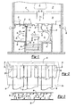
- Figure 1 is a partially schematic side partially cross-sectioned view of one embodiment of the baffle system of this invention
- Figure 2 is a partial side view of Figure 1 in the direction of view arrows 2-2 illustrating one embodiment of the baffle system of this invention
- Figure 3 is a top cross-sectional view of Figure 2 in the direction of view arrows 3-3;
- Figure 4 is a side view similar to Figure 2 illustrating an alternative embodiment of the baffle system shown in Figure 2 ;
- Figure 5 is a top cross-sectional view similar to Figure 3 illustrating an alternative embodiment of the baffle system shown in Figure 3 ;
- Figure 6 is a partial schematic side cross-sectional view similar to Figure 1 illustrating an alternative embodiment of the baffle system of this invention.
- Figure 7 is a graph summarizing one advantage of the baffle system of this invention.
- FIG. 1 illustrates one embodiment of the baffle system of the invention in the environment of a paint spray booth.
- the baffle system of this invention may be utilized in any application to separate entrained liquid from a gas stream and is particularly suitable for separating an entrained liquid from a gas stream, wherein the liquid includes contaminants, such as paint overspray.
- the general configuration of the paint application booth assembly shown in Figure 1 may be conventional including a paint application booth or paint booth 20 which receives the parts to be painted, such as the vehicle body 22, which are generally conveyed into the application booth 20 by a conveyor 24. Paint application equipment (not shown) are located on the floor 26 for application of paint to the vehicle 22.
- the water plenum 28 is located below the application booth 20 which receives water 30 generally including emulsifiers, detackifiers, etc.
- the floor 32 of the water plenum 28 directs the water and paint overspray to the scrubber or scrubbers 36 in the floor 32 of the water plenum 28, which also serves as the ceiling of the scrubber chamber 34.
- the scrubber 36 thoroughly mixes the air and water including airborne particles which are retained with the water 38 directed from the outlet 42 of the scrubber 36 against a wall 40 opposite the outlet 42 which removes the majority of the water and particles from the air.
- the water is then directed into a tank or trough 34 from the floor 45.
- the "wet air” is then directed upwardly by the trough or inlet baffle 46 into the baffles 50 and 52 as shown by arrow 48.
- the columns of baffles 50 and 52 are supported by a bracket 54.
- the dried air is then received in the outlet plenum 59 as shown by arrow 60 where it may be vented to atmosphere.
- the upper wall or back floor section 66 of the plenum 59 is generally inclined to return any moisture back to the tank 44.
- the lower end of the baffles 50 and 52 may be conventionally attached to the side wall 67 (not shown).
- the water 30 is delivered from pumps (not shown) by piping 62 and flows onto the floor of the booth 32 over the weir 64.
- Figure 1 illustrates the improvements to the baffle system of this invention. These improvements will now be described.
- the lower ends 50a and 52a of the baffles 50 and 52 extend into the tank 44 below the level of liquid in the tank.
- the baffles were attached to the vertical portion 67 of the bottom wall 66, but spaced above the liquid in the tank as described above.
- the improvement in efficiency of the baffle system resulting from extending the lower ends 50a and 52a into the tank 44 below the level of liquid in the tank is believed to result from two factors.
- the term "efficiency" of the baffle system relates to the volume of water carried through the baffle system including re-entrained liquid.
- the object of the baffle system is to separate and remove liquid entrained in the gas stream and to reduce or prevent re-entrainment of the liquid in the gas stream flowing through the baffle system.
- the liquid is primarily water which contains paint overspray from the paint spray booth 20, but may also include other contaminants.
- the "efficiency" of the baffle system is determined by the moisture remaining in the air stream 60 after passing through the baffle system.
- the primary object of this invention is the reduce the moisture in the air stream 60 after passing through the baffle system.
- one source of moisture in the air stream 60 results from re-entrainment of the liquid from the baffle system.
- the collection efficiency of the baffle system of this invention was tested by first adding a dye to the water wash 30 and then placing cards at various locations in the baffle system, such as in the chamber 59. The entrained liquid then dyed the cards and the stain level of the cards after a predetermined time were tallied and compared for different baffle systems.
- the flashing system of the baffle system of this invention includes a flashing or flashing plate 56 on the wet side of the baffle system in contact with the wet side baffle members 50 and a flashing or flashing plate 58 on the dry side of the baffle system in contact with the wet side baffle members 52.
- the wet side flashing 56 has a vertical length of at least three times the vertical length of the dry side flashing 58 or preferably the vertical length of the wet side flashing 56 is between three and 10 times the vertical length of the dry side flashing 58.
- the vertical length of the wet side flashing 56 is preferably between four and eight times the vertical length of the dry side flashing 58, most preferably about six times.
- the vertical length of the wet side flashing 56 is preferably at least 5.1 cm (two inches) and may have a vertical length of up to about 30.5 cm (12 inches).
- the reduction of liquid re-entrainment seems to diminish at vertical lengths greater than about 15.2 cm (six inches) and therefore the most preferred vertical length of the web side flashing plate 56 is between 10.2 and 20.3 cm (four and eight inches), most preferably about 15.2 cm (six inches).
- the dry side flashing 58 should have a vertical length of at least 1.3 cm (0.5 inches) and may have a vertical length up to about 7.6 cm (three inches). Greater vertical lengths for the dry side flashing 58 have not been tested.
- FIGs 2 and 3 illustrate one embodiment of the baffle and flashing system of this invention.
- the baffles 50 and 52 of the first and second columns are preferably U-shaped each including a flat web portion 68 and flange portions 70 preferably extending perpendicular to the web portion from the opposed ends of the web portion 68.
- the flashing plates 56 and 58 contact the web portion 68 of the baffle members 50 and 52 as shown in Figure 3 .
- the preferred spacing between the flange portion 70 of the first and second column of baffle members 50 and 52 will be described below.
- the lower edges 56a and 58a of the flashing plates 56 and 58 may be linear and extend perpendicular to the longitudinal axes of the baffle members as shown in Figure 2 .
- the flashing plates 56 and 58 may be attached either to the web portions 68 of the baffle members or to the bracket 50 by any suitable means including fasteners, welding, etc.
- the flashing members 56 and 58 reduce moisture laden air from bypassing the baffle system above the baffles and cause moisture collecting on the flashing plates to flow down the baffles onto the web portions 68 of the baffle members 50 and 52.
- the graph of Figure 7 illustrates the advantage of the baffle system of this invention compared to the baffle system disclosed in the above identified parent application, now U. S. Patent No. 6,290, 742 .
- the tests were conducted by adding a dye to the wash water 30 and placing cards at various locations in the chamber 59. The staining level of the cards after a predetermined period of time were then tallied and compared at different baffle face velocities.
- the percent staining of the cards in the chamber 59 with the baffle system disclosed in U. S. Patent No. 6,290, 742 is shown at 72 and the percent staining of the cards with the baffle system of this invention at 74.
- Figure 7 shows a significant improvement in the baffle system of this invention.
- FIGs 4 and 5 illustrate an alternative embodiment of the baffle system and flashing members shown in Figures 2 and 3 .
- the dry side flashing plate 158 shown in Figure 4 may be characterized as having a saw-tooth configuration engaging the web portions of the baffle members including vertical surfaces 160 engaging the web portion of the baffle members in the second column, angled surfaces 162 intersecting the vertical surface 160 and horizontal surfaces between the "teeth".
- the angle of the angled surface 162 may be any appropriate angle that is not horizontal. However, a 45 degree angle has been found to work well.
- the purpose of the saw-tooth configuration at the lower edge of the dry side of the baffles is to allow any moisture which collects on the bottom edge of the dry side flashing to run off on the web portions of the baffles engaged.
- the angled surface 162 span the adjacent baffles 152 and the vertical surface 160 contact the web portions 168 ( Figure 5 ) so that the liquid runs down to the adjacent baffles. From there, the water will run down to the collection trough or
- FIG 5 also illustrates an alternative embodiment of the baffle members 50 and 52 shown in Figure 2 , wherein the baffle members 150 in the first column of baffles include flange portions 170 which are longer than the flange portions 172 of the second column or dry side baffles 152.
- the baffle members 150 and 152 are preferably U-shaped including a web portion 168 and flange portions 170 and 172 extending generally perpendicular to the web portions 168 at the opposed ends of the web portions 168.
- the flange portions 170 at the wet side of the baffle system are longer than the flange portions 172 at the dry side.
- the flanges 172 may have a length ranging from 40% to 100% of the length of the baffles 170 as shown in Figure 2 .
- the third improvement of the baffle system of this invention relates to the height of the inlet or trough baffle 46.
- Figure 6 illustrates an alternative embodiment of the baffle assembly, wherein the first column or wet side baffle members 250 of the first column of baffles includes a lower baffle plate or flashing 251 attached to the coplanar web portions of the first column of baffles and which extends into the tank or trough 44 beneath the level of the liquid in the tank 44.
- the advantage of extending the columns of baffle members 50 and 52 into the tank 44 below the level of liquid in the tank 44 is to block airflow upwardly from the bottom of the baffles, through the baffles.
- the baffle plate 251 also blocks the upward flow of air through the baffles. If this alternative embodiment is utilized, it has been found advantageous to have the top edge of the baffle plate 251 extend about 15.2 cm (six inches) above the lowest point of the back section floor 66 into the liquid in the tank 44. Both the embodiment shown in Figure 1 and the embodiment shown in Figure 6 thus serve to "plug" the bottom of the baffles, preventing unobstructed vertical airflow through the baffles and thus significantly reducing re-entrainment of liquid on the baffles.
- the third improvement provided by the baffle system of this invention relates to the effective height of the inlet or trough baffle 46.
- the effective height of the trough baffle 46 is measured from the height of the back wall 67 which blocks the flow of air through the lower portion of the baffle system. This dimension is shown at "d" in Figure 1 .
- Conventional trough baffles of this type have an effective height of about 20% of the total length of the baffle columns 50 and 52, wherein the baffle members have a longitudinal length of about 1.98 m (6'6"or 78").
- the purpose of the trough baffle 46 is to deflect any high velocity air moving along the floor of the tank and prevent it from colliding with the bottom portions of the baffle system, causing a localized zone of high velocity.
- the high velocity zone at the bottom of the baffles has been found to contribute materially to re-entrainment because the volume of moisture draining along the baffles is greatest at the lower portions of the baffles.
- the several improvements to the baffle system described above reduce re-entrainment of liquid from the columns of baffles 50 and 52, thereby providing improved efficiency.
- the contaminants in the liquid removed from the gas stream collect on the inside surfaces of the flanges 70 in Figure 3 and 170 and 172 in Figure 5 , particularly where these contaminants are tacky.
- various detackifying agents are generally included in the water stream of a spray booth to reduce the paint overspray particles from adhering to the scrubber 36, the walls o the scrubber chamber 34, the columns of baffles 50 and 52, etc. However, these surfaces must still be cleaned periodically as set forth above.
- the flange portions of the baffle members in the prior art overlapped making it very difficult to clean the inside surfaces of the flange portions. Even where the flange portions do not overlap, however, the person cleaning the baffles cannot view the inside surfaces to determine whether the surfaces have been thoroughly cleaned. That is, there is no line of sight between the columns of baffles 50 and 52 where the flange portions are aligned as disclosed in the above-referenced parent application.
- baffle system of this invention by spacing the flange portions 70 of the adjacent baffle members a distance "f" sufficient to provide a line of sight view of the inside surfaces of the flange portions 70 and facilitate cleaning without materially adversely affecting the collection efficiency of the baffle system. It has been found that the baffles may be spaced 7.6 to 15.2 mm (0.3 to 0.6 inches) without materially decreasing the collection efficiency of the baffle system while providing a line of sight between the baffles 50 and 52.
- the gap "f" between the adjacent flanges 70 may be 2.5 cm (one inch) or more, testing has been conducted with a gap of 1.3 to 9.5 cm (one-half to three-eighths inches) or between 7.6 to 15.2 m m (0.3 and 0.6 inches) without materially adversely affecting the collection efficiency of the baffle system.
- the preferred relationship between the web portion 68 and the flanges 70 in Figure 3 or the web portions 168 and the flanges 170 and 172 in Figure 5 remain as disclosed in the parent application.
- the width of the web portions of the baffle members is at least equal to or greater than three times the length of the flange portions or more preferably at least four times the length of the flange portions.
- the width of the web portions is preferably about 10.2 cm (four inches) or less.
- the web portions 168 may be as much as eight times the length of the flange portions 172. This relationship has provided an unexpected improvement in collection efficiency for the baffle system as discussed more fully in the above- referenced parent application.
- baffle system of this invention Having described the preferred embodiments of the baffle system of this invention, it will be understood that various modifications may be made within the purview of the appended claims. For example, the several improvements to the baffle system of this invention may be utilized separately or individually, superior results in collection efficiency and reduction in re-entrainment of liquid is achieved by using the disclosed inventions in combination.
- said baffle system comprising: a first column of spaced aligned generally U-shaped baffle members each having a web portion and flange portions extending away from a direction of flow of said gas and a second column of spaced aligned generally U-shaped baffle members each having a web portion overlapping a web portion of said first column of baffle members and flange portions extending toward said web portions of said first column of baffle members, wherein said first column of baffle members includes a portion extending into said tank below the level of liquid in said tank.
- each of said baffle members of said first column of spaced aligned generally U-shaped baffle members extends into said tank below said level of liquid in said tank.
- baffle system as defined in numbered embodiment 1, wherein all of said baffle members of said first and second column extend into said tank below said level of liquid in said tank.
- baffle system as defined in numbered embodiment 1, wherein said baffle members of said first column include a plate attached to said web portions extending into said tank below said level of liquid in said tank.
- baffle system as defined in numbered embodiment 1, wherein said baffle members extend generally vertically and said baffle members include a first vertical flashing plate at an upper end of said baffle members of said first column of baffle members blocking flow of gas at said upper end through said baffle members.
- baffle system as defined in numbered embodiment 5, wherein said baffle system includes a second vertical flashing plate on a downstream side of said second column of baffle members having a vertical width less than said first vertical flashing plate.
- baffle system as defined in numbered embodiment 6, wherein said first vertical flashing plate has a vertical length at least three times a vertical length of said second vertical flashing plate.
- baffle system as defined in numbered embodiment 6, wherein said first vertical flashing plate has a vertical length of between 5.1 and 30.5 cm (two and twelve inches).
- baffle system as defined in numbered embodiment 5, wherein said first vertical flashing plate includes relatively sharp edges along its lower extent.
- baffle system as defined in numbered embodiment 1, wherein said baffle system includes a vertical inlet baffle plate spaced upstream of said baffle members extending into said tank having an upper end portion extending toward said direction of flow of gas, wherein said vertical inlet baffle plate has a height of at least 30% of an effective height of said baffle members, wherein said effective height of said baffle members is measured by a vertical length of said baffle members allowing said gas stream to flow unobstructed through said baffle members.
- baffle system as defined in numbered embodiment 1, wherein said flange portions of said baffle members extend generally perpendicular to said web portions and said web portions have a width of at least twice the length of said flange portions, and said flange portions of said first and second column are spaced a distance of between 7.6 and 15.2 mm (0.3 and 0.6 inches).
- baffle system as defined in numbered embodiment 1, wherein said flange portions of said baffle members of said first column of spaced aligned generally U-shaped baffle members have a length of at least three times the length of said flange portions of said second column.
- baffle system as defined in numbered embodiment 12, wherein said length of said flange portions of said baffle members of said first column are longer than a length of said flange portions of said second column.
- baffle system as defined in numbered embodiment 14, wherein said vertical length of said first generally vertical flashing plate is at least three times said vertical length of said second flashing plate.
- baffle system as defined in numbered embodiment 15, wherein said vertical length of said first generally vertical flashing plate is between 5.1 and 30.5 cm (two and 12 inches).
- baffle system as defined in numbered embodiment 15, wherein said vertical length of said second generally vertical flashing plate is between 1.3 and 7.6 cm (0.5 and 3 inches).
- baffle system as defined in numbered embodiment 14, wherein said vertical length of said first generally vertical flashing plate is between three and 10 times said vertical length of said second generally vertical flashing plate.
- baffle system as defined in numbered embodiment 14, wherein said second generally vertical flashing plate includes a lower edge having a plurality of pointed edges.
- baffle system as defined in numbered embodiment 14, wherein said second generally vertical flashing plate includes a lower edge having a plurality of pointed edges formed by vertical edges and an angled edge intersecting said vertical edges forming said pointed edges.
- baffle system as defined in numbered embodiment 14, wherein said first column of baffle members include a portion extending into said tank below a level of said liquid in said tank.
- each of said baffle members of said first column extends into said tank below said level of liquid in said tank.
- baffle system as defined in numbered embodiment 21 , wherein each of said baffle members of said first and second column of baffle members extends into said tank below said level of liquid in said tank.
- baffle system as defined in numbered embodiment 14, wherein said baffle system includes a vertical inlet baffle plate spaced upstream of said first column of baffle members extending into said tank having an upper end extending toward said direction of flow of said gas, wherein said vertical inlet baffle plate has a height of at least 30% of an effective height of said baffle members, wherein said effective height of said baffle members is measured by a length of said baffle members where said gas stream flows unobstructed through said baffle members.
- baffle system as defined in numbered embodiment 14, wherein said flange portions of said baffle members extend generally perpendicular to said web portions and said web portions have a width of at least three times the length of said flange portions, and said flange portions of said first and second columns of baffle members are spaced a distance of between 7.6 and 15.2 mm (0.3 and 0.6 inches).
- baffle system as defined in numbered embodiment 25, wherein said flange portions of said first column of baffle members are longer than said flange portions of said second column of baffle members.
- baffle system as defined in numbered embodiment 14, wherein said flange portions of said baffle members extend generally perpendicular to said web portions and said web portions have a width of at least twice a length of said flange portions and said flange portions of said first and second columns of baffle members spaced a distance of about 1.3 cm (one-half inch).
- baffle system as defined in numbered embodiment 28, wherein said tank includes an outer wall downstream of said direction of flow of said gas and said baffle members extend into said tank below said outer wall, wherein said effective height of said columns of baffle members is measured between an upper surface of said outer wall and an upper surface of said columns of baffle members.
- baffle system as defined in c numbered embodiment 28, wherein said upper end of said inlet baffle has a height of at least 35% of said effective height of said columns of baffle members.
- baffle system as defined in numbered embodiment 28, wherein said first column of baffle members includes a portion extending into said tank below the level of liquid in said tank.
- baffle system as defined in numbered embodiment 28, wherein said first and second columns of baffle members extend into said tank below the level of liquid in said tank.
- baffle system as defined in numbered embodiment 28, wherein said first column of baffle members includes a first flashing plate contacting said web portions at an upper end of said first column of baffle members and a second flashing plate contacting said web portions of the said baffle members of said second column of baffle members.
- baffle system as defined in numbered embodiment 33, wherein the vertical height of said first flashing plate is greater than the vertical height of said second flashing plate.
- baffle system as defined in numbered embodiment 34, wherein said vertical height of said first flashing plate is at least three times said vertical height of said second flashing plate.
- baffle system as defined in numbered embodiment 35, wherein said vertical height of said first flashing plate is between 5.1 and 30.5 cm (two and 12 inches).
- baffle system as defined in numbered embodiment 28, wherein said flange portions of said first and second column of baffle members is spaced a distance of between 7.6 and 15.2 mm (0.3 and 0.6 inches).
Landscapes
- Chemical & Material Sciences (AREA)
- Chemical Kinetics & Catalysis (AREA)
- Separating Particles In Gases By Inertia (AREA)
- Gas Separation By Absorption (AREA)
Abstract
Description
- This invention relates to an improved baffle system for separating entrained liquids from a gas stream. The baffle system of this invention is particularly, but not exclusively suitable for removing contaminants from the air of a work area, such as a paint spray booth having a scrubber system.
- Baffle systems for separating liquid entrained in a gas stream have been used for many years. For example, baffle systems are conventionally used for separating water from an air stream in a paint application system. Paint overspray is removed from the paint application booth by downdraft air. The floor of the booth is flooded with water or water emulsion. The water and paint overspray are then received through scrubbers generally located in the floor below the paint application booth. The gas scrubber removes paint particles from the air in the paint booth, entraining the paint particles in the liquid. The air stream is then passed through baffles, removing the entrained liquid from the air stream.
- A common form of baffle used by the automotive industry in paint application systems, for example, comprise at least two columns of U-shaped rectangular vertical baffles. The baffles each include a web portion and perpendicular flange portions, such that the web portions of the first column of baffles faces the direction of the air flow and the second column of baffles overlaps the baffles in the first column with the flanges extending toward the direction of air flow. The baffle system thus requires the gas stream to flow around the web portions of the first column of baffles into the rectangular U- shaped baffles of the second column of baffles and around the flange portions of the second column of baffles, depositing the liquid on the baffles which flows downwardly and out of the system. The particle size of the liquid droplets or particles is generally greater than about twenty microns (20µ). In a conventional baffle system of this type, the width of the web portion is 20.3 cm (eight inches), the length of the flange portions are 10.2 cm (four inches) and the flange portions overlap 0.635 cm (0.25 inches). The average face velocity measured parallel to the duct in a baffle system for a paint application system of this type is generally between 0.762 to 1.778 m/s (one hundred fifty to three hundred fifty feet per minute (fpm)). The problems with this baffle system include re-entrainment and difficulty cleaning.
- Various attempts have been made to improve the efficiency of baffle systems for removing entrained liquid from a gas stream. For example, the velocity of the gas stream through the baffle system may be increased by overlapping the ends of the flange portions, thereby improving the efficiency of the baffle system. However, a liquid having entrained paint particles will collect between the overlapping flanges requiring more frequent maintenance. It is also more difficult to clean between the overlapping flanges. More importantly, overlapping flanges provide no improvement in the re-entrainment performance of the baffles. Other proposed attempts to improve the efficiency of baffle systems for removing entrained liquid from a gas stream include complex baffle systems including, for example, spiral baffles, baffles having hook-shapes which further increase the velocity of the gas stream through the baffles to improve efficiency, etc. However, such complex baffle systems are relatively expensive to manufacture and require frequent maintenance particularly where a tacky substance, such as paint, is entrained in the liquid droplets or particles. Such complex baffle systems have not been found suitable for removing liquid entrained in a gas stream in a paint application system.
- Thus, there remains a long-felt need for an improved baffle system which is relatively simple in construction, low in cost and having improved efficiency. Further, there is a need to reduce the maintenance costs of conventional baffle systems which reduces the collection of liquid and entrained tacky particles and which is easily cleaned, if necessary. As described below, the improved baffle system of this invention is relatively simple in construction, having reduced costs, particularly when compared to the complex baffle systems described above, and the baffle system of this invention has reduced maintenance costs when compared to baffle systems having overlapping elements.
- This application discloses further improvements made to the baffle system of this invention which improves efficiency by reducing re-entrainment of liquid into the gas stream and improves cleaning of accumulation of contaminants on the baffle system during periodic cleaning of the baffle system of this invention.
- As set forth above, the baffle system of this invention may be utilized in a paint spray booth wherein the water, air and paint overspray is received through a scrubber or scrubbers located in the floor beneath the paint spray booth. The scrubber removes the paint particles from the air in the paint spray booth and entrains the paint particles in the liquid. The liquid received from the scrubbers is then received in a tank or trough located below the scrubber as disclosed, for example, in
U. S. Patent Nos. 5,100, 442 and6,228, 154 assigned to the assignee of the present application. The air is then received through a plurality of baffles where the entrained liquid and paint particles are removed. As will be understood, the efficiency of the baffle system in removing the liquid and entrained particles is critical to the efficiency of the overall system. The baffle system of this invention may also be utilized to separate entrained liquid from a gas stream in other applications. - The baffle system of this invention includes a first column of spaced aligned generally U-shaped baffle members each having a web portion and flange portions extending away from a direction of flow of said gas and a second column of spaced aligned generally U-shaped baffle members each having a web portion overlapping a web portion of said first column of baffle members and flange portions extending toward said web portions of said first column of baffle members, such that each column overlap the adjacent column. The gas flowing through the columns of baffles is thus required to take a tortuous path between the baffles and deposits the liquid on the baffles. In the preferred embodiment, the baffles are suspended vertically and the liquid then flows down the baffles into a tank or trough for further processing. In the preferred embodiment of the baffle system, the flange portions extend generally perpendicular to the web portions from the opposed ends of the web portions and the web portions have a width at least three times the length of the flanges as disclosed in the above-referenced
US patent nos. 5,100,442 and6,228,154 . - The improvements to the baffle system disclosed in this application include (1) extending a portion of at least the first column of baffles into the tank or trough which receives the liquid, (2) providing flashing plates at the upper extent of the baffles in contact with the web portions of the coplanar baffle members, wherein the flashing plate on the first column at the upstream side of the baffle assembly has a greater vertical length than the flashing plate on the second column of baffles at the downstream side, (3) utilizing a vertical inlet baffle plate spaced upstream of the baffle members extending into the tank, wherein the upper end has a height of at least 30% of the effective height of the baffle members, and (4) spacing the flange portions of the baffle members of the first and second columns of baffle members a distance of 7.6 to 15.2 mm (0.3 to 0.6 inches). As will be understood, these improvements may be utilized individually in the baffle system of this invention. However, it has been found that the greatest improvement in collection efficiency results from using these improvements in combination.
- One problem addressed by the improved baffle system of this invention is "re-entrainment" of water droplets on the baffles. As set forth above, the purpose of a baffle system is to remove liquid droplets suspended in a gas stream. The gas stream containing the entrained liquid droplets is directed through the baffle array. The droplets accumulate on the baffles until a liquid film is formed. This liquid film then flows down under the influence of gravity. Ideally, this accumulated liquid flows to the bottom edge of the baffles and runs into a collection system which generally is a tank or trough. As used herein, the term "tank" is intended to cover any pool of liquid located beneath the baffle system, whether or not the tank includes an outlet and is thus technically a trough. As will be understood, re-entrainment of the liquid droplets or film into the air stream defeats the purpose of the baffle system and results in water droplets being re-entrained into the dry air stream which is conventionally vented to atmosphere. In a paint application booth, for example, this can result in increased maintenance requirements for the spray booth and possibly undesirable emissions. Further, where the entrained liquid includes contaminants, such as paint particles received in the wash water from a paint spray booth, the baffle system is subject to fouling by waste or oversprayed paint. Normally, the baffle system and the entire tank is cleaned by high pressure washing, generally semi-annually. This problem was partially solved by spacing the columns or arrays of baffles, such that the flange portions did not overlap. However, fouling still occurs on the inside surfaces of the flange portions of the baffles and it is difficult to clean these areas and there is no line of sight between the baffle members unless the baffles are spaced to confirm that the baffles are cleaned. However, spacing the columns of baffles reduces the overall efficiency of the baffle system, but the baffle system of this invention optimizes the spacing to permit cleaning without a significant loss of efficiency. As set forth above, the present invention addresses these problems to provide improved efficiency and cleanability.
- In a conventional baffle system, the baffles are spaced above the liquid or water in the tank located below the scrubber generally a distance between one inch and one foot. Thus, the air stream can flow upwardly into the baffle system, reducing the overall efficiency of the system. It has now been found that the efficiency of the baffle system of this invention is improved by extending at least a portion of the "wet side" column of baffles into the tank below the level of the liquid in the tank. As used herein, the term "wet side" refers to the first column of baffles at the upstream side of the baffle system which initially receives the gas stream with the entrained liquid. The term "dry side" refers to the second column of baffles at the downstream side of the baffle system. Of course, where the baffle system includes three or more columns of baffles, the "dry side" of the baffle system will be the last column of baffles at the downstream side of the baffle system. Where a baffle plate is utilized to block the flow of air and entrained liquid upwardly into the baffle system, the plate preferably contacts the web portions of the first column of baffles at the wet side of the baffle system and extends into the collection tank below the level of water in the tank. In the preferred embodiment, however, the first column of baffles at the wet side extends into the liquid receiving tank, such that liquid flowing through the channels is received directly in the tank and the air cannot flow upwardly into the baffles. In the most preferred embodiment, the lower ends of both the first and second column of baffles extends into the tank below the liquid level providing the greatest improvement in efficiency.
- Another improvement in efficiency provided by the baffle system of this invention is providing flashing at the top of the baffle system. The baffle array is normally suspended vertically by a bracket attached to the ceiling of the scrubber tank chamber located beneath the paint spray booth. Even in an ideal installation, water droplets collect on the lower surface of the bracket and the moisture then accumulates on the second column of baffles on the downstream or dry side of the baffle system, where the moisture is re-entrained in the airflow through the baffles. The baffle system of this invention prevents this moisture collected on the bracket from reaching the second column and thereby results in improved collection efficiency. The baffle system of this invention includes a flashing system comprising a flashing plate at both the dry and wet sides of the columns of baffle members at the top of the baffles, wherein the flashing on the wet side of the first column of baffle members has a greater vertical length than the flashing on the dry side. In the preferred embodiment, the vertical length of the flashing plate on the wet side or the first column of baffle members is at least three times the vertical length of the flashing plate on the dry side or preferably between three and 10 times the vertical length of the flashing plate on the dry side. Experimentation has established that the greatest efficiency is achieved by providing a flashing plate contacting the web portions of the first column of baffle members having a vertical length of between 5.1 to 30.5 cm ( two inches to 12 inches), preferably between 10.2 and 20.3 cm (four and eight inches) and most preferably about 15.2 cm (six inches). The flashing contacting the web portions on the second column of baffle members or dry side preferably has a vertical length between 1.3 and 7.6cm (one-half inch and three inches). Although the improvement in efficiency provided by the flashing plates is not fully understood, experimentation has established that the greatest efficiency is provided by a flashing plate on the wet side of the first column of baffle members should have a length of about 15.2 cm (six inches) and the flashing plate on the dry side should have a vertical length of at least 1.3 cm (one-half inch) and may have a vertical length of up to about 7.6 cm (three inches). The lower edge of the dry side flashing plate may be straight or more preferably may include a plurality of angled edges, wherein moisture that collects on the lower edge of the dry side flashing plate runs off onto the baffles. In the most preferred embodiment, the lower angled edges of the dry side flashing plate include a plurality of relatively sharp edges formed by a vertical surface and an angled surface intersecting the vertical surface promoting runoff of the moisture collected on the bottom edge onto the baffles. The angled surface can be any angle which is not horizontal and a 45 degree angle has been found to work well.
- It has also been found that a further improvement in liquid collection efficiency of a baffle system of the type disclosed herein is provided by directing the inlet air upwardly at a relatively sharp angle into the column of baffles. This is because the lower portions of the baffles have the greater volume of liquid, but the velocity of air flowing through the baffle system is greater in the lower portion in a conventional baffle system, resulting in re-entrainment of liquid in the gas stream. In the present invention, the air stream is directed upwardly by an inlet or trough baffle spaced from the first and second baffles having a lower end in the tank and an upper end including a flange portion extending toward the inlet stream as is known in the prior art. However, experimentation with the height of the inlet baffle has established that a significant improvement in efficiency can be achieved by raising the inlet or trough baffle to direct the incoming gas upwardly at a steeper angle. In a conventional baffle system, the dry side baffle column is attached to a floor section which forms the downstream side of the tank and which blocks the flow of gas through the bottom of the baffles. Thus, the "effective height" of the inlet or trough baffle is measured from the top of the floor section to which the dry side baffles are attached. In a baffle system having a vertical length of 1.98 m (6'6"or 78"), the inlet baffle normally extends about 0.43 m (17") above the floor section to which the dry side baffles are attached or about 20% of the height of the baffles measured from the top of the floor section. However, experimentation has established that by extending the inlet baffle at least 30% or more preferably about 35% of the effective height of the baffles measured from the top of the floor section results in a significant improvement in the efficiency of the baffle system. Again, the reason for this significant improvement is not fully understood, but it is believed that the improvement results from directing the gas stream upwardly at a steeper angle into the baffle columns thereby reducing the velocity of the air stream in the lower portion of the baffles.
- Finally, as set forth above, spacing the columns of baffles sufficiently to permit visualization and cleaning of the inside surfaces of the flange portions does not materially reduce the efficiency of the baffle system, provided the spacing is relatively small. In the preferred embodiment, the baffle system comprises a plurality of spaced generally U-shaped baffle members, wherein each baffle member includes a web portion and a flange portion extending generally perpendicular from the opposed sides of the web portion including a first column of baffle members having flange portions extending away from the direction of flow of the gas stream and a second adjacent column of baffle members each having a flange portion extending toward the web portions of the first column in overlapping relation. As set forth in the above-referenced parent application, it has been found that a significant improvement in efficiency results from dimensioning the baffle members wherein the width of the web portions of the baffle members is equal to or greater than three times the length of the flange portions and the flange portions of the columns of baffle members do not overlap. However, as set forth above, experimentation has now established that the flange portions of the adjacent columns may be spaced a distance of between 7.6 and 15.2 mm (0.3 and 0.6 inches) without a material loss of efficiency. This spacing, however, permits cleaning and visualization of the flange portions between the columns, thereby assuring complete cleaning of the baffle members and therefore improved efficiency.
- Other advantages and meritorious features of the baffle system of this invention will be more fully understood from the following description of the preferred embodiments, the appended claims and the drawings, a brief description of which follows.
-
Figure 1 is a partially schematic side partially cross-sectioned view of one embodiment of the baffle system of this invention; -
Figure 2 is a partial side view ofFigure 1 in the direction of view arrows 2-2 illustrating one embodiment of the baffle system of this invention; -
Figure 3 is a top cross-sectional view ofFigure 2 in the direction of view arrows 3-3; -
Figure 4 is a side view similar toFigure 2 illustrating an alternative embodiment of the baffle system shown inFigure 2 ; -
Figure 5 is a top cross-sectional view similar toFigure 3 illustrating an alternative embodiment of the baffle system shown inFigure 3 ; -
Figure 6 is a partial schematic side cross-sectional view similar toFigure 1 illustrating an alternative embodiment of the baffle system of this invention; and -
Figure 7 is a graph summarizing one advantage of the baffle system of this invention. -
Figure 1 illustrates one embodiment of the baffle system of the invention in the environment of a paint spray booth. As set forth above, however, the baffle system of this invention may be utilized in any application to separate entrained liquid from a gas stream and is particularly suitable for separating an entrained liquid from a gas stream, wherein the liquid includes contaminants, such as paint overspray. The general configuration of the paint application booth assembly shown inFigure 1 may be conventional including a paint application booth orpaint booth 20 which receives the parts to be painted, such as thevehicle body 22, which are generally conveyed into theapplication booth 20 by aconveyor 24. Paint application equipment (not shown) are located on thefloor 26 for application of paint to thevehicle 22. Thewater plenum 28 is located below theapplication booth 20 which receiveswater 30 generally including emulsifiers, detackifiers, etc. Thefloor 32 of thewater plenum 28 directs the water and paint overspray to the scrubber orscrubbers 36 in thefloor 32 of thewater plenum 28, which also serves as the ceiling of the scrubber chamber 34. Thescrubber 36 thoroughly mixes the air and water including airborne particles which are retained with thewater 38 directed from the outlet 42 of thescrubber 36 against awall 40 opposite the outlet 42 which removes the majority of the water and particles from the air. The water is then directed into a tank or trough 34 from thefloor 45. The "wet air" is then directed upwardly by the trough orinlet baffle 46 into thebaffles arrow 48. The columns ofbaffles bracket 54. The dried air is then received in the outlet plenum 59 as shown byarrow 60 where it may be vented to atmosphere. The upper wall or backfloor section 66 of the plenum 59 is generally inclined to return any moisture back to thetank 44. The lower end of thebaffles water 30 is delivered from pumps (not shown) by piping 62 and flows onto the floor of thebooth 32 over theweir 64. - As stated above, the booth assembly shown in
Figure 1 is generally conventionally. However,Figure 1 also illustrates the improvements to the baffle system of this invention. These improvements will now be described. First, as shown inFigure 1 , the lower ends 50a and 52a of thebaffles tank 44 below the level of liquid in the tank. Previously, the baffles were attached to thevertical portion 67 of thebottom wall 66, but spaced above the liquid in the tank as described above. The improvement in efficiency of the baffle system resulting from extending the lower ends 50a and 52a into thetank 44 below the level of liquid in the tank is believed to result from two factors. First, it was found that moisture laden air could flow unobstructed upwardly through the baffles because the air can flow upwardly parallel to the baffles without obstruction. Thus, the velocity of the moisture laden air through this area can become great enough to re-entrain collected liquid running down the baffles. The liquid in thetank 44 thus serves to "plug" the lower ends of the baffles, preventing air from flowing upwardly through the baffles. Also, extending the baffles into the water promotes collection of water in thetank 44. As used herein, the term "efficiency" of the baffle system relates to the volume of water carried through the baffle system including re-entrained liquid. That is, the object of the baffle system is to separate and remove liquid entrained in the gas stream and to reduce or prevent re-entrainment of the liquid in the gas stream flowing through the baffle system. As set forth above, in a paint spray booth, the liquid is primarily water which contains paint overspray from thepaint spray booth 20, but may also include other contaminants. Thus, the "efficiency" of the baffle system is determined by the moisture remaining in theair stream 60 after passing through the baffle system. The primary object of this invention is the reduce the moisture in theair stream 60 after passing through the baffle system. However, it has now been found that one source of moisture in theair stream 60 results from re-entrainment of the liquid from the baffle system. The collection efficiency of the baffle system of this invention was tested by first adding a dye to thewater wash 30 and then placing cards at various locations in the baffle system, such as in the chamber 59. The entrained liquid then dyed the cards and the stain level of the cards after a predetermined time were tallied and compared for different baffle systems. - A second improvement resulted from the addition of the flashing
plates Figure 1 and the embodiments of the flashing plates shown inFigure 2-5 as now discussed. As shown inFigure 1 , the flashing system of the baffle system of this invention includes a flashing or flashingplate 56 on the wet side of the baffle system in contact with the wetside baffle members 50 and a flashing or flashingplate 58 on the dry side of the baffle system in contact with the wetside baffle members 52. In the preferred embodiment, the wet side flashing 56 has a vertical length of at least three times the vertical length of the dry side flashing 58 or preferably the vertical length of the wet side flashing 56 is between three and 10 times the vertical length of the dry side flashing 58. Experimentation and testing has established that the vertical length of the wet side flashing 56 is preferably between four and eight times the vertical length of the dry side flashing 58, most preferably about six times. The vertical length of the wet side flashing 56 is preferably at least 5.1 cm (two inches) and may have a vertical length of up to about 30.5 cm (12 inches). The reduction of liquid re-entrainment seems to diminish at vertical lengths greater than about 15.2 cm (six inches) and therefore the most preferred vertical length of the webside flashing plate 56 is between 10.2 and 20.3 cm (four and eight inches), most preferably about 15.2 cm (six inches). It has also been found that the dry side flashing 58 should have a vertical length of at least 1.3 cm (0.5 inches) and may have a vertical length up to about 7.6 cm (three inches). Greater vertical lengths for the dry side flashing 58 have not been tested. -
Figures 2 and 3 illustrate one embodiment of the baffle and flashing system of this invention. Thebaffles flat web portion 68 andflange portions 70 preferably extending perpendicular to the web portion from the opposed ends of theweb portion 68. The flashingplates web portion 68 of thebaffle members Figure 3 . The preferred spacing between theflange portion 70 of the first and second column ofbaffle members lower edges plates Figure 2 . The flashingplates web portions 68 of the baffle members or to thebracket 50 by any suitable means including fasteners, welding, etc. - The improvement in collection efficiency and reduction of re-entrainment provided by the flashing
members members web portions 68 of thebaffle members - The graph of
Figure 7 illustrates the advantage of the baffle system of this invention compared to the baffle system disclosed in the above identified parent application, nowU. S. Patent No. 6,290, 742 . As set forth above, the tests were conducted by adding a dye to thewash water 30 and placing cards at various locations in the chamber 59. The staining level of the cards after a predetermined period of time were then tallied and compared at different baffle face velocities. InFigure 7 , the percent staining of the cards in the chamber 59 with the baffle system disclosed inU. S. Patent No. 6,290, 742 is shown at 72 and the percent staining of the cards with the baffle system of this invention at 74. Thus,Figure 7 shows a significant improvement in the baffle system of this invention. -
Figures 4 and 5 illustrate an alternative embodiment of the baffle system and flashing members shown inFigures 2 and 3 . The dryside flashing plate 158 shown inFigure 4 may be characterized as having a saw-tooth configuration engaging the web portions of the baffle members includingvertical surfaces 160 engaging the web portion of the baffle members in the second column, angledsurfaces 162 intersecting thevertical surface 160 and horizontal surfaces between the "teeth". The angle of theangled surface 162 may be any appropriate angle that is not horizontal. However, a 45 degree angle has been found to work well. The purpose of the saw-tooth configuration at the lower edge of the dry side of the baffles is to allow any moisture which collects on the bottom edge of the dry side flashing to run off on the web portions of the baffles engaged. Theangled surface 162 span theadjacent baffles 152 and thevertical surface 160 contact the web portions 168 (Figure 5 ) so that the liquid runs down to the adjacent baffles. From there, the water will run down to the collection trough ortank 44. -
Figure 5 also illustrates an alternative embodiment of thebaffle members Figure 2 , wherein thebaffle members 150 in the first column of baffles includeflange portions 170 which are longer than theflange portions 172 of the second column or dry side baffles 152. As described above, thebaffle members web portion 168 andflange portions web portions 168 at the opposed ends of theweb portions 168. However, in this embodiment, theflange portions 170 at the wet side of the baffle system are longer than theflange portions 172 at the dry side. Although this configuration has not yet been tested, computer modeling has indicated that it may be advantageous in reducing re-entrainment of liquid on the baffle members. Theflanges 172 may have a length ranging from 40% to 100% of the length of thebaffles 170 as shown inFigure 2 . - The third improvement of the baffle system of this invention relates to the height of the inlet or
trough baffle 46.Figure 6 illustrates an alternative embodiment of the baffle assembly, wherein the first column or wetside baffle members 250 of the first column of baffles includes a lower baffle plate or flashing 251 attached to the coplanar web portions of the first column of baffles and which extends into the tank ortrough 44 beneath the level of the liquid in thetank 44. As set forth above, the advantage of extending the columns ofbaffle members tank 44 below the level of liquid in thetank 44 is to block airflow upwardly from the bottom of the baffles, through the baffles. Because the air or gas can flow upwardly parallel to the baffles without obstruction, the velocity of the gas in this area can become high enough to re-entrain collected water running down from the upper portions of the baffles. Thus, thebaffle plate 251 also blocks the upward flow of air through the baffles. If this alternative embodiment is utilized, it has been found advantageous to have the top edge of thebaffle plate 251 extend about 15.2 cm (six inches) above the lowest point of theback section floor 66 into the liquid in thetank 44. Both the embodiment shown inFigure 1 and the embodiment shown inFigure 6 thus serve to "plug" the bottom of the baffles, preventing unobstructed vertical airflow through the baffles and thus significantly reducing re-entrainment of liquid on the baffles. - The third improvement provided by the baffle system of this invention relates to the effective height of the inlet or
trough baffle 46. As set forth above, the effective height of thetrough baffle 46 is measured from the height of theback wall 67 which blocks the flow of air through the lower portion of the baffle system. This dimension is shown at "d" inFigure 1 . Conventional trough baffles of this type have an effective height of about 20% of the total length of thebaffle columns trough baffle 46 is to deflect any high velocity air moving along the floor of the tank and prevent it from colliding with the bottom portions of the baffle system, causing a localized zone of high velocity. The high velocity zone at the bottom of the baffles has been found to contribute materially to re-entrainment because the volume of moisture draining along the baffles is greatest at the lower portions of the baffles. By increasing the effective height "d" of thetrough baffle 46 to at least 30% or more preferably 35%, the velocity of the airflow at the lower portion of the baffles is reduced, thereby reducing re-entrainment of liquid flowing downwardly on the baffles where the volume of liquid is the greatest. - As set forth above, the several improvements to the baffle system described above reduce re-entrainment of liquid from the columns of
baffles flanges 70 inFigure 3 and 170 and 172 inFigure 5 , particularly where these contaminants are tacky. As will be understood by those skilled in this art, various detackifying agents are generally included in the water stream of a spray booth to reduce the paint overspray particles from adhering to thescrubber 36, the walls o the scrubber chamber 34, the columns ofbaffles baffles flange portions 70 of the adjacent baffle members a distance "f" sufficient to provide a line of sight view of the inside surfaces of theflange portions 70 and facilitate cleaning without materially adversely affecting the collection efficiency of the baffle system. It has been found that the baffles may be spaced 7.6 to 15.2 mm (0.3 to 0.6 inches) without materially decreasing the collection efficiency of the baffle system while providing a line of sight between thebaffles adjacent flanges 70 may be 2.5 cm (one inch) or more, testing has been conducted with a gap of 1.3 to 9.5 cm (one-half to three-eighths inches) or between 7.6 to 15.2 m m (0.3 and 0.6 inches) without materially adversely affecting the collection efficiency of the baffle system. The preferred relationship between theweb portion 68 and theflanges 70 inFigure 3 or theweb portions 168 and theflanges Figure 5 remain as disclosed in the parent application. That is, in the preferred embodiment of the baffle system of this invention, the width of the web portions of the baffle members is at least equal to or greater than three times the length of the flange portions or more preferably at least four times the length of the flange portions. The width of the web portions is preferably about 10.2 cm (four inches) or less. In the embodiment shown inFigure 4 , theweb portions 168 may be as much as eight times the length of theflange portions 172. This relationship has provided an unexpected improvement in collection efficiency for the baffle system as discussed more fully in the above- referenced parent application. - Having described the preferred embodiments of the baffle system of this invention, it will be understood that various modifications may be made within the purview of the appended claims. For example, the several improvements to the baffle system of this invention may be utilized separately or individually, superior results in collection efficiency and reduction in re-entrainment of liquid is achieved by using the disclosed inventions in combination.
- A baffle system for separating entrained liquid from a gas stream flowing through said scrubber, wherein said liquid is collected in said tank located below said scrubber with said tank containing said liquid at a generally predetermined level, said baffle system comprising: a first column of spaced aligned generally U-shaped baffle members each having a web portion and flange portions extending away from a direction of flow of said gas and a second column of spaced aligned generally U-shaped baffle members each having a web portion overlapping a web portion of said first column of baffle members and flange portions extending toward said web portions of said first column of baffle members, wherein said first column of baffle members includes a portion extending into said tank below the level of liquid in said tank.
- The baffle system as defined in numbered embodiment 1, wherein each of said baffle members of said first column of spaced aligned generally U-shaped baffle members extends into said tank below said level of liquid in said tank.
- The baffle system as defined in numbered embodiment 1, wherein all of said baffle members of said first and second column extend into said tank below said level of liquid in said tank.
- The baffle system as defined in numbered embodiment 1, wherein said baffle members of said first column include a plate attached to said web portions extending into said tank below said level of liquid in said tank.
- The baffle system as defined in numbered embodiment 1, wherein said baffle members extend generally vertically and said baffle members include a first vertical flashing plate at an upper end of said baffle members of said first column of baffle members blocking flow of gas at said upper end through said baffle members.
- The baffle system as defined in numbered
embodiment 5, wherein said baffle system includes a second vertical flashing plate on a downstream side of said second column of baffle members having a vertical width less than said first vertical flashing plate. - The baffle system as defined in numbered embodiment 6, wherein said first vertical flashing plate has a vertical length at least three times a vertical length of said second vertical flashing plate.
- The baffle system as defined in numbered embodiment 6, wherein said first vertical flashing plate has a vertical length of between 5.1 and 30.5 cm (two and twelve inches).
- The baffle system as defined in numbered
embodiment 5, wherein said first vertical flashing plate includes relatively sharp edges along its lower extent. - The baffle system as defined in numbered embodiment 1, wherein said baffle system includes a vertical inlet baffle plate spaced upstream of said baffle members extending into said tank having an upper end portion extending toward said direction of flow of gas, wherein said vertical inlet baffle plate has a height of at least 30% of an effective height of said baffle members, wherein said effective height of said baffle members is measured by a vertical length of said baffle members allowing said gas stream to flow unobstructed through said baffle members.
- The baffle system as defined in numbered embodiment 1, wherein said flange portions of said baffle members extend generally perpendicular to said web portions and said web portions have a width of at least twice the length of said flange portions, and said flange portions of said first and second column are spaced a distance of between 7.6 and 15.2 mm (0.3 and 0.6 inches).
- The baffle system as defined in numbered embodiment 1, wherein said flange portions of said baffle members of said first column of spaced aligned generally U-shaped baffle members have a length of at least three times the length of said flange portions of said second column.
- The baffle system as defined in numbered embodiment 12, wherein said length of said flange portions of said baffle members of said first column are longer than a length of said flange portions of said second column.
- A baffle system for separating entrained liquid from a gas stream flowing through a scrubber, wherein said liquid is collected in a tank located below said scrubber, said baffle system comprising: a first generally vertically extending column of spaced aligned generally U-shaped baffle members each having a web portion and flange portions extending away from a direction of flow of said gas and a second generally vertical column of spaced aligned generally U-shaped baffle members each having a web portion overlapping a web portion of said first column of baffle members and flange portions extending toward said web portions of said first column of baffle members, a first generally vertical flashing plate contacting an upper end of said web portions of said first column of baffle members and a second generally vertical flashing plate contacting an upper end of said second column of baffle members, wherein said first generally vertical flashing plate has a vertical length greater than said second generally vertical flashing plate.
- The baffle system as defined in numbered embodiment 14, wherein said vertical length of said first generally vertical flashing plate is at least three times said vertical length of said second flashing plate.
- The baffle system as defined in numbered embodiment 15, wherein said vertical length of said first generally vertical flashing plate is between 5.1 and 30.5 cm (two and 12 inches).
- The baffle system as defined in numbered embodiment 15, wherein said vertical length of said second generally vertical flashing plate is between 1.3 and 7.6 cm (0.5 and 3 inches).
- The baffle system as defined in numbered embodiment 14, wherein said vertical length of said first generally vertical flashing plate is between three and 10 times said vertical length of said second generally vertical flashing plate.
- The baffle system as defined in numbered embodiment 14, wherein said second generally vertical flashing plate includes a lower edge having a plurality of pointed edges.
- The baffle system as defined in numbered embodiment 14, wherein said second generally vertical flashing plate includes a lower edge having a plurality of pointed edges formed by vertical edges and an angled edge intersecting said vertical edges forming said pointed edges.
- The baffle system as defined in numbered embodiment 14, wherein said first column of baffle members include a portion extending into said tank below a level of said liquid in said tank.
- The baffle system as defined in numbered
embodiment 21, wherein each of said baffle members of said first column extends into said tank below said level of liquid in said tank. - The baffle system as defined in numbered
embodiment 21 , wherein each of said baffle members of said first and second column of baffle members extends into said tank below said level of liquid in said tank. - The baffle system as defined in numbered embodiment 14, wherein said baffle system includes a vertical inlet baffle plate spaced upstream of said first column of baffle members extending into said tank having an upper end extending toward said direction of flow of said gas, wherein said vertical inlet baffle plate has a height of at least 30% of an effective height of said baffle members, wherein said effective height of said baffle members is measured by a length of said baffle members where said gas stream flows unobstructed through said baffle members.
- The baffle system as defined in numbered embodiment 14, wherein said flange portions of said baffle members extend generally perpendicular to said web portions and said web portions have a width of at least three times the length of said flange portions, and said flange portions of said first and second columns of baffle members are spaced a distance of between 7.6 and 15.2 mm (0.3 and 0.6 inches).
- The baffle system as defined in numbered embodiment 25, wherein said flange portions of said first column of baffle members are longer than said flange portions of said second column of baffle members.
- The baffle system as defined in numbered embodiment 14, wherein said flange portions of said baffle members extend generally perpendicular to said web portions and said web portions have a width of at least twice a length of said flange portions and said flange portions of said first and second columns of baffle members spaced a distance of about 1.3 cm (one-half inch).
- A baffle system for separating entrained liquid from a gas stream flowing through a scrubber, wherein said liquid is collected in a tank located below said scrubber, said baffle system comprising: a first vertical column of spaced aligned generally U-shaped baffle members each having a web portion and flange portions extending away from a direction of flow of said gas and a second vertical column of spaced aligned generally U-shaped baffle members each having a web portion overlapping a web portion of said first column of baffle members and flange portions extending toward said web portions of said first column of baffle members, and an inlet baffle spaced upstream of said direction of flow of said gas of said first column of baffle members having a lower end in said tank and an upper end having a height of at least thirty percent of an effective height of said columns of baffle members, wherein said effective height of said columns of baffle members is measured by the vertical length of said baffle members where said flow of said gas is unobstructed.
- The baffle system as defined in numbered
embodiment 28, wherein said tank includes an outer wall downstream of said direction of flow of said gas and said baffle members extend into said tank below said outer wall, wherein said effective height of said columns of baffle members is measured between an upper surface of said outer wall and an upper surface of said columns of baffle members. - The baffle system as defined in c numbered
embodiment 28, wherein said upper end of said inlet baffle has a height of at least 35% of said effective height of said columns of baffle members. - The baffle system as defined in numbered
embodiment 28, wherein said first column of baffle members includes a portion extending into said tank below the level of liquid in said tank. - The baffle system as defined in numbered
embodiment 28, wherein said first and second columns of baffle members extend into said tank below the level of liquid in said tank. - The baffle system as defined in numbered
embodiment 28, wherein said first column of baffle members includes a first flashing plate contacting said web portions at an upper end of said first column of baffle members and a second flashing plate contacting said web portions of the said baffle members of said second column of baffle members. - The baffle system as defined in numbered embodiment 33, wherein the vertical height of said first flashing plate is greater than the vertical height of said second flashing plate.
- The baffle system as defined in numbered embodiment 34, wherein said vertical height of said first flashing plate is at least three times said vertical height of said second flashing plate.
- The baffle system as defined in numbered embodiment 35, wherein said vertical height of said first flashing plate is between 5.1 and 30.5 cm (two and 12 inches).
- The baffle system as defined in numbered
embodiment 28, wherein said flange portions of said first and second column of baffle members is spaced a distance of between 7.6 and 15.2 mm (0.3 and 0.6 inches).
Claims (12)
- A baffle system for separating entrained liquid from a gas stream, comprising: a plurality of generally coplanar columns, each column comprising a plurality of spaced generally upright U-shaped baffle members, each baffle member having a web portion and flange portions extending from opposite sides of said web portions each having a free end, including a first column of baffle members having said flange portions of said baffle members extending away from a direction of flow of said gas stream and a second adjacent column of said baffle members having web portions overlapping said first column of baffle members, wherein the width of said web portions of each of said baffle members is equal to or greater than three times the length of said flange portions and said flange portions of said first and second column of baffle members are spaced a distance of between 7.6 and 15.2 mm (0.3 and 0.6 inches).
- The baffle system as defined in claim 1, wherein said first column of baffle members includes a portion extending into a tank of liquid below the level of said liquid.
- The baffle system as defined in claim 2, wherein said baffle members of said first column of baffle members extends into said tank below said level of said liquid.
- The baffle system as defined in claim 2, wherein said baffle members of said first and second column of baffle members extending into said tank below said level of liquid.
- The baffle system as defined in claim 1, wherein said baffle system includes a first generally vertical flashing plate contacting an upper end of said web portions of said first column of baffle members and a second generally vertical flashing plate contacting an upper end of said web portions of said second column of baffle members, wherein said first generally vertical flashing plate has a vertical length greater than said second vertical flashing plate.
- The baffle system as defined in claim 5, wherein said vertical length of said first generally vertical flashing plate is at least three times said vertical length of said second generally vertical flashing plate.
- The baffle system as defined in claim 6, wherein said vertical length of said first generally vertical flashing plate is between 5.1 and 30.5 cm (two and 12 inches).
- The baffle system as defined in claim 5, wherein said vertical length of said second generally vertical flashing plate is between 1.3 and 7.6 cm (0.5 and three inches).
- The baffle system as defined in claim 8, wherein said vertical length of said first generally vertical flashing plate is between 5.1 and 30.5 cm (two and 12 inches).
- The baffle system as defined in claim 5, wherein said second generally vertical flashing plate includes a lower edge having a plurality of relatively sharp edges pointing downwardly.
- The baffle system as defined in claim 10, wherein said sharp edges are defined by a plurality of generally vertical edges and edges angled upwardly intersecting said generally vertical edges.
- The baffle system as defined in claim 1, wherein said baffle system includes a generally vertical inlet baffle plate spaced upstream of said first column of baffle members extending into a tank receiving said liquid including an upper end extending toward said direction of flow of said gas stream, wherein said generally vertical inlet baffle plate has a height of at least 30% of the effective height of said baffle members.
Applications Claiming Priority (3)
| Application Number | Priority Date | Filing Date | Title |
|---|---|---|---|
| US31891201P | 2001-09-12 | 2001-09-12 | |
| US10/040,737 US6623551B2 (en) | 2001-09-12 | 2002-01-07 | Baffle system for separating liquid from a gas stream |
| EP02757078A EP1432492A2 (en) | 2001-09-12 | 2002-08-13 | Baffle system for separating liquid from a gas stream |
Related Parent Applications (2)
| Application Number | Title | Priority Date | Filing Date |
|---|---|---|---|
| EP02757078A Division EP1432492A2 (en) | 2001-09-12 | 2002-08-13 | Baffle system for separating liquid from a gas stream |
| EP02757078.7 Division | 2002-08-13 |
Publications (2)
| Publication Number | Publication Date |
|---|---|
| EP2236186A1 true EP2236186A1 (en) | 2010-10-06 |
| EP2236186B1 EP2236186B1 (en) | 2012-10-17 |
Family
ID=26717361
Family Applications (2)
| Application Number | Title | Priority Date | Filing Date |
|---|---|---|---|
| EP02757078A Ceased EP1432492A2 (en) | 2001-09-12 | 2002-08-13 | Baffle system for separating liquid from a gas stream |
| EP10167966A Expired - Lifetime EP2236186B1 (en) | 2001-09-12 | 2002-08-13 | Baffle system for separating liquid from a gas stream |
Family Applications Before (1)
| Application Number | Title | Priority Date | Filing Date |
|---|---|---|---|
| EP02757078A Ceased EP1432492A2 (en) | 2001-09-12 | 2002-08-13 | Baffle system for separating liquid from a gas stream |
Country Status (6)
| Country | Link |
|---|---|
| US (1) | US6623551B2 (en) |
| EP (2) | EP1432492A2 (en) |
| AU (1) | AU2002323117A1 (en) |
| CA (1) | CA2428182C (en) |
| MX (1) | MXPA03004142A (en) |
| WO (1) | WO2003022403A2 (en) |
Families Citing this family (9)
| Publication number | Priority date | Publication date | Assignee | Title |
|---|---|---|---|---|
| US20050000199A1 (en) * | 2003-05-27 | 2005-01-06 | Caddy Corporation | Baffle filter |
| WO2006041451A1 (en) | 2004-09-29 | 2006-04-20 | Durr Industries, Inc. | Production paint shop design |
| MY149598A (en) * | 2006-07-20 | 2013-09-13 | Sanyo Electric Co | Air filtering apparatus having foreign material removing mechanism |
| US7947123B2 (en) | 2006-11-10 | 2011-05-24 | Illinois Tool Works Inc. | Impact filter with grease trap |
| DE102007015150A1 (en) * | 2007-03-02 | 2008-09-04 | Wurster, Gerd | Paint spraying plant with booth, has separate air conditioning equipment for coating zone and air supplies for auxiliary zones on either side |
| CN104894501A (en) * | 2015-05-21 | 2015-09-09 | 广东省工业技术研究院(广州有色金属研究院) | Powder gathering device for powder feeding amount measurement of thermal spraying |
| CN106669344A (en) * | 2017-01-19 | 2017-05-17 | 眉山市大地缘农业服务有限公司 | Grain drying machine dust chamber |
| CN109011858B (en) * | 2018-09-03 | 2020-09-01 | 芜湖华洁环保设备有限公司 | Dehydration tower used after washing of converter flue gas |
| CN111804103B (en) * | 2020-07-01 | 2021-09-07 | 河南城建学院 | A road construction dust suppression device |
Citations (7)
| Publication number | Priority date | Publication date | Assignee | Title |
|---|---|---|---|---|
| GB497395A (en) * | 1936-08-10 | 1938-12-16 | Hans Wittemeier | Improvements in or relating to filters or purifiers for air or other gases or for vapours |
| US3932151A (en) * | 1973-02-12 | 1976-01-13 | Binks Manufacturing Company | Spray booth |
| FR2325413A1 (en) * | 1975-09-26 | 1977-04-22 | Zundel Marcel | Removing liq. droplets and solid particles from gases - using a separator which incorporates a series of vertical grids |
| EP0415511A1 (en) * | 1989-08-31 | 1991-03-06 | Haden Schweitzer Corporation | Air cleaning apparatus |
| US5100442A (en) | 1991-04-29 | 1992-03-31 | Durr Industries, Inc. | Gas scrubber system |
| US6228154B1 (en) | 1999-12-23 | 2001-05-08 | Durr Industries, Inc. | Discrete venturi gas scrubber system |
| WO2001047617A1 (en) * | 1999-12-23 | 2001-07-05 | Durr Industries, Inc. | Baffle system for separating liquid from a gas stream |
Family Cites Families (38)
| Publication number | Priority date | Publication date | Assignee | Title |
|---|---|---|---|---|
| US752194A (en) * | 1904-02-16 | Wasmikgtm | ||
| US808897A (en) * | 1904-09-16 | 1906-01-02 | Buffalo Forge Co | Apparatus for treating air. |
| US1147484A (en) * | 1909-04-15 | 1915-07-20 | Stuart W Cramer | Air-conditioning apparatus. |
| US1117309A (en) * | 1914-06-05 | 1914-11-17 | Harry Bentz | Gas-washer. |
| US1223082A (en) * | 1916-08-17 | 1917-04-17 | Adolph W Lissauer | Compressible-fluid washer. |
| US1402147A (en) * | 1919-09-18 | 1922-01-03 | Buffalo Forge Co | Air washer and the like |
| US2474540A (en) * | 1946-02-09 | 1949-06-28 | Fluor Corp | Gas separator |
| US2583390A (en) * | 1949-09-01 | 1952-01-22 | Jens A Paasche | Water wash booth |
| US2655905A (en) * | 1950-08-26 | 1953-10-20 | Springfield Boiler Company | Steam purifier |
| US2694466A (en) * | 1953-02-20 | 1954-11-16 | R C Mahon Company | Paint spray eliminator |
| US2976954A (en) * | 1959-06-04 | 1961-03-28 | Henry Pope R | Compressed air purifier |
| DE1427897C3 (en) * | 1961-12-22 | 1975-03-20 | Hoestemberghe & Kluetsch Gmbh, 6630 Saarlouis | Cooling bed for square rolled material |
| US3566585A (en) * | 1969-07-07 | 1971-03-02 | Mona A Voloshen | Grease-extracting apparatus |
| US3813856A (en) * | 1972-11-24 | 1974-06-04 | D Jensen | Air cleansing unit |
| US3813855A (en) * | 1972-12-08 | 1974-06-04 | Combustion Eng | Separator |
| US3870494A (en) * | 1973-01-24 | 1975-03-11 | Dewitt H Doane | Grease filter for kitchen ventilators |
| US3945812A (en) * | 1973-01-24 | 1976-03-23 | Doane Dewitt H | Method of filtering grease-laden air |
| DE2641765C3 (en) * | 1976-09-16 | 1980-04-17 | Paul 6456 Langenselbold Gutermuth | Device for separating condensable parts |
| DE2814276C2 (en) * | 1978-04-03 | 1982-09-02 | Aktiebolaget Svenska Fläktfabriken, 13134 Nacka | Method and device for cleaning the exhaust air from spray booths |
| US4227895A (en) * | 1979-05-21 | 1980-10-14 | Eastern Cyclone Industries, Inc. | Air scrubber apparatus |
| US4308222A (en) * | 1980-07-07 | 1981-12-29 | Goettel Richard J | Evaporative cooler |
| US4484513A (en) * | 1981-02-09 | 1984-11-27 | Protectaire Systems Co. | Spray booth and method of operating same |
| US4430101A (en) * | 1981-12-31 | 1984-02-07 | Plasticair Systems 442829 Ontario Inc. | Separator blades for mist eliminators |
| US4557740A (en) * | 1984-09-10 | 1985-12-10 | Allis-Chalmers Corporation | Weather louver |
| DE3542358A1 (en) * | 1985-06-19 | 1987-01-02 | Sen Paul Gutermuth | Separator for gaseous fluids |
| US4704952A (en) * | 1985-11-07 | 1987-11-10 | Hayden Schweitzer Corp. | Method and apparatus for applying paint |
| DE3627555C1 (en) * | 1986-08-14 | 1987-08-06 | Dieter Prof Dr-Ing Wurz | Liquid separator |
| US4885010A (en) * | 1988-10-03 | 1989-12-05 | Gallagher-Kaiser Corporation | Spray booth |
| US4877431A (en) * | 1988-10-14 | 1989-10-31 | Aercology Incorporated | Radial impingement separator |
| US4927437A (en) * | 1989-02-21 | 1990-05-22 | Richerson Ben M | Cyclonic separator for removing and recovering airborne particles |
| US4973341A (en) * | 1989-02-21 | 1990-11-27 | Richerson Ben M | Cyclonic separator for removing and recovering airborne particles |
| US4971613A (en) * | 1989-07-19 | 1990-11-20 | Peerless Manufacturing Company | Vane type mist extractor with extended drain |
| US5147427A (en) * | 1991-07-15 | 1992-09-15 | Stripping Technologies Inc. | Air filtration system |
| US5147422A (en) * | 1991-08-05 | 1992-09-15 | George Koch Sons, Inc. | Paint spray booth |
| DK0615098T3 (en) * | 1993-03-02 | 1996-09-02 | Wimboeck Besitz Gmbh | Apparatus for separating particles especially oil and grease particles |
| US5352257A (en) * | 1993-10-08 | 1994-10-04 | The Sherwin-Williams Company | Overspray collection baffle |
| US5536288A (en) * | 1994-01-25 | 1996-07-16 | De Witt; James J. | Intertial filter |
| JP2001205155A (en) * | 2000-01-31 | 2001-07-31 | Anest Iwata Corp | Coating booth |
-
2002
- 2002-01-07 US US10/040,737 patent/US6623551B2/en not_active Expired - Lifetime
- 2002-08-13 MX MXPA03004142A patent/MXPA03004142A/en active IP Right Grant
- 2002-08-13 EP EP02757078A patent/EP1432492A2/en not_active Ceased
- 2002-08-13 CA CA2428182A patent/CA2428182C/en not_active Expired - Lifetime
- 2002-08-13 WO PCT/US2002/025560 patent/WO2003022403A2/en not_active Ceased
- 2002-08-13 AU AU2002323117A patent/AU2002323117A1/en not_active Abandoned
- 2002-08-13 EP EP10167966A patent/EP2236186B1/en not_active Expired - Lifetime
Patent Citations (8)
| Publication number | Priority date | Publication date | Assignee | Title |
|---|---|---|---|---|
| GB497395A (en) * | 1936-08-10 | 1938-12-16 | Hans Wittemeier | Improvements in or relating to filters or purifiers for air or other gases or for vapours |
| US3932151A (en) * | 1973-02-12 | 1976-01-13 | Binks Manufacturing Company | Spray booth |
| FR2325413A1 (en) * | 1975-09-26 | 1977-04-22 | Zundel Marcel | Removing liq. droplets and solid particles from gases - using a separator which incorporates a series of vertical grids |
| EP0415511A1 (en) * | 1989-08-31 | 1991-03-06 | Haden Schweitzer Corporation | Air cleaning apparatus |
| US5100442A (en) | 1991-04-29 | 1992-03-31 | Durr Industries, Inc. | Gas scrubber system |
| US6228154B1 (en) | 1999-12-23 | 2001-05-08 | Durr Industries, Inc. | Discrete venturi gas scrubber system |
| WO2001047617A1 (en) * | 1999-12-23 | 2001-07-05 | Durr Industries, Inc. | Baffle system for separating liquid from a gas stream |
| US6290742B1 (en) | 1999-12-23 | 2001-09-18 | Durr Industries, Inc. | Baffle system for separating liquid from a gas stream |
Also Published As
| Publication number | Publication date |
|---|---|
| WO2003022403A2 (en) | 2003-03-20 |
| CA2428182A1 (en) | 2003-03-20 |
| MXPA03004142A (en) | 2003-09-10 |
| EP2236186B1 (en) | 2012-10-17 |
| CA2428182C (en) | 2011-06-14 |
| AU2002323117A1 (en) | 2003-03-24 |
| EP1432492A2 (en) | 2004-06-30 |
| WO2003022403A3 (en) | 2004-04-15 |
| US6623551B2 (en) | 2003-09-23 |
| US20030046911A1 (en) | 2003-03-13 |
Similar Documents
| Publication | Publication Date | Title |
|---|---|---|
| US6083302A (en) | Mist eliminator for wet gas scrubbing | |
| US4484513A (en) | Spray booth and method of operating same | |
| AU647733B2 (en) | Cyclonic separator for removing and recovering airborne particles | |
| US4927437A (en) | Cyclonic separator for removing and recovering airborne particles | |
| US9545645B2 (en) | Paint spray booth | |
| US11752465B2 (en) | Wet scrubber apparatus | |
| US5352257A (en) | Overspray collection baffle | |
| US4204847A (en) | Mist eliminator device for a wet scrubber apparatus | |
| EP1251932B1 (en) | Baffle system for separating liquid from a gas stream | |
| US4328012A (en) | Air washer/scrubber | |
| EP1462182A2 (en) | Self-cleaning system for dry recovery of processing mists in automatic machines for spraying paints | |
| US4515073A (en) | Air scrubbing system | |
| GB2086758A (en) | Scrubber | |
| CA2006305A1 (en) | Disposable baffle system and method | |
| EP2236186B1 (en) | Baffle system for separating liquid from a gas stream | |
| EP0415511A1 (en) | Air cleaning apparatus | |
| US4612025A (en) | Paint spray booth cleaning apparatus | |
| US4885010A (en) | Spray booth | |
| CA1239532A (en) | Pump-less paint spray booth | |
| EP0035905B1 (en) | Spray booth and method of operating same | |
| WO2005074529A2 (en) | Paint spray booth | |
| US20030089240A1 (en) | Air-borne particulate removal apparatus | |
| US4165973A (en) | Dust collector and air scrubber | |
| JPH0670858U (en) | Paint mist removal device | |
| JP3595101B2 (en) | Supply booth with air supply and exhaust treatment equipment used for it |
Legal Events
| Date | Code | Title | Description |
|---|---|---|---|
| PUAI | Public reference made under article 153(3) epc to a published international application that has entered the european phase |
Free format text: ORIGINAL CODE: 0009012 |
|
| AC | Divisional application: reference to earlier application |
Ref document number: 1432492 Country of ref document: EP Kind code of ref document: P |
|
| AK | Designated contracting states |
Kind code of ref document: A1 Designated state(s): AT BE BG CH CY CZ DE DK EE ES FI FR GB GR IE IT LI LU MC NL PT SE SK TR |
|
| 17P | Request for examination filed |
Effective date: 20110325 |
|
| 17Q | First examination report despatched |
Effective date: 20110523 |
|
| GRAP | Despatch of communication of intention to grant a patent |
Free format text: ORIGINAL CODE: EPIDOSNIGR1 |
|
| GRAS | Grant fee paid |
Free format text: ORIGINAL CODE: EPIDOSNIGR3 |
|
| GRAA | (expected) grant |
Free format text: ORIGINAL CODE: 0009210 |
|
| AC | Divisional application: reference to earlier application |
Ref document number: 1432492 Country of ref document: EP Kind code of ref document: P |
|
| AK | Designated contracting states |
Kind code of ref document: B1 Designated state(s): AT BE BG CH CY CZ DE DK EE ES FI FR GB GR IE IT LI LU MC NL PT SE SK TR |
|
| RAP1 | Party data changed (applicant data changed or rights of an application transferred) |
Owner name: DUERR SYSTEMS GMBH |
|
| REG | Reference to a national code |
Ref country code: GB Ref legal event code: FG4D |
|
| REG | Reference to a national code |
Ref country code: CH Ref legal event code: EP |
|
| REG | Reference to a national code |
Ref country code: IE Ref legal event code: FG4D |
|
| REG | Reference to a national code |
Ref country code: AT Ref legal event code: REF Ref document number: 579624 Country of ref document: AT Kind code of ref document: T Effective date: 20121115 |
|
| REG | Reference to a national code |
Ref country code: DE Ref legal event code: R096 Ref document number: 60243901 Country of ref document: DE Effective date: 20121213 |
|
| REG | Reference to a national code |
Ref country code: AT Ref legal event code: MK05 Ref document number: 579624 Country of ref document: AT Kind code of ref document: T Effective date: 20121017 |
|
| REG | Reference to a national code |
Ref country code: NL Ref legal event code: VDEP Effective date: 20121017 |
|
| PG25 | Lapsed in a contracting state [announced via postgrant information from national office to epo] |
Ref country code: SE Free format text: LAPSE BECAUSE OF FAILURE TO SUBMIT A TRANSLATION OF THE DESCRIPTION OR TO PAY THE FEE WITHIN THE PRESCRIBED TIME-LIMIT Effective date: 20121017 Ref country code: NL Free format text: LAPSE BECAUSE OF FAILURE TO SUBMIT A TRANSLATION OF THE DESCRIPTION OR TO PAY THE FEE WITHIN THE PRESCRIBED TIME-LIMIT Effective date: 20121017 Ref country code: ES Free format text: LAPSE BECAUSE OF FAILURE TO SUBMIT A TRANSLATION OF THE DESCRIPTION OR TO PAY THE FEE WITHIN THE PRESCRIBED TIME-LIMIT Effective date: 20130128 Ref country code: FI Free format text: LAPSE BECAUSE OF FAILURE TO SUBMIT A TRANSLATION OF THE DESCRIPTION OR TO PAY THE FEE WITHIN THE PRESCRIBED TIME-LIMIT Effective date: 20121017 |
|
| PG25 | Lapsed in a contracting state [announced via postgrant information from national office to epo] |
Ref country code: BE Free format text: LAPSE BECAUSE OF FAILURE TO SUBMIT A TRANSLATION OF THE DESCRIPTION OR TO PAY THE FEE WITHIN THE PRESCRIBED TIME-LIMIT Effective date: 20121017 Ref country code: PT Free format text: LAPSE BECAUSE OF FAILURE TO SUBMIT A TRANSLATION OF THE DESCRIPTION OR TO PAY THE FEE WITHIN THE PRESCRIBED TIME-LIMIT Effective date: 20130218 Ref country code: GR Free format text: LAPSE BECAUSE OF FAILURE TO SUBMIT A TRANSLATION OF THE DESCRIPTION OR TO PAY THE FEE WITHIN THE PRESCRIBED TIME-LIMIT Effective date: 20130118 |
|
| PG25 | Lapsed in a contracting state [announced via postgrant information from national office to epo] |
Ref country code: AT Free format text: LAPSE BECAUSE OF FAILURE TO SUBMIT A TRANSLATION OF THE DESCRIPTION OR TO PAY THE FEE WITHIN THE PRESCRIBED TIME-LIMIT Effective date: 20121017 |
|
| PG25 | Lapsed in a contracting state [announced via postgrant information from national office to epo] |
Ref country code: SK Free format text: LAPSE BECAUSE OF FAILURE TO SUBMIT A TRANSLATION OF THE DESCRIPTION OR TO PAY THE FEE WITHIN THE PRESCRIBED TIME-LIMIT Effective date: 20121017 Ref country code: DK Free format text: LAPSE BECAUSE OF FAILURE TO SUBMIT A TRANSLATION OF THE DESCRIPTION OR TO PAY THE FEE WITHIN THE PRESCRIBED TIME-LIMIT Effective date: 20121017 Ref country code: CZ Free format text: LAPSE BECAUSE OF FAILURE TO SUBMIT A TRANSLATION OF THE DESCRIPTION OR TO PAY THE FEE WITHIN THE PRESCRIBED TIME-LIMIT Effective date: 20121017 Ref country code: EE Free format text: LAPSE BECAUSE OF FAILURE TO SUBMIT A TRANSLATION OF THE DESCRIPTION OR TO PAY THE FEE WITHIN THE PRESCRIBED TIME-LIMIT Effective date: 20121017 Ref country code: BG Free format text: LAPSE BECAUSE OF FAILURE TO SUBMIT A TRANSLATION OF THE DESCRIPTION OR TO PAY THE FEE WITHIN THE PRESCRIBED TIME-LIMIT Effective date: 20130117 |
|
| PLBE | No opposition filed within time limit |
Free format text: ORIGINAL CODE: 0009261 |
|
| STAA | Information on the status of an ep patent application or granted ep patent |
Free format text: STATUS: NO OPPOSITION FILED WITHIN TIME LIMIT |
|
| PG25 | Lapsed in a contracting state [announced via postgrant information from national office to epo] |
Ref country code: IT Free format text: LAPSE BECAUSE OF FAILURE TO SUBMIT A TRANSLATION OF THE DESCRIPTION OR TO PAY THE FEE WITHIN THE PRESCRIBED TIME-LIMIT Effective date: 20121017 |
|
| 26N | No opposition filed |
Effective date: 20130718 |
|
| REG | Reference to a national code |
Ref country code: DE Ref legal event code: R097 Ref document number: 60243901 Country of ref document: DE Effective date: 20130718 |
|
| PG25 | Lapsed in a contracting state [announced via postgrant information from national office to epo] |
Ref country code: CY Free format text: LAPSE BECAUSE OF FAILURE TO SUBMIT A TRANSLATION OF THE DESCRIPTION OR TO PAY THE FEE WITHIN THE PRESCRIBED TIME-LIMIT Effective date: 20121017 |
|
| REG | Reference to a national code |
Ref country code: CH Ref legal event code: PL |
|
| GBPC | Gb: european patent ceased through non-payment of renewal fee |
Effective date: 20130813 |
|
| PG25 | Lapsed in a contracting state [announced via postgrant information from national office to epo] |
Ref country code: MC Free format text: LAPSE BECAUSE OF FAILURE TO SUBMIT A TRANSLATION OF THE DESCRIPTION OR TO PAY THE FEE WITHIN THE PRESCRIBED TIME-LIMIT Effective date: 20121017 Ref country code: LI Free format text: LAPSE BECAUSE OF NON-PAYMENT OF DUE FEES Effective date: 20130831 Ref country code: CH Free format text: LAPSE BECAUSE OF NON-PAYMENT OF DUE FEES Effective date: 20130831 |
|
| REG | Reference to a national code |
Ref country code: IE Ref legal event code: MM4A |
|
| REG | Reference to a national code |
Ref country code: FR Ref legal event code: ST Effective date: 20140430 |
|
| PG25 | Lapsed in a contracting state [announced via postgrant information from national office to epo] |
Ref country code: IE Free format text: LAPSE BECAUSE OF NON-PAYMENT OF DUE FEES Effective date: 20130813 Ref country code: GB Free format text: LAPSE BECAUSE OF NON-PAYMENT OF DUE FEES Effective date: 20130813 |
|
| PG25 | Lapsed in a contracting state [announced via postgrant information from national office to epo] |
Ref country code: FR Free format text: LAPSE BECAUSE OF NON-PAYMENT OF DUE FEES Effective date: 20130902 |
|
| PG25 | Lapsed in a contracting state [announced via postgrant information from national office to epo] |
Ref country code: TR Free format text: LAPSE BECAUSE OF FAILURE TO SUBMIT A TRANSLATION OF THE DESCRIPTION OR TO PAY THE FEE WITHIN THE PRESCRIBED TIME-LIMIT Effective date: 20121017 |
|
| PG25 | Lapsed in a contracting state [announced via postgrant information from national office to epo] |
Ref country code: LU Free format text: LAPSE BECAUSE OF NON-PAYMENT OF DUE FEES Effective date: 20130813 |
|
| REG | Reference to a national code |
Ref country code: DE Ref legal event code: R082 Ref document number: 60243901 Country of ref document: DE Representative=s name: WOLF, PFIZ & GAUSS PATENTANWAELTE PARTNERSCHAF, DE Ref country code: DE Ref legal event code: R081 Ref document number: 60243901 Country of ref document: DE Owner name: DUERR SYSTEMS AG, DE Free format text: FORMER OWNER: DUERR SYSTEMS GMBH, 74321 BIETIGHEIM-BISSINGEN, DE Ref country code: DE Ref legal event code: R082 Ref document number: 60243901 Country of ref document: DE Representative=s name: PFIZ/GAUSS PATENTANWAELTE PARTMBB, DE |
|
| PGFP | Annual fee paid to national office [announced via postgrant information from national office to epo] |
Ref country code: DE Payment date: 20200819 Year of fee payment: 19 |
|
| REG | Reference to a national code |
Ref country code: DE Ref legal event code: R119 Ref document number: 60243901 Country of ref document: DE |
|
| PG25 | Lapsed in a contracting state [announced via postgrant information from national office to epo] |
Ref country code: DE Free format text: LAPSE BECAUSE OF NON-PAYMENT OF DUE FEES Effective date: 20220301 |