EP2234830B1 - Antriebsvorrichtung für ein-/ausstiegsvorrichtungen - Google Patents
Antriebsvorrichtung für ein-/ausstiegsvorrichtungen Download PDFInfo
- Publication number
- EP2234830B1 EP2234830B1 EP08864326A EP08864326A EP2234830B1 EP 2234830 B1 EP2234830 B1 EP 2234830B1 EP 08864326 A EP08864326 A EP 08864326A EP 08864326 A EP08864326 A EP 08864326A EP 2234830 B1 EP2234830 B1 EP 2234830B1
- Authority
- EP
- European Patent Office
- Prior art keywords
- drive unit
- drive
- drive device
- bearing
- rotary column
- Prior art date
- Legal status (The legal status is an assumption and is not a legal conclusion. Google has not performed a legal analysis and makes no representation as to the accuracy of the status listed.)
- Not-in-force
Links
- 230000033001 locomotion Effects 0.000 claims abstract description 14
- 230000005540 biological transmission Effects 0.000 description 10
- 238000009434 installation Methods 0.000 description 6
- 230000000903 blocking effect Effects 0.000 description 5
- 238000004804 winding Methods 0.000 description 4
- 230000008878 coupling Effects 0.000 description 3
- 238000010168 coupling process Methods 0.000 description 3
- 238000005859 coupling reaction Methods 0.000 description 3
- 238000001514 detection method Methods 0.000 description 3
- 238000004519 manufacturing process Methods 0.000 description 3
- 230000001133 acceleration Effects 0.000 description 2
- 238000006073 displacement reaction Methods 0.000 description 2
- 238000012423 maintenance Methods 0.000 description 2
- 230000002411 adverse Effects 0.000 description 1
- 230000006835 compression Effects 0.000 description 1
- 238000007906 compression Methods 0.000 description 1
- 230000000694 effects Effects 0.000 description 1
- 230000002349 favourable effect Effects 0.000 description 1
- 230000001360 synchronised effect Effects 0.000 description 1
Images


Classifications
-
- E—FIXED CONSTRUCTIONS
- E05—LOCKS; KEYS; WINDOW OR DOOR FITTINGS; SAFES
- E05F—DEVICES FOR MOVING WINGS INTO OPEN OR CLOSED POSITION; CHECKS FOR WINGS; WING FITTINGS NOT OTHERWISE PROVIDED FOR, CONCERNED WITH THE FUNCTIONING OF THE WING
- E05F15/00—Power-operated mechanisms for wings
- E05F15/60—Power-operated mechanisms for wings using electrical actuators
- E05F15/603—Power-operated mechanisms for wings using electrical actuators using rotary electromotors
- E05F15/611—Power-operated mechanisms for wings using electrical actuators using rotary electromotors for swinging wings
- E05F15/63—Power-operated mechanisms for wings using electrical actuators using rotary electromotors for swinging wings operated by swinging arms
-
- E—FIXED CONSTRUCTIONS
- E05—LOCKS; KEYS; WINDOW OR DOOR FITTINGS; SAFES
- E05F—DEVICES FOR MOVING WINGS INTO OPEN OR CLOSED POSITION; CHECKS FOR WINGS; WING FITTINGS NOT OTHERWISE PROVIDED FOR, CONCERNED WITH THE FUNCTIONING OF THE WING
- E05F15/00—Power-operated mechanisms for wings
- E05F15/60—Power-operated mechanisms for wings using electrical actuators
- E05F15/603—Power-operated mechanisms for wings using electrical actuators using rotary electromotors
- E05F15/611—Power-operated mechanisms for wings using electrical actuators using rotary electromotors for swinging wings
- E05F15/614—Power-operated mechanisms for wings using electrical actuators using rotary electromotors for swinging wings operated by meshing gear wheels, one of which being mounted at the wing pivot axis; operated by a motor acting directly on the wing pivot axis
-
- E—FIXED CONSTRUCTIONS
- E05—LOCKS; KEYS; WINDOW OR DOOR FITTINGS; SAFES
- E05Y—INDEXING SCHEME ASSOCIATED WITH SUBCLASSES E05D AND E05F, RELATING TO CONSTRUCTION ELEMENTS, ELECTRIC CONTROL, POWER SUPPLY, POWER SIGNAL OR TRANSMISSION, USER INTERFACES, MOUNTING OR COUPLING, DETAILS, ACCESSORIES, AUXILIARY OPERATIONS NOT OTHERWISE PROVIDED FOR, APPLICATION THEREOF
- E05Y2900/00—Application of doors, windows, wings or fittings thereof
- E05Y2900/50—Application of doors, windows, wings or fittings thereof for vehicles
- E05Y2900/51—Application of doors, windows, wings or fittings thereof for vehicles for railway cars or mass transit vehicles
Definitions
- the invention relates to a drive device for entry / exit devices for public transport vehicles.
- Such entry / exit devices are known in particular for passenger doors, but also for entry ramps, sliding steps and the like on vehicles of public passenger transport. Often these are arranged in the region of the door frame or door portals above a passage opening.
- sliding doors are in the EP 10 409 79 A2 and the EP 13 146 26 A1 described.
- the drives shown therein are therefore particularly suitable for sliding sliding doors, which perform a pivoting and a lateral displacement during the opening and closing operation.
- Drive devices for pure rotary or swing doors, ie doors that do not shift sideways, are usually located above or below the doors in the area of the door portal.
- the DE 203 16 764 U1 describes the arrangement of a drive device in the upper region of the door portal.
- a problem that still arises is that, in an emergency, a passenger door must be opened manually, or a sliding step or entry ramp should be manually set to a specific position, and this is made more difficult by the fact that the drive device is so strong because of the large reduction ratio of the transmission Self-locking has that a manual movement is extremely difficult. Therefore, in an emergency often decoupling of the transmission is required.
- the necessary facilities are associated with the corresponding effort in the production and installation and at increased costs.
- the invention has for its object to build a drive device with the features specified as compact as possible and space-saving.
- the production and installation should be simple and inexpensive.
- the drive device should continue to build as robust as possible, stable be. In particular, the device should work trouble-free even with unavoidable vehicle deformations due to acceleration and braking and cornering.
- the invention is thus based on the basic idea of arranging the drive unit directly in a rotary column which moves the entry / exit device, that is to say usually a door.
- the space above the door is no longer needed and can be used for other facilities.
- an opposing bearing is opposed to the torque applied by the drive device.
- the drive unit is therefore attached to a fixed component of the vehicle.
- the output torque of the drive device can be transmitted to the rotary column and this rotates.
- the placement of the drive unit directly in the rotary column in addition to saving space also has many advantages in terms of maintenance and installation of the entire drive device.
- the storage according to the invention takes into account that due to the length of the rotating column twisting and deflections thereof during operation are difficult to avoid.
- the movements of the rotary column come about by the fact that the vehicle is compressed or twisted due to acceleration and braking and cornering. In the case of buses, tire contact with curbs or similar edges also causes vehicle deformation and thus movement of the rotating column.
- the drive unit is fixed to a stationary component, such torsions and deflections of the rotary column can adversely affect the drive device.
- the drive unit is therefore connected via a bearing with the holding member that allows a tumbling of the rotary column, however, prevents rotation about the rotation axis Z-Z. Tumbling is understood to mean a deflection out of the axis of rotation Z-Z in the X and / or Y direction. This function, so to speak, lifts a relative movement between the drive unit and the column.
- a guide shaft which connects the drive unit to the bearing, slidably mounted in a guide of the bearing.
- the guide shaft is preferably non-circular for transmitting the torque, it may for example have a polygonal or polygonal geometry.
- the rotary column itself is rotatably mounted, preferably also in the same holding member which also supports the drive unit.
- a conventional pivot bearing for supporting the rotary column, this can rotate in the holding member and at the same time compensate for positional deviations between the upper and lower bearings in the X and Y directions.
- the pivot point of the guide shaft and the rotary column bearing should lie on a plane, so be arranged approximately at the same position of the axis of rotation Z-Z. This prevents tension and stress on the bearings and causes the movement of the drive unit and rotary column to run as parallel as possible.
- the movable and flexible mounting of the drive device or drive unit allows the installation of the drive device in different vehicles. It is even conceivable, the drive device in a rotary column with less Inclination, for example, up to 5 ° inclined position to use. Also, the movable storage helps compensate for installation tolerances, which facilitates the installation and maintenance of the entire drive device.
- a ball-and-socket joint bearing has proved to be a particularly suitable bearing.
- the guide shaft is guided by means of balls in a ball socket.
- spherical recesses are arranged, which hold the balls in position.
- corresponding elongated recesses in the Z direction are provided, in which the balls are guided. Due to the position of the elongated guides in the Z direction, the rotational movement is prevented by Z, but at the same time allows a tumbling about Z-Z or a combined rotation about X and Y.
- the ball seat can preferably be constructed in two parts.
- the guide shaft may preferably have a continuous bore extending along its longitudinal axis, through which the necessary cables and similar connections can be guided.
- a bore has the advantage that on the one hand the space utilization is optimized, on the other hand guided cables and connections are protected.
- the drive unit can be constructed and arranged differently.
- the transmission may be connected via its output shaft as the guide shaft to the bearing, but it is also conceivable an arrangement in which the output shaft of the drive motor is connected as a guide shaft fixed to the bearing.
- the housing of the transmission e.g. a planetary gear, firmly connected to the rotary column.
- the drive unit is only rotated in contrast to the first embodiment, so that the transmission points in the direction of the ground. If the drive motor is energized, rotates the housing of the drive unit, whereby the rotary column is rotated.
- an outer tube for the drive unit and the torque support in the area of the bearing can be omitted.
- a non-self-locking drive unit or a non-self-locking reduction gear can be provided, so the blockade is not provided by the drive unit or the transmission, but by a blocking device.
- a manual operation of the entry / exit devices is always guaranteed due to the low self-locking in an emergency, it only needs to be repealed the blocking effect of the blocking device. This leads to a high degree of security.
- an additional blockage of the drive is absolutely necessary. This can be done by an additional braking device which causes a mechanical locking of the drive in the non-energized state.
- This brake can be unlocked electrically and manually by hand in order to decouple the drive and thus enable electrical and / or manual operation.
- the manual unlocking of the brake can be done via a known spring-applied brake with manual release, the manual release of the brake can be used for a mechanical emergency release.
- Such brakes are known by the term "low-active brake”.
- any other suitable blocking device can be used.
- the brake can act, for example by means of spring force on the drive shaft of the drive motor and be electromagnetically releasable.
- a so-called high-active brake is possible.
- Such a brake is also known under the term anchor brake. This means that the brake is active when energized and the door is fixed in this position. It is a prerequisite that the entrance door is provided with an external locking device to lock the entry permanently safe in a parked vehicle longer. This can e.g. done by a remote-controlled central locking lock.
- the door can be locked by delaying the supply voltage without the external interlock.
- the brake will continue to be energized for this period. If the door is not locked and the supply voltage is switched off, the door is no longer fixed and can be manually moved by hand, but a mechanical emergency release eg via Bowden cable is no longer required.
- the emergency unlocking takes place, for example, via a normally closed contact in the control line for the brake.
- the reset of the emergency release can be done centrally or decentralized with simple means, the decentralized reset of the emergency release, for example via an external relay connection.
- the invention can even be completely dispensed with a brake as a blocking device when the drive motor can be short-circuited. About the occurring short-circuit torque of the drive motor so the door can be kept locked and a movement of the door can be prevented. This function is always guaranteed, even when the vehicle is stationary and not in operation.
- the connection between the two contacts of the motor is preferably interrupted by a mechanical switch, the short-circuit torque is canceled and the door can be easily opened by hand without any problems.
- the self-locking of the door is thus canceled by simply disconnecting the plus or minus line of the engine.
- the lock is always present in the de-energized state of the motor, that is, a power failure has no changing influence on this.
- the emergency release can always be carried out by pressing the short-circuit switch. It is possible to lock the entry / exit device, in particular a door, after interrupting the short circuit by switching back the switch.
- the short-circuit switch according to the invention preferably operates directly without auxiliary power and thus also when the vehicle is stopped or when power is interrupted.
- the short-circuit switch can be placed at any ergonomically favorable location, the laying of conventional Bowden cables or pneumatic lines deleted.
- a combination of a lock based on a short circuit and the use of a brake or mechanical locking is possible. This may be the case in particular if the short-circuit torque is insufficient to securely lock the door.
- the switchable short circuit can be advantageously ensured by special windings of the motor windings, which are provided exclusively for the production of the short circuit. By special windings and an increased braking effect or Verrieglungs Bark can be achieved.
- the output element of the reduction gear may be connected to a lifting rotary unit, a known per se component which is used in particular for exterior swing doors. About the door stroke doing a positive connection of the door leaf with the door portal via locking wedges.
- a rotation path detection can furthermore be provided. This takes place, for example, via an incremental or an absolute encoder directly on the motor shaft of the drive motor or an output shaft for the entry / exit device. If the drive device is used, for example, for a passenger door, the rotation path detection via output shaft for a Drehklalenanitati.
- the detection of the rotary path via the output shaft has the advantage that any material fractures can be detected within the drive and reported at an unwanted door opening.
- the total reduction gear may for example be divided into two individual gears, which are coupled together by a disengageable clutch.
- the controllable clutch may be formed as a spring-engaging clutch which is connected to a manually operable emergency release device.
- the first reduction gear is connected to the drive motor and the first coupling half together axially by means of spring force of a compression spring with the second coupling half and the second reduction gear.
- the structure of the coupling is very simple and can be realized with significantly fewer components.
- the outer diameter also remains significantly smaller, since the connection point of the Bowden cable is provided centrally in the housing.
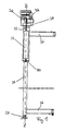
- FIG. 1 shows in a simplified schematic representation of a drive device 20.
- a drive unit 22 is housed in a rotary column 24.
- the rotary column 24 has retaining arms 26 for the attachment of a door, not shown, and is rotatably supported by a bottom bearing 28 on a base, usually a vehicle floor.
- a rotary bearing 38 is shown, via which the rotary column 24 is rotatably mounted about a longitudinal axis ZZ in a bearing 34.
- the drive unit 22 is rotatably connected via a rotary column bearing 30 with the rotary column 24, so that via the rotary column bearing 30, a rotational movement of the rotary column 24 can be effected.
- a guide shaft 32 extends into the bearing 34 and is rotatably connected via a drive unit bearing 36 with this.
- the drive unit bearing 36 may be embodied, for example, as a ball-and-socket joint bearing and serves to receive the torque of the drive unit 22, which in turn is firmly connected to a holding component 40 (cf. FIGS. 4 and 5 ).
- FIG. 2 shows a constructed as a compact drive and arranged in the rotary column 24 drive unit 22, for example, for a passenger door, in the inside a slim, tubular housing 42 in the axial direction one behind the other an electric drive motor 44 and a reduction gear 26, shown as a three-part planetary gear, are arranged.
- the drive motor 44 is followed by a brake 48, which is also housed within the housing 42 and may be designed as a spring-engaging and electromagnetically and mechanically releasable "low-active brake” or as a "high-active brake”.
- the reduction gear 46 is not designed to be self-locking.
- An unrecognizable output element of the drive motor 44 is connected to a likewise not recognizable input element of the reduction gear 46, whose output shaft 54 guide shaft 32 is connected via the rotary column bearing 30 with the rotary column 24.
- the rotary column 24 tapers below the drive unit 22.
- the guide shaft 32 extends from the housing 42 into the bearing 34, the bearing being connected to the support member 40 of the vehicle.
- the torque generated by the drive motor 44 is transmitted via the reduction gear 46 to the transmission output shaft 54.
- only the brake 48 must be solved, after which the manual operation of the passenger door due to the lack of self-locking of the reduction gear 46 is readily possible.
- brake 48 may be provided for locking a short-circuiting device that short-circuits the motor windings of the drive motor 44 for locking.
- Fig. 3 shows a second embodiment of the drive device 20.
- the transmission output shaft 54 acts as a guide shaft 32, projects into the bearing 34 and is rotatably mounted there.
- the housing of the planetary gear 46 is rotatably connected to the rotary column 24. If the drive motor is energized, and the housing of the planetary gear 46 of the drive unit 22 rotates, whereby the rotary column 24 is rotated.
- an outer tube 42 see. Fig. 2
- a torque support guide 66 in Fig. 4
- All electrical and mechanical connection elements e.g. If necessary, a Bowden cable for manual unlocking of the brake, are arranged within the housing 22. Also, when using the drive device 20 in a lifting rotary unit, a sensor may be provided for Huber upset.
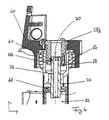
- FIG. 4 illustrates the inventive storage of the drive device 20. Shown is the storage area according to the embodiment of FIG. 2 ,
- the support member 40 serves as a support for the torque of the drive unit 22.
- the bearing 34 is designed as a ball-and-socket joint bearing, and the guide shaft 32 is guided in a two-part ball seat 58 by means of balls 60.
- the guide shaft 32 has spherical seats for the balls 60, which hold them in position.
- corresponding elongated depressions 62 are introduced, which extend in the Z direction.
- the guide shaft 32 is able to perform tumbling movements by these guides.
- the recesses 62 allow the guide shaft 32 to wobble in the Z direction, and the spherical recesses in the guide shaft 32 allow the transmission of torque about the longitudinal axis ZZ.
- the ball seat 58 is arranged centrally in the pivot bearing 64 in the Z direction.
- the rotary column 24 and the guide shaft 32 thus have, so to speak, a common wobble point 70, which is arranged on the longitudinal axis Z-Z.
- the guide shaft 32 is provided with a polygonal geometry which slidably slide in a guide 66 in the Z direction and transmits the torque of the drive unit 22.
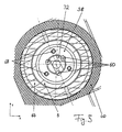
- FIG. 5 shows a cross section through the bearing 34 and illustrates the arrangement of the balls 60. There are screws 68 can be seen, which connect the two ball seats 58 together.
Landscapes
- Power-Operated Mechanisms For Wings (AREA)
- Ship Loading And Unloading (AREA)
Priority Applications (1)
| Application Number | Priority Date | Filing Date | Title |
|---|---|---|---|
| PL08864326T PL2234830T3 (pl) | 2007-12-21 | 2008-12-19 | Urządzenie napędowe do urządzeń do wsiadania/wysiadania |
Applications Claiming Priority (3)
| Application Number | Priority Date | Filing Date | Title |
|---|---|---|---|
| DE202007018082 | 2007-12-21 | ||
| DE202008007585U DE202008007585U1 (de) | 2007-12-21 | 2008-06-04 | Antriebsvorrichtung für Ein-/Ausstiegsvorrichtungen |
| PCT/EP2008/067976 WO2009080733A2 (de) | 2007-12-21 | 2008-12-19 | Antriebsvorrichtung für ein-/ausstiegsvorrichtungen |
Publications (2)
| Publication Number | Publication Date |
|---|---|
| EP2234830A2 EP2234830A2 (de) | 2010-10-06 |
| EP2234830B1 true EP2234830B1 (de) | 2012-05-23 |
Family
ID=40586234
Family Applications (1)
| Application Number | Title | Priority Date | Filing Date |
|---|---|---|---|
| EP08864326A Not-in-force EP2234830B1 (de) | 2007-12-21 | 2008-12-19 | Antriebsvorrichtung für ein-/ausstiegsvorrichtungen |
Country Status (5)
| Country | Link |
|---|---|
| EP (1) | EP2234830B1 (pl) |
| DE (1) | DE202008007585U1 (pl) |
| ES (1) | ES2388553T3 (pl) |
| PL (1) | PL2234830T3 (pl) |
| WO (1) | WO2009080733A2 (pl) |
Families Citing this family (5)
| Publication number | Priority date | Publication date | Assignee | Title |
|---|---|---|---|---|
| DE202009017683U1 (de) * | 2009-12-03 | 2011-04-21 | Gebr. Bode Gmbh & Co. Kg | Antriebsvorrichtung für Ein-/Ausstiegsvorrichtungen mit Sicherheitskupplung |
| CN104011311B (zh) | 2011-10-21 | 2016-07-06 | 盖伯.伯德有限两合公司 | 用于公共客运车辆上下车装置的驱动装置 |
| DE202012100338U1 (de) | 2012-02-01 | 2013-05-02 | Gebr. Bode Gmbh & Co. Kg | Anordnung aus einem Türflügel und einer Antriebsvorrichtung zum Bewegen des Türflügels für ein Personenbeförderungsfahrzeug |
| DE202013102876U1 (de) | 2013-07-01 | 2013-07-16 | Gebr. Bode Gmbh & Co. Kg | Antriebsvorrichtung mit Lager für eine Ein-/Ausstiegsvorrichtung |
| DE202016102025U1 (de) | 2016-04-18 | 2017-07-19 | Gebr. Bode Gmbh & Co. Kg | Anordnung mit Türflügel und Antriebsvorrichtung zum Bewegen des Türflügels für ein Personenbeförderungsfahrzeug |
Family Cites Families (10)
| Publication number | Priority date | Publication date | Assignee | Title |
|---|---|---|---|---|
| DE3332244A1 (de) * | 1983-09-07 | 1985-03-21 | Gebr. Bode & Co GmbH, 3500 Kassel | Antriebsvorrichtung fuer eine drehsaeule, insbesondere zur bewegung von schwenktuerfluegeln an kraftfahrzeugen |
| DE3444134C2 (de) * | 1984-09-12 | 1986-10-09 | Gebr. Bode & Co GmbH, 3500 Kassel | Kugelschraubgetriebe zur Umwandlung einer axialen Bewegung in eine Drehbewegung und umgekehrt für Maschinenbauteile |
| DE3532514C1 (de) * | 1985-09-12 | 1987-04-23 | Bode & Co Geb | Antriebsvorrichtung fuer eine Drehsaeule,insbesondere zur Bewegung von Schwenktuerfluegeln an Kraftfahrzeugen |
| DE29611395U1 (de) * | 1996-07-01 | 1997-11-06 | Gebr. Bode & Co GmbH, 34123 Kassel | Elektromechanische Antriebsvorrichtung für eine Drehsäule zur Bewegung eines Schwenktürflügels an einem Fahrzeug |
| NL1003674C2 (nl) * | 1996-07-24 | 1998-01-28 | Sab Wabco B V | Zwenkschuifdeurstelsel voor een voertuig. |
| DE29905681U1 (de) | 1999-03-27 | 2000-08-10 | Gebr. Bode GmbH & Co. KG, 34123 Kassel | Schwenkschiebetür für Fahrzeuge, insbesondere Fahrzeuge des öffentlichen Personennahverkehrs |
| DE10158094A1 (de) | 2001-11-27 | 2003-07-24 | Bode Gmbh & Co Kg | Schwenkschiebetür für Fahrzeuge, insbesondere Fahrgasttür für Fahrzeuge des öffentlichen Personennahverkehrs |
| GB2403265B (en) * | 2003-06-25 | 2005-12-28 | Manganese Bronze Components Lt | Sliding plug doors |
| DE20316764U1 (de) | 2003-10-31 | 2005-03-17 | Bode Gmbh & Co Kg | Schwenkschiebetür für Fahrzeuge, insbesondere Fahrgasttür für Fahrzeuge des öffentlichen Personennahverkehrs |
| DE202005015169U1 (de) * | 2005-09-27 | 2007-02-15 | Gebr. Bode Gmbh & Co. Kg | Schwenkschiebetür für Fahrzeuge, insbesondere Fahrgasttür für Fahrzeuge des öffentlichen Personennahverkehrs |
-
2008
- 2008-06-04 DE DE202008007585U patent/DE202008007585U1/de not_active Expired - Lifetime
- 2008-12-19 PL PL08864326T patent/PL2234830T3/pl unknown
- 2008-12-19 ES ES08864326T patent/ES2388553T3/es active Active
- 2008-12-19 WO PCT/EP2008/067976 patent/WO2009080733A2/de not_active Ceased
- 2008-12-19 EP EP08864326A patent/EP2234830B1/de not_active Not-in-force
Also Published As
| Publication number | Publication date |
|---|---|
| DE202008007585U1 (de) | 2009-04-30 |
| PL2234830T3 (pl) | 2012-10-31 |
| WO2009080733A2 (de) | 2009-07-02 |
| ES2388553T3 (es) | 2012-10-16 |
| WO2009080733A3 (de) | 2009-08-27 |
| EP2234830A2 (de) | 2010-10-06 |
Similar Documents
| Publication | Publication Date | Title |
|---|---|---|
| EP2238307B1 (de) | Drehwegerfassungsvorrichtung | |
| EP2507461B1 (de) | Antriebsvorrichtung für ein-/ausstiegsvorrichtungen mit sicherheitskupplung | |
| EP2220317B1 (de) | Elektrisch angetriebene drehsäule für fahrzeuge des öffentlichen personenverkehrs | |
| EP2769041B1 (de) | Antriebsvorrichtung für ein- und ausstiegseinrichtungen von fahrzeugen des öffentlichen personenverkehrs | |
| DE102015104111A1 (de) | Antriebsmechanismus mit Doppelschneckengetriebe | |
| DE102017204914A1 (de) | Kraft-Schwenktür-Betätigungsglied mit gelenkigem Verbindungsmechanismus | |
| DE102017205605A1 (de) | Kraft-Schwenktür-Betätigungsglied mit integriertem Tür-Kontrollmechanismus | |
| EP2326783B1 (de) | Antriebsvorrichtung für ein-/ausstiegsvorrichtungen mit kupplung | |
| EP3899179B1 (de) | Aufstellvorrichtung für ein kraftfahrzeugtürelement | |
| EP2078129B1 (de) | Antriebsvorrichtung für ein- und ausstiegseinrichtungen | |
| EP2234830A2 (de) | Antriebsvorrichtung für ein-/ausstiegsvorrichtungen | |
| EP3915829A1 (de) | Fahrzeugsitzbeschlag und fahrzeugsitz | |
| DE102017101997A1 (de) | Elektrisch entriegelbares Türschloss mit Zuziehfunktion | |
| WO2009092753A1 (de) | Antriebsvorrichtung mit zweifacher drehmomentnutzung | |
| DE102009004498B4 (de) | Türanordnung mit einer Schließfolgeregelung | |
| EP2790992B1 (de) | Antriebseinheit | |
| EP1570148B1 (de) | Kombinierte antriebseinheit für wenigstens ein aggregat und ein türschloss in einer kraftfahrzeugtür | |
| WO2017182475A1 (de) | Anordnung mit türflügel und antriebsvorrichtung zum bewegen des türflügels für ein personenbeförderungsfahrzeug | |
| EP3033257B1 (de) | Verfahren und vorrichtung zur verriegelung einer schienenfahrzeugschiebetüre | |
| DE102012105530B4 (de) | Verriegelungsvorrichtung | |
| DE102019127875A1 (de) | Schwenksystem für ein Fahrzeug sowie Linearaktuator zum Öffnen und Schließen einer Fahrzeugtür | |
| EP1915267A1 (de) | Schiebetür | |
| DE102019114513A1 (de) | Schrankensystem | |
| EP3858659A1 (de) | Sitzkonsole für ein fahrzeug: verfahren zur bedienung einer schwenkbaren sitzkonsole eines fahrzeugs; verfahren zum aus- oder nachrüsten eines fahrzeugsitzes eines fahrzeugs mit einer schwenkfunktion | |
| DE19723174A1 (de) | Elektrisch betriebener Sicherheitsverschluß mit zusätzlichem Betätigungsantrieb für Türen und Fenster |
Legal Events
| Date | Code | Title | Description |
|---|---|---|---|
| PUAI | Public reference made under article 153(3) epc to a published international application that has entered the european phase |
Free format text: ORIGINAL CODE: 0009012 |
|
| 17P | Request for examination filed |
Effective date: 20100721 |
|
| AK | Designated contracting states |
Kind code of ref document: A2 Designated state(s): AT BE BG CH CY CZ DE DK EE ES FI FR GB GR HR HU IE IS IT LI LT LU LV MC MT NL NO PL PT RO SE SI SK TR |
|
| AX | Request for extension of the european patent |
Extension state: AL BA MK RS |
|
| DAX | Request for extension of the european patent (deleted) | ||
| REG | Reference to a national code |
Ref country code: DE Ref legal event code: R079 Ref document number: 502008007276 Country of ref document: DE Free format text: PREVIOUS MAIN CLASS: B60J0005060000 Ipc: E05F0015120000 |
|
| RIC1 | Information provided on ipc code assigned before grant |
Ipc: E05F 15/12 20060101AFI20111222BHEP Ipc: E05D 15/10 20060101ALI20111222BHEP Ipc: B60J 5/06 20060101ALI20111222BHEP |
|
| GRAP | Despatch of communication of intention to grant a patent |
Free format text: ORIGINAL CODE: EPIDOSNIGR1 |
|
| GRAS | Grant fee paid |
Free format text: ORIGINAL CODE: EPIDOSNIGR3 |
|
| GRAA | (expected) grant |
Free format text: ORIGINAL CODE: 0009210 |
|
| AK | Designated contracting states |
Kind code of ref document: B1 Designated state(s): AT BE BG CH CY CZ DE DK EE ES FI FR GB GR HR HU IE IS IT LI LT LU LV MC MT NL NO PL PT RO SE SI SK TR |
|
| REG | Reference to a national code |
Ref country code: GB Ref legal event code: FG4D Free format text: NOT ENGLISH |
|
| REG | Reference to a national code |
Ref country code: CH Ref legal event code: EP |
|
| REG | Reference to a national code |
Ref country code: AT Ref legal event code: REF Ref document number: 559199 Country of ref document: AT Kind code of ref document: T Effective date: 20120615 |
|
| REG | Reference to a national code |
Ref country code: IE Ref legal event code: FG4D Free format text: LANGUAGE OF EP DOCUMENT: GERMAN |
|
| REG | Reference to a national code |
Ref country code: DE Ref legal event code: R096 Ref document number: 502008007276 Country of ref document: DE Effective date: 20120719 |
|
| REG | Reference to a national code |
Ref country code: NL Ref legal event code: T3 |
|
| REG | Reference to a national code |
Ref country code: ES Ref legal event code: FG2A Ref document number: 2388553 Country of ref document: ES Kind code of ref document: T3 Effective date: 20121016 |
|
| REG | Reference to a national code |
Ref country code: LT Ref legal event code: MG4D Effective date: 20120523 |
|
| PG25 | Lapsed in a contracting state [announced via postgrant information from national office to epo] |
Ref country code: CY Free format text: LAPSE BECAUSE OF FAILURE TO SUBMIT A TRANSLATION OF THE DESCRIPTION OR TO PAY THE FEE WITHIN THE PRESCRIBED TIME-LIMIT Effective date: 20120523 Ref country code: LT Free format text: LAPSE BECAUSE OF FAILURE TO SUBMIT A TRANSLATION OF THE DESCRIPTION OR TO PAY THE FEE WITHIN THE PRESCRIBED TIME-LIMIT Effective date: 20120523 Ref country code: NO Free format text: LAPSE BECAUSE OF FAILURE TO SUBMIT A TRANSLATION OF THE DESCRIPTION OR TO PAY THE FEE WITHIN THE PRESCRIBED TIME-LIMIT Effective date: 20120823 Ref country code: SE Free format text: LAPSE BECAUSE OF FAILURE TO SUBMIT A TRANSLATION OF THE DESCRIPTION OR TO PAY THE FEE WITHIN THE PRESCRIBED TIME-LIMIT Effective date: 20120523 Ref country code: IS Free format text: LAPSE BECAUSE OF FAILURE TO SUBMIT A TRANSLATION OF THE DESCRIPTION OR TO PAY THE FEE WITHIN THE PRESCRIBED TIME-LIMIT Effective date: 20120923 Ref country code: FI Free format text: LAPSE BECAUSE OF FAILURE TO SUBMIT A TRANSLATION OF THE DESCRIPTION OR TO PAY THE FEE WITHIN THE PRESCRIBED TIME-LIMIT Effective date: 20120523 |
|
| REG | Reference to a national code |
Ref country code: PL Ref legal event code: T3 |
|
| PG25 | Lapsed in a contracting state [announced via postgrant information from national office to epo] |
Ref country code: HR Free format text: LAPSE BECAUSE OF FAILURE TO SUBMIT A TRANSLATION OF THE DESCRIPTION OR TO PAY THE FEE WITHIN THE PRESCRIBED TIME-LIMIT Effective date: 20120523 Ref country code: PT Free format text: LAPSE BECAUSE OF FAILURE TO SUBMIT A TRANSLATION OF THE DESCRIPTION OR TO PAY THE FEE WITHIN THE PRESCRIBED TIME-LIMIT Effective date: 20120924 Ref country code: SI Free format text: LAPSE BECAUSE OF FAILURE TO SUBMIT A TRANSLATION OF THE DESCRIPTION OR TO PAY THE FEE WITHIN THE PRESCRIBED TIME-LIMIT Effective date: 20120523 Ref country code: GR Free format text: LAPSE BECAUSE OF FAILURE TO SUBMIT A TRANSLATION OF THE DESCRIPTION OR TO PAY THE FEE WITHIN THE PRESCRIBED TIME-LIMIT Effective date: 20120824 Ref country code: LV Free format text: LAPSE BECAUSE OF FAILURE TO SUBMIT A TRANSLATION OF THE DESCRIPTION OR TO PAY THE FEE WITHIN THE PRESCRIBED TIME-LIMIT Effective date: 20120523 |
|
| PG25 | Lapsed in a contracting state [announced via postgrant information from national office to epo] |
Ref country code: RO Free format text: LAPSE BECAUSE OF FAILURE TO SUBMIT A TRANSLATION OF THE DESCRIPTION OR TO PAY THE FEE WITHIN THE PRESCRIBED TIME-LIMIT Effective date: 20120523 Ref country code: SK Free format text: LAPSE BECAUSE OF FAILURE TO SUBMIT A TRANSLATION OF THE DESCRIPTION OR TO PAY THE FEE WITHIN THE PRESCRIBED TIME-LIMIT Effective date: 20120523 Ref country code: EE Free format text: LAPSE BECAUSE OF FAILURE TO SUBMIT A TRANSLATION OF THE DESCRIPTION OR TO PAY THE FEE WITHIN THE PRESCRIBED TIME-LIMIT Effective date: 20120523 Ref country code: DK Free format text: LAPSE BECAUSE OF FAILURE TO SUBMIT A TRANSLATION OF THE DESCRIPTION OR TO PAY THE FEE WITHIN THE PRESCRIBED TIME-LIMIT Effective date: 20120523 |
|
| PGFP | Annual fee paid to national office [announced via postgrant information from national office to epo] |
Ref country code: TR Payment date: 20121213 Year of fee payment: 5 |
|
| PLBE | No opposition filed within time limit |
Free format text: ORIGINAL CODE: 0009261 |
|
| STAA | Information on the status of an ep patent application or granted ep patent |
Free format text: STATUS: NO OPPOSITION FILED WITHIN TIME LIMIT |
|
| 26N | No opposition filed |
Effective date: 20130226 |
|
| REG | Reference to a national code |
Ref country code: DE Ref legal event code: R097 Ref document number: 502008007276 Country of ref document: DE Effective date: 20130226 |
|
| PG25 | Lapsed in a contracting state [announced via postgrant information from national office to epo] |
Ref country code: MC Free format text: LAPSE BECAUSE OF NON-PAYMENT OF DUE FEES Effective date: 20121231 Ref country code: BG Free format text: LAPSE BECAUSE OF FAILURE TO SUBMIT A TRANSLATION OF THE DESCRIPTION OR TO PAY THE FEE WITHIN THE PRESCRIBED TIME-LIMIT Effective date: 20120823 |
|
| REG | Reference to a national code |
Ref country code: CH Ref legal event code: PL |
|
| REG | Reference to a national code |
Ref country code: IE Ref legal event code: MM4A |
|
| PG25 | Lapsed in a contracting state [announced via postgrant information from national office to epo] |
Ref country code: CH Free format text: LAPSE BECAUSE OF NON-PAYMENT OF DUE FEES Effective date: 20121231 Ref country code: LI Free format text: LAPSE BECAUSE OF NON-PAYMENT OF DUE FEES Effective date: 20121231 Ref country code: IE Free format text: LAPSE BECAUSE OF NON-PAYMENT OF DUE FEES Effective date: 20121219 |
|
| PG25 | Lapsed in a contracting state [announced via postgrant information from national office to epo] |
Ref country code: MT Free format text: LAPSE BECAUSE OF FAILURE TO SUBMIT A TRANSLATION OF THE DESCRIPTION OR TO PAY THE FEE WITHIN THE PRESCRIBED TIME-LIMIT Effective date: 20120523 |
|
| PGFP | Annual fee paid to national office [announced via postgrant information from national office to epo] |
Ref country code: CZ Payment date: 20131210 Year of fee payment: 6 Ref country code: GB Payment date: 20131217 Year of fee payment: 6 |
|
| PGFP | Annual fee paid to national office [announced via postgrant information from national office to epo] |
Ref country code: NL Payment date: 20131216 Year of fee payment: 6 Ref country code: PL Payment date: 20131210 Year of fee payment: 6 Ref country code: FR Payment date: 20131213 Year of fee payment: 6 Ref country code: IT Payment date: 20131217 Year of fee payment: 6 Ref country code: ES Payment date: 20131216 Year of fee payment: 6 |
|
| PGFP | Annual fee paid to national office [announced via postgrant information from national office to epo] |
Ref country code: BE Payment date: 20131216 Year of fee payment: 6 |
|
| PGFP | Annual fee paid to national office [announced via postgrant information from national office to epo] |
Ref country code: DE Payment date: 20131217 Year of fee payment: 6 |
|
| PG25 | Lapsed in a contracting state [announced via postgrant information from national office to epo] |
Ref country code: LU Free format text: LAPSE BECAUSE OF NON-PAYMENT OF DUE FEES Effective date: 20121219 |
|
| PG25 | Lapsed in a contracting state [announced via postgrant information from national office to epo] |
Ref country code: HU Free format text: LAPSE BECAUSE OF FAILURE TO SUBMIT A TRANSLATION OF THE DESCRIPTION OR TO PAY THE FEE WITHIN THE PRESCRIBED TIME-LIMIT Effective date: 20081219 |
|
| REG | Reference to a national code |
Ref country code: AT Ref legal event code: MM01 Ref document number: 559199 Country of ref document: AT Kind code of ref document: T Effective date: 20131219 |
|
| PG25 | Lapsed in a contracting state [announced via postgrant information from national office to epo] |
Ref country code: AT Free format text: LAPSE BECAUSE OF NON-PAYMENT OF DUE FEES Effective date: 20131219 |
|
| PG25 | Lapsed in a contracting state [announced via postgrant information from national office to epo] |
Ref country code: BE Free format text: LAPSE BECAUSE OF NON-PAYMENT OF DUE FEES Effective date: 20141231 |
|
| REG | Reference to a national code |
Ref country code: DE Ref legal event code: R119 Ref document number: 502008007276 Country of ref document: DE |
|
| REG | Reference to a national code |
Ref country code: NL Ref legal event code: V1 Effective date: 20150701 |
|
| REG | Reference to a national code |
Ref country code: NL Ref legal event code: V1 Effective date: 20150701 |
|
| PG25 | Lapsed in a contracting state [announced via postgrant information from national office to epo] |
Ref country code: CZ Free format text: LAPSE BECAUSE OF NON-PAYMENT OF DUE FEES Effective date: 20141219 |
|
| GBPC | Gb: european patent ceased through non-payment of renewal fee |
Effective date: 20141219 |
|
| REG | Reference to a national code |
Ref country code: FR Ref legal event code: ST Effective date: 20150831 |
|
| PG25 | Lapsed in a contracting state [announced via postgrant information from national office to epo] |
Ref country code: NL Free format text: LAPSE BECAUSE OF NON-PAYMENT OF DUE FEES Effective date: 20150701 |
|
| PG25 | Lapsed in a contracting state [announced via postgrant information from national office to epo] |
Ref country code: DE Free format text: LAPSE BECAUSE OF NON-PAYMENT OF DUE FEES Effective date: 20150701 Ref country code: GB Free format text: LAPSE BECAUSE OF NON-PAYMENT OF DUE FEES Effective date: 20141219 |
|
| PG25 | Lapsed in a contracting state [announced via postgrant information from national office to epo] |
Ref country code: FR Free format text: LAPSE BECAUSE OF NON-PAYMENT OF DUE FEES Effective date: 20141231 |
|
| PG25 | Lapsed in a contracting state [announced via postgrant information from national office to epo] |
Ref country code: IT Free format text: LAPSE BECAUSE OF NON-PAYMENT OF DUE FEES Effective date: 20141219 |
|
| REG | Reference to a national code |
Ref country code: ES Ref legal event code: FD2A Effective date: 20160128 |
|
| PG25 | Lapsed in a contracting state [announced via postgrant information from national office to epo] |
Ref country code: ES Free format text: LAPSE BECAUSE OF NON-PAYMENT OF DUE FEES Effective date: 20141220 |
|
| PG25 | Lapsed in a contracting state [announced via postgrant information from national office to epo] |
Ref country code: PL Free format text: LAPSE BECAUSE OF NON-PAYMENT OF DUE FEES Effective date: 20141219 |
|
| PG25 | Lapsed in a contracting state [announced via postgrant information from national office to epo] |
Ref country code: TR Free format text: LAPSE BECAUSE OF NON-PAYMENT OF DUE FEES Effective date: 20141219 |