EP2234218A2 - Elektrische Steckverbindung - Google Patents
Elektrische Steckverbindung Download PDFInfo
- Publication number
- EP2234218A2 EP2234218A2 EP10003103A EP10003103A EP2234218A2 EP 2234218 A2 EP2234218 A2 EP 2234218A2 EP 10003103 A EP10003103 A EP 10003103A EP 10003103 A EP10003103 A EP 10003103A EP 2234218 A2 EP2234218 A2 EP 2234218A2
- Authority
- EP
- European Patent Office
- Prior art keywords
- plug
- housing
- spring
- connector
- mating connector
- Prior art date
- Legal status (The legal status is an assumption and is not a legal conclusion. Google has not performed a legal analysis and makes no representation as to the accuracy of the status listed.)
- Granted
Links
Images


Classifications
-
- H—ELECTRICITY
- H01—ELECTRIC ELEMENTS
- H01R—ELECTRICALLY-CONDUCTIVE CONNECTIONS; STRUCTURAL ASSOCIATIONS OF A PLURALITY OF MUTUALLY-INSULATED ELECTRICAL CONNECTING ELEMENTS; COUPLING DEVICES; CURRENT COLLECTORS
- H01R13/00—Details of coupling devices of the kinds covered by groups H01R12/70 or H01R24/00 - H01R33/00
- H01R13/62—Means for facilitating engagement or disengagement of coupling parts or for holding them in engagement
- H01R13/627—Snap or like fastening
- H01R13/6277—Snap or like fastening comprising annular latching means, e.g. ring snapping in an annular groove
-
- H—ELECTRICITY
- H01—ELECTRIC ELEMENTS
- H01R—ELECTRICALLY-CONDUCTIVE CONNECTIONS; STRUCTURAL ASSOCIATIONS OF A PLURALITY OF MUTUALLY-INSULATED ELECTRICAL CONNECTING ELEMENTS; COUPLING DEVICES; CURRENT COLLECTORS
- H01R13/00—Details of coupling devices of the kinds covered by groups H01R12/70 or H01R24/00 - H01R33/00
- H01R13/62—Means for facilitating engagement or disengagement of coupling parts or for holding them in engagement
- H01R13/629—Additional means for facilitating engagement or disengagement of coupling parts, e.g. aligning or guiding means, levers, gas pressure electrical locking indicators, manufacturing tolerances
- H01R13/633—Additional means for facilitating engagement or disengagement of coupling parts, e.g. aligning or guiding means, levers, gas pressure electrical locking indicators, manufacturing tolerances for disengagement only
- H01R13/635—Additional means for facilitating engagement or disengagement of coupling parts, e.g. aligning or guiding means, levers, gas pressure electrical locking indicators, manufacturing tolerances for disengagement only by mechanical pressure, e.g. spring force
Definitions
- the invention relates to an electrical plug connection, which comprises a plug and a mating connector, each having a housing, wherein a force acting between the housings spring element for locking the plug is provided with the mating connector.
- the GB 2 338 124 B discloses an electrical connector with a plug and a mating connector, each inserted in a housing.
- a front panel of the housing of the mating connector is provided with two diametrically opposed resilient clip arms and has a circumferential collar corresponding to an outside edge at the free end of the housing of the connector.
- the edge of the housing of the plug in the collar of the front panel of the housing of the mating connector and the two latching arms engage behind associated latching projections which are formed on the inside at the free end of the housing of the plug.
- the plug protrudes beyond the free end of its housing, which prevents it from being damaged.
- the spring element is designed as a housing associated snap spring, which locks the plug with the associated mating connector in its first stable position and the release relative to the plug connection and the associated transition into its second stable position the plug axially displaced to the mating connector.
- the snap spring works on the so-called crack-frog principle and takes due to their familiar to those skilled shaping two stable positions. In its first stable position, the snap spring locks the plug to the associated one Mating connector and causes due to their spring action increased resistance to disconnection of the connector. If the housing of the plug in the pulling direction or a direction perpendicular thereto loaded, then the snap spring goes into its second stable position and moves the plug relative to the mating connector in the axial direction, the connector, although not completely, but then partially solved is to overcome a portion of the frictional forces acting between the fully inserted into the mating connector plug. Because of this principle of action, the plug connection according to the invention issausfard, ie upon actuation of the snap spring, the plug is separated from the mating plugsausuite filedd by the action of the spring and ejected.
- the snap spring is formed rondenförmig, has a plurality, preferably four to eight, radially aligned spring arms and in its center an opening.
- the spring arms form an integral part of the snap spring and are shaped in their longitudinal course so that they represent individual snap springs. Through the central opening of the snap spring, the connector is made.
- one of the housing is provided with a snap-spring fixing collar and the other housing with an undercut for engagement of the free ends of the spring arms in the locked state of the connector.
- the collar holds the snap spring force and / or positive fit.
- a press connection between the usually made of a spring steel snap spring and made of a plastic collar is realized.
- the snap spring produces an effective locking connection with the other housing, engage the free ends of the spring arms in the locked state of the connector in a corresponding undercut.
- the snap spring can take their first and second stable position in which it is more or less cup-shaped arched expediently fixes the Bund the snap spring at the edge in the axial direction spaced from the associated housing.
- the collar either engages in the opening of the snap spring or fixes the snap spring on its outer periphery and the undercut is formed either for the radially outwardly or radially inwardly acting spring arms.
- the snap spring may be held either at its peripheral periphery or in its central opening on the housing of the plug or the housing of the mating connector. If the snap spring is held in its opening, then the spring arms can point with their free ends to the outside and run in a star shape in the direction of the center. If the snap spring is attached to its outer circumference, then the free ends point towards the center. Of course, there are preferably each V-shaped cuts between the spring arms.
- annular bead is formed on the housing having the undercut, which actuates the free ends of the spring arms for receiving the first stable position of the snap spring when joining the connector, in which the plug is locked to the mating connector.
- the federal government causes overbending the snap spring.
- the free ends of the spring arms of the snap spring in the manufacture of the connector no excessive wear of the housing, in particular abrasion of plastic by the metallic spring arms cause, advantageously the undercut is formed in a holding basket inserted into the housing. Accordingly, it is possible to form the holding basket, for example, a more abrasion-resistant material than the rest of the housing, in particular, the holding basket can be made for example of a metallic material.
- the plug In order to allow a slight relative movement between the plug and the housing, the plug is fixed by a tolerance compensation in the housing.
- the tolerance compensation can be, for example, a simple franking in the housing, which forms a plug holding collar in the housing and allows compensation of tolerance-related positional differences between the plug and the mating connector.
- the plug protrudes with its free end out of his, in particular bell-shaped, housing out. Accordingly, the plug is first to be inserted into the mating connector and then the locking of the two housings takes place by the snap spring.
- the mating connector is mounted in a building wall and the plug is part of a device, via the connector, for example, the connection of a telephone or a computer to a corresponding network. So that the wall-mounted housing is easy to clean when needed, the housing of the mating connector in the region of the parting plane of the connector plate-shaped.
- the mating connector is at the end of a front panel of its housing. Accordingly, the mating connector is not on the front panel of the housing.
- the snap spring and / or a cable connected to the plug and / or the holding basket with plastic, in particular of the respective housing, encapsulated can thus be made for example by encapsulation during the manufacture of the housing.
- the plug, the snap spring and / or the holding basket can be inserted as inserts in an injection mold.
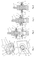
- the plug connection comprises a plug 2 inserted in a bell-shaped housing 1 and a mating plug 5 likewise received in a housing 3 behind a front panel 4.
- the plug 2 is connected to a cable 6 injected into the housing 1.
- Between the housings 1, 3 designed as a snap spring 7 spring element 8 is provided for locking the plug 2 with the mating connector 5.
- the snap spring 7 locks in its first stable position the plug 2 with the mating connector 5 connected thereto and shifts the connector 2 relative to the mating connector 5 when releasing the connector and the associated transition into its second stable position.
- the ronde-shaped snap spring 7 has radially aligned spring arms 9 and in its center an opening 10 for the connector.
- a collar 11 is formed, which fixes the snap spring 7 at its outer periphery.
- the snap spring 7 is curved in its second stable position, in the disconnected state of the connector, convex in a direction opposite to the cable 6 direction and the spring arms 9 are directed radially inward. Pointing in the direction of the center, the free ends of the spring arms 9 form the opening 10, which projects through the plug 2 with its free end 12.
- a holding basket 13 is inserted, which corresponds to the free ends of the spring arms 9 oriented in the direction of the snap spring 7 annular bead 14 and in the transition region to the bead 14 has an undercut 15.
- the holding basket 13 is anchored by means of a peripheral edge 16 in the front panel 4.
- the plug-in connector 2 is first brought into engagement with the mating connector 5 and the metallic spring arms 9 come with their free ends on the bead 14 of the metallic holding basket 13 to support.
- the spring arms 9 of the snap spring 7 are deformed in the direction of the housing 1 of the plug 2 until the housing 1 of the plug 2 rests against the front panel 4 of the housing 3 of the mating connector 5.
- the snap spring 7 in its first stable, especially metastable, position in which the free ends of their spring arms 9 engage in the circumferential, annular undercut 15 of the holding basket 13 and thus lock the plug 2 against the mating connector 5.
- the housing 2 of the plug In order to create the clearance required for an overbending of the spring arms 9 by the bead 14 of the holding basket 13, the housing 2 of the plug 1, starting from a plane in which the snap spring 7 is held circumferentially, concavely arched. If the connector is to be disconnected, an attack on the housing 1 of the plug 2 and its load in a corresponding direction, which is not rectilinearly directed to the housing 3 of the mating connector 5, whereby the snap spring 7 after the so-called crack-frog principle from her first stable position in the second stable position changes while the plug 2 moves axially relative to the mating connector 5.
- the collar 11 is formed for attachment of the snap spring 7 at its outer periphery on the front panel 4 of the housing 3 of the mating connector 5.
- the snap spring 7 is convex in the disconnected state of the connector in a direction opposite to the mating connector 5 and is in its second stable position, wherein the spring arms 9 are directed radially inward and form an opening 10 for the connector in the center of the snap spring 7.
- the mating connector 5 is located with its free end 17 on the side facing away from the snap spring 7 side of the front panel 4 on the front panel 4, in which a franking 18 behind the Snap spring 7 for the free ends of the spring arms 9 is embedded in the first stable position.
- the holding basket 13 is held over its outer edge 16 in the housing 1 of the plug 2 and its extending in the direction of the free end of the plug 2 bead 14 is by a coaxial with the outer periphery of the housing 1 of the plug 2 aligned ring 23, the component of the housing 2 is centered.
- the plug 2 is first brought into engagement with the mating connector 5, wherein the spring arms 9 come to rest with their free ends on the bead 14 of the holding basket 13.
- the spring arms 9 of the snap spring 7 are deformed in the direction of the housing 1 of the mating connector 2 until the housing 1 of the plug 2 rests against the front panel 4 of the housing 3 of the mating connector 5.
- the collar 11 engages for fastening the snap spring 7 in the opening 10 and is thus formed around the plug 2 around in the center of the housing 1 of the plug.
- the spring arms 9 are directed radially outward, facing the free end 12 of the plug 2, and the snap spring 7 is concave in the separated state of the connector in its second stable position.
- the collar 11 holds the snap spring 7 so spaced from the associated housing 1, that the free ends of the spring arms 9 can be bent to take the first stable position in the direction of the cable 6 pointing.
- the holding basket 13 is held over its outer edge 16 in the housing 3 of the mating connector 5, wherein its pointing in the direction of the plug 2 bead 14 by a coaxially aligned to the outer periphery of the snap spring 7 ring 19, the Part of the housing 3 is centered.
- the holding basket 13 of the concave curvature of the front panel 4 of the housing 3 of the mating connector 5 is inserted into the front panel 4 following.
- the connector is made in which the plug 2 is brought into engagement with the mating connector 5. From a certain joining position, the spring arms are 9 with their free ends on the holding basket 13 and move in a continued insertion movement in the direction of the bead 14, where they engage in the undercut 15. Subsequently, the spring arms 9 are bent over so that the snap spring 7 assumes its first stable position in which the plug 2 is locked against the mating connector 5. The separation of the plug connection is made as already described.
- the collar 11 for attaching the snap spring 7, which engages in the opening 10, the housing 3 of the mating connector 5 assigned and formed around the mating connector 5 in the center of the housing 3.
- the spring arms 9 have with their free ends radially outward, and are bent in a direction opposite to the front panel 4 direction such that the snap spring 7 is concave in the separated state of the connector in its second stable position.
- the collar 11 holds the snap spring 7 so spaced to the front panel 4, that the free ends of the spring arms 9 are to turn to assume the first stable position in the direction of the mating connector 5 facing.
- the holding basket 13 is held in its outer edge 16 in the housing 1 of the plug 2, wherein its bead 14 pointing in the opposite direction to the cable 6 is formed by a ring 20 which is coaxial with the outer circumference of the corresponding housing 1 and forms part of the housing 1. is centered. In the further course of the holding basket 13 is adapted to the concave curvature of the housing 1 of the plug 2 and flush with the housing 1.
- the plug 2 is fixed in the housing 1 via a tolerance compensation 21 in the form of a clearing 22.
- the clearance 22 allows a slight change in position of the plug 2 and allows compensation for inaccuracies between the plug 2 and the mating connector. 5
- the spring arms When making the connector of the plug 2 is added to the mating connector 5 and in a certain position, the spring arms are 9 with their free ends on the holding basket 13. Upon further joining, the free ends of the spring arms 9 move in the direction of the bead 14, where they engage in the annular undercut 15. Subsequently, the spring arms 9 are bent over so that the snap spring 7 assumes its first stable position in which the plug 2 is locked against the mating connector 5. The separation of the connector is, as already explained, made.
Landscapes
- Details Of Connecting Devices For Male And Female Coupling (AREA)
Abstract
Description
- Die Erfindung bezieht sich auf eine elektrische Steckverbindung, die einen Stecker und einen Gegenstecker mit jeweils einem Gehäuse umfasst, wobei ein zwischen den Gehäusen wirkendes Federelement zur Verriegelung des Steckers mit dem Gegenstecker vorgesehen ist.
- Die
GB 2 338 124 B - Aus der
EP 863 576 A1 - Das Gleiche gilt für die elektrische Steckverbindung gemäß
JP 09/306594 A - Es ist Aufgabe der Erfindung, eine Steckverbindung der eingangs genannten Art zu schaffen, die sowohl einfach und sicher zu fügen als auch zu trennen ist und dennoch einen erhöhten Widerstand bei der Trennung aufweist.
- Erfindungsgemäß wird die Aufgabe dadurch gelöst, das Federelement als einem der Gehäuse zugeordnete Schnappfeder ausgebildet ist, die in ihrer ersten stabilen Lage den Stecker mit dem damit verbunden Gegenstecker verriegelt und beim Lösen der Steckverbindung und dem damit verbundenen Übergang in ihre zweite stabile Lage den Stecker relativ zu dem Gegenstecker axial verschiebt.
- Die Schnappfeder arbeitet nach dem so genannten Knackfrosch-Prinzip und nimmt aufgrund ihrer dem Fachmann geläufigen Formgebung zwei stabile Lagen ein. In ihrer ersten stabilen Lage verriegelt die Schnappfeder den Stecker mit dem damit verbunden Gegenstecker und bewirkt aufgrund ihrer Federwirkung einen erhöhten Widerstand gegen ein Trennen der Steckverbindung. Wird das Gehäuse des Steckers in Zugrichtung oder eine dazu senkrecht ausgerichtete Richtung belastet, dann geht die Schnappfeder in ihre zweite stabile Lage über und verschiebt den Stecker relativ zu dem Gegenstecker in axialer Richtung, wobei die Steckverbindung, wenn auch nicht vollständig, dann doch teilweise gelöst wird, um einen Teil der zwischen dem vollständig in den Gegenstecker eingesetzten Stecker wirkenden Reibungskräfte zu überwinden. Aufgrund dieses Wirkprinzips ist die erfindungsgemäße Steckverbindung selbstauswerfend, d.h. bei Betätigung der Schnappfeder wird der Stecker vom Gegenstecker selbstauswerfend durch die Aktion der Feder getrennt und ausgeworfen.
- Bevorzugt ist die Schnappfeder rondenförmig ausgebildet, weist mehrere, vorzugsweise vier bis acht, radial ausgerichtete Federarme und in ihrem Zentrum eine Öffnung auf. Die Federarme bilden einen wesentlichen Bestandteil der Schnappfeder und sind in ihrem Längsverlauf derart geformt, dass sie einzelne Schnappfedern darstellen. Durch die zentrale Öffnung der Schnappfeder wird die Steckverbindung hergestellt.
- In Ausgestaltung ist eines der Gehäuse mit einem die Schnappfeder fixierenden Bund und das andere Gehäuse mit einem Hinterschnitt zum Eingriff der freien Enden der Federarme im verriegelten Zustand der Steckverbindung versehen. Der Bund haltert die Schnappfeder kraft- und/oder formschlüssig. Im einfachsten Fall ist eine Pressverbindung zwischen der in der Regel aus einem Federstahl gefertigten Schnappfeder und dem aus einem Kunststoff bestehenden Bund realisiert. Damit die Schnappfeder eine wirksame verriegelnde Verbindung mit dem jeweils anderen Gehäuse herstellt, greifen die freien Enden der Federarme im verriegelten Zustand der Steckverbindung in einen entsprechenden Hinterschnitt ein.
- Damit die Schnappfeder ihre erste und zweite stabile Lage einnehmen kann, in der sie jeweils mehr oder weniger tellerförmig gewölbt ist, fixiert zweckmäßigerweise der Bund die Schnappfeder randseitig in axialer Richtung beabstandet zu dem zugeordneten Gehäuse.
- Nach einer Weiterbildung greift der Bund entweder in die Öffnung der Schnappfeder ein oder fixiert die Schnappfeder an ihrem äußeren Umfang und der Hinterschnitt ist entweder für die radial nach außen oder die radial nach innen wirkenden Federarme ausgebildet. Insgesamt gibt es demnach vier Möglichkeiten die Schnappfeder auszubilden und anzuordnen. Die Schnappfeder kann entweder an ihren peripheren Umfang oder in ihrer zentralen Öffnung an dem Gehäuse des Steckers oder dem Gehäuse des Gegensteckers gehalten sein. Ist die Schnappfeder in ihrer Öffnung gehalten, dann können die Federarme mit ihren freien Enden nach außen weisen und laufen sternförmig in Richtung des Zentrums. Ist die Schnappfeder an ihrem äußeren Umfang befestigt, dann weisen die freien Enden in Richtung des Zentrums. Selbstverständlich befinden sich zwischen den Federarmen jeweils vorzugsweise V-förmige Einschnitte.
- Zweckmäßigerweise ist an dem den Hinterschnitt aufweisenden Gehäuse ein ringförmiger Wulst ausgebildet, der beim Fügen der Steckverbindung die freien Enden der Federarme zur Einnahme der ersten stabilen Lage der Schnappfeder betätigt, in der der Stecker mit dem Gegenstecker verriegelt ist. Der Bund bewirkt ein Überbiegen der Schnappfeder.
- Damit die freien Enden der Federarme der Schnappfeder beim Herstellen der Steckverbindung keinen übermäßigen Verschleiß des Gehäuses, insbesondere Abrieb von Kunststoff durch die metallischen Federarme, bewirken, ist vorteilhafterweise der Hinterschnitt in einem in das Gehäuse eingesetzten Haltekorb ausgebildet. Demnach ist es möglich, den Haltekorb beispielsweise aus einem abriebfesteren Material als das übrige Gehäuse auszubilden, insbesondere kann der Haltekorb beispielsweise aus einem metallischen Werkstoff gefertigt sein.
- Um eine geringfügige Relativbewegung zwischen dem Stecker und dem Gehäuse zuzulassen, ist der Stecker über einen Toleranzausgleich in dem Gehäuse fixiert. Bei dem Toleranzausgleich kann es sich beispielsweise um eine einfache Freimachung in dem Gehäuse handeln, die einen den Stecker haltenden Kragen in dem Gehäuse bildet und einen Ausgleich von toleranzbedingten Lageunterschieden zwischen dem Stecker und dem Gegenstecker ermöglicht.
- Zur ergonomisch günstigen Herstellung der Steckverbindung ragt der Stecker mit seinem freien Ende aus seinem, insbesondere glockenförmigen, Gehäuse heraus. Demnach ist zuerst der Stecker in den Gegenstecker einzustecken und anschließend erfolgt die Verriegelung der beiden Gehäuse durch die Schnappfeder.
- In der Regel wird der Gegenstecker in einer Gebäudewand montiert und der Stecker ist Bestandteil eines Gerätes, wobei über die Steckverbindung beispielsweise der Anschluss eines Telefons oder eines Computers an ein entsprechendes Netz erfolgt. Damit das wandseitig befestigte Gehäuse bei Bedarf leicht zu reinigen ist, ist das Gehäuse des Gegensteckers im Bereich der Trennebene der Steckverbindung plattenförmig. Zweckmäßigerweise liegt der Gegenstecker endseitig an einer Frontplatte seines Gehäuses an. Demnach steht der Gegenstecker nicht über die Frontplatte des Gehäuses vor.
- In weiterer Ausgestaltung ist die Schnappfeder und/oder ein mit dem Stecker verbundenes Kabel und/oder der Haltekorb mit Kunststoff, insbesondere des jeweiligen Gehäuses, umspritzt. Die Verbindung kann also beispielsweise durch Umspritzen während der Fertigung der Gehäuse erfolgen. Insbesondere der Stecker, die Schnappfeder und/oder der Haltekorb können als Einlegeteile in ein Spritzgußwerkzeug eingelegt werden.
- Es versteht sich, dass die vorstehend genannten und nachstehend noch zu erläuternden Merkmale nicht nur in der jeweils angegebenen Kombination, sondern auch in anderen Kombinationen verwendbar sind. Der Rahmen der Erfindung ist nur durch die Ansprüche definiert.
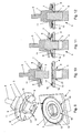
- Die Erfindung wird im Folgenden anhand mehrerer Ausführungsbeispiele unter Bezugnahme auf die zugehörigen Zeichnungen näher erläutert. Es zeigt:
- Fig.1
- eine Explosionsdarstellung einer erfindungsgemäßen Steckverbindung in einer ersten Ausführungsform,
- Fig.2 bis Fig.4
- Schnittdarstellungen des Fügens der Steckverbindung nach
Fig. 1 , - Fig.5
- eine Explosionsdarstellung der Steckverbindung in einer zweiten Ausführungsform,
- Fig.6 bis Fig.8
- Schnittdarstellungen des Fügens der Steckverbindung nach
Fig. 5 , - Fig.9
- eine Explosionsdarstellung der Steckverbindung in einer dritten Ausführungsform,
- Fig.10 bis Fig.12
- Schnittdarstellungen des Fügens der Steckverbindung nach
Fig. 9 , - Fig.13
- eine Explosionsdarstellung der Steckverbindung in einer vierten Ausführungsform und
- Fig. 14 bis Fig.16
- Schnittdarstellungen des Fügens der Steckverbindung nach
Fig. 13 . - Die Steckverbindung umfasst einen in ein glockenförmiges Gehäuse 1 eingesetzten Stecker 2 und einen ebenfalls in einem Gehäuse 3 hinter einer Frontplatte 4 aufgenommenen Gegenstecker 5. Der Stecker 2 ist mit einem in das Gehäuse 1 eingespritzten Kabel 6 verbunden. Zwischen den Gehäusen 1, 3 ist ein als Schnappfeder 7 ausgebildetes Federelement 8 zur Verriegelung des Steckers 2 mit dem Gegenstecker 5 vorgesehen. Die Schnappfeder 7 verriegelt in ihrer ersten stabilen Lage den Stecker 2 mit dem damit verbunden Gegenstecker 5 und verschiebt beim Lösen der Steckverbindung und dem damit verbundenen Übergang in ihre zweite stabile Lage den Stecker 2 relativ zu dem Gegenstecker 5 axial. Die rondenförmige Schnappfeder 7 weist radial ausgerichtete Federarme 9 und in ihrem Zentrum eine Öffnung 10 für die Steckverbindung auf.
- Nach den
Fig. 1 bis 4 ist in dem äußeren Randbereich des Gehäuses 1 des Steckers 2 ein Bund 11 ausgeformt, der die Schnappfeder 7 an ihrem äußeren Umfang fixiert. Die Schnappfeder 7 ist in ihrer zweiten stabilen Lage, im getrennten Zustand der Steckverbindung, konvex in eine zum Kabel 6 entgegengesetzte Richtung gewölbt und die Federarme 9 sind radial nach innen gerichtet. In Richtung des Zentrums weisend bilden die freien Enden der Federarme 9 die Öffnung 10, die der Stecker 2 mit seinem freien Ende 12 durchragt. - In die Frontplatte 4 des Gehäuse 3 des Gegensteckers 5 ist ein Haltekorb 13 eingesetzt, der korrespondierend zu den freien Enden der Federarme 9 einen in Richtung der Schnappfeder 7 orientierten ringförmigen Wulst 14 und im Übergangsbereich zu dem Wulst 14 einen Hinterschnitt 15 aufweist. Der Haltekorb 13 ist mittels eines peripheren Randes 16 in der Frontplatte 4 verankert.
- Zum Herstellen der Steckverbindung wird zunächst der Stecker 2 in Eingriff mit dem Gegenstecker 5 gebracht und die metallischen Federarme 9 kommen mit ihren freien Enden auf dem Wulst 14 des metallischen Haltekorbes 13 zur Auflage. Bei einer weitergehenden Steckbewegung werden die Federarme 9 der Schnappfeder 7 in Richtung des Gehäuses 1 des Steckers 2 so lange verformt, bis das Gehäuses 1 des Steckers 2 an der Frontplatte 4 des Gehäuses 3 des Gegensteckers 5 anliegt. In dieser Position des Gehäuses 1 des Steckers 2 zu dem Gehäuse 3 des Gegensteckers 5 befindet sich die Schnappfeder 7 in ihrer ersten stabilen, insbesondere metastabilen, Lage, in der die freien Enden ihrer Federarme 9 in den umlaufenden, ringförmigen Hinterschnitt 15 des Haltekorbes 13 eingreifen und damit den Stecker 2 gegenüber dem Gegenstecker 5 verriegeln. Um den für ein Überbiegen der Federarme 9 durch den Wulst 14 des Haltekorbes 13 erforderlichen Freiraum zu schaffen, ist das Gehäuse 2 des Steckers 1, ausgehend von einer Ebene in der die Schnappfeder 7 umfangsseitig gehalten ist, konkav gewölbt. Soll die Steckverbindung getrennt werden, erfolgt ein Angriff an dem Gehäuse 1 des Steckers 2 und dessen Belastung in einer entsprechenden Richtung, die nicht geradlinig auf das Gehäuse 3 des Gegensteckers 5 gerichtet ist, wodurch die Schnappfeder 7 nach dem so genannten Knackfrosch-Prinzip aus ihrer ersten stabilen Lage in die zweite stabile Lage wechselt und dabei den Stecker 2 relativ zu dem Gegenstecker 5 axial verschiebt.
- Gemäß den
Fig. 5 bis 8 ist der Bund 11 zur Befestigung der Schnappfeder 7 an ihrem äußeren Umfang an der Frontplatte 4 des Gehäuses 3 des Gegensteckers 5 ausgeformt. Die Schnappfeder 7 ist im getrennten Zustand der Steckverbindung konvex in eine zum Gegenstecker 5 entgegengesetzte Richtung gewölbt und befindet sich in ihrer zweiten stabilen Lage, wobei die Federarme 9 radial nach innen gerichtet sind und im Zentrum der Schnappfeder 7 eine Öffnung 10 für die Steckverbindung bilden. Der Gegenstecker 5 liegt mit seinem freien Ende 17 an der der Schnappfeder 7 abgewandten Seite der Frontplatte 4 an der Frontplatte 4 an, in die eine Freimachung 18 hinter der Schnappfeder 7 für deren freien Enden der Federarme 9 in der ersten stabilen Lage eingelassen ist. - Der Haltekorb 13 ist über seinen äußeren Rand 16 in dem Gehäuse 1 des Steckers 2 gehalten und sein sich in Richtung des freien Endes des Steckers 2 erstreckender Wulst 14 ist durch einen koaxial zum äußeren Umfang des Gehäuses 1 des Steckers 2 ausgerichteten Ring 23, der Bestandteil des Gehäuses 2 ist, zentriert. Zum Herstellen der Steckverbindung wird zunächst der Stecker 2 in Eingriff mit dem Gegenstecker 5 gebracht, wobei die Federarme 9 mit ihren freien Enden auf dem Wulst 14 des Haltekorbes 13 zur Auflage kommen. In einer fortgeführten Bewegung werden die Federarme 9 der Schnappfeder 7 in Richtung des Gehäuses 1 des Gegensteckers 2 verformt, bis das Gehäuses 1 des Steckers 2 an der Frontplatte 4 des Gehäuses 3 des Gegensteckers 5 anliegt. In dieser Position des Gehäuses 1 des Steckers 2 zu dem Gehäuse 3 des Gegensteckers 5 befindet sich die Schnappfeder 7 in ihrer ersten stabilen Lage, in der die freien Enden ihrer Federarme 9 in den Hinterschnitt 15 des Haltekorbes 13 eingreifen und damit den Stecker 2 gegenüber dem Gegenstecker 5 verriegeln. Eine Trennung der Steckverbindung erfolgt wie bereits erläutert.
- Den
Fig. 9 bis 12 ist zu entnehmen, dass der Bund 11 zur Befestigung der Schnappfeder 7 in deren Öffnung 10 eingreift und demnach um den Stecker 2 herum in Zentrum des Gehäuses 1 des Steckers ausgeformt ist. In dieser Ausführungsform sind die Federarme 9 radial nach außen, zum freien Ende 12 des Steckers 2 weisend, gerichtet und die Schnappfeder 7 ist im getrennten Zustand der Steckverbindung in ihrer zweiten stabilen Lage konkav geformt. Der Bund 11 haltert die Schnappfeder 7 derart beabstandet zum zugeordneten Gehäuse 1, dass die freien Enden der Federarme 9 zur Einnahme der ersten stabilen Lage in Richtung des Kabels 6 weisend überbogen werden können. Der Haltekorb 13 ist über seinen äußeren Rand 16 in dem Gehäuse 3 des Gegensteckers 5 gehalten, wobei sein in Richtung des Steckers 2 weisender Wulst 14 durch einen koaxial zum äußeren Umfang der Schnappfeder 7 ausgerichteten Ring 19, der Bestandteil des Gehäuses 3 ist, zentriert ist. Im Übrigen ist der Haltekorb 13 der konkaven Wölbung der Frontplatte 4 des Gehäuses 3 des Gegensteckers 5 folgend in die Frontplatte 4 eingelassen. - Die Steckverbindung wird hergestellt, in dem der Stecker 2 in Eingriff mit dem Gegenstecker 5 gebracht wird. Ab einer bestimmten Fügeposition liegen die Federarme 9 mit ihren freien Enden auf dem Haltekorb 13 auf und bewegen sich bei einer fortgeführten Steckbewegung in Richtung des Wulstes 14, wo sie in den Hinterschnitt 15 eingreifen. Anschließend werden die Federarme 9 überbogen, damit die Schnappfeder 7 ihre erste stabile Lage einnimmt, in der der Stecker 2 gegenüber dem Gegenstecker 5 verriegelt ist. Die Trennung der Steckverbindung wird wie bereits beschrieben vorgenommen.
- Nach den
Fig. 13 bis 16 ist der Bund 11 zur Befestigung der Schnappfeder 7, der in deren Öffnung 10 eingreift, dem Gehäuse 3 des Gegensteckers 5 zugeordnet und um den Gegenstecker 5 herum im Zentrum des Gehäuses 3 ausgeformt. Die Federarme 9 weisen mit ihren freien Enden radial nach außen, und sind in einer zur Frontplatte 4 entgegengesetzten Richtung derart gebogen, dass die Schnappfeder 7 im getrennten Zustand der Steckverbindung in ihrer zweiten stabilen Lage konkav geformt ist. Der Bund 11 haltert die Schnappfeder 7 derart beabstandet zur Frontplatte 4, dass die freien Enden der Federarme 9 zur Einnahme der ersten stabilen Lage in Richtung des Gegensteckers 5 weisend zu überbiegen sind. Der Haltekorb 13 ist über seinen äußeren Rand 16 in dem Gehäuse 1 des Steckers 2 gehalten, wobei sein in entgegengesetzter Richtung zum Kabel 6 weisender Wulst 14 durch einen koaxial zum äußeren Umfang des entsprechenden Gehäuses 1 ausgerichteten Ring 20, der Bestandteil des Gehäuses 1 ist, zentriert ist. Im weiteren Verlauf ist der Haltekorb 13 an die konkave Wölbung des Gehäuses 1 des Steckers 2 angepasst und bündig in das Gehäuse 1 eingelassen. Der Stecker 2 ist über einen Toleranzausgleich 21 in Form einer Freimachung 22 in dem Gehäuse 1 fixiert. Die Freimachung 22 erlaubt eine geringe Lageänderung des Steckers 2 und ermöglicht einen Ausgleich von Ungenauigkeiten zwischen dem Stecker 2 und dem Gegenstecker 5. - Beim Herstellen der Steckverbindung wird der Stecker 2 mit dem Gegenstecker 5 gefügt und in einer bestimmten Position liegen die Federarme 9 mit ihren freien Enden auf dem Haltekorb 13 auf. Beim weiteren Fügen bewegen sich die freien Enden der Federarme 9 in Richtung des Wulstes 14, wo sie in den ringförmigen Hinterschnitt 15 eingreifen. Anschließend werden die Federarme 9 überbogen, damit die Schnappfeder 7 ihre erste stabile Lage einnimmt, in der der Stecker 2 gegenüber dem Gegenstecker 5 verriegelt ist. Die Trennung der Steckverbindung wird, wie bereits erläutert, vorgenommen.
Claims (10)
- Elektrische Steckverbindung, die einen Stecker (2) und einen Gegenstecker (5) mit jeweils einem Gehäuse (1, 3) umfasst, wobei ein zwischen den Gehäusen (1, 3) wirkendes Federelement (8) zur Verriegelung des Steckers (2) mit dem Gegenstecker (5) vorgesehen und als einem der Gehäuse (1, 3) zugeordnete Schnappfeder (7) ausgebildet ist, die in ihrer ersten stabilen Lage den Stecker (2) mit dem damit verbunden Gegenstecker (5) verriegelt und beim Lösen der Steckverbindung und dem damit verbundenen Übergang in ihre zweite stabile Lage den Stecker (2) relativ zu dem Gegenstecker (5) axial verschiebt, wobei die Schnappfeder mehrere radial ausgerichtete Federarme (9) und in ihrem Zentrum eine Öffnung (10) aufweist, eines der Gehäuse (1, 3) mit einem die Schnappfeder (7) fixierenden Bund (11) und das andere Gehäuse (1, 3) mit einem Hinterschnitt (15) zum Eingriff der freien Enden der Federarme (9) im verriegelten Zustand der Steckverbindung versehen ist und der Bund (11) entweder in die Öffnung (10) der Schnappfeder (7) eingreift, wobei die Federarme (9) radial nach außen gerichtet sind, oder die Schnappfeder (7) an ihrem äußeren Umfang fixiert, wobei die Federarme (9) radial nach innen gerichtet sind, und der Hinterschnitt (15) entweder für die radial nach außen oder die radial nach innen wirkenden Federarme (9) ausgebildet ist.
- Steckverbindung nach Anspruch 1, dadurch gekennzeichnet, dass die Schnappfeder (7) rondenförmig ausgebildet ist und vier bis acht Federarme (9) aufweist.
- Steckverbindung nach Anspruch 1, dadurch gekennzeichnet, dass die Öffnung (10) in der Schnappfeder (7) zur Herstellung der Steckverbindung dient.
- Steckverbindung nach Anspruch 1, dadurch gekennzeichnet, dass an dem den Hinterschnitt (15) aufweisenden Gehäuse (1, 3) ein ringförmiger Wulst (14) ausgebildet ist, der beim Fügen der Steckverbindung die freien Enden der Federarme (9) zur Einnahme der ersten stabilen Lage der Schnappfeder (7) betätigt, in der der Stecker (2) mit dem Gegenstecker (5) verriegelt ist.
- Steckverbindung nach Anspruch 1, dadurch gekennzeichnet, dass der Hinterschnitt (15) in einem in das Gehäuse (1, 3) eingesetzten Haltekorb (13) ausgebildet ist.
- Steckverbindung nach einem der Ansprüche 1 bis 5, dadurch gekennzeichnet, dass der Stecker (2) über einen Toleranzausgleich (21) in dem Gehäuse (1) fixiert ist.
- Steckverbindung nach einem der Ansprüche 1 oder 6, dadurch gekennzeichnet, dass der Stecker (2) mit seinem freien Ende aus seinem, insbesondere glockenförmigen, Gehäuse (1) herausragt.
- Steckverbindung nach einem der Ansprüche 1 bis 5, dadurch gekennzeichnet, dass das Gehäuse (3) des Gegensteckers(5) im Bereich der Trennebene der Steckverbindung eine Frontplatte (4) aufweist.
- Steckverbindung nach Anspruch 8, dadurch gekennzeichnet, dass der Gegenstecker (5) endseitig an der Frontplatte (4) anliegt.
- Steckverbindung nach einem der Ansprüche 1 bis 9, dadurch gekennzeichnet, dass die Schnappfeder (7) und/oder ein mit dem Stecker (2) verbundenes Kabel (6) und/oder der Haltekorb (13) mit Kunststoff am jeweiligen Gehäuse (1, 3), umspritzt ist.
Applications Claiming Priority (1)
| Application Number | Priority Date | Filing Date | Title |
|---|---|---|---|
| DE200910014876 DE102009014876B4 (de) | 2009-03-25 | 2009-03-25 | Elektrische Steckverbindung |
Publications (3)
| Publication Number | Publication Date |
|---|---|
| EP2234218A2 true EP2234218A2 (de) | 2010-09-29 |
| EP2234218A3 EP2234218A3 (de) | 2012-04-25 |
| EP2234218B1 EP2234218B1 (de) | 2013-06-12 |
Family
ID=42235298
Family Applications (1)
| Application Number | Title | Priority Date | Filing Date |
|---|---|---|---|
| EP20100003103 Not-in-force EP2234218B1 (de) | 2009-03-25 | 2010-03-24 | Elektrische Steckverbindung |
Country Status (2)
| Country | Link |
|---|---|
| EP (1) | EP2234218B1 (de) |
| DE (1) | DE102009014876B4 (de) |
Cited By (1)
| Publication number | Priority date | Publication date | Assignee | Title |
|---|---|---|---|---|
| WO2019192845A1 (de) * | 2018-04-04 | 2019-10-10 | Phoenix Contact Gmbh & Co. Kg | Steckverbindersystem mit einem bistabilen element |
Families Citing this family (1)
| Publication number | Priority date | Publication date | Assignee | Title |
|---|---|---|---|---|
| DE102015013383B3 (de) * | 2015-10-14 | 2016-10-20 | Florian Schlereth | Steckdose |
Citations (3)
| Publication number | Priority date | Publication date | Assignee | Title |
|---|---|---|---|---|
| JPH09306594A (ja) | 1996-05-21 | 1997-11-28 | Sumitomo Wiring Syst Ltd | コネクタ |
| EP0863576A1 (de) | 1997-03-05 | 1998-09-09 | Ryosei Electro-Circuit Systems Ltd. | Elektrischer Steckverbinder |
| GB2338124B (en) | 1998-04-29 | 2002-08-21 | Static Systems Group Plc | A releasable plug |
Family Cites Families (1)
| Publication number | Priority date | Publication date | Assignee | Title |
|---|---|---|---|---|
| CN2896603Y (zh) * | 2006-09-29 | 2007-05-02 | 瞿金良 | 快插、自锁型射频同轴连接器 |
-
2009
- 2009-03-25 DE DE200910014876 patent/DE102009014876B4/de not_active Expired - Fee Related
-
2010
- 2010-03-24 EP EP20100003103 patent/EP2234218B1/de not_active Not-in-force
Patent Citations (3)
| Publication number | Priority date | Publication date | Assignee | Title |
|---|---|---|---|---|
| JPH09306594A (ja) | 1996-05-21 | 1997-11-28 | Sumitomo Wiring Syst Ltd | コネクタ |
| EP0863576A1 (de) | 1997-03-05 | 1998-09-09 | Ryosei Electro-Circuit Systems Ltd. | Elektrischer Steckverbinder |
| GB2338124B (en) | 1998-04-29 | 2002-08-21 | Static Systems Group Plc | A releasable plug |
Cited By (1)
| Publication number | Priority date | Publication date | Assignee | Title |
|---|---|---|---|---|
| WO2019192845A1 (de) * | 2018-04-04 | 2019-10-10 | Phoenix Contact Gmbh & Co. Kg | Steckverbindersystem mit einem bistabilen element |
Also Published As
| Publication number | Publication date |
|---|---|
| DE102009014876B4 (de) | 2011-05-05 |
| EP2234218A3 (de) | 2012-04-25 |
| DE102009014876A1 (de) | 2010-09-30 |
| EP2234218B1 (de) | 2013-06-12 |
Similar Documents
| Publication | Publication Date | Title |
|---|---|---|
| EP2957000B1 (de) | Elektrischer rundsteckverbinder mit push-pull-verriegelung | |
| EP3895256B1 (de) | Rundsteckverbinder mit verriegelung | |
| EP2439439B1 (de) | Verbindungselement für eine Fluidverbindung | |
| EP3631275B1 (de) | Kupplungselement zum verbinden einer ersten fluidführenden leitung mit einer zweiten fluidführenden leitung sowie kupplungsanordnung | |
| DE202007013637U1 (de) | Elektrische oder optische Steckverbindung | |
| WO1995004390A1 (de) | Steckverbinderpaar | |
| DE102008009350A1 (de) | Steckverbindung mit einer Kodiervorrichtung und Verfahren zur Montage der Kodiervorrichtung an der Steckverbindung | |
| DE102008045801A1 (de) | Photovoltaik-Steckverbindung | |
| EP2413012B1 (de) | Steckverbindung | |
| DE2323180A1 (de) | Verriegelung fuer einen elektrischen steckverbinder | |
| EP2748492A1 (de) | Kolbenstangenanbindung | |
| EP2707639A1 (de) | Verbindungseinrichtung sowie verbindungssystem mit einer solchen | |
| DE102022101100A1 (de) | Fluidverbindung | |
| WO2019076620A1 (de) | Steckverbinderteil mit einem verriegelungselement | |
| EP2234218B1 (de) | Elektrische Steckverbindung | |
| EP2733403B1 (de) | Kupplungseinrichtung für Medienleitungen | |
| EP3312944B1 (de) | Push-pull-steckverbinderteil mit einem rastblech | |
| WO2021244925A1 (de) | Vorrichtung zum verbinden zweier röhrenförmiger objekte | |
| EP2504890B1 (de) | Leicht zu reinigender steckverbinder | |
| DE202007005073U1 (de) | Elektrischer Steckverbinder | |
| DE102006040254B4 (de) | Rundsteckverbinder | |
| EP2607769B1 (de) | Verbindungseinheit und eine derartige Verbindungseinheit umfassende Verbindungsanordnung zur Herstellung einer unlösbaren Verbindung medienführender Leitungen | |
| DE102005011777B4 (de) | Schnellkupplung für ein Rohrsystem | |
| EP1467451A1 (de) | Kuppler einer koaxialen Steckverbindung | |
| DE102012106734A1 (de) | Verbindungseinrichtung sowie Verbindungssystem mit einer solchen |
Legal Events
| Date | Code | Title | Description |
|---|---|---|---|
| PUAI | Public reference made under article 153(3) epc to a published international application that has entered the european phase |
Free format text: ORIGINAL CODE: 0009012 |
|
| AK | Designated contracting states |
Kind code of ref document: A2 Designated state(s): AT BE BG CH CY CZ DE DK EE ES FI FR GB GR HR HU IE IS IT LI LT LU LV MC MK MT NL NO PL PT RO SE SI SK SM TR |
|
| AX | Request for extension of the european patent |
Extension state: AL BA ME RS |
|
| PUAL | Search report despatched |
Free format text: ORIGINAL CODE: 0009013 |
|
| AK | Designated contracting states |
Kind code of ref document: A3 Designated state(s): AT BE BG CH CY CZ DE DK EE ES FI FR GB GR HR HU IE IS IT LI LT LU LV MC MK MT NL NO PL PT RO SE SI SK SM TR |
|
| AX | Request for extension of the european patent |
Extension state: AL BA ME RS |
|
| RIC1 | Information provided on ipc code assigned before grant |
Ipc: H01R 13/627 20060101AFI20120320BHEP |
|
| GRAP | Despatch of communication of intention to grant a patent |
Free format text: ORIGINAL CODE: EPIDOSNIGR1 |
|
| 17P | Request for examination filed |
Effective date: 20121023 |
|
| GRAS | Grant fee paid |
Free format text: ORIGINAL CODE: EPIDOSNIGR3 |
|
| GRAA | (expected) grant |
Free format text: ORIGINAL CODE: 0009210 |
|
| AK | Designated contracting states |
Kind code of ref document: B1 Designated state(s): AT BE BG CH CY CZ DE DK EE ES FI FR GB GR HR HU IE IS IT LI LT LU LV MC MK MT NL NO PL PT RO SE SI SK SM TR |
|
| REG | Reference to a national code |
Ref country code: GB Ref legal event code: FG4D Free format text: NOT ENGLISH |
|
| REG | Reference to a national code |
Ref country code: CH Ref legal event code: EP |
|
| REG | Reference to a national code |
Ref country code: AT Ref legal event code: REF Ref document number: 616986 Country of ref document: AT Kind code of ref document: T Effective date: 20130615 |
|
| REG | Reference to a national code |
Ref country code: IE Ref legal event code: FG4D Free format text: LANGUAGE OF EP DOCUMENT: GERMAN |
|
| REG | Reference to a national code |
Ref country code: DE Ref legal event code: R096 Ref document number: 502010003616 Country of ref document: DE Effective date: 20130808 |
|
| PG25 | Lapsed in a contracting state [announced via postgrant information from national office to epo] |
Ref country code: ES Free format text: LAPSE BECAUSE OF FAILURE TO SUBMIT A TRANSLATION OF THE DESCRIPTION OR TO PAY THE FEE WITHIN THE PRESCRIBED TIME-LIMIT Effective date: 20130923 Ref country code: NO Free format text: LAPSE BECAUSE OF FAILURE TO SUBMIT A TRANSLATION OF THE DESCRIPTION OR TO PAY THE FEE WITHIN THE PRESCRIBED TIME-LIMIT Effective date: 20130912 Ref country code: FI Free format text: LAPSE BECAUSE OF FAILURE TO SUBMIT A TRANSLATION OF THE DESCRIPTION OR TO PAY THE FEE WITHIN THE PRESCRIBED TIME-LIMIT Effective date: 20130612 Ref country code: LT Free format text: LAPSE BECAUSE OF FAILURE TO SUBMIT A TRANSLATION OF THE DESCRIPTION OR TO PAY THE FEE WITHIN THE PRESCRIBED TIME-LIMIT Effective date: 20130612 Ref country code: SE Free format text: LAPSE BECAUSE OF FAILURE TO SUBMIT A TRANSLATION OF THE DESCRIPTION OR TO PAY THE FEE WITHIN THE PRESCRIBED TIME-LIMIT Effective date: 20130612 Ref country code: GR Free format text: LAPSE BECAUSE OF FAILURE TO SUBMIT A TRANSLATION OF THE DESCRIPTION OR TO PAY THE FEE WITHIN THE PRESCRIBED TIME-LIMIT Effective date: 20130913 Ref country code: SI Free format text: LAPSE BECAUSE OF FAILURE TO SUBMIT A TRANSLATION OF THE DESCRIPTION OR TO PAY THE FEE WITHIN THE PRESCRIBED TIME-LIMIT Effective date: 20130612 |
|
| REG | Reference to a national code |
Ref country code: NL Ref legal event code: VDEP Effective date: 20130612 |
|
| REG | Reference to a national code |
Ref country code: LT Ref legal event code: MG4D |
|
| PG25 | Lapsed in a contracting state [announced via postgrant information from national office to epo] |
Ref country code: BG Free format text: LAPSE BECAUSE OF FAILURE TO SUBMIT A TRANSLATION OF THE DESCRIPTION OR TO PAY THE FEE WITHIN THE PRESCRIBED TIME-LIMIT Effective date: 20130912 Ref country code: HR Free format text: LAPSE BECAUSE OF FAILURE TO SUBMIT A TRANSLATION OF THE DESCRIPTION OR TO PAY THE FEE WITHIN THE PRESCRIBED TIME-LIMIT Effective date: 20130612 |
|
| PG25 | Lapsed in a contracting state [announced via postgrant information from national office to epo] |
Ref country code: LV Free format text: LAPSE BECAUSE OF FAILURE TO SUBMIT A TRANSLATION OF THE DESCRIPTION OR TO PAY THE FEE WITHIN THE PRESCRIBED TIME-LIMIT Effective date: 20130612 |
|
| PG25 | Lapsed in a contracting state [announced via postgrant information from national office to epo] |
Ref country code: IS Free format text: LAPSE BECAUSE OF FAILURE TO SUBMIT A TRANSLATION OF THE DESCRIPTION OR TO PAY THE FEE WITHIN THE PRESCRIBED TIME-LIMIT Effective date: 20131012 Ref country code: PT Free format text: LAPSE BECAUSE OF FAILURE TO SUBMIT A TRANSLATION OF THE DESCRIPTION OR TO PAY THE FEE WITHIN THE PRESCRIBED TIME-LIMIT Effective date: 20131014 Ref country code: CZ Free format text: LAPSE BECAUSE OF FAILURE TO SUBMIT A TRANSLATION OF THE DESCRIPTION OR TO PAY THE FEE WITHIN THE PRESCRIBED TIME-LIMIT Effective date: 20130612 Ref country code: EE Free format text: LAPSE BECAUSE OF FAILURE TO SUBMIT A TRANSLATION OF THE DESCRIPTION OR TO PAY THE FEE WITHIN THE PRESCRIBED TIME-LIMIT Effective date: 20130612 Ref country code: SK Free format text: LAPSE BECAUSE OF FAILURE TO SUBMIT A TRANSLATION OF THE DESCRIPTION OR TO PAY THE FEE WITHIN THE PRESCRIBED TIME-LIMIT Effective date: 20130612 |
|
| PG25 | Lapsed in a contracting state [announced via postgrant information from national office to epo] |
Ref country code: RO Free format text: LAPSE BECAUSE OF FAILURE TO SUBMIT A TRANSLATION OF THE DESCRIPTION OR TO PAY THE FEE WITHIN THE PRESCRIBED TIME-LIMIT Effective date: 20130612 Ref country code: PL Free format text: LAPSE BECAUSE OF FAILURE TO SUBMIT A TRANSLATION OF THE DESCRIPTION OR TO PAY THE FEE WITHIN THE PRESCRIBED TIME-LIMIT Effective date: 20130612 Ref country code: NL Free format text: LAPSE BECAUSE OF FAILURE TO SUBMIT A TRANSLATION OF THE DESCRIPTION OR TO PAY THE FEE WITHIN THE PRESCRIBED TIME-LIMIT Effective date: 20130612 |
|
| REG | Reference to a national code |
Ref country code: DE Ref legal event code: R097 Ref document number: 502010003616 Country of ref document: DE |
|
| PLBE | No opposition filed within time limit |
Free format text: ORIGINAL CODE: 0009261 |
|
| STAA | Information on the status of an ep patent application or granted ep patent |
Free format text: STATUS: NO OPPOSITION FILED WITHIN TIME LIMIT |
|
| PG25 | Lapsed in a contracting state [announced via postgrant information from national office to epo] |
Ref country code: DK Free format text: LAPSE BECAUSE OF FAILURE TO SUBMIT A TRANSLATION OF THE DESCRIPTION OR TO PAY THE FEE WITHIN THE PRESCRIBED TIME-LIMIT Effective date: 20130612 |
|
| 26N | No opposition filed |
Effective date: 20140313 |
|
| REG | Reference to a national code |
Ref country code: DE Ref legal event code: R081 Ref document number: 502010003616 Country of ref document: DE Owner name: BOIDA KUNSTSTOFFTECHNIK GMBH, DE Free format text: FORMER OWNER: BOIDA KUNSTSTOFFTECHNIK GMBH & CO. KG, 35428 LANGGOENS, DE Effective date: 20140410 Ref country code: DE Ref legal event code: R082 Ref document number: 502010003616 Country of ref document: DE Representative=s name: GAIL & KOLLEGEN RECHTSANWAELTE, DE Effective date: 20140410 Ref country code: DE Ref legal event code: R082 Ref document number: 502010003616 Country of ref document: DE Representative=s name: GAIL & KOLLEGEN RECHTSANWAELTE, DE Effective date: 20130912 Ref country code: DE Ref legal event code: R082 Ref document number: 502010003616 Country of ref document: DE Representative=s name: GAIL & KOLLEGEN RECHTS- UND PATENTANWAELTE, DE Effective date: 20130912 Ref country code: DE Ref legal event code: R082 Ref document number: 502010003616 Country of ref document: DE Representative=s name: GAIL & KOLLEGEN RECHTS- UND PATENTANWAELTE, DE Effective date: 20140410 |
|
| PG25 | Lapsed in a contracting state [announced via postgrant information from national office to epo] |
Ref country code: IT Free format text: LAPSE BECAUSE OF FAILURE TO SUBMIT A TRANSLATION OF THE DESCRIPTION OR TO PAY THE FEE WITHIN THE PRESCRIBED TIME-LIMIT Effective date: 20130612 |
|
| REG | Reference to a national code |
Ref country code: DE Ref legal event code: R097 Ref document number: 502010003616 Country of ref document: DE Effective date: 20140313 |
|
| PG25 | Lapsed in a contracting state [announced via postgrant information from national office to epo] |
Ref country code: LU Free format text: LAPSE BECAUSE OF FAILURE TO SUBMIT A TRANSLATION OF THE DESCRIPTION OR TO PAY THE FEE WITHIN THE PRESCRIBED TIME-LIMIT Effective date: 20140324 |
|
| PGFP | Annual fee paid to national office [announced via postgrant information from national office to epo] |
Ref country code: DE Payment date: 20140918 Year of fee payment: 5 |
|
| REG | Reference to a national code |
Ref country code: CH Ref legal event code: PL |
|
| GBPC | Gb: european patent ceased through non-payment of renewal fee |
Effective date: 20140324 |
|
| REG | Reference to a national code |
Ref country code: FR Ref legal event code: ST Effective date: 20141128 |
|
| REG | Reference to a national code |
Ref country code: IE Ref legal event code: MM4A |
|
| PG25 | Lapsed in a contracting state [announced via postgrant information from national office to epo] |
Ref country code: IE Free format text: LAPSE BECAUSE OF NON-PAYMENT OF DUE FEES Effective date: 20140324 Ref country code: FR Free format text: LAPSE BECAUSE OF NON-PAYMENT OF DUE FEES Effective date: 20140331 Ref country code: GB Free format text: LAPSE BECAUSE OF NON-PAYMENT OF DUE FEES Effective date: 20140324 Ref country code: CH Free format text: LAPSE BECAUSE OF NON-PAYMENT OF DUE FEES Effective date: 20140331 Ref country code: LI Free format text: LAPSE BECAUSE OF NON-PAYMENT OF DUE FEES Effective date: 20140331 |
|
| REG | Reference to a national code |
Ref country code: DE Ref legal event code: R119 Ref document number: 502010003616 Country of ref document: DE |
|
| PG25 | Lapsed in a contracting state [announced via postgrant information from national office to epo] |
Ref country code: DE Free format text: LAPSE BECAUSE OF NON-PAYMENT OF DUE FEES Effective date: 20151001 |
|
| PG25 | Lapsed in a contracting state [announced via postgrant information from national office to epo] |
Ref country code: MT Free format text: LAPSE BECAUSE OF FAILURE TO SUBMIT A TRANSLATION OF THE DESCRIPTION OR TO PAY THE FEE WITHIN THE PRESCRIBED TIME-LIMIT Effective date: 20130612 |
|
| PG25 | Lapsed in a contracting state [announced via postgrant information from national office to epo] |
Ref country code: SM Free format text: LAPSE BECAUSE OF FAILURE TO SUBMIT A TRANSLATION OF THE DESCRIPTION OR TO PAY THE FEE WITHIN THE PRESCRIBED TIME-LIMIT Effective date: 20130612 |
|
| REG | Reference to a national code |
Ref country code: AT Ref legal event code: MM01 Ref document number: 616986 Country of ref document: AT Kind code of ref document: T Effective date: 20150324 |
|
| PG25 | Lapsed in a contracting state [announced via postgrant information from national office to epo] |
Ref country code: MC Free format text: LAPSE BECAUSE OF FAILURE TO SUBMIT A TRANSLATION OF THE DESCRIPTION OR TO PAY THE FEE WITHIN THE PRESCRIBED TIME-LIMIT Effective date: 20130612 |
|
| PG25 | Lapsed in a contracting state [announced via postgrant information from national office to epo] |
Ref country code: CY Free format text: LAPSE BECAUSE OF FAILURE TO SUBMIT A TRANSLATION OF THE DESCRIPTION OR TO PAY THE FEE WITHIN THE PRESCRIBED TIME-LIMIT Effective date: 20130612 |
|
| PG25 | Lapsed in a contracting state [announced via postgrant information from national office to epo] |
Ref country code: TR Free format text: LAPSE BECAUSE OF FAILURE TO SUBMIT A TRANSLATION OF THE DESCRIPTION OR TO PAY THE FEE WITHIN THE PRESCRIBED TIME-LIMIT Effective date: 20130612 Ref country code: HU Free format text: LAPSE BECAUSE OF FAILURE TO SUBMIT A TRANSLATION OF THE DESCRIPTION OR TO PAY THE FEE WITHIN THE PRESCRIBED TIME-LIMIT; INVALID AB INITIO Effective date: 20100324 Ref country code: BE Free format text: LAPSE BECAUSE OF FAILURE TO SUBMIT A TRANSLATION OF THE DESCRIPTION OR TO PAY THE FEE WITHIN THE PRESCRIBED TIME-LIMIT Effective date: 20140331 |
|
| PG25 | Lapsed in a contracting state [announced via postgrant information from national office to epo] |
Ref country code: AT Free format text: LAPSE BECAUSE OF NON-PAYMENT OF DUE FEES Effective date: 20150324 |
|
| PG25 | Lapsed in a contracting state [announced via postgrant information from national office to epo] |
Ref country code: MK Free format text: LAPSE BECAUSE OF FAILURE TO SUBMIT A TRANSLATION OF THE DESCRIPTION OR TO PAY THE FEE WITHIN THE PRESCRIBED TIME-LIMIT Effective date: 20130612 |