EP2234085B1 - Parking availability judging device for vehicle - Google Patents
Parking availability judging device for vehicle Download PDFInfo
- Publication number
- EP2234085B1 EP2234085B1 EP08862257A EP08862257A EP2234085B1 EP 2234085 B1 EP2234085 B1 EP 2234085B1 EP 08862257 A EP08862257 A EP 08862257A EP 08862257 A EP08862257 A EP 08862257A EP 2234085 B1 EP2234085 B1 EP 2234085B1
- Authority
- EP
- European Patent Office
- Prior art keywords
- parking space
- parking
- reflection point
- vehicle
- reflection
- Prior art date
- Legal status (The legal status is an assumption and is not a legal conclusion. Google has not performed a legal analysis and makes no representation as to the accuracy of the status listed.)
- Not-in-force
Links
Images


Classifications
-
- G—PHYSICS
- G08—SIGNALLING
- G08G—TRAFFIC CONTROL SYSTEMS
- G08G1/00—Traffic control systems for road vehicles
- G08G1/14—Traffic control systems for road vehicles indicating individual free spaces in parking areas
-
- B—PERFORMING OPERATIONS; TRANSPORTING
- B62—LAND VEHICLES FOR TRAVELLING OTHERWISE THAN ON RAILS
- B62D—MOTOR VEHICLES; TRAILERS
- B62D15/00—Steering not otherwise provided for
- B62D15/02—Steering position indicators ; Steering position determination; Steering aids
- B62D15/027—Parking aids, e.g. instruction means
-
- G—PHYSICS
- G08—SIGNALLING
- G08G—TRAFFIC CONTROL SYSTEMS
- G08G1/00—Traffic control systems for road vehicles
- G08G1/16—Anti-collision systems
- G08G1/165—Anti-collision systems for passive traffic, e.g. including static obstacles, trees
-
- G—PHYSICS
- G08—SIGNALLING
- G08G—TRAFFIC CONTROL SYSTEMS
- G08G1/00—Traffic control systems for road vehicles
- G08G1/16—Anti-collision systems
- G08G1/168—Driving aids for parking, e.g. acoustic or visual feedback on parking space
-
- G—PHYSICS
- G01—MEASURING; TESTING
- G01S—RADIO DIRECTION-FINDING; RADIO NAVIGATION; DETERMINING DISTANCE OR VELOCITY BY USE OF RADIO WAVES; LOCATING OR PRESENCE-DETECTING BY USE OF THE REFLECTION OR RERADIATION OF RADIO WAVES; ANALOGOUS ARRANGEMENTS USING OTHER WAVES
- G01S15/00—Systems using the reflection or reradiation of acoustic waves, e.g. sonar systems
- G01S15/88—Sonar systems specially adapted for specific applications
- G01S15/93—Sonar systems specially adapted for specific applications for anti-collision purposes
- G01S15/931—Sonar systems specially adapted for specific applications for anti-collision purposes of land vehicles
- G01S2015/932—Sonar systems specially adapted for specific applications for anti-collision purposes of land vehicles for parking operations
- G01S2015/933—Sonar systems specially adapted for specific applications for anti-collision purposes of land vehicles for parking operations for measuring the dimensions of the parking space when driving past
- G01S2015/935—Sonar systems specially adapted for specific applications for anti-collision purposes of land vehicles for parking operations for measuring the dimensions of the parking space when driving past for measuring the contour, e.g. a trajectory of measurement points, representing the boundary of the parking space
-
- G—PHYSICS
- G01—MEASURING; TESTING
- G01S—RADIO DIRECTION-FINDING; RADIO NAVIGATION; DETERMINING DISTANCE OR VELOCITY BY USE OF RADIO WAVES; LOCATING OR PRESENCE-DETECTING BY USE OF THE REFLECTION OR RERADIATION OF RADIO WAVES; ANALOGOUS ARRANGEMENTS USING OTHER WAVES
- G01S15/00—Systems using the reflection or reradiation of acoustic waves, e.g. sonar systems
- G01S15/88—Sonar systems specially adapted for specific applications
- G01S15/93—Sonar systems specially adapted for specific applications for anti-collision purposes
- G01S15/931—Sonar systems specially adapted for specific applications for anti-collision purposes of land vehicles
- G01S2015/932—Sonar systems specially adapted for specific applications for anti-collision purposes of land vehicles for parking operations
- G01S2015/933—Sonar systems specially adapted for specific applications for anti-collision purposes of land vehicles for parking operations for measuring the dimensions of the parking space when driving past
- G01S2015/936—Sonar systems specially adapted for specific applications for anti-collision purposes of land vehicles for parking operations for measuring the dimensions of the parking space when driving past for measuring parking spaces extending transverse or diagonal to the driving direction, i.e. not parallel to the driving direction
Definitions
- the present invention relates to a vehicular parking feasibility determining system for accurately determining the existence of a parking space that can be parked in, a vehicular space detection system for accurately determining the existence of a parking space that can be parked in from a position just before it, and a vehicular movable range detection system for accurately determining the existence of a subject vehicle movable range for parking in a parking space.
- a vehicular parking feasibility determining system is known from US 2005/028758 A1 .
- US 4,931,930 A teaches to calculate a movable range in the vehicle wide direction based on a sequence, of rejection points detected from electromagnetic waves transmitted by transceiving means and reflected from an object.
- the feasibility of parking is determined based on the width of a parking space, and there is the problem that since the width of the road is not taken into consideration, it cannot determine a case in which parking is actually impossible due to the width of the road being narrow although the width of the parking space is sufficient, and a case in which parking becomes possible by maneuvering back-and-forth.
- the present invention has been accomplished in light of the above-mentioned circumstances, and it is an object thereof to provide a vehicular parking feasibility determining system that enables the existence of a parking space that can be parked in to be accurately determined.
- a vehicular parking feasibility determining system comprising transceiving means that transmits electromagnetic waves so as to scan a predetermined angular range in the horizontal direction around a subject vehicle at predetermined time intervals, and receives reflected waves of the electromagnetic waves reflected from an object, reflection point detection means that detects a reflection point at which electromagnetic waves are reflected from the object based on the result of reception of rejected waves by the transceiving means, parking space existence determining means that determines the existence of a parking space based on pre-stored subject vehicle body dimensional data and a sequence of the reflection points, and parking feasibility determining means that determines the feasibility of parking the subject vehicle from a current position thereof to the parking space, characterized in that the system comprises movable range calculation means that calculates a movable range in the subject vehicle width direction based on the sequence of reflection points, and parking space width calculation means that calculates a width of the parking space in subject vehicle length direction based on the sequence of
- the system comprises processing region setting means that sets a predetermined processing region formed from a first range in the subject vehicle width direction and a second range in subject vehicle length direction, the parking space existence determining means determining that the parking space exists when, among reflection points present within the processing region, a distance in the vehicle length direction between a pair of reflection points of the electromagnetic waves with adjacent angles in the horizontal direction is a predetermined value or greater.
- the system comprises boundary line calculation means that calculates as a vehicle width direction boundary line a straight line for which the sum of the distances in the vehicle width direction to the reflection points present within the processing region is a minimum, and calculates as a vehicle length direction boundary line a straight line for which the sum of the distances in subject vehicle length direction therefrom is a minimum, the movable range calculation means setting the processing region on left and right with the subject vehicle body axis as the center, and calculating as a movable range the minimum distance among the distances in the vehicle width direction of the left and right vehicle width direction boundary lines.
- the system comprises reflection point storage means that, when the pair of reflection points is present within the processing region, stores as a first reflection point a reflection point for which, of the pair of reflection points, the distance from the subject vehicle in the vehicle length direction is near, and stores as a second reflection point a reflection point for which the distance is far, the boundary line calculation means calculating, relative to the first reflection point stored in one of left and right processing regions, the vehicle width direction boundary line within the other processing region that is more distant in the vehicle length direction.
- the boundary line calculation means corrects the vehicle width direction boundary line so as to pass through the reflection point.
- the system comprises reflection point storage means that, when the pair of reflection points is present within the processing region, stores as a first reflection point a reflection point for which, of the pair of reflection points, the distance from the subject vehicle in the vehicle length direction is near, and stores as a second reflection point a reflection point for which it is far, and intersection point calculation means that calculates an intersection point of the vehicle width direction boundary line on the parking space side with the vehicle length direction boundary line calculated based on the second reflection point, the parking space width calculation means calculating a distance in the vehicle length direction between the first reflection point and the intersection point as the width of the parking space.
- the parking space existence determining means determines that the parking space exists when the distance in the vehicle width direction between the second reflection point and the intersection point is a predetermined value or greater.
- a radar device 11 of an embodiment corresponds to the transceiving means of the present invention.
- the reflection point detection means detects a reflection point where the electromagnetic waves are reflected from the object based on the result of the reception of reflected waves
- the parking space existence determining means determines the existence of a parking space based on pre-stored subject vehicle body dimensional data and the sequence of reflection points
- the parking feasibility determining means determines the feasibility of parking the subject vehicle from the current position to the parking space.
- the parking feasibility determining means determines the feasibility of parking based on the movable range in the subject vehicle width direction calculated by the movable range calculation means based on the sequence of reflection points and the width, in the subject vehicle length direction, of the parking space calculated by the parking space width calculation means based on the sequence of refection points, it is possible to carry out determination of the feasibility of parking in the parking space with better precision.
- the processing region setting means sets the predetermined processing region formed from the first range in the subject vehicle width direction and the second range in subject vehicle length direction, it is possible to determine the existence of a parking space while reducing the computational load by restricting the region for which the existence of a parking space is determined to the minimum necessary.
- the parking space existence determination means determines that a parking space exists when, among reflection points present within the processing region, the distance in the vehicle length direction between the pair of reflection points of the electromagnetic waves with adjacent angles in the horizontal direction is a predetermined value or greater, that is, when objects are disposed discontinuously with distance in subject vehicle length direction, it is possible to accurately determine the existence of a parking space.
- the boundary line calculation means calculates as the vehicle width direction boundary line the straight line for which the sum of the distances in the vehicle width direction to the reflection points present within the processing region is a minimum, and calculates as the vehicle length direction boundary line the straight line for which the sum of the distances in subject vehicle length direction is a minimum
- the movable range calculation means sets a processing region on the left and right with the subject vehicle body axis as the center and calculates, among distances in the vehicle width direction of the left and right vehicle width direction boundary lines, the minimum distance as a movable range, it is possible to calculate the movable range with good precision, and it is possible to prevent an erroneous determination such as parking being possible in spite of there being an insufficient movable range.
- the reflection point storage means stores as a first reflection point a reflection point for which the distance in the vehicle length direction is near, and stores as a second reflection point a reflection point that is distant since the boundary line calculation means calculates, relative to the first reflection point stored in one of left and right processing regions, the vehicle width direction boundary line within the other processing region that is more distant in the vehicle length direction, it is possible to reliably calculate the truly necessary portion of the vehicle width direction boundary line while increasing the speed of processing by reducing the computational load for calculating the vehicle width direction boundary line within the other processing region.
- the boundary line calculation means corrects the vehicle width direction boundary line so as to pass through the above reflection point, even if there is an isolated obstacle such as a pole present inside the vehicle width direction boundary line, it is possible to more accurately calculate a movable range while taking the obstacle into consideration.
- the reflection point storage means stores as the first reflection point the reflection point for which the distance in the vehicle length direction is near and stores as the second reflection point the reflection point that is distant
- the intersection point calculation means calculates the intersection point of the vehicle width direction boundary line on the parking space side with the vehicle length direction boundary line calculated based on the second reflection point
- the parking space width calculation means calculates the distance between the first reflection point and the intersection point in the vehicle length direction as the parking space width
- the parking space existence determining means determines that a parking space exists when the distance between the second reflection point and the intersection point in the vehicle width direction is a predetermined value or greater, it is possible to carry out an accurate determination in which the distance back (depth) of the parking space is taken into consideration.
- a vehicular parking feasibility determining system of the present embodiment determines whether or not a parking space that a subject vehicle can be parked in is present by detecting, by means of a radar device 11 provided at the front end of the subject vehicle, an obstacle such as another vehicle or wall present in a region of 80° to each of the left and right, that is, a total of 160°, within a horizontal plane with the subject vehicle body axis as the center.
- an obstacle such as another vehicle or wall present in a region of 80° to each of the left and right, that is, a total of 160°, within a horizontal plane with the subject vehicle body axis as the center.
- there is a wall on the left side of a road where the subject vehicle stops there are a plurality of other vehicles parking side by side on the right side, and a parking space Sp exists between the plurality of other vehicles.
- An x-y rectangular coordinate system with the position of the radar device 11 as the origin is fixed to the subject vehicle; its y axis coincides with the vehicle body axis, and its x axis is perpendicular to the y axis.
- the radar device 11 scans an angular range of 160° in the horizontal direction by means of electromagnetic waves, and its resolution is 0.5°. Therefore, in an angular range of 160°, electromagnetic waves are transmitted to 321 directions, reflected waves thereof reflected from an object are received, and the x-y coordinates of reflection points of electromagnetic waves are thus detected. For example, in FIG.
- an object that is present in a direction 40° anticlockwise from the right end (0° direction) of the angular range of 160° is scanned by the 81 st electromagnetic wave. Furthermore, there is a limit for the distance at which an object can be detected; for example, an object that is distant from the radar device 11 by 15 m or greater cannot be detected due to the intensity of the reflected waves being weakened.
- an electronic control unit U of the vehicular parking feasibility determining system has connected thereto, in addition to the radar device 11, a display device 12 and a voice guidance device 13.
- the electronic control unit U includes reflection point detection means M1, reflection point storage means M2, processing region setting means M3, boundary line calculation means M4, intersection point calculation means M5, parking space existence determining means M6, parking space width calculation means M7, movable range calculation means M8, and parking feasibility determining means M9, the reflection point detection means M1 having connected thereto the radar device 11, and the parking feasibility determining means M9 having connected thereto the display device 12 and the voice guidance device 13.
- step S1 the reflection point detection means M1 (see FIG. 2 ) obtains reflection point data of obstacles based on detection results of the radar device 11.
- the obstacles are other vehicles parked side by side and a wall
- the reflection point data are given as x-y coordinates of reflection points at which electromagnetic waves transmitted toward the other vehicles parked side by side and the wall at intervals of 0.5° are reflected.
- step S2 it is determined whether or not a sufficient amount of reflection point data for determining parking feasibility has been obtained from obstacles present on the right side of the subject vehicle that has stopped on the road, and it is determined by the parking space existence determining means M6 (see FIG. 2 ) whether or not a parking space Sp in which the subject vehicle can be parked is present Even if it is determined by the parking space existence determining means M6 that a parking space Sp is present on the right side of the subject vehicle, since parking might be impossible in the parking space Sp when a width Wx of the road is narrow, even if the parking space Sp is present, parking therein is not always possible.
- step S3 it is determined whether or not a sufficient amount of reflection point data for determining parking feasibility has been obtained from obstacles present on the left side of the subject vehicle that has stopped on the road, and it is determined by the parking space existence determining means M6 whether or not a space in which the subject vehicle can be parked is present
- the contents of step S3 are substantially the same as contents of step S2, the only difference being that processing (step S2) is based on the reflection point data on the right side of the subject vehicle body axis whereas processing (step S3) is based on the reflection point data on the left side of the subject vehicle body axis.
- step S4 the left side of a subject vehicle movable range, that is, the position of a boundary line on the left side of the width Wx of the road (this is defined as a left side vehicle width direction boundary line Ly), is calculated by the boundary line calculation means M4 (see FIG. 2 ), and in step S5, of two angles on which the parking space Sp on the right side is in contact with the road, the coordinates of the corner that is distant from the subject vehicle (this is defined as an intersection point P3) are calculated by the intersection point calculation means M5 (see FIG. 2 ), and a width Wy of the parking space Sp is thus calculated.
- step S6 the right side of a subject vehicle movable range that is, the position of a boundary line on the right side of the width Wx of the road (this is defined as a right side vehicle width direction boundary line Ly), is calculated by the boundary line calculation means M4 (see FIG. 2 ), and in step S7, of two corners at which the parking space Sp on the left side is in contact with the road, the coordinates of the corner that is distant from the subject vehicle (this is defined as the intersection point P3) are calculated by the intersection point calculation means M5 (see FIG. 2 ), and the width Wy of the parking space Sp is thus calculated.
- step S6 are substantially the same as contents of step S4, the only difference being that processing (step S4) is based on the reflection point data on the left side of the subject vehicle body axis whereas processing (step S6) is based on the reflection point data on the right side of the subject vehicle body axis. Furthermore, the contents of step S7 are substantially the same as contents of step S5, the only difference being that processing (step S5) is based on the reflection point data on the right side of the subject vehicle body axis whereas processing (step S7) is based on the reflection point data on the left side of the subject vehicle body axis.
- FIG. 4 shows a subroutine of the above step S2 (detection of right side obstacle and existence of right side parking space); first, in step S21 each flag and each parameter are initialized, and in step S22 a distance disy_r in the y axis direction between two adjacent reflection points in a processing region on the right side of the subject vehicle body axis is calculated
- the processing region setting means M3 sets a rectangular processing region R at a position where there is a high possibility of the parking space Sp being present
- the processing region R is such that the x coordinate is in the range of 1 m to 5 m and the y coordinate is in the range of 0 m to 10 m.
- a plurality of + marks within the processing region R denote reflection points of electromagnetic waves from obstacles (the two other vehicles parked side by side), and all of the distances disy_r in the y axis direction of the two adjacent reflection points are calculated.
- the parking space existence determining means M6 determines that a parking space Sp having a width of 2.5 m to 3.5 m in which side-by-side parking is possible is present between the two other vehicles parked side by side, and in step S24 a right side side-by-side parking flag is turned ON.
- step S25 if a pair of reflection points for which the distance disy_r satisfies 6.5 ⁇ disy_r is present, the parking space existence determining means M6 determines that a parking space Sp having a width of greater than 6.5 m in which parallel parking is possible is present between two other vehicles that are parked side by side, and in step S26 a right side parallel parking flag is turned ON.
- step S27 a right side parking space detection flag is turned ON, and in step S28 among the two reflection points that satisfy the conditions of steps S23 and S25 above the coordinates of a first reflection point P1 are stored.
- the first reflection point P1 corresponds to the front right corner of the other vehicle on the side close to the subject vehicle.
- step S29 among the two reflection points that satisfy the conditions of steps S23 and S25 above, the coordinates of a second reflection point P2 are stored.
- the second reflection point P2 corresponds to a point on the left side face of the other vehicle that is distant from the subject vehicle.
- step S30 it is determined whether or not a sufficient number of reflection points for carrying out processing of steps S4 and S6 is present within the right side processing region R; if a sufficient number of reflection points is present then in step S31 a right side obstacle detection flag is turned ON, and if a sufficient number is not present then in step S32 the right side obstacle detection flag is turned OFF.
- step S2 above right side obstacle and right side parking space existence detection
- step S3 above left side obstacle and left side parking space existence detection
- FIG. 5 shows a subroutine of step S6 above (movable range right side vehicle width direction boundary line calculation); first, if in step S41 the right side obstacle detection flag is not ON, then in step S42 a movable range right side boundary detection flag is turned OFF.
- step S41 above when the right side obstacle detection flag is ON, if in step S43 the left side parking space detection flag is ON, that is, a parking space Sp exists on the left side of the subject vehicle body axis, then in step S44 the range of the vehicle width direction boundary line detection is set in the range: y coordinate of first reflection point P1 ⁇ y ⁇ 10 m.
- the right side vehicle width direction boundary line Ly is for determining whether or not the road width Wx is sufficient for carrying out parking; when the parking space Sp on the left side is established, since the feasibility of parking is not affected even if the width Wx of the road before reaching the y coordinate of the first reflection point P1 is narrow, the computational load is reduced by narrowing the processing region R, and determination is carried out more precisely from a truly necessary region.
- step S45 the range of the vehicle width direction boundary line detection remains as a normal processing region R (see FIG. 7 ).
- a large number of straight lines having a slope of 80° to 100° and an x-intercept of 1.0 m to 5.0 m within the right side processing region R are calculated as candidates for the right side vehicle width direction boundary line Ly.
- the slope of the straight line is changed in, for example, steps of 1°, and the x-intercept of the straight line is changed in, for example, steps of 0.1 m.
- step S47 the distances ⁇ x between each candidate for the vehicle width direction boundary line Ly and each reflection point are calculated and, following this, in step S48 the sum ⁇ x of the distances ⁇ x is calculated and one straight line for which the sum ⁇ x becomes a minimum is determined as the right side vehicle width direction boundary line Ly.
- the vehicle width direction boundary line Ly is moved parallel in the x axis direction up to the position of a reflection point P4 that is on the innermost side, and this is determined as the final vehicle width direction boundary line Ly.
- the reason therefor is that if a reflection point (obstacle) is present on the inside of the vehicle width direction boundary line Ly, there is a possibility that parking in the parking space Sp will become impossible due to obstruction by the obstacle.
- step S50 If in the subsequent step S50 the number of reflection points on the vehicle width direction boundary line Ly is a prescribed value or greater then in step S51 a movable range right side boundary detection flag is turned ON, and if the number is less than the prescribe value then in step S52 the movable range right side boundary detection flag is turned OFF.
- step S6 movable range right side vehicle width direction boundary line calculation
- step S4 movable range left side vehicle width direction boundary line calculation
- FIG. 6 shows a subroutine of step S5 above (right side parking space coordinates calculation); first if in step S61 the right side parking space detection flag is not ON, then in step S62 a right side parking position FIX flag is turned OFF.
- step S61 above the right side parking space detection flag is ON, as shown in FIG. 10
- step S63 a large number of straight lines (see broken lines) having a slope of -10° to 10° and passing through a range of ⁇ 0.5 m from the second reflection point P2 in the y axis direction are calculated as candidates for a right side vehicle length direction boundary line Lx.
- the slope of the straight line is changed in for example steps of 1°, and the position in the y axis direction of the straight line is changed in for example steps of 0.1 m.
- the distances ⁇ y between each candidate for the vehicle length direction boundary line Lx and each reflection point are calculated and, following this, in step S65 the sum ⁇ y of the distances ⁇ y is calculated and one straight line for which the sum ⁇ y becomes a minimum is determined as the vehicle length direction boundary line Lx on the far side of the parking space Sp.
- step S66 If in the subsequent step S66 the number of reflection points on the vehicle length direction boundary line Lx is a prescribed value or greater then in step S67 a right side parking position FIX flag is turned ON, and if the number is less than the prescribed value then in step S68 the right side parking position FIX flag is turned OFF.
- the intersection point calculation means M5 calculates as right side parking position coordinates an intersection point P3 between the right side vehicle width direction boundary line Ly and the vehicle length direction boundary line Lx.
- step S5 above right side parking space coordinates calculation
- step S7 above left side parking space coordinates calculation
- step S8 it is determined whether or not there is a parking space Sp on the right side or the left side of the subject vehicle.
- steps S2 and S3 above it is determined that there is a parking space Sp when disy_r satisfies 2.5 m ⁇ disy_r ⁇ 3.5 m or 6.5 m ⁇ disy_r and, in addition thereto, the distance between the intersection point P3 and the second reflection point P2 in the x axis direction being a predetermined value or greater may be a necessary condition.
- the reason therefor is that if the distance between the intersection point P3 and the second reflection point P2 is short, when the subject vehicle is parked in the parking space Sp, there is a possibility that the front of the vehicle body of the subject vehicle will stick out from the parking space Sp into the road.
- This map employs as parameters the width Wy of the parking space Sp determined by the parking space width determining means M7 (see FIG. 2 ) and the road width Wx (movable range) determined by the movable range determining means M8 (see FIG. 2 ); the width Wy of the parking space Sp is calculated as the distance between the first reflection point P1 and the intersection point P3, and the road width Wx (movable range) is calculated as the minimum value for the distance between the right side vehicle width direction boundary line Ly and the left side vehicle width direction boundary line Ly.
- step S10 the display device 12 displays that parking is possible (see FIG. 12 ) and, in addition, the voice guidance device 13 notifies the result of parking being determined possible.
- step S11 the display device 12 displays that parking is infeasible (see FIG. 13 ) and, in addition, the voice guidance device notifies the result of parking being determined infeasible.
- step S13 automatic parking in the parking space Sp is started.
- parking when parking is determined as being feasible, automatic parking is carried out, but parking may be carried out by a manual operation.
Abstract
Description
- The present invention relates to a vehicular parking feasibility determining system for accurately determining the existence of a parking space that can be parked in, a vehicular space detection system for accurately determining the existence of a parking space that can be parked in from a position just before it, and a vehicular movable range detection system for accurately determining the existence of a subject vehicle movable range for parking in a parking space.
- A vehicular parking feasibility determining system according to the preamble of
claim 1 is known fromUS 2005/028758 A1 . -
US 4,931,930 A teaches to calculate a movable range in the vehicle wide direction based on a sequence, of rejection points detected from electromagnetic waves transmitted by transceiving means and reflected from an object. - An arrangement in which, when a subject vehicle is passing a parking space, the relative distance from the subject vehicle to surrounding objects is detected by means of a distance sensor formed from a laser radar or a photosensor, the position of the subject vehicle is detected by means of a steering angle sensor and a vehicle speed sensor, prestored subject vehicle external dimensions or minimum turning radius-related information is compared with the detection results from the above sensors to thus determine whether or not there is a space that can be parked in or the parking space can be parked in when moving with the minimum turning radius, and the driver is informed of this by voice is known from
Patent Document 1 below. - In the same way as in
Patent Document 1 above, an, arrangement in which, when a subject vehicle is passing a parking space, the existence of a parking space is determined by detecting the state of obstacles is known from -
Patent Documents 2 and 3 below. - [Patent Document 1] Japanese Patent Application Laid-open No.
9-180100 - [Patent Document 2] Japanese Patent Application Laid-open No.
2002-154396 - [Patent Document 3] Japanese Patent Application Laid-open No.
2002-243857 - When a subject vehicle is reversed and parked in a parking space that is perpendicular to a road, even if the parking space is sufficiently wide, parking is sometime impossible when the width of the road that the parking space faces is narrow, or parking can sometimes become possible by maneuvering back-and-forth a plurality of times. In this way, the feasibility of parking in a parking space is restricted by not only the width of the parking space but also the width of the road that the parking space faces.
- However, in the above-mentioned conventional arrangements, the feasibility of parking is determined based on the width of a parking space, and there is the problem that since the width of the road is not taken into consideration, it cannot determine a case in which parking is actually impossible due to the width of the road being narrow although the width of the parking space is sufficient, and a case in which parking becomes possible by maneuvering back-and-forth.
- Furthermore, in the above-mentioned conventional arrangements, since determination of whether or not a parking space can be parked in cannot be carried out unless the subject vehicle has once passed the parking space in mind, there is the problem that the ease of use is poor.
- The present invention has been accomplished in light of the above-mentioned circumstances, and it is an object thereof to provide a vehicular parking feasibility determining system that enables the existence of a parking space that can be parked in to be accurately determined.
- The invention is defined in
independent claim 1. - In order to attain the above object, according to a first aspect of the present invention, there is provided a vehicular parking feasibility determining system comprising transceiving means that transmits electromagnetic waves so as to scan a predetermined angular range in the horizontal direction around a subject vehicle at predetermined time intervals, and receives reflected waves of the electromagnetic waves reflected from an object, reflection point detection means that detects a reflection point at which electromagnetic waves are reflected from the object based on the result of reception of rejected waves by the transceiving means, parking space existence determining means that determines the existence of a parking space based on pre-stored subject vehicle body dimensional data and a sequence of the reflection points, and parking feasibility determining means that determines the feasibility of parking the subject vehicle from a current position thereof to the parking space, characterized in that the system comprises movable range calculation means that calculates a movable range in the subject vehicle width direction based on the sequence of reflection points, and parking space width calculation means that calculates a width of the parking space in subject vehicle length direction based on the sequence of reflection points, the parking feasibility determining means determining the feasibility of parking based on the movable range and the width of the parking space.
- Moreover, the system comprises processing region setting means that sets a predetermined processing region formed from a first range in the subject vehicle width direction and a second range in subject vehicle length direction, the parking space existence determining means determining that the parking space exists when, among reflection points present within the processing region, a distance in the vehicle length direction between a pair of reflection points of the electromagnetic waves with adjacent angles in the horizontal direction is a predetermined value or greater.
- According to a second aspect of the present invention, in addition to the first aspect, the system comprises boundary line calculation means that calculates as a vehicle width direction boundary line a straight line for which the sum of the distances in the vehicle width direction to the reflection points present within the processing region is a minimum, and calculates as a vehicle length direction boundary line a straight line for which the sum of the distances in subject vehicle length direction therefrom is a minimum, the movable range calculation means setting the processing region on left and right with the subject vehicle body axis as the center, and calculating as a movable range the minimum distance among the distances in the vehicle width direction of the left and right vehicle width direction boundary lines.
- According to a third aspect of the present invention, in addition to the second aspect, the system comprises reflection point storage means that, when the pair of reflection points is present within the processing region, stores as a first reflection point a reflection point for which, of the pair of reflection points, the distance from the subject vehicle in the vehicle length direction is near, and stores as a second reflection point a reflection point for which the distance is far, the boundary line calculation means calculating, relative to the first reflection point stored in one of left and right processing regions, the vehicle width direction boundary line within the other processing region that is more distant in the vehicle length direction.
- According to a fourth aspect of the present invention, in addition to the second or third aspect, when a reflection point is present on the subject vehicle body axis side relative to the vehicle width direction boundary line within the left and right processing regions, the boundary line calculation means corrects the vehicle width direction boundary line so as to pass through the reflection point.
- According to a fifth aspect of the present invention, in addition to any one of the second to fourth aspects, the system comprises reflection point storage means that, when the pair of reflection points is present within the processing region, stores as a first reflection point a reflection point for which, of the pair of reflection points, the distance from the subject vehicle in the vehicle length direction is near, and stores as a second reflection point a reflection point for which it is far, and intersection point calculation means that calculates an intersection point of the vehicle width direction boundary line on the parking space side with the vehicle length direction boundary line calculated based on the second reflection point, the parking space width calculation means calculating a distance in the vehicle length direction between the first reflection point and the intersection point as the width of the parking space.
- According to a sixth aspect of the present invention, in addition to the fifth aspect, the parking space existence determining means determines that the parking space exists when the distance in the vehicle width direction between the second reflection point and the intersection point is a predetermined value or greater.
- A
radar device 11 of an embodiment corresponds to the transceiving means of the present invention. - In accordance with the first aspect of the present invention, when the transceiving means transmits electromagnetic waves so as to scan the predetermined angular range in the horizontal direction around the subject vehicle at predetermined time intervals, and reflected waves of the electromagnetic waves reflected from an object are received, the reflection point detection means detects a reflection point where the electromagnetic waves are reflected from the object based on the result of the reception of reflected waves, the parking space existence determining means determines the existence of a parking space based on pre-stored subject vehicle body dimensional data and the sequence of reflection points, and the parking feasibility determining means determines the feasibility of parking the subject vehicle from the current position to the parking space. In this process, since the parking feasibility determining means determines the feasibility of parking based on the movable range in the subject vehicle width direction calculated by the movable range calculation means based on the sequence of reflection points and the width, in the subject vehicle length direction, of the parking space calculated by the parking space width calculation means based on the sequence of refection points, it is possible to carry out determination of the feasibility of parking in the parking space with better precision.
- Furthermore, in accordance with the first aspect of the present invention, since the processing region setting means sets the predetermined processing region formed from the first range in the subject vehicle width direction and the second range in subject vehicle length direction, it is possible to determine the existence of a parking space while reducing the computational load by restricting the region for which the existence of a parking space is determined to the minimum necessary. Moreover, since the parking space existence determination means determines that a parking space exists when, among reflection points present within the processing region, the distance in the vehicle length direction between the pair of reflection points of the electromagnetic waves with adjacent angles in the horizontal direction is a predetermined value or greater, that is, when objects are disposed discontinuously with distance in subject vehicle length direction, it is possible to accurately determine the existence of a parking space.
- Moreover, in accordance with the second aspect of the present invention, when the boundary line calculation means calculates as the vehicle width direction boundary line the straight line for which the sum of the distances in the vehicle width direction to the reflection points present within the processing region is a minimum, and calculates as the vehicle length direction boundary line the straight line for which the sum of the distances in subject vehicle length direction is a minimum, since the movable range calculation means sets a processing region on the left and right with the subject vehicle body axis as the center and calculates, among distances in the vehicle width direction of the left and right vehicle width direction boundary lines, the minimum distance as a movable range, it is possible to calculate the movable range with good precision, and it is possible to prevent an erroneous determination such as parking being possible in spite of there being an insufficient movable range.
- Furthermore, in accordance with the third aspect of the present invention, when the pair of reflection points is present within the processing region, and of the pair of reflection points the reflection point storage means stores as a first reflection point a reflection point for which the distance in the vehicle length direction is near, and stores as a second reflection point a reflection point that is distant since the boundary line calculation means calculates, relative to the first reflection point stored in one of left and right processing regions, the vehicle width direction boundary line within the other processing region that is more distant in the vehicle length direction, it is possible to reliably calculate the truly necessary portion of the vehicle width direction boundary line while increasing the speed of processing by reducing the computational load for calculating the vehicle width direction boundary line within the other processing region.
- Moreover, in accordance with the fourth aspect of the present invention since, when a reflection point is present on the subject vehicle body axis side relative to the vehicle width direction boundary line within the left and right processing regions, the boundary line calculation means corrects the vehicle width direction boundary line so as to pass through the above reflection point, even if there is an isolated obstacle such as a pole present inside the vehicle width direction boundary line, it is possible to more accurately calculate a movable range while taking the obstacle into consideration.
- Furthermore, in accordance with the fifth aspect of the present invention since, when the pair of reflection points is present within a processing region, and of the pair of reflection points the reflection point storage means stores as the first reflection point the reflection point for which the distance in the vehicle length direction is near and stores as the second reflection point the reflection point that is distant, since the intersection point calculation means calculates the intersection point of the vehicle width direction boundary line on the parking space side with the vehicle length direction boundary line calculated based on the second reflection point, and the parking space width calculation means calculates the distance between the first reflection point and the intersection point in the vehicle length direction as the parking space width, it is possible to calculate the parking space width with good precision.
- Moreover, in accordance with the sixth aspect of the present invention, since the parking space existence determining means determines that a parking space exists when the distance between the second reflection point and the intersection point in the vehicle width direction is a predetermined value or greater, it is possible to carry out an accurate determination in which the distance back (depth) of the parking space is taken into consideration.
-
- [
FIG. 1] FIG. 1 is a diagram showing the positional relationship between a subject vehicle, other vehicles, a road, a wall, and a parking space. (first embodiment) - [
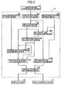
FIG. 2] FIG. 2 is a block diagram showing a circuit of an electronic control unit. (first embodiment) - [
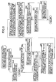
FIG. 3] FIG. 3 is a flowchart of a main routine. (first embodiment) - [
FIG. 4] FIG. 4 is a flowchart of a subroutine of step S2 of the main routine. (first embodiment) - [
FIG. 5) FIG. 5 is a flowchart of a subroutine of step S6 of the main routine. (first embodiment) - [
FIG. 6] FIG. 6 is a flowchart of a subroutine of step S5 of the main routine. (first embodiment) - [
FIG. 7] FIG. 7 is an explanatory diagram showing a distribution of reflection points within a processing region. (first embodiment) - [
FIG. 8] FIG. 8 is an explanatory diagram when a processing region on the side opposite to a parking space is narrowed. (first embodiment) - [
FIG. 9] FIG. 9 is an explanatory diagram for a method for setting a vehicle width direction boundary line. (first embodiment) - [
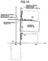
FIG. 10] FIG. 10 is an explanatory diagram for a method for setting a vehicle length direction boundary line on the far side of the parking space. (first embodiment) - [
FIG. 11] FIG. 11 is a diagram showing a map for carrying out determination of parking feasibility. (first embodiment) - [
FIG. 12] FIG. 12 is a diagram showing a parking feasible screen displayed on a display device. (first embodiment) - [
FIG. 13] FIG. 13 is a diagram showing a parking infeasible screen displayed on the display device. (first embodiment) -
- Ly
- Vehicle width direction boundary line
- Lx
- Vehicle length direction boundary line
- M1
- Reflection point detection means
- M2
- Reflection point storage means
- M3
- Processing region setting means
- M4
- Boundary line calculation means
- M5
- Intersection point calculation means
- M6
- Parking space existence determining means
- M7
- Parking space width calculation means
- M8
- Movable range calculation means
- M9
- Parking feasibility determining means
- P1
- First reflection point
- P2
- Second reflection point.
- P3
- Intersection point
- R
- Processing region
- Sp
- Parking space
- 11
- Radar device (transceiving means)
- A mode for carrying out the present invention is explained below by reference to the attached drawings.
- As shown in
FIG. 1 , a vehicular parking feasibility determining system of the present embodiment determines whether or not a parking space that a subject vehicle can be parked in is present by detecting, by means of aradar device 11 provided at the front end of the subject vehicle, an obstacle such as another vehicle or wall present in a region of 80° to each of the left and right, that is, a total of 160°, within a horizontal plane with the subject vehicle body axis as the center. In this example, there is a wall on the left side of a road where the subject vehicle stops, there are a plurality of other vehicles parking side by side on the right side, and a parking space Sp exists between the plurality of other vehicles. - An x-y rectangular coordinate system with the position of the
radar device 11 as the origin is fixed to the subject vehicle; its y axis coincides with the vehicle body axis, and its x axis is perpendicular to the y axis. Theradar device 11 scans an angular range of 160° in the horizontal direction by means of electromagnetic waves, and its resolution is 0.5°. Therefore, in an angular range of 160°, electromagnetic waves are transmitted to 321 directions, reflected waves thereof reflected from an object are received, and the x-y coordinates of reflection points of electromagnetic waves are thus detected. For example, inFIG. 1 , an object that is present in adirection 40° anticlockwise from the right end (0° direction) of the angular range of 160° is scanned by the 81st electromagnetic wave. Furthermore, there is a limit for the distance at which an object can be detected; for example, an object that is distant from theradar device 11 by 15 m or greater cannot be detected due to the intensity of the reflected waves being weakened. - As shown in
FIG. 2 , an electronic control unit U of the vehicular parking feasibility determining system has connected thereto, in addition to theradar device 11, adisplay device 12 and avoice guidance device 13. The electronic control unit U includes reflection point detection means M1, reflection point storage means M2, processing region setting means M3, boundary line calculation means M4, intersection point calculation means M5, parking space existence determining means M6, parking space width calculation means M7, movable range calculation means M8, and parking feasibility determining means M9, the reflection point detection means M1 having connected thereto theradar device 11, and the parking feasibility determining means M9 having connected thereto thedisplay device 12 and thevoice guidance device 13. - The operation of the vehicular parking feasibility determining system is now briefly explained by reference to a flowchart of a main routine shown in
FIG. 3 . - First, in step S1 the reflection point detection means M1 (see
FIG. 2 ) obtains reflection point data of obstacles based on detection results of theradar device 11. In the present embodiment, the obstacles are other vehicles parked side by side and a wall, and the reflection point data are given as x-y coordinates of reflection points at which electromagnetic waves transmitted toward the other vehicles parked side by side and the wall at intervals of 0.5° are reflected. - In the subsequent step S2 it is determined whether or not a sufficient amount of reflection point data for determining parking feasibility has been obtained from obstacles present on the right side of the subject vehicle that has stopped on the road, and it is determined by the parking space existence determining means M6 (see
FIG. 2 ) whether or not a parking space Sp in which the subject vehicle can be parked is present Even if it is determined by the parking space existence determining means M6 that a parking space Sp is present on the right side of the subject vehicle, since parking might be impossible in the parking space Sp when a width Wx of the road is narrow, even if the parking space Sp is present, parking therein is not always possible. - In the subsequent step S3 it is determined whether or not a sufficient amount of reflection point data for determining parking feasibility has been obtained from obstacles present on the left side of the subject vehicle that has stopped on the road, and it is determined by the parking space existence determining means M6 whether or not a space in which the subject vehicle can be parked is present The contents of step S3 are substantially the same as contents of step S2, the only difference being that processing (step S2) is based on the reflection point data on the right side of the subject vehicle body axis whereas processing (step S3) is based on the reflection point data on the left side of the subject vehicle body axis.
- In the subsequent step S4 the left side of a subject vehicle movable range, that is, the position of a boundary line on the left side of the width Wx of the road (this is defined as a left side vehicle width direction boundary line Ly), is calculated by the boundary line calculation means M4 (see
FIG. 2 ), and in step S5, of two angles on which the parking space Sp on the right side is in contact with the road, the coordinates of the corner that is distant from the subject vehicle (this is defined as an intersection point P3) are calculated by the intersection point calculation means M5 (seeFIG. 2 ), and a width Wy of the parking space Sp is thus calculated. - In the subsequent step S6 the right side of a subject vehicle movable range that is, the position of a boundary line on the right side of the width Wx of the road (this is defined as a right side vehicle width direction boundary line Ly), is calculated by the boundary line calculation means M4 (see
FIG. 2 ), and in step S7, of two corners at which the parking space Sp on the left side is in contact with the road, the coordinates of the corner that is distant from the subject vehicle (this is defined as the intersection point P3) are calculated by the intersection point calculation means M5 (seeFIG. 2 ), and the width Wy of the parking space Sp is thus calculated. - The contents of step S6 are substantially the same as contents of step S4, the only difference being that processing (step S4) is based on the reflection point data on the left side of the subject vehicle body axis whereas processing (step S6) is based on the reflection point data on the right side of the subject vehicle body axis. Furthermore, the contents of step S7 are substantially the same as contents of step S5, the only difference being that processing (step S5) is based on the reflection point data on the right side of the subject vehicle body axis whereas processing (step S7) is based on the reflection point data on the left side of the subject vehicle body axis.
-
FIG. 4 shows a subroutine of the above step S2 (detection of right side obstacle and existence of right side parking space); first, in step S21 each flag and each parameter are initialized, and in step S22 a distance disy_r in the y axis direction between two adjacent reflection points in a processing region on the right side of the subject vehicle body axis is calculated - That is, as shown in
FIG. 1 , a case is considered in which other vehicles are parked side by side on the right side of the subject vehicle with the parking space Sp interposed therebetween. In order to suppress the amount of data processed, inFIG. 7 the processing region setting means M3 (seeFIG. 2 ) sets a rectangular processing region R at a position where there is a high possibility of the parking space Sp being present In the embodiment, the processing region R is such that the x coordinate is in the range of 1 m to 5 m and the y coordinate is in the range of 0 m to 10 m. A plurality of + marks within the processing region R denote reflection points of electromagnetic waves from obstacles (the two other vehicles parked side by side), and all of the distances disy_r in the y axis direction of the two adjacent reflection points are calculated. - In the subsequent step S23, if a pair of reflection points for which the distance disy_r satisfies 2.5 m < disy_r 3.5 m is present, the parking space existence determining means M6 (see
FIG. 2 ) determines that a parking space Sp having a width of 2.5 m to 3.5 m in which side-by-side parking is possible is present between the two other vehicles parked side by side, and in step S24 a right side side-by-side parking flag is turned ON. Furthermore, in step S25 if a pair of reflection points for which the distance disy_r satisfies 6.5 < disy_r is present, the parking space existence determining means M6 determines that a parking space Sp having a width of greater than 6.5 m in which parallel parking is possible is present between two other vehicles that are parked side by side, and in step S26 a right side parallel parking flag is turned ON. - In step S27 a right side parking space detection flag is turned ON, and in step S28 among the two reflection points that satisfy the conditions of steps S23 and S25 above the coordinates of a first reflection point P1 are stored. As shown in
FIG. 7 , the first reflection point P1 corresponds to the front right corner of the other vehicle on the side close to the subject vehicle. In the subsequent step S29, among the two reflection points that satisfy the conditions of steps S23 and S25 above, the coordinates of a second reflection point P2 are stored. As shown inFIG. 7 , the second reflection point P2 corresponds to a point on the left side face of the other vehicle that is distant from the subject vehicle. - In the subsequent step S30 it is determined whether or not a sufficient number of reflection points for carrying out processing of steps S4 and S6 is present within the right side processing region R; if a sufficient number of reflection points is present then in step S31 a right side obstacle detection flag is turned ON, and if a sufficient number is not present then in step S32 the right side obstacle detection flag is turned OFF.
- The subroutine of step S2 above (right side obstacle and right side parking space existence detection) is explained above; a subroutine of step S3 above (left side obstacle and left side parking space existence detection) is substantially the same as that of step S2 above except that left and right are exchanged, and the explanation thereof is not repeated.
-
FIG. 5 shows a subroutine of step S6 above (movable range right side vehicle width direction boundary line calculation); first, if in step S41 the right side obstacle detection flag is not ON, then in step S42 a movable range right side boundary detection flag is turned OFF. In step S41 above, when the right side obstacle detection flag is ON, if in step S43 the left side parking space detection flag is ON, that is, a parking space Sp exists on the left side of the subject vehicle body axis, then in step S44 the range of the vehicle width direction boundary line detection is set in the range: y coordinate of first reflection point P1 < y < 10 m. - That is, in
FIG. 8 , a line that is parallel to the x axis on the side, close to the subject vehicle, of the processing region R on the right side is moved in a direction away to the position of the y coordinate of the first point P1 of the parking space Sp on the left side, thus making a correction in a direction so as to narrow the processing region R. The reason therefor is as follows. The right side vehicle width direction boundary line Ly is for determining whether or not the road width Wx is sufficient for carrying out parking; when the parking space Sp on the left side is established, since the feasibility of parking is not affected even if the width Wx of the road before reaching the y coordinate of the first reflection point P1 is narrow, the computational load is reduced by narrowing the processing region R, and determination is carried out more precisely from a truly necessary region. - On the other hand, if in step S43 above the left side parking space detection flag is not ON, that is, if there is no parking space Sp on the left side of the subject vehicle body axis, in step S45 the range of the vehicle width direction boundary line detection remains as a normal processing region R (see
FIG. 7 ). - In the subsequent step S46, as shown In
FIG. 9 , a large number of straight lines having a slope of 80° to 100° and an x-intercept of 1.0 m to 5.0 m within the right side processing region R (see broken lines) are calculated as candidates for the right side vehicle width direction boundary line Ly. The slope of the straight line is changed in, for example, steps of 1°, and the x-intercept of the straight line is changed in, for example, steps of 0.1 m. In the subsequent step S47 the distances Δx between each candidate for the vehicle width direction boundary line Ly and each reflection point are calculated and, following this, in step S48 the sum ΣΔx of the distances Δx is calculated and one straight line for which the sum ΣΔx becomes a minimum is determined as the right side vehicle width direction boundary line Ly. - If in the subsequent step S49. as shown in
FIG. 9 , a reflection point is present on the inside of the vehicle width direction boundary line Ly (the side close to the subject vehicle body axis), the vehicle width direction boundary line Ly is moved parallel in the x axis direction up to the position of a reflection point P4 that is on the innermost side, and this is determined as the final vehicle width direction boundary line Ly. The reason therefor is that if a reflection point (obstacle) is present on the inside of the vehicle width direction boundary line Ly, there is a possibility that parking in the parking space Sp will become impossible due to obstruction by the obstacle. - If in the subsequent step S50 the number of reflection points on the vehicle width direction boundary line Ly is a prescribed value or greater then in step S51 a movable range right side boundary detection flag is turned ON, and if the number is less than the prescribe value then in step S52 the movable range right side boundary detection flag is turned OFF.
- The subroutine of step S6 above (movable range right side vehicle width direction boundary line calculation) is explained above; a subroutine of step S4 above (movable range left side vehicle width direction boundary line calculation) is substantially the same as that of step S6 above except that left and right are exchanged, and the explanation thereof is not repeated.
-
FIG. 6 shows a subroutine of step S5 above (right side parking space coordinates calculation); first if in step S61 the right side parking space detection flag is not ON, then in step S62 a right side parking position FIX flag is turned OFF. When in step S61 above the right side parking space detection flag is ON, as shown inFIG. 10 , in step S63 a large number of straight lines (see broken lines) having a slope of -10° to 10° and passing through a range of ±0.5 m from the second reflection point P2 in the y axis direction are calculated as candidates for a right side vehicle length direction boundary line Lx. The slope of the straight line is changed in for example steps of 1°, and the position in the y axis direction of the straight line is changed in for example steps of 0.1 m. In the subsequent step S64 the distances Δy between each candidate for the vehicle length direction boundary line Lx and each reflection point are calculated and, following this, in step S65 the sum ΣΔy of the distances Δy is calculated and one straight line for which the sum ΣΔy becomes a minimum is determined as the vehicle length direction boundary line Lx on the far side of the parking space Sp. - If in the subsequent step S66 the number of reflection points on the vehicle length direction boundary line Lx is a prescribed value or greater then in step S67 a right side parking position FIX flag is turned ON, and if the number is less than the prescribed value then in step S68 the right side parking position FIX flag is turned OFF.
- In the subsequent step S69 the intersection point calculation means M5 (see
FIG. 2 ) calculates as right side parking position coordinates an intersection point P3 between the right side vehicle width direction boundary line Ly and the vehicle length direction boundary line Lx. - The subroutine of step S5 above (right side parking space coordinates calculation) is explained above; a subroutine of step S7 above (left side parking space coordinates calculation) is substantially the same as that of step S5 above except that left and right are exchanged, and the explanation thereof is not repeated.
- Returning to the flowchart of
FIG. 3 , in step S8 it is determined whether or not there is a parking space Sp on the right side or the left side of the subject vehicle. In steps S2 and S3 above it is determined that there is a parking space Sp when disy_r satisfies 2.5 m < disy_r < 3.5 m or 6.5 m < disy_r and, in addition thereto, the distance between the intersection point P3 and the second reflection point P2 in the x axis direction being a predetermined value or greater may be a necessary condition. The reason therefor is that if the distance between the intersection point P3 and the second reflection point P2 is short, when the subject vehicle is parked in the parking space Sp, there is a possibility that the front of the vehicle body of the subject vehicle will stick out from the parking space Sp into the road. - In the subsequent step S9 whether or not parking is possible in the parking space Sp is determined by the parking feasibility determining means M9 using a map of
FIG. 11 . This map employs as parameters the width Wy of the parking space Sp determined by the parking space width determining means M7 (seeFIG. 2 ) and the road width Wx (movable range) determined by the movable range determining means M8 (seeFIG. 2 ); the width Wy of the parking space Sp is calculated as the distance between the first reflection point P1 and the intersection point P3, and the road width Wx (movable range) is calculated as the minimum value for the distance between the right side vehicle width direction boundary line Ly and the left side vehicle width direction boundary line Ly. - In a region where the width Wy of the parking space Sp and the road width Wx are narrow, parking becomes impossible, and in a region where the width Wy of the parking space Sp and the road width Wx are wide, parking becomes feasible. Even in a region where parking is possible, the narrower the width Wy of the parking space Sp and the road width Wx, the larger the required number of repetitions of maneuvering back-and-forth; the upper limit for the number of repetitions of maneuvering back-and-forth is 5, and when the required number of repetitions of maneuvering back-and-forth is 6 or more, parking is defined as being infeasible.
- When parking is feasible, in step S10 the
display device 12 displays that parking is possible (seeFIG. 12 ) and, in addition, thevoice guidance device 13 notifies the result of parking being determined possible. When parking is impossible, in step S11 thedisplay device 12 displays that parking is infeasible (seeFIG. 13 ) and, in addition, the voice guidance device notifies the result of parking being determined infeasible. When an automatic parking start switch is turned ON in step S12 in the case of parking being feasible, in step S13 automatic parking in the parking space Sp is started. - . An embodiment of the present invention is explained above, but the present invention is not limited to the above-mentioned embodiment and may be modified in a variety of ways as long as the modifications do not depart from the scope thereof.
- For example, in the embodiment, when parking is determined as being feasible, automatic parking is carried out, but parking may be carried out by a manual operation.
Claims (6)
- A vehicular parking feasibility determining system comprising
transceiving means (11) that transmits electromagnetic waves so as to scan a predetermined angular range in the horizontal direction around a subject vehicle at predetermined time intervals, and receives reflected waves of the electromagnetic waves reflected from an object,
reflection point detection means (M1) that detects a reflection point at which electromagnetic waves are reflected from the object based on the result of reception of reflected waves by the transceiving means (11),
parking space existence determining means (M6) that determines the existence of a parking space (Sp) based on pre-stored subject vehicle body dimensional data and a sequence of the reflection points,
parking feasibility determining means (M9) that determines the feasibility of parking the subject vehicle from a current position thereof to the parking space (Sp), and
parking space width calculation means (M7) that calculates a width (Wy) of the parking space (Sp) in the subject vehicle length direction based on the sequence of reflection points,
the parking feasibility determining means (M9) determining the feasibility of parking based on the width (Wy) of the parking space (Sp),
characterized in that the system further comprises
movable range calculation means (M8) that calculates a movable range (Wx) in the subject vehicle width direction based on the sequence of reflection points, and
processing region setting means (M3) that sets a predetermined processing region (R) formed from a first range in the subject vehicle width direction and a second range in the subject vehicle length direction,
the parking feasibility determining means (M9) determining the feasibility of parking additionally based on the movable range (Wx), and
the parking space existence determining means (M6) determining that the parking space (Sp) exists when, among reflection points present within the processing region (R), a distance in the vehicle length direction between a pair of reflection points of the electromagnetic waves with adjacent angles in the horizontal direction is a predetermined value or greater. - The vehicular parking feasibility determining system according to Claim 1, wherein the system comprises
boundary line calculation means (M4) that calculates as a vehicle width direction boundary line (Ly) a straight line for which the sum of the distances in the vehicle width direction to the reflection points present within the processing region (R) is a minimum, and calculates as a vehicle length direction boundary line (Lx) a straight line for which the sum of the distances in the subject vehicle length direction therefrom is a minimum,
the movable range calculation means (M8) setting the processing region (R) on left and right with the subject vehicle body axis as the center, and calculating as a movable range (Wx) the minimum distance among the distances in the vehicle width direction of the left and right vehicle width direction boundary lines (Ly). - The vehicular parking feasibility determining system according to Claim 2, wherein the system comprises
reflection point storage means (M2) that, when the pair of reflection points is present within the processing region (R), stores as a first reflection point (P1) a reflection point for which, of the pair of reflection points, the distance from the subject vehicle in the vehicle length direction is near, and stores as a second reflection point (P2) a reflection point for which the distance is far,
the boundary line calculation means (M4) calculating, relative to the first reflection point (P1) stored in one of left and right processing regions (R), the vehicle width direction boundary line (Ly) within the other processing region (R) that is more distant in the vehicle length direction. - The vehicular parking feasibility determining system according to Claim 2 or Claim 3, wherein, when a reflection point is present on the subject vehicle body axis side relative to the vehicle width direction boundary line (Ly) within the left and right processing regions (R), the boundary line calculation means (M4) corrects the vehicle width direction boundary line (Ly) so as to pass through said reflection point.
- The vehicular parking feasibility determining system according to any one of Claim 2 to Claim 4, wherein, the system comprises
reflection point storage means (M2) that, when the pair of reflection points is present within the processing region (R), stores as a first reflection point (P1) a reflection point for which, of the pair of reflection points, the distance from the subject vehicle in the vehicle length direction is near, and stores as a second reflection point (P2) a reflection point for which it is far, and
intersection point calculation means (M5) that calculates an intersection point (P3) of the vehicle width direction boundary line (Ly) on the parking space (Sp) side with the vehicle length direction boundary line (Lx) calculated based on the second reflection point (P2),
the parking space width calculation means (M7) calculating a distance in the vehicle length direction between the first reflection point (P1) and the intersection point (P3) as the width (Wy) of the parking space (Sp). - The vehicular parking feasibility determining system according to Claim 5, wherein the parking space existence determining means (M6) determines that the parking space (Sp) exists when the distance in the vehicle width direction between the second reflection point (P2) and the intersection point (P3) is a predetermined value or greater.
Applications Claiming Priority (4)
| Application Number | Priority Date | Filing Date | Title |
|---|---|---|---|
| JP2007326396A JP4364923B2 (en) | 2007-12-18 | 2007-12-18 | Vehicle parking availability determination device |
| JP2007336592A JP4980875B2 (en) | 2007-12-27 | 2007-12-27 | Vehicle movable range detection device |
| JP2007336591A JP4980874B2 (en) | 2007-12-27 | 2007-12-27 | Parking space detection device for vehicles |
| PCT/JP2008/072652 WO2009078356A1 (en) | 2007-12-18 | 2008-12-12 | Parking availability judging device for vehicle, parking space detector for vehicle and movable range detector for vehicle |
Publications (3)
| Publication Number | Publication Date |
|---|---|
| EP2234085A1 EP2234085A1 (en) | 2010-09-29 |
| EP2234085A4 EP2234085A4 (en) | 2010-12-22 |
| EP2234085B1 true EP2234085B1 (en) | 2011-11-30 |
Family
ID=40795472
Family Applications (1)
| Application Number | Title | Priority Date | Filing Date |
|---|---|---|---|
| EP08862257A Not-in-force EP2234085B1 (en) | 2007-12-18 | 2008-12-12 | Parking availability judging device for vehicle |
Country Status (5)
| Country | Link |
|---|---|
| US (1) | US8560169B2 (en) |
| EP (1) | EP2234085B1 (en) |
| CN (1) | CN101878494B (en) |
| AT (1) | ATE535897T1 (en) |
| WO (1) | WO2009078356A1 (en) |
Families Citing this family (64)
| Publication number | Priority date | Publication date | Assignee | Title |
|---|---|---|---|---|
| DE102009027820A1 (en) * | 2009-07-20 | 2011-01-27 | Robert Bosch Gmbh | Device and method for assisted parking of a vehicle |
| DE102009040375A1 (en) * | 2009-09-07 | 2011-04-07 | Valeo Schalter Und Sensoren Gmbh | Method and device for supporting a parking process of a vehicle |
| DE102009047283A1 (en) * | 2009-11-30 | 2011-06-01 | Robert Bosch Gmbh | Method and device for assisting a driver of a motor vehicle |
| DE102010020208A1 (en) * | 2010-05-12 | 2011-11-17 | Volkswagen Ag | Method for parking or parking a vehicle and corresponding assistance system and vehicle |
| BR112012031582B1 (en) * | 2010-06-11 | 2020-02-18 | Nissan Motor Co., Ltd. | PARKING APPARATUS AND AID METHOD |
| DE102011003881A1 (en) * | 2011-02-09 | 2012-08-09 | Robert Bosch Gmbh | Method for assisting a driver of a motor vehicle |
| DE102011006939A1 (en) * | 2011-04-07 | 2012-10-11 | Robert Bosch Gmbh | Parking assistance system with side boundary detection |
| DE102011080930A1 (en) * | 2011-08-12 | 2013-02-14 | Robert Bosch Gmbh | Method and device for assisting a driver of a motor vehicle in a driving maneuver |
| WO2013049418A2 (en) * | 2011-09-27 | 2013-04-04 | Sensys Networks, Inc. | Position and/or distance measurement parking and/or vehicle detection, apparatus, networks, operations and/or systems |
| US8878697B2 (en) | 2011-10-19 | 2014-11-04 | Balu Subramanya | Directional speed and distance sensor |
| DE102011086245A1 (en) * | 2011-11-14 | 2013-05-16 | Robert Bosch Gmbh | Method for assisting a driver during a parking maneuver |
| CN102431551B (en) * | 2011-11-18 | 2014-06-11 | 奇瑞汽车股份有限公司 | Parking space detecting method and parking space detecting system |
| JP5918597B2 (en) * | 2012-04-04 | 2016-05-18 | 株式会社日本自動車部品総合研究所 | Parking space detector |
| JP5845131B2 (en) * | 2012-04-17 | 2016-01-20 | 株式会社日本自動車部品総合研究所 | Parking space detector |
| JP5660073B2 (en) * | 2012-04-19 | 2015-01-28 | トヨタ自動車株式会社 | Parking assistance device, parking assistance method, and parking assistance program |
| FR2994550B1 (en) * | 2012-08-14 | 2015-07-17 | Renault Sa | AUTOMATIC PARKING STRATEGY IN CRENEAU |
| CN103786662B (en) * | 2012-10-31 | 2016-06-15 | 上海博泰悦臻电子设备制造有限公司 | The generation method of reversing boost line and device |
| US11004337B2 (en) * | 2012-12-28 | 2021-05-11 | Balu Subramanya | Advanced parking management system |
| US8825292B2 (en) * | 2013-01-10 | 2014-09-02 | Ford Global Technologies, Llc | Suspension control system to facilitate wheel motions during parking |
| EP3690826A1 (en) * | 2013-03-15 | 2020-08-05 | Balu Subramanya | Advanced parking and intersection management system |
| CN106183992B (en) * | 2013-10-04 | 2019-03-15 | 本田技研工业株式会社 | Parking aid |
| KR101498973B1 (en) * | 2013-11-21 | 2015-03-05 | 현대모비스(주) | Parking asistance system and parking asistance method |
| US9291659B2 (en) * | 2013-12-19 | 2016-03-22 | Ford Global Technologies, Llc | Antenna blockage detection |
| DE102014212866A1 (en) * | 2014-07-02 | 2016-01-07 | Robert Bosch Gmbh | Method for determining a parking space from a number of measuring points |
| JP6062406B2 (en) * | 2014-09-12 | 2017-01-18 | アイシン精機株式会社 | Parking assistance device and parking assistance method |
| JP6500435B2 (en) * | 2014-12-26 | 2019-04-17 | アイシン精機株式会社 | Parking assistance device |
| DE102015201317A1 (en) * | 2015-01-27 | 2016-07-28 | Bayerische Motoren Werke Aktiengesellschaft | Measuring a dimension on a surface |
| US9542845B1 (en) * | 2015-09-11 | 2017-01-10 | Robert Bosch Gmbh | Method for ascertaining a parking area of a street section |
| CN106297375A (en) * | 2015-06-24 | 2017-01-04 | 奥迪股份公司 | For processing the system and method for information and being equipped with the vehicle of this system |
| DE102015212296A1 (en) * | 2015-07-01 | 2017-01-05 | Robert Bosch Gmbh | Method for determining a useful width of a road section |
| EP3330135B1 (en) * | 2015-07-29 | 2022-08-03 | Kyocera Corporation | Detection device, imaging device, vehicle, and detection method |
| JP6623602B2 (en) * | 2015-07-31 | 2019-12-25 | アイシン精機株式会社 | Parking assistance device |
| US10592756B2 (en) | 2015-09-11 | 2020-03-17 | Robert Bosch Gmbh | Method for detecting a parking area on a road section |
| DE102015116542A1 (en) * | 2015-09-30 | 2017-03-30 | Valeo Schalter Und Sensoren Gmbh | Method for determining a parking area for parking a motor vehicle, driver assistance system and motor vehicle |
| JP6555056B2 (en) * | 2015-09-30 | 2019-08-07 | アイシン精機株式会社 | Perimeter monitoring device |
| CN105353377B (en) * | 2015-09-30 | 2018-01-30 | 上海斐讯数据通信技术有限公司 | A kind of backing automobile radar monitoring device |
| JP6272582B2 (en) * | 2015-10-06 | 2018-01-31 | 三菱電機株式会社 | Parking type determination device |
| CA3002636C (en) * | 2015-10-22 | 2023-01-10 | Nissan Motor Co., Ltd. | Parking support information display method and parking support device |
| RU2691457C1 (en) * | 2015-10-22 | 2019-06-14 | Ниссан Мотор Ко., Лтд. | Parking assistance method and device |
| KR102121396B1 (en) * | 2015-10-22 | 2020-06-10 | 닛산 지도우샤 가부시키가이샤 | Parking Assistance Method and Parking Assistance Device |
| WO2017072955A1 (en) * | 2015-10-30 | 2017-05-04 | 三菱電機株式会社 | Parking assistance device and parking assistance method |
| MX368341B (en) * | 2015-12-17 | 2019-09-30 | Nissan Motor | Parking support method and device. |
| CN105741589B (en) * | 2016-03-25 | 2018-03-16 | 江苏大学 | A kind of parking space detection method and device based on truck traffic |
| CN105761533B (en) * | 2016-03-28 | 2018-06-29 | 江苏大学 | A kind of pilotless automobile parking stall planing method |
| JP6660595B2 (en) | 2016-06-07 | 2020-03-11 | パナソニックIpマネジメント株式会社 | Parking space search device, program and recording medium |
| CN105931491B (en) * | 2016-06-30 | 2019-06-28 | 深圳市金溢科技股份有限公司 | A kind of parking stall recognition methods, radar mould group and parking stall identifying system |
| GB2552487B (en) | 2016-07-25 | 2019-03-20 | Ford Global Tech Llc | Flow corridor detection and display system |
| JP6722066B2 (en) * | 2016-08-29 | 2020-07-15 | 株式会社Soken | Surrounding monitoring device and surrounding monitoring method |
| US11393340B2 (en) * | 2016-12-30 | 2022-07-19 | Hyundai Motor Company | Automatic parking system and automatic parking method |
| WO2018134915A1 (en) * | 2017-01-18 | 2018-07-26 | 三菱電機株式会社 | Parking assistance device |
| EP3401699A1 (en) * | 2017-05-09 | 2018-11-14 | Veoneer Sweden AB | Vehicle environmental detection system for parking detection |
| KR102429494B1 (en) * | 2017-10-13 | 2022-08-05 | 현대자동차주식회사 | Apparatus for displaying target parking space of vehicle and method thereof |
| CN108254752B (en) * | 2017-12-20 | 2020-03-27 | 广州汽车集团股份有限公司 | Method and device for detecting inclined parking spaces and automatic parking method and system |
| JP2019174975A (en) * | 2018-03-27 | 2019-10-10 | パナソニックIpマネジメント株式会社 | Identification device, identification method, identification program, and non-transitory tangible recording medium having identification program recorded therein |
| US10997860B2 (en) * | 2018-03-30 | 2021-05-04 | Hitachi Automotive Systems, Ltd. | Parking assistance device |
| KR20200046160A (en) | 2018-10-16 | 2020-05-07 | 현대자동차주식회사 | Autonomous parking apparatus and method |
| CN111127938A (en) * | 2018-10-30 | 2020-05-08 | 长城汽车股份有限公司 | Vehicle safety early warning method and system and vehicle |
| CN111402590B (en) * | 2019-01-03 | 2021-09-21 | 杭州海康威视系统技术有限公司 | Parking guidance method, device, vehicle-mounted unit, center server and system |
| CN109927715B (en) * | 2019-02-19 | 2020-08-25 | 惠州市德赛西威智能交通技术研究院有限公司 | Vertical parking method |
| CN110956847B (en) * | 2019-12-20 | 2021-11-30 | 奇瑞汽车股份有限公司 | Parking space identification method and device and storage medium |
| CN112349133B (en) * | 2020-07-20 | 2022-11-04 | 北京筑梦园科技有限公司 | Management method, server and parking management system for irregular parking |
| DE102021202006A1 (en) | 2021-03-02 | 2022-09-08 | Volkswagen Aktiengesellschaft | Method for searching for a parking space for a motor vehicle and motor vehicle |
| US11938928B2 (en) * | 2021-11-03 | 2024-03-26 | Honda Motor Co., Ltd. | Systems and methods for vehicular navigation of narrow gaps |
| DE102022104437A1 (en) * | 2022-02-24 | 2023-08-24 | Bayerische Motoren Werke Aktiengesellschaft | Method and vehicle guidance system for parking a vehicle in a perpendicular parking space |
Family Cites Families (21)
| Publication number | Priority date | Publication date | Assignee | Title |
|---|---|---|---|---|
| US4931930A (en) * | 1988-04-19 | 1990-06-05 | Industrial Technology Research Institute | Automatic parking device for automobile |
| JP3052563B2 (en) | 1992-04-24 | 2000-06-12 | 株式会社デンソー | Vehicle target position guidance device |
| JP3362584B2 (en) | 1995-12-22 | 2003-01-07 | 三菱自動車工業株式会社 | Parking judgment device |
| JP2952816B2 (en) * | 1996-12-17 | 1999-09-27 | 本田技研工業株式会社 | Automatic vehicle steering system |
| JP3183284B2 (en) * | 1999-01-19 | 2001-07-09 | 株式会社豊田自動織機製作所 | Steering support device for reversing a vehicle |
| JP2002154396A (en) | 2000-11-22 | 2002-05-28 | Nissan Motor Co Ltd | Parking support device for vehicle |
| JP2002243857A (en) | 2001-02-14 | 2002-08-28 | Nissan Motor Co Ltd | Surrounding body recognizer |
| JP4161573B2 (en) * | 2001-06-29 | 2008-10-08 | 株式会社豊田自動織機 | Parking assistance device |
| JP2003048500A (en) * | 2001-08-02 | 2003-02-18 | Equos Research Co Ltd | Device for supporting parking operation |
| DE10146712A1 (en) * | 2001-09-21 | 2003-04-10 | Bayerische Motoren Werke Ag | Parking aid device for motor vehicles |
| DE10206764A1 (en) * | 2002-02-19 | 2003-08-28 | Bosch Gmbh Robert | Method for parking a motor vehicle in which a number of distance sensors are used to detect the positions of obstacles, and thus determine the width and length of a gap before checking minimum separations during final parking |
| JP4700899B2 (en) | 2003-04-14 | 2011-06-15 | 株式会社豊田自動織機 | Parking assistance device |
| US6970101B1 (en) * | 2003-04-21 | 2005-11-29 | James C Squire | Parking guidance method and system |
| DE10324812A1 (en) * | 2003-06-02 | 2004-12-23 | Robert Bosch Gmbh | Display arrangement for a motor vehicle and method for outputting driver information, in particular for a parking aid |
| DE102004001428A1 (en) * | 2004-01-09 | 2005-08-04 | Robert Bosch Gmbh | Method for driver assistance systems for improving the parking starting position |
| JP4461920B2 (en) * | 2004-06-23 | 2010-05-12 | 株式会社デンソー | Parking assistance device |
| JP4179285B2 (en) * | 2005-01-12 | 2008-11-12 | トヨタ自動車株式会社 | Parking assistance device |
| JP4654856B2 (en) | 2005-04-06 | 2011-03-23 | 日産自動車株式会社 | Parking assistance device and parking assistance method |
| US7312722B2 (en) * | 2005-05-09 | 2007-12-25 | The Boeing Company | System and method for assessing parking space occupancy and for reserving same |
| JP4741394B2 (en) * | 2006-03-30 | 2011-08-03 | 株式会社トヨタマップマスター | Parking assistance system |
| US7653487B2 (en) * | 2006-10-06 | 2010-01-26 | Toyota Motor Engineering & Manufacturing North America, Inc. | Object detection apparatus and method |
-
2008
- 2008-12-12 WO PCT/JP2008/072652 patent/WO2009078356A1/en active Application Filing
- 2008-12-12 US US12/745,864 patent/US8560169B2/en not_active Expired - Fee Related
- 2008-12-12 EP EP08862257A patent/EP2234085B1/en not_active Not-in-force
- 2008-12-12 CN CN2008801181878A patent/CN101878494B/en not_active Expired - Fee Related
- 2008-12-12 AT AT08862257T patent/ATE535897T1/en active
Also Published As
| Publication number | Publication date |
|---|---|
| WO2009078356A1 (en) | 2009-06-25 |
| CN101878494B (en) | 2013-06-26 |
| US20100274446A1 (en) | 2010-10-28 |
| EP2234085A4 (en) | 2010-12-22 |
| US8560169B2 (en) | 2013-10-15 |
| CN101878494A (en) | 2010-11-03 |
| ATE535897T1 (en) | 2011-12-15 |
| EP2234085A1 (en) | 2010-09-29 |
Similar Documents
| Publication | Publication Date | Title |
|---|---|---|
| EP2234085B1 (en) | Parking availability judging device for vehicle | |
| CN107241916B (en) | Vehicle travel control device and travel control method | |
| US10486698B2 (en) | Vehicle cruise control device and cruise control method | |
| JP4364923B2 (en) | Vehicle parking availability determination device | |
| US8410919B2 (en) | Driving support apparatus | |
| US20050271253A1 (en) | Target detection system using radar and image processing | |
| JPH06230115A (en) | Vehicular gap detector | |
| CN111066071A (en) | Position error correction method and position error correction device for driving assistance vehicle | |
| JP2011118482A (en) | In-vehicle device and recognition support system | |
| KR20150012799A (en) | Apparatus and method for providing parking control | |
| WO2014125810A1 (en) | Obstruction detection device | |
| JP2009014479A (en) | Object detection device for vehicle | |
| CN110865640B (en) | Obstacle avoidance structure of intelligent robot | |
| JP2014094725A (en) | Parking support device | |
| CN112415502A (en) | Radar apparatus | |
| JP4980874B2 (en) | Parking space detection device for vehicles | |
| JP4980875B2 (en) | Vehicle movable range detection device | |
| JPH09218265A (en) | Apparatus for automatically correcting center axis of radar | |
| JP4850531B2 (en) | In-vehicle radar system | |
| JP2009286355A (en) | Parking assisting apparatus, parking assisting method, and computer program | |
| JP2000207697A (en) | Device for monitoring periphery of vehicle | |
| JP2021043164A (en) | Object detector and object detection method | |
| JP2005199910A (en) | Vehicular mirror control device and vehicular mirror control method | |
| JP4644590B2 (en) | Peripheral vehicle position detection device and peripheral vehicle position detection method | |
| CN115649167A (en) | Vehicle lane change determining method and device, electronic equipment and storage medium |
Legal Events
| Date | Code | Title | Description |
|---|---|---|---|
| PUAI | Public reference made under article 153(3) epc to a published international application that has entered the european phase |
Free format text: ORIGINAL CODE: 0009012 |
|
| 17P | Request for examination filed |
Effective date: 20100528 |
|
| AK | Designated contracting states |
Kind code of ref document: A1 Designated state(s): AT BE BG CH CY CZ DE DK EE ES FI FR GB GR HR HU IE IS IT LI LT LU LV MC MT NL NO PL PT RO SE SI SK TR |
|
| AX | Request for extension of the european patent |
Extension state: AL BA MK RS |
|
| A4 | Supplementary search report drawn up and despatched |
Effective date: 20101124 |
|
| RIC1 | Information provided on ipc code assigned before grant |
Ipc: B62D 15/02 20060101ALI20101118BHEP Ipc: G08G 1/16 20060101AFI20101118BHEP Ipc: G01S 13/93 20060101ALN20101118BHEP Ipc: G08G 1/14 20060101ALN20101118BHEP |
|
| 17Q | First examination report despatched |
Effective date: 20101221 |
|
| DAX | Request for extension of the european patent (deleted) | ||
| REG | Reference to a national code |
Ref country code: DE Ref legal event code: R079 Ref document number: 602008011783 Country of ref document: DE Free format text: PREVIOUS MAIN CLASS: G08G0001140000 Ipc: G08G0001160000 |
|
| GRAP | Despatch of communication of intention to grant a patent |
Free format text: ORIGINAL CODE: EPIDOSNIGR1 |
|
| RIC1 | Information provided on ipc code assigned before grant |
Ipc: G01S 13/93 20060101ALN20110511BHEP Ipc: B62D 15/02 20060101ALI20110511BHEP Ipc: G08G 1/14 20060101ALN20110511BHEP Ipc: G08G 1/16 20060101AFI20110511BHEP |
|
| RTI1 | Title (correction) |
Free format text: PARKING AVAILABILITY JUDGING DEVICE FOR VEHICLE |
|
| RTI1 | Title (correction) |
Free format text: PARKING AVAILABILITY JUDGING DEVICE FOR VEHICLE |
|
| GRAS | Grant fee paid |
Free format text: ORIGINAL CODE: EPIDOSNIGR3 |
|
| GRAA | (expected) grant |
Free format text: ORIGINAL CODE: 0009210 |
|
| AK | Designated contracting states |
Kind code of ref document: B1 Designated state(s): AT BE BG CH CY CZ DE DK EE ES FI FR GB GR HR HU IE IS IT LI LT LU LV MC MT NL NO PL PT RO SE SI SK TR |
|
| REG | Reference to a national code |
Ref country code: GB Ref legal event code: FG4D Ref country code: CH Ref legal event code: EP |
|
| REG | Reference to a national code |
Ref country code: IE Ref legal event code: FG4D |
|
| REG | Reference to a national code |
Ref country code: DE Ref legal event code: R096 Ref document number: 602008011783 Country of ref document: DE Effective date: 20120216 |
|
| REG | Reference to a national code |
Ref country code: NL Ref legal event code: VDEP Effective date: 20111130 |
|
| LTIE | Lt: invalidation of european patent or patent extension |
Effective date: 20111130 |
|
| PG25 | Lapsed in a contracting state [announced via postgrant information from national office to epo] |
Ref country code: LT Free format text: LAPSE BECAUSE OF FAILURE TO SUBMIT A TRANSLATION OF THE DESCRIPTION OR TO PAY THE FEE WITHIN THE PRESCRIBED TIME-LIMIT Effective date: 20111130 Ref country code: NO Free format text: LAPSE BECAUSE OF FAILURE TO SUBMIT A TRANSLATION OF THE DESCRIPTION OR TO PAY THE FEE WITHIN THE PRESCRIBED TIME-LIMIT Effective date: 20120229 Ref country code: IS Free format text: LAPSE BECAUSE OF FAILURE TO SUBMIT A TRANSLATION OF THE DESCRIPTION OR TO PAY THE FEE WITHIN THE PRESCRIBED TIME-LIMIT Effective date: 20120330 |
|
| PG25 | Lapsed in a contracting state [announced via postgrant information from national office to epo] |
Ref country code: SI Free format text: LAPSE BECAUSE OF FAILURE TO SUBMIT A TRANSLATION OF THE DESCRIPTION OR TO PAY THE FEE WITHIN THE PRESCRIBED TIME-LIMIT Effective date: 20111130 Ref country code: HR Free format text: LAPSE BECAUSE OF FAILURE TO SUBMIT A TRANSLATION OF THE DESCRIPTION OR TO PAY THE FEE WITHIN THE PRESCRIBED TIME-LIMIT Effective date: 20111130 Ref country code: LV Free format text: LAPSE BECAUSE OF FAILURE TO SUBMIT A TRANSLATION OF THE DESCRIPTION OR TO PAY THE FEE WITHIN THE PRESCRIBED TIME-LIMIT Effective date: 20111130 Ref country code: BE Free format text: LAPSE BECAUSE OF FAILURE TO SUBMIT A TRANSLATION OF THE DESCRIPTION OR TO PAY THE FEE WITHIN THE PRESCRIBED TIME-LIMIT Effective date: 20111130 Ref country code: NL Free format text: LAPSE BECAUSE OF FAILURE TO SUBMIT A TRANSLATION OF THE DESCRIPTION OR TO PAY THE FEE WITHIN THE PRESCRIBED TIME-LIMIT Effective date: 20111130 Ref country code: PT Free format text: LAPSE BECAUSE OF FAILURE TO SUBMIT A TRANSLATION OF THE DESCRIPTION OR TO PAY THE FEE WITHIN THE PRESCRIBED TIME-LIMIT Effective date: 20120330 Ref country code: SE Free format text: LAPSE BECAUSE OF FAILURE TO SUBMIT A TRANSLATION OF THE DESCRIPTION OR TO PAY THE FEE WITHIN THE PRESCRIBED TIME-LIMIT Effective date: 20111130 Ref country code: GR Free format text: LAPSE BECAUSE OF FAILURE TO SUBMIT A TRANSLATION OF THE DESCRIPTION OR TO PAY THE FEE WITHIN THE PRESCRIBED TIME-LIMIT Effective date: 20120301 |
|
| PG25 | Lapsed in a contracting state [announced via postgrant information from national office to epo] |
Ref country code: CY Free format text: LAPSE BECAUSE OF FAILURE TO SUBMIT A TRANSLATION OF THE DESCRIPTION OR TO PAY THE FEE WITHIN THE PRESCRIBED TIME-LIMIT Effective date: 20111130 |
|
| PG25 | Lapsed in a contracting state [announced via postgrant information from national office to epo] |
Ref country code: CZ Free format text: LAPSE BECAUSE OF FAILURE TO SUBMIT A TRANSLATION OF THE DESCRIPTION OR TO PAY THE FEE WITHIN THE PRESCRIBED TIME-LIMIT Effective date: 20111130 Ref country code: MC Free format text: LAPSE BECAUSE OF NON-PAYMENT OF DUE FEES Effective date: 20111231 Ref country code: EE Free format text: LAPSE BECAUSE OF FAILURE TO SUBMIT A TRANSLATION OF THE DESCRIPTION OR TO PAY THE FEE WITHIN THE PRESCRIBED TIME-LIMIT Effective date: 20111130 Ref country code: SK Free format text: LAPSE BECAUSE OF FAILURE TO SUBMIT A TRANSLATION OF THE DESCRIPTION OR TO PAY THE FEE WITHIN THE PRESCRIBED TIME-LIMIT Effective date: 20111130 Ref country code: BG Free format text: LAPSE BECAUSE OF FAILURE TO SUBMIT A TRANSLATION OF THE DESCRIPTION OR TO PAY THE FEE WITHIN THE PRESCRIBED TIME-LIMIT Effective date: 20120229 Ref country code: DK Free format text: LAPSE BECAUSE OF FAILURE TO SUBMIT A TRANSLATION OF THE DESCRIPTION OR TO PAY THE FEE WITHIN THE PRESCRIBED TIME-LIMIT Effective date: 20111130 |
|
| PG25 | Lapsed in a contracting state [announced via postgrant information from national office to epo] |
Ref country code: IT Free format text: LAPSE BECAUSE OF FAILURE TO SUBMIT A TRANSLATION OF THE DESCRIPTION OR TO PAY THE FEE WITHIN THE PRESCRIBED TIME-LIMIT Effective date: 20111130 Ref country code: PL Free format text: LAPSE BECAUSE OF FAILURE TO SUBMIT A TRANSLATION OF THE DESCRIPTION OR TO PAY THE FEE WITHIN THE PRESCRIBED TIME-LIMIT Effective date: 20111130 Ref country code: RO Free format text: LAPSE BECAUSE OF FAILURE TO SUBMIT A TRANSLATION OF THE DESCRIPTION OR TO PAY THE FEE WITHIN THE PRESCRIBED TIME-LIMIT Effective date: 20111130 |
|
| REG | Reference to a national code |
Ref country code: AT Ref legal event code: MK05 Ref document number: 535897 Country of ref document: AT Kind code of ref document: T Effective date: 20111130 |
|
| REG | Reference to a national code |
Ref country code: IE Ref legal event code: MM4A |
|
| PLBE | No opposition filed within time limit |
Free format text: ORIGINAL CODE: 0009261 |
|
| STAA | Information on the status of an ep patent application or granted ep patent |
Free format text: STATUS: NO OPPOSITION FILED WITHIN TIME LIMIT |
|
| PG25 | Lapsed in a contracting state [announced via postgrant information from national office to epo] |
Ref country code: IE Free format text: LAPSE BECAUSE OF NON-PAYMENT OF DUE FEES Effective date: 20111212 |
|
| 26N | No opposition filed |
Effective date: 20120831 |
|
| REG | Reference to a national code |
Ref country code: DE Ref legal event code: R097 Ref document number: 602008011783 Country of ref document: DE Effective date: 20120831 |
|
| PG25 | Lapsed in a contracting state [announced via postgrant information from national office to epo] |
Ref country code: AT Free format text: LAPSE BECAUSE OF FAILURE TO SUBMIT A TRANSLATION OF THE DESCRIPTION OR TO PAY THE FEE WITHIN THE PRESCRIBED TIME-LIMIT Effective date: 20111130 |
|
| PG25 | Lapsed in a contracting state [announced via postgrant information from national office to epo] |
Ref country code: MT Free format text: LAPSE BECAUSE OF FAILURE TO SUBMIT A TRANSLATION OF THE DESCRIPTION OR TO PAY THE FEE WITHIN THE PRESCRIBED TIME-LIMIT Effective date: 20111130 |
|
| PG25 | Lapsed in a contracting state [announced via postgrant information from national office to epo] |
Ref country code: ES Free format text: LAPSE BECAUSE OF FAILURE TO SUBMIT A TRANSLATION OF THE DESCRIPTION OR TO PAY THE FEE WITHIN THE PRESCRIBED TIME-LIMIT Effective date: 20120311 |
|
| PG25 | Lapsed in a contracting state [announced via postgrant information from national office to epo] |
Ref country code: LU Free format text: LAPSE BECAUSE OF NON-PAYMENT OF DUE FEES Effective date: 20111212 |
|
| PG25 | Lapsed in a contracting state [announced via postgrant information from national office to epo] |
Ref country code: FI Free format text: LAPSE BECAUSE OF FAILURE TO SUBMIT A TRANSLATION OF THE DESCRIPTION OR TO PAY THE FEE WITHIN THE PRESCRIBED TIME-LIMIT Effective date: 20111130 |
|
| REG | Reference to a national code |
Ref country code: CH Ref legal event code: PL |
|
| GBPC | Gb: european patent ceased through non-payment of renewal fee |
Effective date: 20121212 |
|
| PG25 | Lapsed in a contracting state [announced via postgrant information from national office to epo] |
Ref country code: TR Free format text: LAPSE BECAUSE OF FAILURE TO SUBMIT A TRANSLATION OF THE DESCRIPTION OR TO PAY THE FEE WITHIN THE PRESCRIBED TIME-LIMIT Effective date: 20111130 |
|
| PG25 | Lapsed in a contracting state [announced via postgrant information from national office to epo] |
Ref country code: CH Free format text: LAPSE BECAUSE OF NON-PAYMENT OF DUE FEES Effective date: 20121231 Ref country code: LI Free format text: LAPSE BECAUSE OF NON-PAYMENT OF DUE FEES Effective date: 20121231 Ref country code: HU Free format text: LAPSE BECAUSE OF FAILURE TO SUBMIT A TRANSLATION OF THE DESCRIPTION OR TO PAY THE FEE WITHIN THE PRESCRIBED TIME-LIMIT Effective date: 20111130 |
|
| PG25 | Lapsed in a contracting state [announced via postgrant information from national office to epo] |
Ref country code: GB Free format text: LAPSE BECAUSE OF NON-PAYMENT OF DUE FEES Effective date: 20121212 |
|
| PGFP | Annual fee paid to national office [announced via postgrant information from national office to epo] |
Ref country code: DE Payment date: 20131204 Year of fee payment: 6 |
|
| PGFP | Annual fee paid to national office [announced via postgrant information from national office to epo] |
Ref country code: FR Payment date: 20131209 Year of fee payment: 6 |
|
| REG | Reference to a national code |
Ref country code: DE Ref legal event code: R119 Ref document number: 602008011783 Country of ref document: DE |
|
| REG | Reference to a national code |
Ref country code: FR Ref legal event code: ST Effective date: 20150831 |
|
| PG25 | Lapsed in a contracting state [announced via postgrant information from national office to epo] |
Ref country code: DE Free format text: LAPSE BECAUSE OF NON-PAYMENT OF DUE FEES Effective date: 20150701 |
|
| PG25 | Lapsed in a contracting state [announced via postgrant information from national office to epo] |
Ref country code: FR Free format text: LAPSE BECAUSE OF NON-PAYMENT OF DUE FEES Effective date: 20141231 |