EP2233718A1 - Turbocharger - Google Patents
Turbocharger Download PDFInfo
- Publication number
- EP2233718A1 EP2233718A1 EP08859176A EP08859176A EP2233718A1 EP 2233718 A1 EP2233718 A1 EP 2233718A1 EP 08859176 A EP08859176 A EP 08859176A EP 08859176 A EP08859176 A EP 08859176A EP 2233718 A1 EP2233718 A1 EP 2233718A1
- Authority
- EP
- European Patent Office
- Prior art keywords
- vane
- nozzle
- turbine
- turbocharger
- nozzle vanes
- Prior art date
- Legal status (The legal status is an assumption and is not a legal conclusion. Google has not performed a legal analysis and makes no representation as to the accuracy of the status listed.)
- Granted
Links
Images






Classifications
-
- F—MECHANICAL ENGINEERING; LIGHTING; HEATING; WEAPONS; BLASTING
- F01—MACHINES OR ENGINES IN GENERAL; ENGINE PLANTS IN GENERAL; STEAM ENGINES
- F01D—NON-POSITIVE DISPLACEMENT MACHINES OR ENGINES, e.g. STEAM TURBINES
- F01D17/00—Regulating or controlling by varying flow
- F01D17/10—Final actuators
- F01D17/12—Final actuators arranged in stator parts
- F01D17/14—Final actuators arranged in stator parts varying effective cross-sectional area of nozzles or guide conduits
- F01D17/16—Final actuators arranged in stator parts varying effective cross-sectional area of nozzles or guide conduits by means of nozzle vanes
- F01D17/165—Final actuators arranged in stator parts varying effective cross-sectional area of nozzles or guide conduits by means of nozzle vanes for radial flow, i.e. the vanes turning around axes which are essentially parallel to the rotor centre line
-
- F—MECHANICAL ENGINEERING; LIGHTING; HEATING; WEAPONS; BLASTING
- F02—COMBUSTION ENGINES; HOT-GAS OR COMBUSTION-PRODUCT ENGINE PLANTS
- F02B—INTERNAL-COMBUSTION PISTON ENGINES; COMBUSTION ENGINES IN GENERAL
- F02B37/00—Engines characterised by provision of pumps driven at least for part of the time by exhaust
- F02B37/12—Control of the pumps
- F02B37/24—Control of the pumps by using pumps or turbines with adjustable guide vanes
-
- F—MECHANICAL ENGINEERING; LIGHTING; HEATING; WEAPONS; BLASTING
- F05—INDEXING SCHEMES RELATING TO ENGINES OR PUMPS IN VARIOUS SUBCLASSES OF CLASSES F01-F04
- F05D—INDEXING SCHEME FOR ASPECTS RELATING TO NON-POSITIVE-DISPLACEMENT MACHINES OR ENGINES, GAS-TURBINES OR JET-PROPULSION PLANTS
- F05D2220/00—Application
- F05D2220/40—Application in turbochargers
-
- Y—GENERAL TAGGING OF NEW TECHNOLOGICAL DEVELOPMENTS; GENERAL TAGGING OF CROSS-SECTIONAL TECHNOLOGIES SPANNING OVER SEVERAL SECTIONS OF THE IPC; TECHNICAL SUBJECTS COVERED BY FORMER USPC CROSS-REFERENCE ART COLLECTIONS [XRACs] AND DIGESTS
- Y02—TECHNOLOGIES OR APPLICATIONS FOR MITIGATION OR ADAPTATION AGAINST CLIMATE CHANGE
- Y02T—CLIMATE CHANGE MITIGATION TECHNOLOGIES RELATED TO TRANSPORTATION
- Y02T10/00—Road transport of goods or passengers
- Y02T10/10—Internal combustion engine [ICE] based vehicles
- Y02T10/12—Improving ICE efficiencies
Definitions
- the present invention relates to a turbocharger which is simple in structure and which can reduce turbulence of fluid in a turbine impeller outlet to improve efficiency of a turbine.
- Fig. 1 shows a conventional variable displacement turbocharger to which the invention is applied.
- turbine and compressor housings 1 and 2 are integrally assembled through a bearing housing 3 by fastening bolts 3a and 3b, a turbine impeller 4 in the turbine housing 1 being connected to a compressor impeller 5 in the compressor housing 2 by a turbine shaft 7 rotatably supported via a bearing 6 in the bearing housing 3.
- the bearing housing 3 is provided, on its turbine housing 1 side, with an exhaust nozzle 9 by which fluid (exhaust gas) introduced into a scroll passage 8 in the turbine housing 1 is guided to a turbine impeller 4.
- the exhaust nozzle 9 comprises front and rear exhaust introduction walls 10 and 11 respectively on sides of the bearing and turbine housings 3 and 1 and integrally assembled together with a required distance between them by, for example, three fixing members 12 arranged circumferentially.
- an attachment member 13 fixed on a front surface of the front wall 10 (side surface of the bearing housing 3) is clamped by the housings 1 and 3 to fix the exhaust nozzle 9.
- the exhaust nozzle 9 is positioned with respect to the bearing housing 3 by a positioning pin 14.
- each of the nozzle vanes 15 is supported in a cantilever manner by the vane shaft 16 arranged on the vane 15 on the side of the bearing housing 3 to extend through the front wall 10.
- each of the nozzle vanes 15 may be dually supported by vane shafts 16 and 28 on opposite sides of the vane 15 extending through the front and rear walls 10 and 11, respectively.
- reference numerals 17a, 17b, 17c and 17d designate a linked transmission mechanism for varying an opening angle of the nozzle vanes 15 for capacity control; and 18, a scroll passage in the compressor housing 2.
- a gap 19 which is, by nature, is unwanted and which is however is provided for countermeasure to, for example, possible thermal deformation of the turbine housing 1 between during being hot and during being cold and possible variations in accuracy of parts to be assembled.
- the gap 19 may disadvantageously cause the exhaust gas in the scroll passage 8 to vainly leak to a turbine impeller outlet 20, resulting in lowering of turbine efficiency.
- sealing piston rings 21 between an outer surface of a downstream extension 11' of the rear wall 11 and an inner surface 1' of the turbine housing 1 confronting the extension 11' so as to prevent the gas leakage and absorb thermal deformation (see Patent Literature 1).
- Patent Literature 1 As best shown in Fig. 2 , formed on the outer periphery of the extension 11' of the rear wall 11 is an annular groove 22 into which generally two sealing piston rings 21 are inserted with their closed gaps being not aligned or overlapped with each other, thereby providing a sealing device.
- the piston rings 21 are pressed at their outer peripheries against the inner surface 1' of the turbine housing 1 by spring force of the piston rings themselves to prevent the gas leakage.
- the inventors have made various researches and experiments on factors other than the gas leakage affecting the turbine efficiency to find out that the more the exhaust gas in the turbine impeller outlet 20 is turbulent, the more the turbine efficiency is lowered and that the less the exhaust gas in the turbine impeller outlet 20 is turbulent, the more the turbine efficiency is improved.
- the invention was made in view of the above and has its object to provide a turbocharger which is simple in structure and which can reduce turbulence of fluid in a turbine impeller outlet to improve turbine efficiency.
- the invention is directed to a turbocharger with a turbine housing having a scroll passage outwardly of an exhaust nozzle which in turn is arranged outwardly of a turbine impeller rotatably supported on a bearing housing, said exhaust nozzle having a plurality of nozzle vanes between front and rear exhaust introduction walls on sides of the bearing and turbine housings, respectively, a vane shaft for each of said nozzle vanes extending at least through the front wall and being rotatably supported, characterized in that it comprises pressing means arranged between the respective vane shafts and the bearing housing for urging the respective vane shafts toward the rear wall to displace the nozzle vanes toward the rear wall.
- said pressing means may be a disc spring between the vane shafts and the bearing housing.
- said pressing means may be a coiled spring between each of the vane shafts and the bearing housing.
- each of said nozzle vanes may be supported in a cantilever manner by the vane shaft on one side of the vane extending through the front wall.
- each of said nozzle vane may be dually supported by vane shafts on opposite sides of the vane extending through the front and rear walls, respectively.
- each of said nozzle vane may be dually supported by vane shafts on opposite sides of the vane, one of the vane shafts extending through the front wall, the other of the vane shafts being embedded in the rear wall.
- a clearance between the nozzle vanes and the rear wall can be minimized by the simple structure, resulting in advantageous effect that turbulence of the fluid in the turbine impeller outlet can be reduced to substantially improve efficiency of the turbine.
- FIG. 3 shows an embodiment of the invention applied to the turbocharger shown in Fig. 2 with nozzle vanes 15 being arranged between front and rear exhaust introduction walls 10 and 11 of an exhaust nozzle 9 and each being supported in a cantilever manner by a vane shaft 16 arranged on a side of the vane 15 and extending through the front wall 10, comprising pressing means 23 arranged between a front end 16' (right end in Fig.
- the pressing means 23 shown in Fig. 3 is in the form of a disc spring 24 which urges the respective vane shafts 16 toward the rear wall 11.
- the disc spring 24 is frustconical and has inner and outer peripheral edges 25 and 26 mutually offset with respect to an axis of the spring to thereby provide a doughnut shape, an axial height H of the disc spring 24 with the frustconical shape being set to be greater than a distance between the respective front ends 16' of the respective vane shafts 16 and the rear surface 3' of the bearing housing 3.
- the respective front ends 16' of the vane shafts 16 extend through and are retained by inner ends of nozzle link plates 16a (shaft support members) arranged between the front wall 10 and the rear surface 3' of the bearing housing 3.
- the respective nozzle link plates 16a are pivoted about the vane shafts 16 by rotating a drive ring (not shown); the respective vane shafts 16 (nozzle vanes 15) are rotated integrally with the respective nozzle link plates 16a through the pivotal movements of the nozzle link plates 16a.
- the disc spring 24 Since the disc spring 24 is arranged in a compressed state between the front ends 16' of the respective vane shafts 16 and the rear surface 3' of the bearing housing 3, the elastic force of the disc spring 24 causes the vane shafts 16 to be urged toward the rear wall 11, the nozzle vanes 15 being displaced toward the rear wall 11.
- Fig. 5 shows a further embodiment of pressing means 23 which has a coiled spring 27 between respective front ends 16' of vane shafts 16 and a rear surface 3' of a bearing housing 3 so as to urge the respective vane shafts 16 toward a rear exhaust introduction wall 11.
- Fig. 6 shows a case where vane shafts 16 and 28 on opposite sides of each of nozzle vanes 15 extend through front and rear exhaust introduction walls 10 and 11, respectively, so that the nozzle vanes 15 are dually supported by the vane shafts 16 and 28 on the walls 10 and 11; also in this case, pressing means 23 comprising a disc spring 24 or coiled springs 27 shown in Fig. 5 may be arranged between the front ends 16' of the vane shafts 16 and a rear surface 3' of a bearing housing 3 so as to urge the respective vane shafts 16 toward the rear wall 11.
- Fig. 7 shows a case where vane shafts 16 and 28' are provided on opposite sides of each of nozzle vanes 15, one 16 of the vane shafts extending through a front exhaust wall 10, the other vane shaft 28' not extending through but being embedded in a rear exhaust introduction wall 11 so that the nozzle vanes 15 are dually supported by the vane shafts 16 and 28'; also in this case, pressing means 23 comprising a disc spring 24 or coiled springs 27 as shown in Fig. 5 may be arranged between front ends 16' of the vane shafts 16 and a rear surface 3' of a bearing housing 3 so as to urge the respective vane shafts 16 toward the rear wall 11.
- the pressing means 23 comprising the disc spring 24 shown in Figs. 3 and 4 or the coiled springs 27 shown in Fig. 5 is arranged between the front ends 16' of the vane shafts 16 of the nozzle vanes 15 and the rear surface 3' of the bearing housing 3, the respective vane shafts 16 are always urged by the pressing means 23 toward the rear wall 11, so that the respective nozzle vanes 15 are retained in their displaced positions toward the rear wall 11.
- the rear surface 3' of the bearing housing 3 has a circumference in the form of frustoconical surface 3a' (forwardly and outwardly tapered surface).
- the disc spring 24 is arranged with its outer circumference being between the frustoconical surface 3a' and the nozzle link plates 16a and extending along the frustoconical surface 3a'. This makes it easy to ensure a space for the disc spring 24 without broadening the distance between the rear surface 3' and the nozzle link plates 16a.
- the claimed one in comparison with the conventional one, has radially flattened flow velocity distribution with less deviation. This means that the claimed one has less turbulence of exhaust gas in turbine impeller outlet 20 in comparison with the conventional one.
- the exhaust gas in the scroll passage 8 passes through the nozzle vanes 15 of the exhaust nozzle 9 into the turbine impeller 4. Because of such exhaust gas flow being a complex three-dimensional stream, it is much difficult to find out factors in turbulence of the exhaust gas in the turbine impeller outlet 20.
- the nozzle vanes 15 are displaced toward the rear wall 11 to keep in the minimized state the clearance between the respective nozzle vanes 15 and the rear wall 11, whereby the turbulence of the fluid in the turbine impeller outlet 20 can be reduced to substantially improve the efficiency of the turbine.
- a turbocharger according to the invention can be applied to displace nozzle vanes toward a rear exhaust introduction wall to minimize clearance between the respective nozzle vanes and the rear wall, thereby reducing turbulence of fluid in a turbine impeller outlet to improve efficiency of a turbine.
Landscapes
- Engineering & Computer Science (AREA)
- Mechanical Engineering (AREA)
- General Engineering & Computer Science (AREA)
- Chemical & Material Sciences (AREA)
- Combustion & Propulsion (AREA)
- Supercharger (AREA)
- Control Of Turbines (AREA)
Abstract
Description
- The present invention relates to a turbocharger which is simple in structure and which can reduce turbulence of fluid in a turbine impeller outlet to improve efficiency of a turbine.
-
Fig. 1 shows a conventional variable displacement turbocharger to which the invention is applied. In the turbocharger, turbine andcompressor housings bearing housing 3 by fasteningbolts turbine impeller 4 in theturbine housing 1 being connected to acompressor impeller 5 in thecompressor housing 2 by aturbine shaft 7 rotatably supported via abearing 6 in thebearing housing 3. - As shown in
Fig. 2 in enlarged scale, the bearinghousing 3 is provided, on itsturbine housing 1 side, with anexhaust nozzle 9 by which fluid (exhaust gas) introduced into ascroll passage 8 in theturbine housing 1 is guided to aturbine impeller 4. - The
exhaust nozzle 9 comprises front and rearexhaust introduction walls turbine housings fixing members 12 arranged circumferentially. Upon assembling of the turbine and bearinghousings attachment member 13 fixed on a front surface of the front wall 10 (side surface of the bearing housing 3) is clamped by thehousings exhaust nozzle 9. Upon the assembling, theexhaust nozzle 9 is positioned with respect to the bearinghousing 3 by a positioningpin 14. - Arranged between the front and
rear walls nozzle vanes 15 each rotatably supported at least on thefront wall 10 by avane shaft 16 extending through thefront wall 10. In the example shown inFig. 2 , each of thenozzle vanes 15 is supported in a cantilever manner by thevane shaft 16 arranged on thevane 15 on the side of the bearinghousing 3 to extend through thefront wall 10. Alternatively, as shown inFig. 1 , each of thenozzle vanes 15 may be dually supported byvane shafts vane 15 extending through the front andrear walls - In
Fig. 1 ,reference numerals compressor housing 2. - Provided between the
turbine housing 1 and therear wall 11 of theexhaust nozzle 9 is agap 19 which is, by nature, is unwanted and which is however is provided for countermeasure to, for example, possible thermal deformation of theturbine housing 1 between during being hot and during being cold and possible variations in accuracy of parts to be assembled. - The
gap 19 may disadvantageously cause the exhaust gas in thescroll passage 8 to vainly leak to aturbine impeller outlet 20, resulting in lowering of turbine efficiency. Thus, in order to block thegap 19, it has been proposed to arrange sealingpiston rings 21 between an outer surface of a downstream extension 11' of therear wall 11 and an inner surface 1' of theturbine housing 1 confronting the extension 11' so as to prevent the gas leakage and absorb thermal deformation (see Patent Literature 1). - In
Patent Literature 1, as best shown inFig. 2 , formed on the outer periphery of the extension 11' of therear wall 11 is anannular groove 22 into which generally two sealingpiston rings 21 are inserted with their closed gaps being not aligned or overlapped with each other, thereby providing a sealing device. Thepiston rings 21 are pressed at their outer peripheries against the inner surface 1' of theturbine housing 1 by spring force of the piston rings themselves to prevent the gas leakage. - [Patent Literature 1]
JP 2006-125588A - In the conventional turbochargers, as shown in
Fig. 2 , some sealing device has been devised to prevent gas leakage from thegap 19; however, even with such devised sealing device, it is difficult and limitative to substantially improve turbine efficiency. - Thus, the inventors have made various researches and experiments on factors other than the gas leakage affecting the turbine efficiency to find out that the more the exhaust gas in the
turbine impeller outlet 20 is turbulent, the more the turbine efficiency is lowered and that the less the exhaust gas in theturbine impeller outlet 20 is turbulent, the more the turbine efficiency is improved. - The invention was made in view of the above and has its object to provide a turbocharger which is simple in structure and which can reduce turbulence of fluid in a turbine impeller outlet to improve turbine efficiency.
- The invention is directed to a turbocharger with a turbine housing having a scroll passage outwardly of an exhaust nozzle which in turn is arranged outwardly of a turbine impeller rotatably supported on a bearing housing, said exhaust nozzle having a plurality of nozzle vanes between front and rear exhaust introduction walls on sides of the bearing and turbine housings, respectively, a vane shaft for each of said nozzle vanes extending at least through the front wall and being rotatably supported, characterized in that it comprises pressing means arranged between the respective vane shafts and the bearing housing for urging the respective vane shafts toward the rear wall to displace the nozzle vanes toward the rear wall.
- In the turbocharger, said pressing means may be a disc spring between the vane shafts and the bearing housing.
- In the turbocharger, said pressing means may be a coiled spring between each of the vane shafts and the bearing housing.
- In the turbocharger, each of said nozzle vanes may be supported in a cantilever manner by the vane shaft on one side of the vane extending through the front wall.
- In the turbocharger, each of said nozzle vane may be dually supported by vane shafts on opposite sides of the vane extending through the front and rear walls, respectively.
- In the turbocharger, each of said nozzle vane may be dually supported by vane shafts on opposite sides of the vane, one of the vane shafts extending through the front wall, the other of the vane shafts being embedded in the rear wall.
- According to a turbocharger of the invention which comprises pressing means between the bearing housing and the respective vane shafts of the nozzle vanes for urging the respective vane shafts toward the rear wall to displace the nozzle vanes toward the rear wall, a clearance between the nozzle vanes and the rear wall can be minimized by the simple structure, resulting in advantageous effect that turbulence of the fluid in the turbine impeller outlet can be reduced to substantially improve efficiency of the turbine.
-
-
Fig. 1 is a sectional side view showing a conventional turbocharger; -
Fig. 2 is a sectional side view showing the nozzle and its vicinity inFig. 1 ; -
Fig. 3 is a sectional side view showing a nozzle and its vicinity according to an embodiment of the invention; -
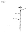
Fig. 4 is a side view showing the disc spring inFig. 3 ; -
Fig. 5 is a sectional side view showing a nozzle and its vicinity according to a further embodiment of the invention; -
Fig. 6 is a sectional side view showing a further embodiment of the vane shafts which support the nozzle vane; -
Fig. 7 is a sectional side view showing a still further embodiment of the vane shafts which support the nozzle vane; -
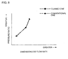
Fig. 8 is a diagram for showing conditioning conventional and claimed turbochargers to have substantially same pressure ratios between upstream and downstream sides of turbine impeller; -
Fig. 9 is a diagram showing velocity distribution of exhaust gas in radial positions in comparison of the conventional turbocharger with the claimed turbocharger; and -
Fig. 10 is a diagram showing turbine efficiency in comparison of the conventional turbocharger with the claimed turbocharger. -
- 1
- turbine housing
- 3
- bearing housing
- 4
- turbine impeller
- 5
- compressor impeller
- 8
- scroll passage
- 9
- exhaust nozzle
- 10
- front exhaust introduction wall
- 11
- rear exhaust introduction wall
- 15
- nozzle vane
- 16
- vane shaft
- 20
- turbine impeller outlet
- 23
- pressing means
- 24
- disc spring
- 27
- coiled spring
- 28
- vane shaft
- 28'
- vane shaft
- Embodiments of the invention will be described in conjunction with the attached drawings.
Fig. 3 shows an embodiment of the invention applied to the turbocharger shown inFig. 2 withnozzle vanes 15 being arranged between front and rearexhaust introduction walls exhaust nozzle 9 and each being supported in a cantilever manner by avane shaft 16 arranged on a side of thevane 15 and extending through thefront wall 10, comprising pressing means 23 arranged between a front end 16' (right end inFig. 3 ) of thevane shaft 16 of each of thenozzle vanes 15 and a rear surface 3' of a bearing housing 3 (between anozzle link plate 16a referred to hereinafter and the rear surface 3') to urge therespective vane shafts 16 toward therear wall 11 to thereby keep therespective nozzle vanes 15 always in a displaced state toward therear wall 11. - The pressing means 23 shown in
Fig. 3 is in the form of adisc spring 24 which urges therespective vane shafts 16 toward therear wall 11. As shown inFig. 4 , thedisc spring 24 is frustconical and has inner and outerperipheral edges disc spring 24 with the frustconical shape being set to be greater than a distance between the respective front ends 16' of therespective vane shafts 16 and the rear surface 3' of the bearinghousing 3. - The respective front ends 16' of the
vane shafts 16 extend through and are retained by inner ends ofnozzle link plates 16a (shaft support members) arranged between thefront wall 10 and the rear surface 3' of the bearinghousing 3. The respectivenozzle link plates 16a are pivoted about thevane shafts 16 by rotating a drive ring (not shown); the respective vane shafts 16 (nozzle vanes 15) are rotated integrally with the respectivenozzle link plates 16a through the pivotal movements of thenozzle link plates 16a. Since thedisc spring 24 is arranged in a compressed state between the front ends 16' of therespective vane shafts 16 and the rear surface 3' of the bearinghousing 3, the elastic force of thedisc spring 24 causes thevane shafts 16 to be urged toward therear wall 11, thenozzle vanes 15 being displaced toward therear wall 11. -
Fig. 5 shows a further embodiment of pressing means 23 which has a coiledspring 27 between respective front ends 16' ofvane shafts 16 and a rear surface 3' of a bearinghousing 3 so as to urge therespective vane shafts 16 toward a rearexhaust introduction wall 11. -
Fig. 6 shows a case wherevane shafts nozzle vanes 15 extend through front and rearexhaust introduction walls nozzle vanes 15 are dually supported by thevane shafts walls disc spring 24 or coiledsprings 27 shown inFig. 5 may be arranged between the front ends 16' of thevane shafts 16 and a rear surface 3' of a bearinghousing 3 so as to urge therespective vane shafts 16 toward therear wall 11. -
Fig. 7 shows a case wherevane shafts 16 and 28' are provided on opposite sides of each ofnozzle vanes 15, one 16 of the vane shafts extending through afront exhaust wall 10, the other vane shaft 28' not extending through but being embedded in a rearexhaust introduction wall 11 so that thenozzle vanes 15 are dually supported by thevane shafts 16 and 28'; also in this case, pressing means 23 comprising adisc spring 24 or coiledsprings 27 as shown inFig. 5 may be arranged between front ends 16' of thevane shafts 16 and a rear surface 3' of a bearinghousing 3 so as to urge therespective vane shafts 16 toward therear wall 11. - Mode of operation of the embodiments shown in
Figs. 3-7 is as follows. - When the pressing means 23 comprising the
disc spring 24 shown inFigs. 3 and4 or thecoiled springs 27 shown inFig. 5 is arranged between the front ends 16' of thevane shafts 16 of thenozzle vanes 15 and the rear surface 3' of the bearinghousing 3, therespective vane shafts 16 are always urged by the pressing means 23 toward therear wall 11, so that therespective nozzle vanes 15 are retained in their displaced positions toward therear wall 11. - More specifically, there exist inherently clearances between the
nozzle vanes 15 and the front and rearexhaust introduction walls nozzle vanes 15 pivotable and rotatable; and the clearances may be different between individual turbochargers. Then, as mentioned in the above, the respective vane hafts 16 are urged by the pressing means 23 toward therear wall 11, so that therespective nozzle vanes 15 are displaced toward therear wall 11 by the clearance. As a result, therespective nozzle vanes 15 contact therear wall 11 with the clearance between thenozzle vanes 15 and therear wall 11 being minimized. - In the embodiments shown in
Figs. 3 ,6 and7 , the rear surface 3' of the bearinghousing 3 has a circumference in the form offrustoconical surface 3a' (forwardly and outwardly tapered surface). Thedisc spring 24 is arranged with its outer circumference being between thefrustoconical surface 3a' and thenozzle link plates 16a and extending along thefrustoconical surface 3a'. This makes it easy to ensure a space for thedisc spring 24 without broadening the distance between the rear surface 3' and thenozzle link plates 16a. - On the conditioning that a conventional turbocharger (conventional one) and a turbocharger of the invention (claimed one) are made to have substantially same pressure ratios between upstream and downstream sides of
turbine impeller 4 as shown inFig. 8 , the inventors determined velocity distribution of exhaust gas at radial positions inturbine impeller outlet 20 through numerical analysis. The results are shown inFig. 9 . - As is clear from
Fig. 9 , in comparison with the conventional one, the claimed one has radially flattened flow velocity distribution with less deviation. This means that the claimed one has less turbulence of exhaust gas inturbine impeller outlet 20 in comparison with the conventional one. - Moreover, turbine efficiency was compared between the claimed and conventional ones through numerical analysis. As a result, it was found out as shown in
Fig. 10 that the claimed one has turbine efficiency improved by about 10% relative to the conventional one. - The exhaust gas in the
scroll passage 8 passes through thenozzle vanes 15 of theexhaust nozzle 9 into theturbine impeller 4. Because of such exhaust gas flow being a complex three-dimensional stream, it is much difficult to find out factors in turbulence of the exhaust gas in theturbine impeller outlet 20. - However, as mentioned in the above, when the clearance between the
respective nozzle vanes 15 and therear wall 11 is minimized by urging therespective vane shafts 16 toward therear wall 11, then the velocity distribution of the exhaust gas at radial positions in theturbine impeller outlet 20 becomes flattened to reduce the turbulence of the exhaust gas in theturbine impeller outlet 20, whereby the turbine efficiency can be improved. Thus, it was found out that the clearance between therespective nozzle vanes 15 and therear wall 11 is one of factors affecting turbulence of the exhaust gas in theturbine impeller outlet 20. - Thus, according to the invention, by the above-mentioned simple structure that the pressing means 23 is arranged between the bearing
housing 3 and therespective vane shafts 16 of thenozzle vanes 15, thenozzle vanes 15 are displaced toward therear wall 11 to keep in the minimized state the clearance between therespective nozzle vanes 15 and therear wall 11, whereby the turbulence of the fluid in theturbine impeller outlet 20 can be reduced to substantially improve the efficiency of the turbine. - It is to be understood that the invention is not limited to the above embodiments and that various changes and modifications may be made without departing form the scope of the invention. For example, though the sealing device in the form of the piston rings 21 for the
gap 19 has been exemplified in the above embodiments, there is no restriction or limitation on construction of the sealing device. - A turbocharger according to the invention can be applied to displace nozzle vanes toward a rear exhaust introduction wall to minimize clearance between the respective nozzle vanes and the rear wall, thereby reducing turbulence of fluid in a turbine impeller outlet to improve efficiency of a turbine.
Claims (6)
- A turbocharger with a bearing housing having a scroll passage outwardly of an exhaust nozzle which in turn is arranged outwardly of a turbine impeller rotatably supported on the bearing housing, said exhaust nozzle having a plurality of nozzle vanes between front and rear exhaust introduction walls on sides of the bearing and turbine housings, respectively, a vane shaft for each of said nozzle vanes extending at least through the front wall and being rotatably supported, characterized in that it comprises pressing means arranged between the respective vane shafts and the bearing housing for urging the respective vane shafts toward the rear wall to displace the nozzle vanes toward the rear wall.
- A turbocharger as claimed in claim 1, wherein said pressing means is a disc spring between the vane shafts and the bearing housing.
- A turbocharger as claimed in claim 1, wherein said pressing means is a coiled spring between each of the vane shafts and the bearing housing.
- A turbocharger as claimed in any one of claims 1-3, wherein each of said nozzle vanes is supported in a cantilever manner by the vane shaft on one side of the vane extending through the front wall.
- A turbocharger as claimed in any one of claims 1-3, wherein each of said nozzle vanes is dually supported by vane shafts on opposite sides of the vane extending through the front and rear walls, respectively.
- A turbocharger as claimed in any one of claims 1-3, wherein each of said nozzle vanes is dually supported by vane shafts on opposite sides of the vane, one of the vane shafts extending through the front wall, the other vane shaft being embedded in the rear wall.
Applications Claiming Priority (2)
| Application Number | Priority Date | Filing Date | Title |
|---|---|---|---|
| JP2007320719A JP2009144546A (en) | 2007-12-12 | 2007-12-12 | Turbocharger |
| PCT/JP2008/003282 WO2009075057A1 (en) | 2007-12-12 | 2008-11-12 | Turbocharger |
Publications (3)
| Publication Number | Publication Date |
|---|---|
| EP2233718A1 true EP2233718A1 (en) | 2010-09-29 |
| EP2233718A4 EP2233718A4 (en) | 2011-08-03 |
| EP2233718B1 EP2233718B1 (en) | 2014-04-09 |
Family
ID=40755307
Family Applications (1)
| Application Number | Title | Priority Date | Filing Date |
|---|---|---|---|
| EP08859176.3A Not-in-force EP2233718B1 (en) | 2007-12-12 | 2008-11-12 | Turbocharger |
Country Status (6)
| Country | Link |
|---|---|
| US (1) | US20100310363A1 (en) |
| EP (1) | EP2233718B1 (en) |
| JP (1) | JP2009144546A (en) |
| KR (1) | KR101196248B1 (en) |
| CN (1) | CN101896705A (en) |
| WO (1) | WO2009075057A1 (en) |
Cited By (4)
| Publication number | Priority date | Publication date | Assignee | Title |
|---|---|---|---|---|
| WO2017005470A1 (en) * | 2015-07-08 | 2017-01-12 | Continental Automotive Gmbh | Exhaust-gas turbocharger with adjustable turbine geometry |
| GB2616516A (en) * | 2022-02-16 | 2023-09-13 | Transp Ip Holdings Llc | Semi-floating turbine nozzle ring |
| DE102022105348A1 (en) | 2022-03-08 | 2023-09-14 | Avl Schrick Gmbh | Exhaust gas turbocharger fixation |
| US12467382B2 (en) | 2021-06-08 | 2025-11-11 | Ihi Corporation | Turbine with biased nozzle vane members |
Families Citing this family (15)
| Publication number | Priority date | Publication date | Assignee | Title |
|---|---|---|---|---|
| JP5397144B2 (en) * | 2009-10-14 | 2014-01-22 | 株式会社Ihi | Assembly method of variable nozzle unit |
| US9988939B2 (en) | 2010-09-13 | 2018-06-05 | Ihi Corporation | Fixed vane-type turbocharger |
| JP5861287B2 (en) * | 2011-07-06 | 2016-02-16 | 株式会社Ihi | Turbocharger |
| JP5710452B2 (en) * | 2011-11-16 | 2015-04-30 | トヨタ自動車株式会社 | Turbocharger |
| JP2013104412A (en) * | 2011-11-16 | 2013-05-30 | Toyota Motor Corp | Variable nozzle mechanism |
| KR101657527B1 (en) * | 2012-03-08 | 2016-09-19 | 한화테크윈 주식회사 | Fluid machine with variable nozzle |
| US9664060B2 (en) | 2013-03-01 | 2017-05-30 | Ihi Corporation | Variable nozzle unit and variable geometry system turbocharger |
| JP6152049B2 (en) * | 2013-12-19 | 2017-06-21 | 株式会社Ihi | Variable nozzle unit and variable capacity turbocharger |
| JP6542246B2 (en) | 2014-10-02 | 2019-07-10 | 株式会社Ihi | Variable displacement turbocharger |
| KR101700386B1 (en) | 2016-09-01 | 2017-01-26 | 주식회사 조일기업 | Cartridge filter connecting structure |
| DE102016125189B4 (en) * | 2016-12-21 | 2020-11-26 | Man Energy Solutions Se | turbocharger |
| EP3929407A1 (en) * | 2020-06-23 | 2021-12-29 | ABB Schweiz AG | Modular nozzle ring for a turbine stage of a flow engine |
| WO2022054763A1 (en) * | 2020-09-14 | 2022-03-17 | 株式会社Ihi | Supercharger |
| GB2612999A (en) * | 2021-11-18 | 2023-05-24 | Cummins Ltd | Turbine |
| US20250347228A1 (en) * | 2022-07-06 | 2025-11-13 | Mitsubishi Heavy Industries Engine & Turbocharger, Ltd. | Turbine and turbocharger |
Family Cites Families (12)
| Publication number | Priority date | Publication date | Assignee | Title |
|---|---|---|---|---|
| JPH0610403B2 (en) * | 1984-02-22 | 1994-02-09 | 日産自動車株式会社 | Variable nozzle of Radiator bottle |
| US4659295A (en) * | 1984-04-20 | 1987-04-21 | The Garrett Corporation | Gas seal vanes of variable nozzle turbine |
| JPS6361545U (en) * | 1986-10-09 | 1988-04-23 | ||
| JP3664761B2 (en) * | 1994-12-22 | 2005-06-29 | 三菱重工業株式会社 | Exhaust turbocharger variable capacity turbine |
| DE10048105A1 (en) * | 2000-09-28 | 2002-04-11 | Daimler Chrysler Ag | Angle turbocharger for an internal combustion engine with variable turbine geometry |
| GB0227473D0 (en) * | 2002-11-25 | 2002-12-31 | Leavesley Malcolm G | Variable turbocharger apparatus with bypass apertures |
| DE10311205B3 (en) * | 2003-03-14 | 2004-09-16 | Man B & W Diesel Ag | Guiding device for a radial turbine of a turbocharger of a lifting piston I.C. engine operating with heavy oil has blades with shafts positioned in a housing part of the device facing a compressor of the turbocharger |
| DE10325985A1 (en) * | 2003-06-07 | 2004-12-23 | Ihi Charging Systems International Gmbh | Guide device for an exhaust gas turbine |
| JP4729901B2 (en) | 2004-11-01 | 2011-07-20 | 株式会社Ihi | Turbocharger and sealing device |
| EP1811134A1 (en) * | 2006-01-23 | 2007-07-25 | ABB Turbo Systems AG | Variable guiding device |
| EP1816317B1 (en) * | 2006-02-02 | 2013-06-12 | IHI Corporation | Turbocharger with variable nozzle |
| JP4745847B2 (en) * | 2006-02-03 | 2011-08-10 | 株式会社アキタファインブランキング | Turbine frame that rotatably holds variable blades in an exhaust guide assembly of a VGS type turbocharger |
-
2007
- 2007-12-12 JP JP2007320719A patent/JP2009144546A/en active Pending
-
2008
- 2008-11-12 WO PCT/JP2008/003282 patent/WO2009075057A1/en not_active Ceased
- 2008-11-12 CN CN2008801210387A patent/CN101896705A/en active Pending
- 2008-11-12 EP EP08859176.3A patent/EP2233718B1/en not_active Not-in-force
- 2008-11-12 US US12/745,351 patent/US20100310363A1/en not_active Abandoned
- 2008-11-12 KR KR1020107012893A patent/KR101196248B1/en not_active Expired - Fee Related
Cited By (6)
| Publication number | Priority date | Publication date | Assignee | Title |
|---|---|---|---|---|
| WO2017005470A1 (en) * | 2015-07-08 | 2017-01-12 | Continental Automotive Gmbh | Exhaust-gas turbocharger with adjustable turbine geometry |
| US10774732B2 (en) | 2015-07-08 | 2020-09-15 | Vitesco Technologies GmbH | Exhaust-gas turbocharger with adjustable turbine geometry |
| US12467382B2 (en) | 2021-06-08 | 2025-11-11 | Ihi Corporation | Turbine with biased nozzle vane members |
| DE112022001022B4 (en) * | 2021-06-08 | 2026-01-15 | Ihi Corporation | Turbine and turbocharger |
| GB2616516A (en) * | 2022-02-16 | 2023-09-13 | Transp Ip Holdings Llc | Semi-floating turbine nozzle ring |
| DE102022105348A1 (en) | 2022-03-08 | 2023-09-14 | Avl Schrick Gmbh | Exhaust gas turbocharger fixation |
Also Published As
| Publication number | Publication date |
|---|---|
| EP2233718B1 (en) | 2014-04-09 |
| KR20100087376A (en) | 2010-08-04 |
| JP2009144546A (en) | 2009-07-02 |
| KR101196248B1 (en) | 2012-11-05 |
| CN101896705A (en) | 2010-11-24 |
| WO2009075057A1 (en) | 2009-06-18 |
| US20100310363A1 (en) | 2010-12-09 |
| EP2233718A4 (en) | 2011-08-03 |
Similar Documents
| Publication | Publication Date | Title |
|---|---|---|
| EP2233718B1 (en) | Turbocharger | |
| EP2226484B1 (en) | Turbocharger | |
| EP2180160B1 (en) | Turbo charger | |
| JP6542246B2 (en) | Variable displacement turbocharger | |
| EP2243939A1 (en) | Turbo charger | |
| EP2530276B1 (en) | Sealing device for turbocharger | |
| CN102639838B (en) | Turbocharger | |
| CN102762838B (en) | Variable geometry turbocharger | |
| EP3026225A1 (en) | Variable geometry exhaust turbocharger and method of manufacturing | |
| WO2013072732A1 (en) | Turbocharger | |
| EP3489483B1 (en) | Variable nozzle device and variable capacity-type exhaust turbocharger | |
| KR20160147014A (en) | Variable geometry turbine assembly | |
| EP2818668B1 (en) | Turbine exhaust seal | |
| WO2010018914A1 (en) | Turbocharger equipped with a variable nozzle device | |
| EP3542031B1 (en) | Vane arrangement for a turbo-machine | |
| EP3085919A1 (en) | Variable nozzle unit and variable geometry turbocharger | |
| US12037916B2 (en) | Turbine housing | |
| JPWO2019077962A1 (en) | Supercharger seal structure | |
| JP6089791B2 (en) | Variable nozzle unit and variable capacity turbocharger | |
| JP2014169643A (en) | Variable displacement supercharger | |
| CN121013940A (en) | Rotating device | |
| CN120677313A (en) | Rotary device | |
| WO2025100059A1 (en) | Supercharger | |
| KR20050098827A (en) | Turbocharger comprising a variable nozzle device |
Legal Events
| Date | Code | Title | Description |
|---|---|---|---|
| PUAI | Public reference made under article 153(3) epc to a published international application that has entered the european phase |
Free format text: ORIGINAL CODE: 0009012 |
|
| 17P | Request for examination filed |
Effective date: 20100707 |
|
| AK | Designated contracting states |
Kind code of ref document: A1 Designated state(s): AT BE BG CH CY CZ DE DK EE ES FI FR GB GR HR HU IE IS IT LI LT LU LV MC MT NL NO PL PT RO SE SI SK TR |
|
| AX | Request for extension of the european patent |
Extension state: AL BA MK RS |
|
| DAX | Request for extension of the european patent (deleted) | ||
| A4 | Supplementary search report drawn up and despatched |
Effective date: 20110706 |
|
| RIC1 | Information provided on ipc code assigned before grant |
Ipc: F01D 17/16 20060101ALI20110630BHEP Ipc: F02B 37/24 20060101AFI20110630BHEP Ipc: F02B 39/00 20060101ALI20110630BHEP |
|
| 17Q | First examination report despatched |
Effective date: 20120424 |
|
| GRAP | Despatch of communication of intention to grant a patent |
Free format text: ORIGINAL CODE: EPIDOSNIGR1 |
|
| INTG | Intention to grant announced |
Effective date: 20131017 |
|
| GRAS | Grant fee paid |
Free format text: ORIGINAL CODE: EPIDOSNIGR3 |
|
| GRAA | (expected) grant |
Free format text: ORIGINAL CODE: 0009210 |
|
| AK | Designated contracting states |
Kind code of ref document: B1 Designated state(s): AT BE BG CH CY CZ DE DK EE ES FI FR GB GR HR HU IE IS IT LI LT LU LV MC MT NL NO PL PT RO SE SI SK TR |
|
| REG | Reference to a national code |
Ref country code: GB Ref legal event code: FG4D |
|
| REG | Reference to a national code |
Ref country code: CH Ref legal event code: EP Ref country code: AT Ref legal event code: REF Ref document number: 661477 Country of ref document: AT Kind code of ref document: T Effective date: 20140415 |
|
| REG | Reference to a national code |
Ref country code: IE Ref legal event code: FG4D |
|
| REG | Reference to a national code |
Ref country code: DE Ref legal event code: R096 Ref document number: 602008031456 Country of ref document: DE Effective date: 20140522 |
|
| REG | Reference to a national code |
Ref country code: AT Ref legal event code: MK05 Ref document number: 661477 Country of ref document: AT Kind code of ref document: T Effective date: 20140409 |
|
| REG | Reference to a national code |
Ref country code: NL Ref legal event code: VDEP Effective date: 20140409 |
|
| REG | Reference to a national code |
Ref country code: LT Ref legal event code: MG4D |
|
| PG25 | Lapsed in a contracting state [announced via postgrant information from national office to epo] |
Ref country code: GR Free format text: LAPSE BECAUSE OF FAILURE TO SUBMIT A TRANSLATION OF THE DESCRIPTION OR TO PAY THE FEE WITHIN THE PRESCRIBED TIME-LIMIT Effective date: 20140710 Ref country code: NO Free format text: LAPSE BECAUSE OF FAILURE TO SUBMIT A TRANSLATION OF THE DESCRIPTION OR TO PAY THE FEE WITHIN THE PRESCRIBED TIME-LIMIT Effective date: 20140709 Ref country code: FI Free format text: LAPSE BECAUSE OF FAILURE TO SUBMIT A TRANSLATION OF THE DESCRIPTION OR TO PAY THE FEE WITHIN THE PRESCRIBED TIME-LIMIT Effective date: 20140409 Ref country code: LT Free format text: LAPSE BECAUSE OF FAILURE TO SUBMIT A TRANSLATION OF THE DESCRIPTION OR TO PAY THE FEE WITHIN THE PRESCRIBED TIME-LIMIT Effective date: 20140409 Ref country code: BG Free format text: LAPSE BECAUSE OF FAILURE TO SUBMIT A TRANSLATION OF THE DESCRIPTION OR TO PAY THE FEE WITHIN THE PRESCRIBED TIME-LIMIT Effective date: 20140709 Ref country code: IS Free format text: LAPSE BECAUSE OF FAILURE TO SUBMIT A TRANSLATION OF THE DESCRIPTION OR TO PAY THE FEE WITHIN THE PRESCRIBED TIME-LIMIT Effective date: 20140809 Ref country code: NL Free format text: LAPSE BECAUSE OF FAILURE TO SUBMIT A TRANSLATION OF THE DESCRIPTION OR TO PAY THE FEE WITHIN THE PRESCRIBED TIME-LIMIT Effective date: 20140409 |
|
| PG25 | Lapsed in a contracting state [announced via postgrant information from national office to epo] |
Ref country code: ES Free format text: LAPSE BECAUSE OF FAILURE TO SUBMIT A TRANSLATION OF THE DESCRIPTION OR TO PAY THE FEE WITHIN THE PRESCRIBED TIME-LIMIT Effective date: 20140409 Ref country code: AT Free format text: LAPSE BECAUSE OF FAILURE TO SUBMIT A TRANSLATION OF THE DESCRIPTION OR TO PAY THE FEE WITHIN THE PRESCRIBED TIME-LIMIT Effective date: 20140409 Ref country code: PL Free format text: LAPSE BECAUSE OF FAILURE TO SUBMIT A TRANSLATION OF THE DESCRIPTION OR TO PAY THE FEE WITHIN THE PRESCRIBED TIME-LIMIT Effective date: 20140409 Ref country code: LV Free format text: LAPSE BECAUSE OF FAILURE TO SUBMIT A TRANSLATION OF THE DESCRIPTION OR TO PAY THE FEE WITHIN THE PRESCRIBED TIME-LIMIT Effective date: 20140409 Ref country code: SE Free format text: LAPSE BECAUSE OF FAILURE TO SUBMIT A TRANSLATION OF THE DESCRIPTION OR TO PAY THE FEE WITHIN THE PRESCRIBED TIME-LIMIT Effective date: 20140409 Ref country code: HR Free format text: LAPSE BECAUSE OF FAILURE TO SUBMIT A TRANSLATION OF THE DESCRIPTION OR TO PAY THE FEE WITHIN THE PRESCRIBED TIME-LIMIT Effective date: 20140409 |
|
| PG25 | Lapsed in a contracting state [announced via postgrant information from national office to epo] |
Ref country code: PT Free format text: LAPSE BECAUSE OF FAILURE TO SUBMIT A TRANSLATION OF THE DESCRIPTION OR TO PAY THE FEE WITHIN THE PRESCRIBED TIME-LIMIT Effective date: 20140811 |
|
| REG | Reference to a national code |
Ref country code: DE Ref legal event code: R097 Ref document number: 602008031456 Country of ref document: DE |
|
| PG25 | Lapsed in a contracting state [announced via postgrant information from national office to epo] |
Ref country code: BE Free format text: LAPSE BECAUSE OF FAILURE TO SUBMIT A TRANSLATION OF THE DESCRIPTION OR TO PAY THE FEE WITHIN THE PRESCRIBED TIME-LIMIT Effective date: 20140409 Ref country code: RO Free format text: LAPSE BECAUSE OF FAILURE TO SUBMIT A TRANSLATION OF THE DESCRIPTION OR TO PAY THE FEE WITHIN THE PRESCRIBED TIME-LIMIT Effective date: 20140409 Ref country code: CZ Free format text: LAPSE BECAUSE OF FAILURE TO SUBMIT A TRANSLATION OF THE DESCRIPTION OR TO PAY THE FEE WITHIN THE PRESCRIBED TIME-LIMIT Effective date: 20140409 Ref country code: DK Free format text: LAPSE BECAUSE OF FAILURE TO SUBMIT A TRANSLATION OF THE DESCRIPTION OR TO PAY THE FEE WITHIN THE PRESCRIBED TIME-LIMIT Effective date: 20140409 Ref country code: EE Free format text: LAPSE BECAUSE OF FAILURE TO SUBMIT A TRANSLATION OF THE DESCRIPTION OR TO PAY THE FEE WITHIN THE PRESCRIBED TIME-LIMIT Effective date: 20140409 Ref country code: SK Free format text: LAPSE BECAUSE OF FAILURE TO SUBMIT A TRANSLATION OF THE DESCRIPTION OR TO PAY THE FEE WITHIN THE PRESCRIBED TIME-LIMIT Effective date: 20140409 |
|
| PLBE | No opposition filed within time limit |
Free format text: ORIGINAL CODE: 0009261 |
|
| STAA | Information on the status of an ep patent application or granted ep patent |
Free format text: STATUS: NO OPPOSITION FILED WITHIN TIME LIMIT |
|
| 26N | No opposition filed |
Effective date: 20150112 |
|
| REG | Reference to a national code |
Ref country code: DE Ref legal event code: R097 Ref document number: 602008031456 Country of ref document: DE Effective date: 20150112 |
|
| PG25 | Lapsed in a contracting state [announced via postgrant information from national office to epo] |
Ref country code: MC Free format text: LAPSE BECAUSE OF FAILURE TO SUBMIT A TRANSLATION OF THE DESCRIPTION OR TO PAY THE FEE WITHIN THE PRESCRIBED TIME-LIMIT Effective date: 20140409 Ref country code: LU Free format text: LAPSE BECAUSE OF FAILURE TO SUBMIT A TRANSLATION OF THE DESCRIPTION OR TO PAY THE FEE WITHIN THE PRESCRIBED TIME-LIMIT Effective date: 20141112 |
|
| REG | Reference to a national code |
Ref country code: CH Ref legal event code: PL |
|
| GBPC | Gb: european patent ceased through non-payment of renewal fee |
Effective date: 20141112 |
|
| PG25 | Lapsed in a contracting state [announced via postgrant information from national office to epo] |
Ref country code: SI Free format text: LAPSE BECAUSE OF FAILURE TO SUBMIT A TRANSLATION OF THE DESCRIPTION OR TO PAY THE FEE WITHIN THE PRESCRIBED TIME-LIMIT Effective date: 20140409 Ref country code: LI Free format text: LAPSE BECAUSE OF NON-PAYMENT OF DUE FEES Effective date: 20141130 Ref country code: CH Free format text: LAPSE BECAUSE OF NON-PAYMENT OF DUE FEES Effective date: 20141130 |
|
| REG | Reference to a national code |
Ref country code: IE Ref legal event code: MM4A |
|
| REG | Reference to a national code |
Ref country code: FR Ref legal event code: PLFP Year of fee payment: 8 |
|
| PG25 | Lapsed in a contracting state [announced via postgrant information from national office to epo] |
Ref country code: IE Free format text: LAPSE BECAUSE OF NON-PAYMENT OF DUE FEES Effective date: 20141112 Ref country code: GB Free format text: LAPSE BECAUSE OF NON-PAYMENT OF DUE FEES Effective date: 20141112 |
|
| PG25 | Lapsed in a contracting state [announced via postgrant information from national office to epo] |
Ref country code: CY Free format text: LAPSE BECAUSE OF FAILURE TO SUBMIT A TRANSLATION OF THE DESCRIPTION OR TO PAY THE FEE WITHIN THE PRESCRIBED TIME-LIMIT Effective date: 20140409 |
|
| PG25 | Lapsed in a contracting state [announced via postgrant information from national office to epo] |
Ref country code: TR Free format text: LAPSE BECAUSE OF FAILURE TO SUBMIT A TRANSLATION OF THE DESCRIPTION OR TO PAY THE FEE WITHIN THE PRESCRIBED TIME-LIMIT Effective date: 20140409 Ref country code: HU Free format text: LAPSE BECAUSE OF FAILURE TO SUBMIT A TRANSLATION OF THE DESCRIPTION OR TO PAY THE FEE WITHIN THE PRESCRIBED TIME-LIMIT; INVALID AB INITIO Effective date: 20081112 Ref country code: MT Free format text: LAPSE BECAUSE OF FAILURE TO SUBMIT A TRANSLATION OF THE DESCRIPTION OR TO PAY THE FEE WITHIN THE PRESCRIBED TIME-LIMIT Effective date: 20140409 |
|
| REG | Reference to a national code |
Ref country code: FR Ref legal event code: PLFP Year of fee payment: 9 |
|
| REG | Reference to a national code |
Ref country code: FR Ref legal event code: PLFP Year of fee payment: 10 |
|
| PGFP | Annual fee paid to national office [announced via postgrant information from national office to epo] |
Ref country code: FR Payment date: 20171012 Year of fee payment: 10 |
|
| PGFP | Annual fee paid to national office [announced via postgrant information from national office to epo] |
Ref country code: DE Payment date: 20181030 Year of fee payment: 11 |
|
| PGFP | Annual fee paid to national office [announced via postgrant information from national office to epo] |
Ref country code: IT Payment date: 20181122 Year of fee payment: 11 |
|
| PG25 | Lapsed in a contracting state [announced via postgrant information from national office to epo] |
Ref country code: FR Free format text: LAPSE BECAUSE OF NON-PAYMENT OF DUE FEES Effective date: 20181130 |
|
| REG | Reference to a national code |
Ref country code: DE Ref legal event code: R119 Ref document number: 602008031456 Country of ref document: DE |
|
| PG25 | Lapsed in a contracting state [announced via postgrant information from national office to epo] |
Ref country code: IT Free format text: LAPSE BECAUSE OF NON-PAYMENT OF DUE FEES Effective date: 20191112 Ref country code: DE Free format text: LAPSE BECAUSE OF NON-PAYMENT OF DUE FEES Effective date: 20200603 |