EP2233700A1 - Self balancing face seals and gas turbine engine systems involving such seals - Google Patents
Self balancing face seals and gas turbine engine systems involving such seals Download PDFInfo
- Publication number
- EP2233700A1 EP2233700A1 EP09250656A EP09250656A EP2233700A1 EP 2233700 A1 EP2233700 A1 EP 2233700A1 EP 09250656 A EP09250656 A EP 09250656A EP 09250656 A EP09250656 A EP 09250656A EP 2233700 A1 EP2233700 A1 EP 2233700A1
- Authority
- EP
- European Patent Office
- Prior art keywords
- seal
- face
- assembly
- runner
- operative
- Prior art date
- Legal status (The legal status is an assumption and is not a legal conclusion. Google has not performed a legal analysis and makes no representation as to the accuracy of the status listed.)
- Granted
Links
- 230000002706 hydrostatic effect Effects 0.000 claims abstract description 27
- OKTJSMMVPCPJKN-UHFFFAOYSA-N Carbon Chemical compound [C] OKTJSMMVPCPJKN-UHFFFAOYSA-N 0.000 claims description 5
- 229910052799 carbon Inorganic materials 0.000 claims description 5
- 230000003993 interaction Effects 0.000 description 7
- 238000010586 diagram Methods 0.000 description 6
- 238000006073 displacement reaction Methods 0.000 description 6
- 238000007789 sealing Methods 0.000 description 3
- 230000006866 deterioration Effects 0.000 description 2
- 230000012010 growth Effects 0.000 description 2
- 238000000034 method Methods 0.000 description 2
- 238000000926 separation method Methods 0.000 description 2
- 238000002485 combustion reaction Methods 0.000 description 1
- 230000009977 dual effect Effects 0.000 description 1
- 238000012986 modification Methods 0.000 description 1
- 230000004048 modification Effects 0.000 description 1
- 230000003071 parasitic effect Effects 0.000 description 1
- 230000003068 static effect Effects 0.000 description 1
- 238000009966 trimming Methods 0.000 description 1
Images


Classifications
-
- F—MECHANICAL ENGINEERING; LIGHTING; HEATING; WEAPONS; BLASTING
- F01—MACHINES OR ENGINES IN GENERAL; ENGINE PLANTS IN GENERAL; STEAM ENGINES
- F01D—NON-POSITIVE DISPLACEMENT MACHINES OR ENGINES, e.g. STEAM TURBINES
- F01D11/00—Preventing or minimising internal leakage of working-fluid, e.g. between stages
- F01D11/02—Preventing or minimising internal leakage of working-fluid, e.g. between stages by non-contact sealings, e.g. of labyrinth type
- F01D11/025—Seal clearance control; Floating assembly; Adaptation means to differential thermal dilatations
-
- F—MECHANICAL ENGINEERING; LIGHTING; HEATING; WEAPONS; BLASTING
- F01—MACHINES OR ENGINES IN GENERAL; ENGINE PLANTS IN GENERAL; STEAM ENGINES
- F01D—NON-POSITIVE DISPLACEMENT MACHINES OR ENGINES, e.g. STEAM TURBINES
- F01D11/00—Preventing or minimising internal leakage of working-fluid, e.g. between stages
- F01D11/001—Preventing or minimising internal leakage of working-fluid, e.g. between stages for sealing space between stator blade and rotor
-
- F—MECHANICAL ENGINEERING; LIGHTING; HEATING; WEAPONS; BLASTING
- F01—MACHINES OR ENGINES IN GENERAL; ENGINE PLANTS IN GENERAL; STEAM ENGINES
- F01D—NON-POSITIVE DISPLACEMENT MACHINES OR ENGINES, e.g. STEAM TURBINES
- F01D11/00—Preventing or minimising internal leakage of working-fluid, e.g. between stages
- F01D11/003—Preventing or minimising internal leakage of working-fluid, e.g. between stages by packing rings; Mechanical seals
-
- F—MECHANICAL ENGINEERING; LIGHTING; HEATING; WEAPONS; BLASTING
- F02—COMBUSTION ENGINES; HOT-GAS OR COMBUSTION-PRODUCT ENGINE PLANTS
- F02C—GAS-TURBINE PLANTS; AIR INTAKES FOR JET-PROPULSION PLANTS; CONTROLLING FUEL SUPPLY IN AIR-BREATHING JET-PROPULSION PLANTS
- F02C7/00—Features, components parts, details or accessories, not provided for in, or of interest apart form groups F02C1/00 - F02C6/00; Air intakes for jet-propulsion plants
- F02C7/28—Arrangement of seals
-
- F—MECHANICAL ENGINEERING; LIGHTING; HEATING; WEAPONS; BLASTING
- F16—ENGINEERING ELEMENTS AND UNITS; GENERAL MEASURES FOR PRODUCING AND MAINTAINING EFFECTIVE FUNCTIONING OF MACHINES OR INSTALLATIONS; THERMAL INSULATION IN GENERAL
- F16J—PISTONS; CYLINDERS; SEALINGS
- F16J15/00—Sealings
- F16J15/16—Sealings between relatively-moving surfaces
- F16J15/34—Sealings between relatively-moving surfaces with slip-ring pressed against a more or less radial face on one member
- F16J15/3404—Sealings between relatively-moving surfaces with slip-ring pressed against a more or less radial face on one member and characterised by parts or details relating to lubrication, cooling or venting of the seal
- F16J15/3408—Sealings between relatively-moving surfaces with slip-ring pressed against a more or less radial face on one member and characterised by parts or details relating to lubrication, cooling or venting of the seal at least one ring having an uneven slipping surface
- F16J15/3412—Sealings between relatively-moving surfaces with slip-ring pressed against a more or less radial face on one member and characterised by parts or details relating to lubrication, cooling or venting of the seal at least one ring having an uneven slipping surface with cavities
- F16J15/342—Sealings between relatively-moving surfaces with slip-ring pressed against a more or less radial face on one member and characterised by parts or details relating to lubrication, cooling or venting of the seal at least one ring having an uneven slipping surface with cavities with means for feeding fluid directly to the face
-
- F—MECHANICAL ENGINEERING; LIGHTING; HEATING; WEAPONS; BLASTING
- F16—ENGINEERING ELEMENTS AND UNITS; GENERAL MEASURES FOR PRODUCING AND MAINTAINING EFFECTIVE FUNCTIONING OF MACHINES OR INSTALLATIONS; THERMAL INSULATION IN GENERAL
- F16J—PISTONS; CYLINDERS; SEALINGS
- F16J15/00—Sealings
- F16J15/16—Sealings between relatively-moving surfaces
- F16J15/34—Sealings between relatively-moving surfaces with slip-ring pressed against a more or less radial face on one member
- F16J15/3464—Mounting of the seal
- F16J15/3472—Means for centering or aligning the contacting faces
Definitions
- the disclosure generally relates to gas turbine engines.
- a gas turbine engine typically maintains pressure differentials between various components during operation. These pressure differentials are commonly maintained by various configurations of seals.
- labyrinth seals oftentimes are used in gas turbine engines.
- labyrinth seals tend to deteriorate over time.
- a labyrinth seal can deteriorate due to rub interactions from thermal and mechanical growths, assembly tolerances, engine loads and maneuver deflections.
- rub interactions from thermal and mechanical growths, assembly tolerances, engine loads and maneuver deflections.
- such deterioration can cause increased flow consumption resulting in increased parasitic losses and thermodynamic cycle loss.
- an exemplary embodiment of a self-balancing face seal assembly comprises: a rotatable seal runner having a first seal runner face and an opposing second seal runner face; a first face seal operative to form a first seal with the first seal runner face, the first face seal being one of a hydrostatic seal and a hydrodynamic seal; and a second face seal operative to form a second seal with the second seal runner face, the second face seal being one of a hydrostatic seal and a hydrodynamic seal.
- An exemplary embodiment of a turbine assembly for a gas turbine engine comprises: a turbine having rotatable blades and a self-balancing face seal assembly; the self-balancing face seal assembly having a seal runner, a first face seal and a second face seal; the seal runner having a first seal runner face and a second seal runner face; the first face seal being operative to form a first seal with the first seal runner face, the first face seal being one of a hydrostatic seal and a hydrodynamic seal; and the second face seal being operative to form a second seal with the second seal runner face, the second face seal being one of a hydrostatic seal and a hydrodynamic seal.
- An exemplary embodiment of a gas turbine engine comprises: a compressor; a shaft interconnected with the compressor; and a turbine operative to drive the shaft, the turbine having a self-balancing face seal assembly having a seal runner, a first face seal and a second face seal; the seal runner having a first seal runner face and a second seal runner face; the first face seal being operative to form a first seal with the first seal runner face, the first face seal being one of a hydrostatic seal and a hydrodynamic seal; and the second face seal being operative to form a second seal with the second seal runner face, the second face seal being one of a hydrostatic seal and a hydrodynamic seal.
- self-balancing face seals use hydrostatic and/or hydrodynamic forces to position adjustable seal faces adjacent to the opposing sides of a seal runner.
- a self-balancing face seal can be used at various locations of a gas turbine engine, for example, such as in association with a low-pressure turbine.
- FIG. 1 An exemplary embodiment of a self-balancing face seal assembly is depicted schematically in FIG. 1 .
- face seal assembly 10 incorporates opposing face seals 12 and 14 that are formed by portions of a stationary stator assembly 16 and a portion of a rotating rotor assembly 18.
- rotor assembly 18 provides a seal runner 20.
- Stator assembly 16 includes an arm 22 that facilitates attachment, removal and/or placement of the face seals.
- a carrier 24 of the stator assembly includes a carrier member 26 (which carries face seal 12) and a carrier member 28 (which carries face seal 14).
- Carrier 24 accommodates differential thermal growth of the rotor assembly and the stator assembly.
- each of the face seals is annular in shape.
- Each of the face seals 12, 14 includes a seal face (i.e., a seal-forming surface).
- face seal 12 includes a seal face 32 and face seal 14 includes a seal face 34.
- Carrier member 26 is axially translatable so that seal face 32 can move, with carrier member 26, away from or toward face 42 of seal runner 20.
- carrier member 28 is axially translatable so that seal face 34 can move, with carrier member 28, away from or toward face 44 of seal runner 20.
- an anti-rotation feature 46 is provided to prevent circumferential displacement of carrier member 26 with respect to the arm 22 and to assist in aligning the carrier member 26 to facilitate axial translation.
- An anti-rotation feature 48 is provided to prevent circumferential displacement of carrier member 28 with respect to carrier member 26.
- a biasing member 50 biases the carrier members 26, 28 together to establish a defined clearance between the seal faces 32, 34.
- the defined clearance can be selected to maintain a desired pressure differential between a high-pressure side (P HIGH ) and a low-pressure side (P LOW ) of the seal assembly.
- multiple biasing members may be spaced about the carrier.
- a secondary seal 52 e.g., a piston ring is captured between opposing surfaces 54, 56 of the arm 22 and carrier member 26, respectively, to control gas leakage between the arm and the carrier.
- face seals 12 and 14 can be hydrostatic seals or hydrodynamic seals.
- a hydrostatic seal is a seal that uses balanced static pressure forces as opening and closing forces to maintain a desired separation between a seal face and a corresponding seal runner.
- a hydrodynamic seal is a seal that uses balanced dynamic pressure forces as opening and closing forces to maintain a desired separation between a seal face and a corresponding seal runner.
- one or both of the seal face and corresponding seal runner can include surface features for generating the dynamic pressure forces when the seal runner rotates relative to the seal face.
- both face seals of a particular seal assembly are of the same type.
- seal faces 32, 34 and the seal runner faces 42, 44 should not contact each other.
- a material containing carbon can be used as a seal face material. It should be noted, however, that carbon can fracture or otherwise be damaged due to unintended contact (e.g., excessively forceful contact) between the seal face and the seal runner as may be caused by severe pressure fluctuations and/or vibrations, for example. It should also be noted that carbon may be susceptible to deterioration at higher temperatures. Therefore, carbon should be used in locations where predicted temperatures are not excessive such as in the low-pressure turbine. By way of example, use of such a material may not be appropriate, in some embodiments, in a high-pressure turbine.
- FIG. 2 is a schematic diagram depicting an exemplary embodiment of a gas turbine engine that incorporates at least one self-balancing face seal.
- engine 100 is configured as a turbofan gas turbine engine that incorporates a fan 102, a compressor section 104, a combustion section 106 and a turbine section 108.
- FIG. 2 is configured as a turbofan, there is no intention to limit the concepts described herein to use with turbofans. That is, self-balancing face seals can be used in various other configurations of gas turbine engines, as well as in other systems in which maintaining a pressure differential between rotating and nonrotating components is desired.
- engine 100 is a dual spool engine that includes a high-pressure turbine 110 interconnected with a high-pressure compressor 112 via a shaft 114, and a low-pressure turbine 120 interconnected with a low-pressure compressor 122 via a shaft 124.
- low-pressure turbine 120 defines a primary gas flow path 130 along which multiple rotating blades (e.g., blade 132) and stationary vanes (e.g., vane 134) are located.
- the blades are mounted to turbine disks, the respective webs and bores of which extend into a high-pressure cavity 140.
- disk 142 includes a web 144 and a bore 146, each of which extends into cavity 140.
- a relatively lower-pressure cavity 148 is oriented between high-pressure cavity 140 and turbine hub 150, with a self-balancing face seal assembly 10 (described in detail before with respect to FIG. 1 ) being provided to maintain a pressure differential between the high-pressure cavity and the lower-pressure cavity.
- a self-balancing face seal assembly 10 (described in detail before with respect to FIG. 1 ) being provided to maintain a pressure differential between the high-pressure cavity and the lower-pressure cavity.
- the rotor assembly 18 (which includes the seal runner 20) is provided by a removable bracket that is mounted to the low-pressure turbine hub 150.
- the stator assembly 16 (which provides arm 22 and carrier 24) is provided by a removable bracket that is mounted to a stationary portion of the engine.
- face seal assembly 210 incorporates opposing hydrostatic face seals 212 and 214 that are formed by portions of a stationary stator assembly 216 and a portion of a rotating rotor assembly 218.
- rotor assembly 218 provides a seal runner 220.
- Stator assembly 216 includes an arm 222 that facilitates attachment, removal and/or placement of the face seals.
- a carrier 224 of the stator assembly includes a carrier member 226 (which carries face seal 212) and a carrier member 228 (which carries face seal 214).
- Hydrostatic face seal 214 includes a seal face 234, a seal dam 239, and an air bearing 243 that is fed via air passage 241 with air from the high-pressure side (P HIGH ) of the seal assembly 210.
- Air bearing air and leakage air passing air dam 239 will be discharged into a plenum 280 formed between hydrostatic face seal 214, hydrostatic face seal 212, rotor assembly 218, and carrier 224.
- Air pressure in plenum 280 will be at an intermediate pressure (P INT ) that is smaller than the high pressure side (P HIGH ) but larger than the low pressure side (P LOW ) of assembly 210.
- Hydrostatic face seal 212 includes a seal face 232, which incorporates a seal dam 233, and air bearing 237 that is fed via air passage 235 with air from the intermediate-pressure plenum 280. Air bearing air and leakage air passing air dam 233 will be discharged to the low pressure side (P LOW ) of assembly 210.
- Carrier member 226 is axially translatable so that seal face 232 can move, with carrier member 226, away from or toward face 242 of seal runner 220.
- carrier member 228 is axially translatable so that seal face 234 can move, with carrier member 228, away from or toward face 244 of seal runner 220.
- An anti-rotation feature 246 is provided to prevent circumferential displacement of carrier member 226 with respect to the arm 222 and to assist in aligning the carrier member 226 to facilitate axial translation.
- An anti-rotation feature 248 is provided to prevent circumferential displacement of carrier member 228 with respect to carrier member 226.
- a biasing member 250 biases the carrier members 226, 228 together to establish a defined clearance between the seal faces 232, 234. Additionally, a piston ring 252 is captured between opposing surfaces 254, 256 of the arm 222 and carrier member 226, respectively, to control gas leakage between the arm and the carrier.
- face seal assembly 310 incorporates opposing hydrodynamic face seals 312 and 314 that are formed by portions of a stationary stator assembly 316 and a portion of a rotating rotor assembly 318.
- rotor assembly 318 provides a seal runner 320.
- Stator assembly 316 includes an arm 322 that facilitates attachment, removal and/or placement of the face seals.
- a carrier 324 of the stator assembly includes a carrier member 326 (which carries face seal 312) and a carrier member 328 (which carries face seal 314).
- Hydrodynamic face seal 312 includes a seal face 332, and hydrodynamic face seal 314 includes a seal face 334.
- Carrier member 226 is axially translatable so that seal face 332 can move, with carrier member 326, away from or toward face 342 of seal runner 320.
- carrier member 328 is axially translatable so that seal face 334 can move, with carrier member 328, away from or toward face 344 of seal runner 320.
- seal face 332 and seal runner face 342 can include surface features for generating hydrodynamic forces when the seal runner rotates relative to the seal face.
- one or both of seal face 334 and seal runner face 344 can include surface features for generating hydrodynamic forces.
- An anti-rotation feature 346 is provided to prevent circumferential displacement of carrier member 326 with respect to the arm 322 and to assist in aligning the carrier member 326 to facilitate axial translation.
- An anti-rotation feature 348 is provided to prevent circumferential displacement of carrier member 328 with respect to carrier member 326.
- a biasing member 350 biases the carrier members 326, 328 to establish a defined clearance between the seal faces 332, 334. Additionally, a secondary seal 352 is positioned between opposing surfaces 354, 356 of the arm 322 and carrier member 326, respectively, to control gas leakage between the arm and the carrier.
Abstract
Description
- The disclosure generally relates to gas turbine engines.
- A gas turbine engine typically maintains pressure differentials between various components during operation. These pressure differentials are commonly maintained by various configurations of seals. In this regard, labyrinth seals oftentimes are used in gas turbine engines. As is known, labyrinth seals tend to deteriorate over time. By way of example, a labyrinth seal can deteriorate due to rub interactions from thermal and mechanical growths, assembly tolerances, engine loads and maneuver deflections. Unfortunately, such deterioration can cause increased flow consumption resulting in increased parasitic losses and thermodynamic cycle loss.
- Self-balancing face seals and gas turbine engine systems involving such seals are provided. In this regard, an exemplary embodiment of a self-balancing face seal assembly comprises: a rotatable seal runner having a first seal runner face and an opposing second seal runner face; a first face seal operative to form a first seal with the first seal runner face, the first face seal being one of a hydrostatic seal and a hydrodynamic seal; and a second face seal operative to form a second seal with the second seal runner face, the second face seal being one of a hydrostatic seal and a hydrodynamic seal.
- An exemplary embodiment of a turbine assembly for a gas turbine engine comprises: a turbine having rotatable blades and a self-balancing face seal assembly; the self-balancing face seal assembly having a seal runner, a first face seal and a second face seal; the seal runner having a first seal runner face and a second seal runner face; the first face seal being operative to form a first seal with the first seal runner face, the first face seal being one of a hydrostatic seal and a hydrodynamic seal; and the second face seal being operative to form a second seal with the second seal runner face, the second face seal being one of a hydrostatic seal and a hydrodynamic seal.
- An exemplary embodiment of a gas turbine engine comprises: a compressor; a shaft interconnected with the compressor; and a turbine operative to drive the shaft, the turbine having a self-balancing face seal assembly having a seal runner, a first face seal and a second face seal; the seal runner having a first seal runner face and a second seal runner face; the first face seal being operative to form a first seal with the first seal runner face, the first face seal being one of a hydrostatic seal and a hydrodynamic seal; and the second face seal being operative to form a second seal with the second seal runner face, the second face seal being one of a hydrostatic seal and a hydrodynamic seal.
- Other systems, methods, features and/or advantages of this disclosure will be or may become apparent to one with skill in the art upon examination of the following drawings and detailed description. It is intended that all such additional systems, methods, features and/or advantages be included within this description and be within the scope of the present disclosure.
- Many aspects of the disclosure can be better understood with reference to the following drawings. The components in the drawings are not necessarily to scale. Moreover, in the drawings, like reference numerals designate corresponding parts throughout the several views.
-
FIG. 1 is a schematic diagram depicting an exemplary embodiment of a self-balancing face seal. -
FIG. 2 is a schematic diagram depicting an exemplary embodiment of a gas turbine engine. -
FIG. 3 is a schematic diagram depicting a portion of the low-pressure turbine ofFIG. 2 , showing detail of the embodiment of the self-balancing face seal ofFIG. 1 installed therein. -
FIG. 4 is a schematic diagram depicting an exemplary embodiment of a self-balancing face seal using hydrostatic balancing forces. -
FIG. 5 is a schematic diagram depicting an exemplary embodiment of a self-balancing face seal using hydrodynamic balancing forces. - Self-balancing face seals and gas turbine engine systems involving such seals are provided, several exemplary embodiments of which will be described in detail. In this regard, self-balancing face seals use hydrostatic and/or hydrodynamic forces to position adjustable seal faces adjacent to the opposing sides of a seal runner. In some embodiments, a self-balancing face seal can be used at various locations of a gas turbine engine, for example, such as in association with a low-pressure turbine.
- An exemplary embodiment of a self-balancing face seal assembly is depicted schematically in
FIG. 1 . As shown inFIG. 1 ,face seal assembly 10 incorporatesopposing face seals stationary stator assembly 16 and a portion of a rotatingrotor assembly 18. Specifically,rotor assembly 18 provides aseal runner 20. -
Stator assembly 16 includes anarm 22 that facilitates attachment, removal and/or placement of the face seals. Acarrier 24 of the stator assembly includes a carrier member 26 (which carries face seal 12) and a carrier member 28 (which carries face seal 14).Carrier 24 accommodates differential thermal growth of the rotor assembly and the stator assembly. Notably, each of the face seals is annular in shape. - Each of the
face seals face seal 12 includes aseal face 32 andface seal 14 includes aseal face 34.Carrier member 26 is axially translatable so thatseal face 32 can move, withcarrier member 26, away from or towardface 42 ofseal runner 20. Similarly,carrier member 28 is axially translatable so thatseal face 34 can move, withcarrier member 28, away from or towardface 44 ofseal runner 20. - In this embodiment, an
anti-rotation feature 46 is provided to prevent circumferential displacement ofcarrier member 26 with respect to thearm 22 and to assist in aligning thecarrier member 26 to facilitate axial translation. Ananti-rotation feature 48 is provided to prevent circumferential displacement ofcarrier member 28 with respect tocarrier member 26. - A
biasing member 50, which is provided as a spring in this embodiment, biases thecarrier members opposing surfaces arm 22 andcarrier member 26, respectively, to control gas leakage between the arm and the carrier. - In operation, interaction between
seal face 32 andseal runner face 42 results in pneumatic forces urgingseal face 32 away fromseal runner face 42. Simultaneously, however, interaction betweenseal face 34 andseal runner face 44 results in other pneumatic forces urgingseal face 34 away fromseal runner face 44. These competing pneumatic forces, when balanced, tend to cause centering of the seal runner between the opposing seal faces 42, 44, thereby establishing the desired sealing between the low-pressure side (PLOW) and the high-pressure side (PHIGH) of theseal assembly 10. - Notably, either or both of
face seals - During normal operating conditions, the seal faces 32, 34 and the seal runner faces 42, 44 should not contact each other. In this regard, a material containing carbon can be used as a seal face material. It should be noted, however, that carbon can fracture or otherwise be damaged due to unintended contact (e.g., excessively forceful contact) between the seal face and the seal runner as may be caused by severe pressure fluctuations and/or vibrations, for example. It should also be noted that carbon may be susceptible to deterioration at higher temperatures. Therefore, carbon should be used in locations where predicted temperatures are not excessive such as in the low-pressure turbine. By way of example, use of such a material may not be appropriate, in some embodiments, in a high-pressure turbine.
-
FIG. 2 is a schematic diagram depicting an exemplary embodiment of a gas turbine engine that incorporates at least one self-balancing face seal. As shown inFIG. 2 ,engine 100 is configured as a turbofan gas turbine engine that incorporates afan 102, acompressor section 104, acombustion section 106 and aturbine section 108. Although the embodiment ofFIG. 2 is configured as a turbofan, there is no intention to limit the concepts described herein to use with turbofans. That is, self-balancing face seals can be used in various other configurations of gas turbine engines, as well as in other systems in which maintaining a pressure differential between rotating and nonrotating components is desired. - In the embodiment of
FIG. 2 ,engine 100 is a dual spool engine that includes a high-pressure turbine 110 interconnected with a high-pressure compressor 112 via ashaft 114, and a low-pressure turbine 120 interconnected with a low-pressure compressor 122 via ashaft 124. - As shown in
FIG. 3 , low-pressure turbine 120 defines a primarygas flow path 130 along which multiple rotating blades (e.g., blade 132) and stationary vanes (e.g., vane 134) are located. In this embodiment, the blades are mounted to turbine disks, the respective webs and bores of which extend into a high-pressure cavity 140. For instance,disk 142 includes aweb 144 and abore 146, each of which extends intocavity 140. - A relatively lower-
pressure cavity 148 is oriented between high-pressure cavity 140 andturbine hub 150, with a self-balancing face seal assembly 10 (described in detail before with respect toFIG. 1 ) being provided to maintain a pressure differential between the high-pressure cavity and the lower-pressure cavity. It should also be noted that although this embodiment is described as incorporating a self-balancing face seal in association with a low-pressure turbine, such seals are not limited to use with low-pressure turbines when used in gas turbine engines. - In the implementation of
FIG. 3 , the rotor assembly 18 (which includes the seal runner 20) is provided by a removable bracket that is mounted to the low-pressure turbine hub 150. The stator assembly 16 (which providesarm 22 and carrier 24) is provided by a removable bracket that is mounted to a stationary portion of the engine. By providingseal assembly 10 as a removable assembly, the location of which can be adjusted axially and/or radially, thrust balance trimming ofengine 100 can be at least partially accommodated by altering the position of the seal assembly to adjust the volume ofcavities - Another exemplary embodiment of a self-balancing face seal assembly is depicted schematically in
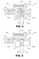
FIG. 4 . As shown inFIG. 4 , faceseal assembly 210 incorporates opposing hydrostatic face seals 212 and 214 that are formed by portions of astationary stator assembly 216 and a portion of arotating rotor assembly 218. Specifically,rotor assembly 218 provides aseal runner 220. -
Stator assembly 216 includes anarm 222 that facilitates attachment, removal and/or placement of the face seals. Acarrier 224 of the stator assembly includes a carrier member 226 (which carries face seal 212) and a carrier member 228 (which carries face seal 214). -
Hydrostatic face seal 214 includes aseal face 234, aseal dam 239, and anair bearing 243 that is fed viaair passage 241 with air from the high-pressure side (PHIGH) of theseal assembly 210. Air bearing air and leakage air passingair dam 239 will be discharged into aplenum 280 formed betweenhydrostatic face seal 214, hydrostatic face seal 212,rotor assembly 218, andcarrier 224. Air pressure inplenum 280 will be at an intermediate pressure (PINT) that is smaller than the high pressure side (PHIGH) but larger than the low pressure side (PLOW) ofassembly 210. Hydrostatic face seal 212 includes aseal face 232, which incorporates aseal dam 233, andair bearing 237 that is fed viaair passage 235 with air from the intermediate-pressure plenum 280. Air bearing air and leakage air passingair dam 233 will be discharged to the low pressure side (PLOW) ofassembly 210. - In operation, interaction between
seal face 232 andseal runner face 242 results in hydrostatic forces urgingseal face 232 away fromseal runner face 242. Simultaneously, however, interaction betweenseal face 234 andseal runner face 244 results in other hydrostatic forces urgingseal face 234 away fromseal runner face 244. These competing hydrostatic forces can be balances by compensating the decrease in air bearing supply pressure from PHIGH athydrostatic face seal 214 to PINT at hydrostatic face seal 212 with a corresponding increase in air bearing size fromair bearing 243 toair bearing 237. Hydrostatic forces, when balanced, tend to cause centering of the seal runner between the opposing seal faces 242, 244, thereby establishing the desired sealing between the low-pressure side (PLOW) and the high-pressure side (PHIGH) of theseal assembly 210. - Carrier member 226 is axially translatable so that
seal face 232 can move, with carrier member 226, away from or towardface 242 ofseal runner 220. Similarly,carrier member 228 is axially translatable so thatseal face 234 can move, withcarrier member 228, away from or towardface 244 ofseal runner 220. - An anti-rotation feature 246 is provided to prevent circumferential displacement of carrier member 226 with respect to the
arm 222 and to assist in aligning the carrier member 226 to facilitate axial translation. Ananti-rotation feature 248 is provided to prevent circumferential displacement ofcarrier member 228 with respect to carrier member 226. - A biasing
member 250, biases thecarrier members 226, 228 together to establish a defined clearance between the seal faces 232, 234. Additionally, a piston ring 252 is captured between opposingsurfaces 254, 256 of thearm 222 and carrier member 226, respectively, to control gas leakage between the arm and the carrier. - Another exemplary embodiment of a self-balancing face seal assembly is depicted schematically in
FIG. 5 . As shown inFIG. 5 , faceseal assembly 310 incorporates opposing hydrodynamic face seals 312 and 314 that are formed by portions of astationary stator assembly 316 and a portion of arotating rotor assembly 318. Specifically,rotor assembly 318 provides aseal runner 320. -
Stator assembly 316 includes anarm 322 that facilitates attachment, removal and/or placement of the face seals. Acarrier 324 of the stator assembly includes a carrier member 326 (which carries face seal 312) and a carrier member 328 (which carries face seal 314). -
Hydrodynamic face seal 312 includes aseal face 332, andhydrodynamic face seal 314 includes aseal face 334. Carrier member 226 is axially translatable so thatseal face 332 can move, with carrier member 326, away from or towardface 342 ofseal runner 320. Similarly,carrier member 328 is axially translatable so thatseal face 334 can move, withcarrier member 328, away from or towardface 344 ofseal runner 320. Notably, one or both ofseal face 332 andseal runner face 342 can include surface features for generating hydrodynamic forces when the seal runner rotates relative to the seal face. Additionally, one or both ofseal face 334 andseal runner face 344 can include surface features for generating hydrodynamic forces. - An anti-rotation feature 346 is provided to prevent circumferential displacement of carrier member 326 with respect to the
arm 322 and to assist in aligning the carrier member 326 to facilitate axial translation. Ananti-rotation feature 348 is provided to prevent circumferential displacement ofcarrier member 328 with respect to carrier member 326. - A biasing
member 350, biases thecarrier members 326, 328 to establish a defined clearance between the seal faces 332, 334. Additionally, a secondary seal 352 is positioned between opposingsurfaces 354, 356 of thearm 322 and carrier member 326, respectively, to control gas leakage between the arm and the carrier. - In operation, interaction between
seal face 332 andseal runner face 342 results in hydrodynamic forces urgingseal face 332 away fromseal runner face 342. Simultaneously, however, interaction betweenseal face 334 andseal runner face 344 results in other hydrodynamic forces urgingseal face 334 away fromseal runner face 344. These competing forces, when balanced, tend to cause centering of the seal runner between the opposing seal faces 342, 344, thereby establishing the desired sealing between the low-pressure side (PLOW) and the high-pressure side (PHIGH) of theseal assembly 310. - Notably, It should be emphasized that the above-described embodiments are merely possible examples of implementations set forth for a clear understanding of the principles of this disclosure. Many variations and modifications may be made to the above-described embodiments without departing substantially from the principles of the disclosure.
Claims (15)
- A self-balancing face seal assembly (10) comprising:a rotatable seal runner (20) having a first seal runner face (42) and an opposing second seal runner face (44);a first face seal (12) operative to form a first seal with the first seal runner face, the first face seal being one of a hydrostatic seal and a hydrodynamic seal; anda second face seal (14) operative to form a second seal with the second seal runner face, the second face seal being one of a hydrostatic seal and a hydrodynamic seal.
- The assembly of claim 1, wherein:the first face seal (12) has a first seal face (32);the second face seal (14) has a second seal face (34); andthe first seal face and the second seal face are spaced from each other at a defined clearance distance such that the seal runner (20) is positioned between the first seal face and the second seal face.
- The assembly of claim 1 or 2, wherein:the first face seal (12) is annular; andthe second face seal (14) is annular.
- The assembly of claim 1, 2 or 3 wherein, in operation, pneumatic forces urging the first face seal (12) away from the first seal runner face (42) tend to urge the second face seal (14) toward the second seal runner face (44) and pneumatic forces urging the second face seal (14) away from the second seal runner face (44) tend to urge the first face seal (12) toward the first seal runner face (42).
- The assembly of claim 1, 2, 3 or 4 further comprising a carrier (24) operative to movably position the first face seal and the second face seal relative to the seal runner.
- The assembly of claim 5, further comprising a biasing member (50) operative to bias a position of the carrier.
- The assembly of claim 5 or 6, further comprising:an arm (22), the carrier (24) being attached to and movable relative to the arm; anda secondary seal (52) operative to reduce gas leakage between the arm and the carrier.
- The assembly of any preceding claim, wherein the first face seal is a hydrostatic seal and the second face seal is a hydrostatic seal; or wherein the first face seal is a hydrodynamic seal and the second face seal is a hydrodynamic seal.
- The assembly of any preceding claim, wherein at least one of the first seal face and the second seal face is formed of a material comprising carbon.
- The assembly of any preceding claim, wherein:the assembly further comprises a stator assembly and a rotor assembly;each of the stator assembly and the rotor assembly being removable and having a corresponding mounting bracket;the stator assembly incorporating the first face seal and the second face seal;the rotor assembly incorporating the seal runner.
- A turbine assembly for a gas turbine engine comprising:a turbine (110,120) having a rotatable blades (132) and a self-balancing face seal assembly (10) as claimed in any preceding claim.
- The assembly of claim 11, wherein the seal runner (20) is operative to rotate with the blades (132).
- The assembly of claim 11 or 12, wherein the turbine is a low-pressure turbine (120).
- A gas turbine engine (100) comprising:a compressor (112,122);a shaft (114) interconnected with the compressor; anda turbine (110,120) operative to drive the shaft, the turbine having a self-balancing face seal assembly (10) as claimed in any of claims 1 to 10.
- The engine of claim 14, wherein the gas turbine engine is a turbofan.
Priority Applications (1)
| Application Number | Priority Date | Filing Date | Title |
|---|---|---|---|
| EP20090250656 EP2233700B1 (en) | 2009-03-09 | 2009-03-09 | Self balancing face seals and gas turbine engine systems involving such seals |
Applications Claiming Priority (1)
| Application Number | Priority Date | Filing Date | Title |
|---|---|---|---|
| EP20090250656 EP2233700B1 (en) | 2009-03-09 | 2009-03-09 | Self balancing face seals and gas turbine engine systems involving such seals |
Publications (2)
| Publication Number | Publication Date |
|---|---|
| EP2233700A1 true EP2233700A1 (en) | 2010-09-29 |
| EP2233700B1 EP2233700B1 (en) | 2012-05-02 |
Family
ID=40791240
Family Applications (1)
| Application Number | Title | Priority Date | Filing Date |
|---|---|---|---|
| EP20090250656 Expired - Fee Related EP2233700B1 (en) | 2009-03-09 | 2009-03-09 | Self balancing face seals and gas turbine engine systems involving such seals |
Country Status (1)
| Country | Link |
|---|---|
| EP (1) | EP2233700B1 (en) |
Cited By (4)
| Publication number | Priority date | Publication date | Assignee | Title |
|---|---|---|---|---|
| WO2014046931A1 (en) * | 2012-09-21 | 2014-03-27 | United Technologies Corporation | Turbomachine hybrid lift-off face seal |
| US9109459B2 (en) | 2013-11-11 | 2015-08-18 | General Electric Company | Apparatus and systems for sealing a rotary machine using a self-cleaning face seal |
| US9790863B2 (en) | 2013-04-05 | 2017-10-17 | Honeywell International Inc. | Fluid transfer seal assemblies, fluid transfer systems, and methods for transferring process fluid between stationary and rotating components using the same |
| WO2018005846A1 (en) * | 2016-06-30 | 2018-01-04 | General Electric Company | Turbomachine and corresponding method of assembling a face seal assembly |
Families Citing this family (1)
| Publication number | Priority date | Publication date | Assignee | Title |
|---|---|---|---|---|
| US10041367B2 (en) | 2013-12-12 | 2018-08-07 | General Electric Company | Axially faced seal system |
Citations (3)
| Publication number | Priority date | Publication date | Assignee | Title |
|---|---|---|---|---|
| US3743303A (en) * | 1970-12-29 | 1973-07-03 | Gen Electric | Force balanced split ring dynamic shaft seals |
| EP0340883A1 (en) | 1988-05-06 | 1989-11-08 | General Electric Company | High pressure seal |
| US5284347A (en) * | 1991-03-25 | 1994-02-08 | General Electric Company | Gas bearing sealing means |
-
2009
- 2009-03-09 EP EP20090250656 patent/EP2233700B1/en not_active Expired - Fee Related
Patent Citations (3)
| Publication number | Priority date | Publication date | Assignee | Title |
|---|---|---|---|---|
| US3743303A (en) * | 1970-12-29 | 1973-07-03 | Gen Electric | Force balanced split ring dynamic shaft seals |
| EP0340883A1 (en) | 1988-05-06 | 1989-11-08 | General Electric Company | High pressure seal |
| US5284347A (en) * | 1991-03-25 | 1994-02-08 | General Electric Company | Gas bearing sealing means |
Cited By (5)
| Publication number | Priority date | Publication date | Assignee | Title |
|---|---|---|---|---|
| WO2014046931A1 (en) * | 2012-09-21 | 2014-03-27 | United Technologies Corporation | Turbomachine hybrid lift-off face seal |
| US9790863B2 (en) | 2013-04-05 | 2017-10-17 | Honeywell International Inc. | Fluid transfer seal assemblies, fluid transfer systems, and methods for transferring process fluid between stationary and rotating components using the same |
| US9109459B2 (en) | 2013-11-11 | 2015-08-18 | General Electric Company | Apparatus and systems for sealing a rotary machine using a self-cleaning face seal |
| WO2018005846A1 (en) * | 2016-06-30 | 2018-01-04 | General Electric Company | Turbomachine and corresponding method of assembling a face seal assembly |
| US10626743B2 (en) | 2016-06-30 | 2020-04-21 | General Electric Company | Segmented face seal assembly and an associated method thereof |
Also Published As
| Publication number | Publication date |
|---|---|
| EP2233700B1 (en) | 2012-05-02 |
Similar Documents
| Publication | Publication Date | Title |
|---|---|---|
| US8167545B2 (en) | Self-balancing face seals and gas turbine engine systems involving such seals | |
| EP2025875B1 (en) | Hydrostatic seal and back-up seal of a gas turbine engine | |
| US8105021B2 (en) | Gas turbine engine systems involving hydrostatic face seals with integrated back-up seals | |
| US7797941B2 (en) | Gas turbine engine systems involving hydrostatic face seals | |
| US8152450B1 (en) | Floating air seal for a turbine | |
| US8540479B2 (en) | Active retractable seal for turbo machinery and related method | |
| US7909335B2 (en) | Retractable compliant plate seals | |
| US8109716B2 (en) | Gas turbine engine systems involving hydrostatic face seals with anti-fouling provisioning | |
| US20090051120A1 (en) | Gas Turbine Engine Systems Involving Hydrostatic Face Seals | |
| EP2420649A2 (en) | Intershaft seal | |
| JP2007120501A (en) | Interstage seal, turbine blade, and interface seal between cooled rotor and stator of gas turbine engine | |
| EP2233700B1 (en) | Self balancing face seals and gas turbine engine systems involving such seals | |
| US6619908B2 (en) | Axial and radial seal arrangement | |
| EP3002487B1 (en) | Sealing system | |
| GB2432638A (en) | A fluid bearing arrangement | |
| JP2016084861A (en) | Labyrinth seal device and axial flow type turbomachine | |
| US9829007B2 (en) | Turbine sealing system | |
| CA2638390A1 (en) | Seal assembly | |
| EP2025876B1 (en) | Hydrostatic seal and back-up seal of a gas turbine engine and corresponding turbine assembly | |
| EP2025877A2 (en) | Hydrostatic seal of a gas turbine engine and corresponding turbine assembly | |
| US20220106893A1 (en) | Shaft Seal System, Turbomachine with Shaft Seal System, and Method of Sealing a Shaft | |
| Justak | Hydrogen Compressor Seal Case Study-Utilizing HALO (Non-Contacting, Compliant) Inter-Stage, Impeller Eye, Buffer and Fail-Safe Seals | |
| GB2574195A (en) | Vane and shroud arrangements for a turbo-machine | |
| CN115434814A (en) | Turbine engine with rotor seal assembly |
Legal Events
| Date | Code | Title | Description |
|---|---|---|---|
| PUAI | Public reference made under article 153(3) epc to a published international application that has entered the european phase |
Free format text: ORIGINAL CODE: 0009012 |
|
| AK | Designated contracting states |
Kind code of ref document: A1 Designated state(s): AT BE BG CH CY CZ DE DK EE ES FI FR GB GR HR HU IE IS IT LI LT LU LV MC MK MT NL NO PL PT RO SE SI SK TR |
|
| AX | Request for extension of the european patent |
Extension state: AL BA RS |
|
| 17P | Request for examination filed |
Effective date: 20110318 |
|
| 17Q | First examination report despatched |
Effective date: 20110420 |
|
| AKX | Designation fees paid |
Designated state(s): DE GB |
|
| GRAP | Despatch of communication of intention to grant a patent |
Free format text: ORIGINAL CODE: EPIDOSNIGR1 |
|
| GRAS | Grant fee paid |
Free format text: ORIGINAL CODE: EPIDOSNIGR3 |
|
| GRAA | (expected) grant |
Free format text: ORIGINAL CODE: 0009210 |
|
| AK | Designated contracting states |
Kind code of ref document: B1 Designated state(s): DE GB |
|
| REG | Reference to a national code |
Ref country code: GB Ref legal event code: FG4D |
|
| REG | Reference to a national code |
Ref country code: DE Ref legal event code: R096 Ref document number: 602009006736 Country of ref document: DE Effective date: 20120621 |
|
| PLBE | No opposition filed within time limit |
Free format text: ORIGINAL CODE: 0009261 |
|
| STAA | Information on the status of an ep patent application or granted ep patent |
Free format text: STATUS: NO OPPOSITION FILED WITHIN TIME LIMIT |
|
| 26N | No opposition filed |
Effective date: 20130205 |
|
| PGFP | Annual fee paid to national office [announced via postgrant information from national office to epo] |
Ref country code: DE Payment date: 20130306 Year of fee payment: 5 |
|
| REG | Reference to a national code |
Ref country code: DE Ref legal event code: R097 Ref document number: 602009006736 Country of ref document: DE Effective date: 20130205 |
|
| REG | Reference to a national code |
Ref country code: DE Ref legal event code: R119 Ref document number: 602009006736 Country of ref document: DE |
|
| REG | Reference to a national code |
Ref country code: DE Ref legal event code: R119 Ref document number: 602009006736 Country of ref document: DE Effective date: 20141001 |
|
| PG25 | Lapsed in a contracting state [announced via postgrant information from national office to epo] |
Ref country code: DE Free format text: LAPSE BECAUSE OF NON-PAYMENT OF DUE FEES Effective date: 20141001 |
|
| PGFP | Annual fee paid to national office [announced via postgrant information from national office to epo] |
Ref country code: GB Payment date: 20220225 Year of fee payment: 14 |
|
| GBPC | Gb: european patent ceased through non-payment of renewal fee |
Effective date: 20230309 |
|
| PG25 | Lapsed in a contracting state [announced via postgrant information from national office to epo] |
Ref country code: GB Free format text: LAPSE BECAUSE OF NON-PAYMENT OF DUE FEES Effective date: 20230309 |
|
| PG25 | Lapsed in a contracting state [announced via postgrant information from national office to epo] |
Ref country code: GB Free format text: LAPSE BECAUSE OF NON-PAYMENT OF DUE FEES Effective date: 20230309 |